

Page 1
www.powmatic.co.uk
+44 (0) 1460 53535
info@powrmatic.co.uk
Doc Ref: M401 Issue 5.4 Feb 2018
Industrial & Commercial Heating Systems
MC200/V3 Control System
User, Installation
& Servicing Manual
Page 2
page no. 2 of 24
MC200/V3 Users, Installation & Servicing Instructions Doc Ref M401 issue 5.4 Feb 2018.
Installer
Date:________________Signed: _____________________________________Installer
Important: This certicate
must be kept with the appliance
Failure to provide a copy of the commissioning sheet invalidates the heater warranty
----------------------------------------------------
Powrmatic Ltd, Hort Bridge, Ilminster, Somerset, TA19 9PS
Tel: 01460 53535 Fax: 01460 52341
Web: www.powrmatic.co.uk e-mail: warranty@powrmatic.co.uk
Certificate of Guarantee
Dear Customer
This is to certify that this controller is guaranteed for a period of one year from the date of original
installation.
To make a claim
In the rst instance you must contact your appliance supplier, or installer and provide:-
1. The appliance type and order number.
2. The original commissioning documentation. As much detail as possible on the fault.
3. Your supplier, or installer, will then contact Powrmatic to make a guarantee claim on your behalf.
Conditions of Guarantee
1. The controller must have been installed by a competent recognised installer, and in
accordance with the manufacturer’s instructions, I.E.E. regulations and local regulations.
2. The controller has been used in accordance with the manufactures instructions.
3. No unauthorised repairs of modications have been made. Powrmatic ‘General Conditions of
Sales’ have been observed.
4. Except for the obligation of Powrmatic Ltd to perform warranty repairs during the guarantee
period Powrmatic will not be liable in respect of any claim for direct or indirect consequential
losses, including loss of prots or increased cost arising from loss of use of the heater, or any
event arising there from.
Page 3

page no. 3 of 24
MC200/V3 Users, Installation & Servicing Instructions Doc Ref M401 issue 5.4 Feb 2018.
Dear Customer - thank you for choosing Powrmatic.
We appreciate you buying one of our high quality products and know that you have made the best
choice. By choosing Powrmatic, you are investing in UK manufacturing & its workforce. We pride
ourselves by manufacturing products that provide clean, comfortable and safe working environments
worldwide together with the personal & professional service and back-up you deserve. If you have
any questions or concerns regarding this product, please contact our Technical Support Team by
calling 01460 53535.
Title Section Contents Page
User Instructions 4
Pre Installation
1.1 Introduction 9
1.2 Technical data 11
Dimensions 11
Installation
2.1 Fitting the unit 12
2.2 Electrical Cable Installation 13
2.3 Interconnecting Wiring Diagrams 15
2.4 Commissioning and Output Sequences 19
Additional Documents
3.1 Fault Displays and Fault Finding 22
3.2 Short Parts List and Options 24
Users, Installation and Servicing Instructions
CONTENTS
Page 4
page no. 4 of 24
MC200/V3 Users, Installation & Servicing Instructions Doc Ref M401 issue 5.4 Feb 2018.
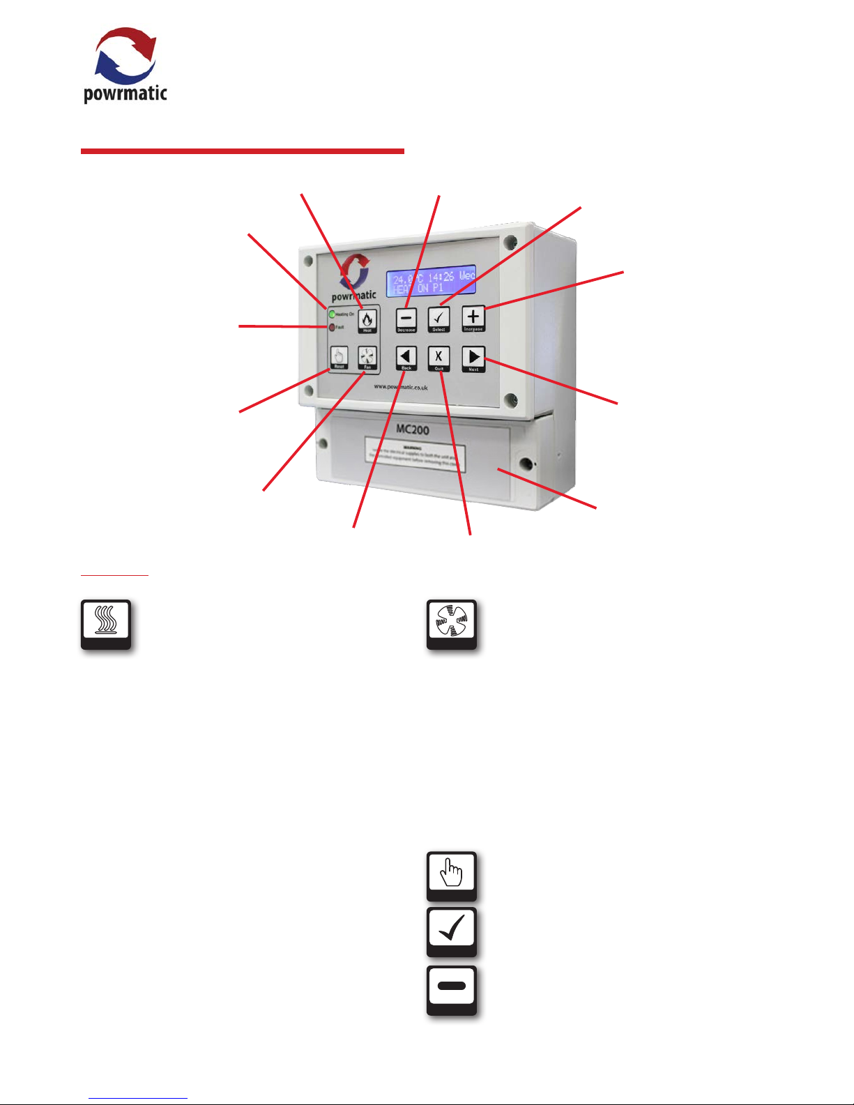
Heat Button.
Heating On Indicator
Fault Indicator
Fan Button
Burner Lockout
Reset Button
Back Button
Quit Button
Next Button
Increase Button
Select Button
Decrease Button
Heat
Heat Button - (Note: this facility may be limited
or disabled by the User).
If heating is ON (via programme)
Pressing the Heat button for less than 2 seconds overrides
the programme to OFF. Any extension time that has been
set is cancelled.
Pressing the heat button for more than 3 seconds
determines that heat will remain on for an extension time
after the programmed o time. The extension timer will
increase in 30 minute steps, up to the maximum allowed
period, and then revert to 0 minutes.
Release the button when the required extension period is
showing.
If heating is OFF (via override)
Pressing the Heat button removes override and reverts to
the current programme. If heating is OFF (via programme)
Pressing the Heat button for less than 2 seconds brings on
heating for 30 minutes.
Pressing the heat button for more than 3 seconds
will increase the on time in 30 minute steps, up to the
maximum allowed period, and then revert to 0 minutes.
Release the button when the required heating period is
showing.
Fan
Fan Button - (Note: this facility may be limited
or disabled by the User).
In WINTER mode and OFF mode, the Fan button has no
control over the air heater fan.
In SUMMER mode, the Fan button switches on the fan for
air circulation, and another press switches it o. If the fan is
left on, it will be automatically switched o at midnight.
If the fan is running because the heating is on and the fan
is in AUTO or CONST mode, the Fan button cannot switch
it o.
If the fan is in an ON mode, it always runs, in WINTER,
SUMMER and OFF. The Fan button cannot switch it o.
Reset
Reset Button - Press to reset the burner controls
from lockout, (when this facility is available on
the heater).
Select
Select Button - Press to accept changes.
Decrease
Decrease Button - Press to decrease values.
A) Buttons
Terminal Cover
User Instructions
Page 5
page no. 5 of 24
MC200/V3 Users, Installation & Servicing Instructions Doc Ref M401 issue 5.4 Feb 2018.
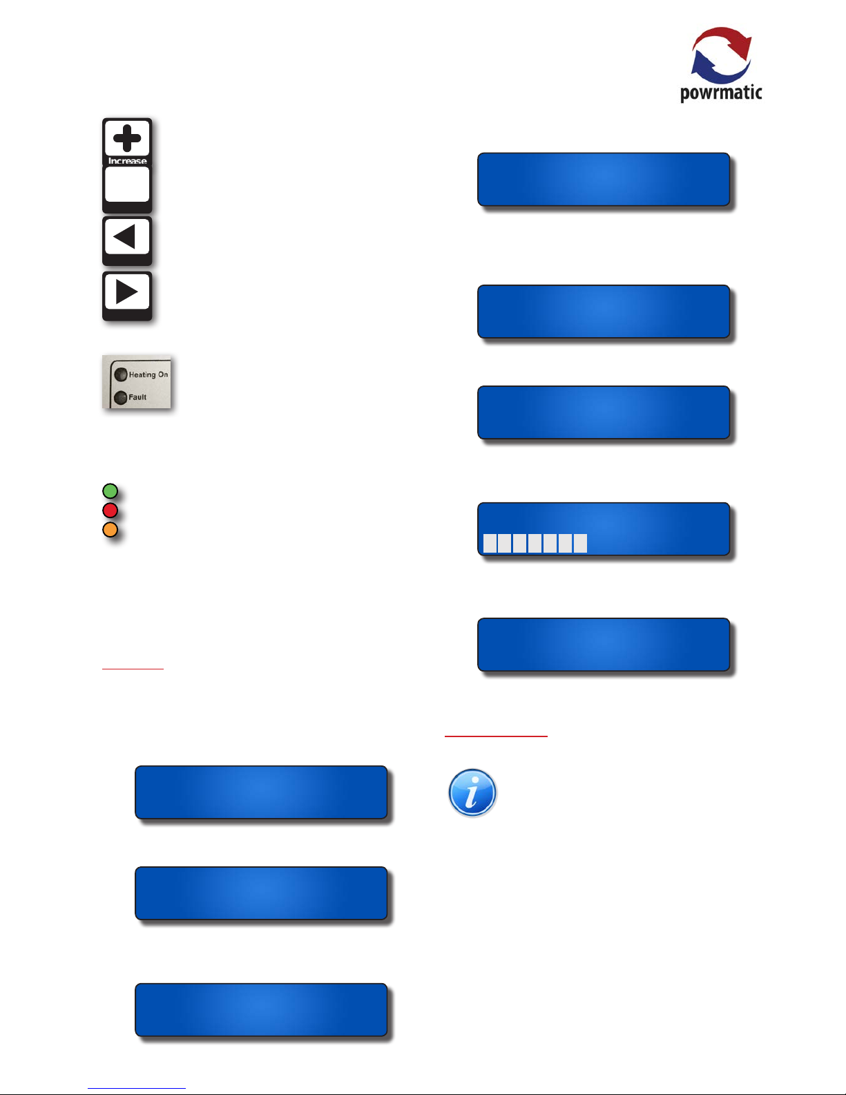
Increase
Increase Button - Press to increase values.
Quit
X
Quit Button - Press to exit without saving
changed values.
Back
Back Button - Press to enter User Menu, go
back to previous screen.
Next
Next Button - Press to enter User Menu, go
forward to next screen.
Indicators
Heating On - Is illuminated when the MC200 is calling
for heat (It does not conrm that the heating is actually
working).
Green when the heater is a single-stage burner.
Red when the heater is a Hi-Low type.
Yellow when the heater has a Modulating burner.
Fault - Flashes when the burner control is at lockout, solid
light when a service call is due (if this has been set) or when
there is a sensor fault. The bottom line of the display will
alternate between normal display and type of fault.
B) Display
The rst display normally shows:
• the current air temperature as measured by the internal
sensor, an external sensor or the average temperature if
two sensors are tted.
8.5.C 09:42 Tue
P1 HEAT ON
• the time of day using 24-hr notation. The colon ashes
once per second to conrm that the clock is running.
8.5.C 09:42 Tue
P1 HEAT ON
• the day of the week. Programmes are associated with
individual days of the week or day-groups such as weekday
or weekend.
8.5.C 09:42 Tue
P1 HEAT ON
• Programme number - Px n (where x represents the active
programme number.)
8.5.C 09:42 Tue
P1 HEAT ON
• the current setting of the heater: ON or OFF, as
determined by the internal programmes (the display will
say ON even if the MC200 is not currently calling for heat
because the thermostat is satised)
8.5.C 09:42 Tue
P1 HEAT ON
or for High/Low an indication of the heat demand. HEAT HI
or HEAT LO,
8.5.C 09:42 Tue
P1 HEAT HI
or for Modulating burners a simple bar-graph display for
modulating control heaters where 1 bar is low re and 10
bars is high re.
8.5.C 09:42 Tue
P1
• “Frost Guard” is displayed when Frost/setback is set to
ON and the space temperature is lower than the Frost/
setback temperature setting.
0.5.C 09:42 Tue
Frost guard
C) Direct Control
Note: If congured during the commissioning
stage the User has the following direct control
of the heater without using the settings menu.
• If the Fault LED is on because the heater is at lockout, the
user can reset the heater by pressing the Reset button.
• The user can switch the heating ON or OFF by pressing
the Heat button.
• The user can start or cancel extension time by pressing
the Heat button longer than 3 seconds.
• The user can run the fan without heating, by pressing the
Fan button.
• Pressing of the next button will scroll through the screen
displays available to the user
Page 6
page no. 6 of 24
MC200/V3 Users, Installation & Servicing Instructions Doc Ref M401 issue 5.4 Feb 2018.
Temperature 18.0
Date: 20/08/2017
Password ****
Next
Next
Next
8.5.C 09:42 Tue
HEAT OFF FAN OFF
Next
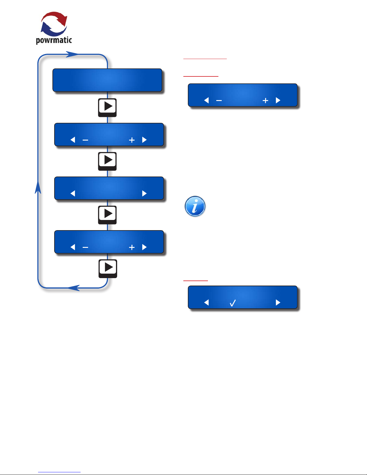
The top line will show which setting or which part of the
programmes you are viewing.
The second line of the display shows which keypad buttons
are active ( ◄ – ü X + ► ).
After changing any setting, press the ü button to save the
new setting.
To return to the normal display, press the X button or do
not touch any buttons for 15 or more seconds.
Keys ◄, ►, – and + will auto-repeat if held down longer
than approximately half a second.
The + button will automatically wrap round from the
maximum value to the minimum value and the – button
will wrap the other way
D) User Settings
Temperature
Temperature 18.0
This shows the temperature set by the currently
active programme, and it is the target temperature for
thermostatic control. The user can increase or decrease
the value to adjust comfort. This will not alter the set
temperature associated with the programme, but it will
temporarily alter the target temperature for thermostatic
control.
The eect of altering the temperature lasts until the
current programme expires or until another programme
changes the set temperature requirement.
Note: the range of adjustment permitted may
be limited during commissioning. Temperature
adjustment can be disabled by a setting within
the user menu.
• Press the + or - button to increase or decrease the day
temperature set point.
• Press the ü button to save changes, press the X button
to exit without saving, press the ► button to move to the
next setting.
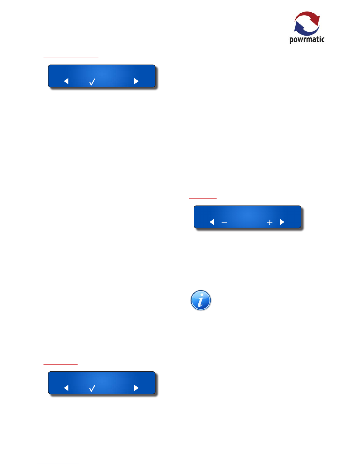
Clock Set
Clock set
Sets the current date and the time of day. The correct date
allows the MC200 to know the day of the week, allows for
automatic BST-GMT changeovers, carries out the holiday
shutdown function and permits override password entry.
• Press the ü button to alter date and/or time.
• Press the ◄ or ► button to select digit to change (digit
chosen will ash).
• Press the + or - button to change the digit.
• Press the ◄ or ► button to select next digit to change
or until 'Set clock?' appears on screen
• Press the ü button to save changes, press the X button
to exit without saving, press the ► button to move to the
next setting.
Page 7
page no. 7 of 24
MC200/V3 Users, Installation & Servicing Instructions Doc Ref M401 issue 5.4 Feb 2018.
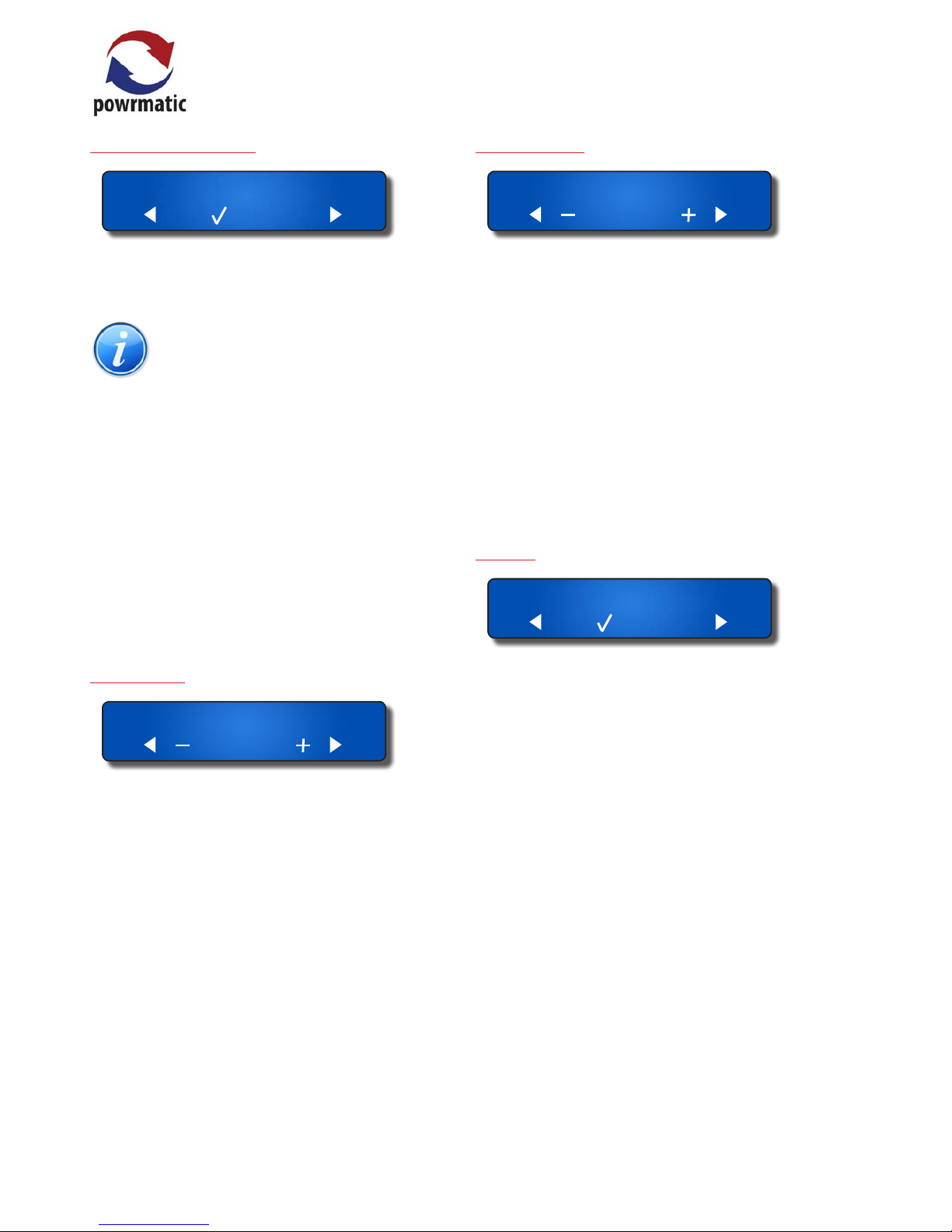
Programme settings
P rog settings
The MC200 has 14 programmes, each of which can be
assigned to any day of the week. Each programme can be
given an ON time, an OFF time and a set temperature. The
user may organize the programmes in any way that suits.
The simplest would be one programme ON in the morning,
OFF at the end of the afternoon, active Monday to Friday.
If two or more programmes are active at the same time,
for instance one is ON all day and another is ON between
11:00 and 13:00, then the set temperature of the second
programme will apply between 11:00 and 13:00, and the
set temperature of the rst programme will apply during
the rest of the working day.
Programme times increment in 5 minute steps.
Extension time (if set) applies when all programmes have
reached the end of their set period for that day.
Optimum start applies at the beginning of the rst
programme to switch on and optimum stop applies at the
end of the last programme to switch o.
• Press the ü button to set/alter programme.
• Press the ü button to alter programme P1 or the + or button to select specic programme number then press
the ü button to accept.
• Press the + or - button to alter/set the HEAT ON time.
• Press the ► button to move to the HEAT OFF time
• Press the + or - button to alter/set the HEAT OFF time.
• Press the ► button to move to the temperature
• Press the + or - button to change the temperature.
• Press the ► button to move to the Programmed days
• Press the + or - button to alter between: Mon-Fri; SatSun;
7 days; O or individual days.
• Press the ► button to and 'Save Prog x?' will appear.
• Press the ü button to save changes, press the X button
to exit without saving, press the ► button to move to the
next setting.
Holiday Date
H oliday date
A future date can be set so that the heating will not
operate on that date, and remains “OFF” for a consecutive
number of days from that date. The date includes the year
number, ensuring that the holiday shutdown date is not
automatically repeated the following year.
During the holiday period the heater will only operate
if the temperature falls below the frost temperature
and if frost temperature operation is selected “ON” in
the engineer menu. The night temperature setting is
ignored during holidays. During the holiday period,
manual operation of the fan or heater is permitted. Any
manual operation still on at midnight will be automatically
cancelled.
• Press the ü button to add a holiday period.
• Press the + or - button to set the start date.
• Press the ► button to select the month to change.
• Press the + or - button to set the month.
• Press the ► button to select the year to change.
• Press the + or - button to set the year.
• Press the ► button to select the number of days.
• Press the + or - button to enter the number of days.
• Press the ► button to and 'Holiday save?' will appear.
• Press the ü button to save changes, press the X button
to exit without saving, press the ► button to move to the
next setting.
Run Mode
Run mode: WINTER
The MC200 has three Run modes: WINTER, SUMMER and
OFF.
Winter - the heating operates when any programme is in a
“HEAT ON” period. The heating also operates to maintain
the Night Temperature if this has been set. The heating
also operates when the temperature drops below the frost
temperature.
NOTE: Summer/Winter mode has no
connection with the clock change from GMT to
BST.
Summer - the fan operates to circulate air when switched
on manually. With certain types of heater or certain types
of installation, Fan-only operation may not be appropriate
and the fan control circuit should not be used.
In SUMMER the heating never operates unless the
temperature drops below the frost temperature.
During commissioning the frost temperature operation will
be set to be ON or OFF. If the frost setting is OFF, the heater
will not operate under frost conditions in any User mode.
OFF - the heater never operates unless the temperature
drops below the frost temperature (see above)
• Press the + or - button to change between WINTER,
SUMMER & OFF.
• Press the ü button to save changes, press the X button
to exit without saving, press the ► button to move to the
next setting.
Page 8
page no. 8 of 24
MC200/V3 Users, Installation & Servicing Instructions Doc Ref M401 issue 5.4 Feb 2018.
User Button Permission
P ermissions
This menu option facilitates the user to enable or disable
the following controls separately if it is required to restrict
unauthorised access to user controls.
NOTE: User permissions are only eective when
User access to the menu is protected by a
password.
Reset - Allows operation of the reset button
Change temperature - Allows temporary adjustment of
the current set temperature
Heat Override - Allows switching ON/OFF and extension
of Heat ON time
Fan override - Allows switching ON/OFF of the fan
• Press the ü button to alter the permissions.
• Press the + or - button to toggle between YES & NO..
• Press the ► button to select next digit to change or until
'Save??' appears on screen
• Press the ü button to save changes, press the X button
to exit without saving, press the ► button to move to the
next setting.
Set Password
SetPassw ****
The user may enter a 4-digit password here. Once set, the
password must be given before selected user controls may
be accessed or changed. “Set password” cannot be entered
unless the password has been given.
As delivered, the MC200 has no User password restrictions,
the user password being set to 0000. Entering a password
of 0000 will remove all restrictions.
• Press the + or - button to set the rst digit.
• Press the ► button to select the next digit.
• Press the + or - button to set the second digit.
• Press the ► button to select the next digit.
• Press the + or - button to set the third digit.
• Press the ► button to select the next digit.
• Press the + or - button to set the last digit.
• Press the ü button to save changes - 'SET OK' will appear
briey, press the X button to exit without saving, press the
► button to move to the next setting.
Extension Time
Extend time 1:00
A user can extend the heating to operate beyond the
switch-o time of the last programme of the day, in
30minute increments, by pressing the Heat button. This
menu option allows a maximum extension period to be
set, in units of 30minutes.
If set to 0 minutes, extension is not permitted.
Factory default setting: 1hour. Maximum setting 3hours.
• Press the + or - button to set the appropriate extended
time.
• Press the ü button to save changes - 'Setting saved' will
appear briey, press the X button to exit without saving,
press the ► button to move to the next setting.
Cost Log
C ost Log
This option shows the total hours run and the total cost
of running since the log was last cleared. The display will
show the date when it was last cleared. For this option to
function it is necessary to enter the fuel cost and heater
rating (see Engineer Menu for the latter). The cost log
should be cleared whenever the heater type is changed.
For Hi/Lo heaters, there are two heater power entries and
the MC200 will calculate the run cost according to the level
of heat requested.
In the case of modulating control heaters, the cost is an
estimate based on half the full heater power.
• Press the ü button to enter the submenu. Display shows
Start Date.
• Press the ► button to select next screen 'Total Hours'.
• Press the ► button to select next screen 'Total Cost'.
• Press the ► button to select next screen 'Clear Log?'.
• Press the ü button to clear log. This will reset the start
date to the current date.
• Press the ► button to select next screen 'costs per kWh'
• Press the + or - button to change th cost per kWh.
• Press the ü button to save changes, press the X button
to exit without saving, press the ► button to move to the
next setting.
Page 9

page no. 9 of 24
MC200/V3 Users, Installation & Servicing Instructions Doc Ref M401 issue 5.4 Feb 2018.
Password
Password ****
Once a password has been set, the password must be
entered at this menu option to allow access to selected
user controls.
Once entered the password gives access to the User menu
functions for 60 minutes.
To re-apply the restrictions before the end of the 60 minute
period, select the ‘Enter password’ option and press the ü
button without entering any digits. The display will show
‘Password CLOSED’.
• Press the + or - button to set the rst digit.
• Press the ► button to select the next digit.
• Press the + or - button to set the second digit.
• Press the ► button to select the next digit.
• Press the + or - button to set the third digit.
• Press the ► button to select the next digit.
• Press the + or - button to set the lat digit.
• Press the ü button to save changes - VALID will appear
briey, press the X button to exit without saving, press the
► button to move to the next setting.
If 'FAIL' appears on the screen, the incorrect password has
been entered. Repeat entry sequence.
E) Additional notications
Service Date
When the MC200 is installed the Commissioning Engineer
may have entered a date for when the heating equipment
requires servicing.
When this date is reached the MC200 fault indicator will
be illuminated and the display will alternate between the
normal display and "Service due, call engineer".
S ervice due,call
engineer
The Service Engineer can clear this display by entering a
new service date when the heating equipment has been
serviced.
The MC200/V3 is a high specication heating controller
designed specically to meet the demands of modern fuel
ecient heating equipment and the latest energy saving
and environmental guidelines and uses a simple menu
based structure for entering User settings.
Optimum start technology is available that will continually
monitor the heating systems previous performance to
determine the optimum time to turn the heating on to
raise the space temperature to the required level for when
occupancy begins. Optimum stop can also be selected
which can save energy at the end of the heating period.
The MC200/V3 is protected by 2 levels of password. The
User password may be set to restrict access to certain User
controls. The second password is for use by commissioning
and servicing engineers and allows access to parameters
normally used only in the initial setting of the controller, a
fault log and system reset facility.
The user keypad allows easy selection of the heating and
fan only modes, the override functions and fault reset.
These may also be locked in various combinations to allow
dierent levels of user accessibility.
The MC200/V3 can give a readout of the hours the burner
has operated, to help accessing servicing intervals and
after being programmed with the correct data, can also
give an indication of the running costs of the heating
appliance. In addition a forward service date can be
programmed. When the due date is reached a notication
will be shown which alternates with the normal display.
This notication can only be removed by a Service
Engineer.
The MC200/V3 can be used to directly control both Hi/
Lo and Modulating burners, the latter by an internally
generated 0-10V signal.
1.1.2 Clock
• The unit date range is from 01/01/2001 to 31/12/2099
• Leap years are recognised
• BST begins on the last Sunday in March and ends on the
last Sunday in October. The time changes at 01:00 GMT.
• The clock may gain or lose up to 10 minutes in a year.
1.1.3 Programme
• 14 timers are provided in the software, and each can be
assigned to any single day of the week, or to day groupings
such as weekdays or weekends. This allows greatest
exibility in operating the heating whenever required.
• It is possible to schedule timers so that one starts
before another has nished. The heating will be on while
1.1 Introduction
Page 10

page no. 10 of 24
MC200/V3 Users, Installation & Servicing Instructions Doc Ref M401 issue 5.4 Feb 2018.
Important: Optional sensors are available
from Powrmatic Ltd. Alternative types must
not be used.
It can also be used in conjunction with an additional
remote sensor which will give an average of the two
temperature readings.
Options are:
• Default internal sensor only
• Remote sensor only
• Internal sensor plus remote sensor
• Remote sensor plus remote sensor
The remote sensor should be sited no further than 100m
from the main unit. Siting of the sensor is important in that
it must be tted where the temperature will be generally
representative of the area to be heated.
It should be installed 1.7m above oor level and away
from draughty areas or areas subjected to direct heat from
sunlight, radiators etc.
The second 'sensor' input can also accept a volt free switch
input i.e. a volt free switch is connected across Terminals
Com & In2 to facilitate a remote on (BMS) or remote o.
Heating will be overridden by the switch operation during
programmed heating times. Heating control returns to
normal when the switch reverts, or when the programmed
control period ends.
The switched control does not occur while heating is
turned on due to manual override in non-programmed
times, and does not occur during the manually-selected
extension time at the end of a programmed control period.
If heating has been manually overridden to be o during a
programmed heating period, the switched control cannot
bring on the heating.
The ‘Heat on’ option means that heat will be turned fully
on by the switch. For high-low burners, the high and low
relays will be on, and for modulating burners, the control
output will be 10v.
Cost logging operates as usual. During these switch control
periods the burn time is recorded at the maximum rate.
If the sensor goes open-circuit (if either of the sensors goes
open-circuit where two are tted), the Fault LED will ash.
The LCD display will show “sensor failed”.
Important: The earlier MC100 sensor cannot
be used with the MC200/V3 and the MC200/
V3 sensor cannot be used with the MC100.
any timer is requiring Heat On, and the heating will turn
o only when all timers have reached Heat O. The
requested temperature will be set by the most recent timer
to switch On. When an overlapping timer switches O,
the requested temperature will be set by the remaining
timer(s).
• No timer can be programmed to run past midnight,
because it is assigned to a day of the week. If timed
heating is required across midnight, it must be provided
by two timers, one ending at 23:59 and the other starting
at 00:00. At midnight, all manual over-rides and extensions
are cleared.
1.1.4 Optimum Start
A control system which starts plant operation at the latest
possible time such that internal conditions will be up to
required limits at the start of the occupancy period.
• The MC200/V3 achieves Optimum start by keeping
a moving record of how many minutes it takes to
increase the temperature per degree in each 3° band
of temperature from 5°C to 20°C. The current overnight
temperature is referenced and the MC200/V3 can estimate
how many minutes are required to bring the temperature
to the required level.
When Optimum Start is enabled the switch-on time for
the heater is then advanced accordingly to achieve the
required temperature by the Heat On time i.e. the warmer
the night time temperature the closer the switch on time
will be to the Heat On time.
NOTE: If optimum start is selected, no program
time should be selected to start before 2:00am.
1.1.5 Optimim Stop
A control system which stops plant operation at the earliest
possible time such that internal conditions will not deteriorate
beyond preset limits by the end of the occupancy period.
• The MC200/V3 keeps a note of how many minutes are
taken for the temperature to drop the number of degrees
entered against this parameter when the heating period
ends. When Optimum Stop is enabled, the MC200/V3
switches o the heating that number of minutes early.
1.1.6 Temperature Sensors
The MC200 has an in-built temperature sensor by default.
This can me removed and replaced with a remote sensor if
the controller is outside the area to be heated.
The remote sensor may be either a room (warm air), black
bulb (for radiant) or duct type.
Page 11

page no. 11 of 24
MC200/V3 Users, Installation & Servicing Instructions Doc Ref M401 issue 5.4 Feb 2018.
Dimensions
165mm
160mm
85mm
Electricity supply 230V 50Hz Fused at 6A.
Internal Fuses F1 20mm 6.3A 230V.(HRC), F2 20mm 500mA 230V. (Non replaceable)
Display 2 line 5mm Backlit L.C.D.
Day set point range 10 - 60°C.
Night set point range 1 - 15°C.
Temperature accuracy 0.5 °C.
Overall switching dierential Adjustable 0.5 - 10.0°C for Hi/Lo burner types.
Sensing Element Internal or remotely mounted up to 100m from control.
Switching contacts ratings 12A. 230V.ac. (resistive). All Volt Free
Modulating Control 0-10V dc
Heating ON Indicator
Green L.E.D. when the heater is a single-stage burner,
Red when the burner is a Hi-Low type,
Yellow when the burner is a Modulating type.
Fault (Lockout) Indicator Orange L.E.D.
Protection Rating IP20
Software versions G
1.2 Technical Data
Page 12

page no. 12 of 24
MC200/V3 Users, Installation & Servicing Instructions Doc Ref M401 issue 5.4 Feb 2018.
2.1.1 Fitting space requirement
The controller will be delivered to site in a cardboard box.
The box may have a xing template on the rear to aid
drilling the xing holes. If not, the base of the controller
housing has the xing dimensions imprinted into the
plastic.
All of the packaging can be recycled. Please
make use of local recycling facilities.
Important: The MC200/V3 and sensor
MUST NOT be sited in areas of high
electromagnetic elds, i.e. distribution
boards, transformers or heavy duty supply
cables.
2.1.1 Location
Siting of the MC200/V3 is important in that it must be
tted where the temperature will be representative of the
area being heated.
It should be installed 1.7m above oor level (unless a
remote sensor is being used) and away from draughty
areas or areas subjected to direct heat from sunlight,
radiators etc. It must also be easily accessible for
programming and operation.
2.1.2 Fixing
The MC200/V3 will accept cable entry from the bottom
and the back.
112mm
151mm
15mm
Remove the two screws from the terminal cover and
remove.
Check that the unit ts in the intended mounting position.
Using the template on the packaging box (invert if
necessary) or using the dimensions on the back of the
housing, mark the location of the three xing holes.
Fit the top (or bottom if inverted) screw leaving
approximately 5mm protruding. Locate the MC200 on the
top (or bottom if inverted) xing screw, line up the bottom
(or top if inverted) xing holes and secure using two
screws.
The warning label supplied loose must be applied centrally
to the terminal cover.
If required the unit may be inverted by the following
procedure so that cable entry is from the top.
NOTE: that in this orientation the internal
sensor cannot be used and a remote sensor
must be used instead albeit it can be alongside
the MC200/V3.
Remove the four screws that secure the top (keypad and
display) section.
Rotate the section through 180°, the ribbon cable is long
enough to allow this, and ret the top section to the case.
Alternatively a sub base is available, as an optional extra, to
allow cable entry from the top or side.
2.1.2 Remote Sensor Fixing (optional)
The remote sensor should be installed 1.7m above oor
level and away from draughty areas or areas subjected to
direct heat from sunlight, radiators etc. and should be sited
no further than 100m from the main unit
Additionally, Radiant Black Bulb sensors should also be in
sight of at least one of the radiant tubes.
Duct sensors should be placed in a position to receive a
representation of the duct temperature.
Remove cover and oer the sensor up to the intended
mounting position and mark two xing holes.
Fix sensor base plate to the wall, complete wiring
connections (2 core screened cable) and ret cover.
2.1 Fitting the Unit
Page 13

page no. 13 of 24
MC200/V3 Users, Installation & Servicing Instructions Doc Ref M401 issue 5.4 Feb 2018.
2.2.1 Electrical Connections
Warning: Wiring external to the MC200 must
be installed in accordance with I.E.E.
Regulations together with any local
regulations which may apply.
Wiring terminals are located beneath the electrical lower
front cover. Wiring should be completed in conduit, for
which knockouts are provided in the bottom of the casing.
Mains supply and control circuit wiring should be
completed in cables not less than 0.5mm² and fan circuit in
not less than 1.5mm².
The connection to the mains electrical supply can be taken
from the appliance or a separate ‘local’ supply, but in both
cases a local isolator must be tted adjacent to the MC200.
Should more than one appliance be controlled from one
MC200 an interfacing relay box MUST BE USED with the
MC200 driving the relay coils.
Warning: Sensor cable must be screened two
core and a minimum of 0.6mm² if solid and 7 x
0.2mm² if multistrand. The screen must be
grounded only at the MC200.
Wiring for the temperature sensor MUST BE RUN
SEPARATELY and apart from ALL other wiring. Failure
to regard this instruction may cause the MC200 to
malfunction and may render it faulty.
Under no circumstances must voltage be applied to the
sensor connections.
Warning: Burner Reset terminal is
internally connected to NEUTRAL when the
reset button is pressed.
2.2 Electrical Cable Installation
Terminal Type Function Terminals
SEN1 Input Connection for prime external sensor (not polarity sensitive)
COM Input Common connection for sensors and/or auxiliary switch
IN2 Input Connection for 2nd sensor (averaging) and or auxiliary switch
0-10V + Output 0-10Vdc output for modulation control MODULATION BURNERS ONLY
0-10V - Output 0Vdc (ground) output for modulation control MODUL ATION BURNERS ONLY
RESET Output NEUTRAL reset output (internally connected)
LOCKOUT Input Receives mains voltage lockout signal from burner
Heat Hi IN Input Hi Heat input (common relay contact)
Heat Hi OUT Output Hi Heat output (normally open relay contact)
Heat Lo IN Input Low heat/Heat input (common relay contact)
Heat Lo OUT Output Low heat/Heat output (normally open relay contact)
Fan IN Input Fan input (common relay contact)
Fan OUT Output Fan output (normally open relay contact)
L OUT Output 6.3A fused 230V output terminal for heat/fan circuits where required
N Input NEUTRAL
E Earth EARTH
L Input LIVE
Notes:
No Voltage - Voltage must not be applied to the sensor terminals. If a switch is tted accross COM and IN2, it must be volt free.
230V 50Hz Mains Voltage
Volt Free pair - If a voltage is required (230V, 24V, 110V etc) the appropriate voltage must be applied to the corresponding input
terminal.
MC200V3
SEN 1
COM
IN 2
0-10v +
0-10v -
Reset
Lockout
Heat Hi
In
Heat Hi
Out
Heat Lo
In
Heat Lo
Out
Fan In
Fan Out
L Out
N
E
L
6.3A
HRC
Page 14

page no. 14 of 24
MC200/V3 Users, Installation & Servicing Instructions Doc Ref M401 issue 5.4 Feb 2018.
2.2.2 External Wiring
Notes:
Wiring for High/Low burners only
Wiring for modulation burners only
2.2.2.1 Wiring details for current Powrmatic heaters utilising fused live output terminal 14 and detailing 'link' wires.
Fan Only
circuit
Low Heat
circuit
Lockout
Reset
0-10Vdc
0Vdc
IN2/Sen 2
COM⁄
Sen 2
NEUTRAL
EARTH
LIVE
High Heat
circuit
Fan Only
Low Heat
Lockout
Reset
0-10Vdc
0Vdc
IN2/Sen 2
COM⁄
Sen 2
NEUTRAL
EARTH
LIVE
High Heat
2.2.2.2 Wiring details for older Powrmatic heaters utilising volt free heat and fan terminals
Wiring for external remote sensor only
Wiring for remore switch only
Wiring for Burner Lockout heaters only
Page 15

page no. 15 of 24
MC200/V3 Users, Installation & Servicing Instructions Doc Ref M401 issue 5.4 Feb 2018.
2.3 Interconnecting Wiring Diagrams to typical heaters
MC200 Controlling
High/Low ErP NVx or VPC
MC200 Controlling
Modulating ErP NVx or VPC
MC200 Controlling
High/Low ErP OUH
SEN 1
COM
IN 2
0-10v +
0-10v -
Reset
Lockout
Heat HiInHeat Hi
Heat Lo
Out
In
Heat Lo
Fan In
Out
Fan Out
N
L Out
E
L
E654321
MC200 Fuelsaver
NVx or VPc ErP High/Low
6.3A
HRC
1110987
L
N E
L
N E
SEN 1
COM
IN 2
0-10v +
0-10v -
Reset
Lockout
Heat HiInHeat Hi
Heat Lo
Out
In
Heat Lo
Fan In
Out
Fan Out
N
L Out
E
L
E654321
MC200 Fuelsaver
NVx or VPc ErP Modulating
6.3A
HRC
1110987
L
N E
L
N E
v - v +
SEN 1
COM
IN 2
0-10v +
0-10v -
Reset
Lockout
Heat HiInHeat Hi
Heat Lo
Out
In
Heat Lo
Fan In
Out
Fan Out
N
L Out
E
L
E654321
MC200 Fuelsaver
OUH ErP High/Low
6.3A
HRC
1110987
L
N E
L
N E
2.3.1 2018 ErP Products
Page 16

page no. 16 of 24
MC200/V3 Users, Installation & Servicing Instructions Doc Ref M401 issue 5.4 Feb 2018.
SEN 1
COM
IN 2
0-10v +
0-10v -
Reset *
Lockout
Heat HiInHeat Hi
Heat Lo
Out
In
Heat Lo
Fan In
Out
Fan Out
N
L Out
E
L
11109876
MC200 Fuelsaver
CPX ErP High/Low
6.3A
HRC
15141312
L
N E
L
N
E
* not used on Oil fired units
MC200 Controlling
High/Low ErP CPx
2.3.2 Non- ErP Products
SEN 1
COM
IN 2
0-10v +
0-10v -
Reset
Lockout
Heat HiInHeat Hi
Out
Heat Lo
In
Heat Lo
Out
Fan In
Fan Out
L Out
N
E
L
MC200 CONTROLLING
ON/OFF NVx or VPc
EN
L
654321
MC200 Fuelsaver
ON/OFF
NVx or VPc
N
L
E
6.3A
HRC
MC200 CONTROLLING
Hi/Lo NVx / VPc
SEN 1
COM
IN 2
0-10v +
0-10v -
Reset
Lockout
Heat HiInHeat Hi
Out
Heat Lo
In
Heat Lo
Out
Fan In
Fan Out
L Out
N
E
L
EN
L
654321
MC200 Fuelsaver
Hi/Lo
NVx or VPc
N
L
E
6.3A
HRC
MC200 Controlling
ON/OFF NVx or VPC
MC200 Controlling
HI/LOW NVx or VPC
Page 17

page no. 17 of 24
MC200/V3 Users, Installation & Servicing Instructions Doc Ref M401 issue 5.4 Feb 2018.
MC200 Controlling
ON/OFF CPx
MC200 Controlling
HI/LOW CPx
SEN 1
COM
IN 2
0-10v +
0-10v -
Reset
Lockout
Heat HiInHeat Hi
Out
Heat Lo
In
Heat Lo
Out
Fan In
Fan Out
L Out
N
E
L
EN
L
10
9876
MC200 Fuelsaver
ON/OFF
CPx
N
L
E
6.3A
HRC
SEN 1
COM
IN 2
0-10v +
0-10v -
Reset
Lockout
Heat HiInHeat Hi
Out
Heat Lo
In
Heat Lo
Out
Fan In
Fan Out
L Out
N
E
L
EN
L
1413
876
MC200 Fuelsaver
Hi/Lo
CPx
N
L
E
6.3A
HRC
MC200 CONTROLLING
Modulating NVx / VPc
SEN 1
COM
IN 2
0-10v +
0-10v -
Reset
Lockout
Heat HiInHeat Hi
Out
Heat Lo
In
Heat Lo
Out
Fan In
Fan Out
L Out
N
E
L
EN
L
654321
MC200 Fuelsaver
Modulating
NVx or VPc
N
L
E
6.3A
HRC
MC200 Controlling
Modulation NVx or VPC
Page 18

page no. 18 of 24
MC200/V3 Users, Installation & Servicing Instructions Doc Ref M401 issue 5.4 Feb 2018.
MC200 Controlling
ON/OFF NVS
SEN 1
COM
IN 2
0-10v +
0-10v -
Reset
Lockout
Heat HiInHeat Hi
Out
Heat Lo
In
Heat Lo
Out
Fan In
Fan Out
L Out
N
E
L
EN
L
10 11 12 13 14
9876
MC200 Fuelsaver
ON/OFF
OUH
N
L
E
6.3A
HRC
MC200 Controlling
ON/OFF OUH
SEN 1
COM
IN 2
0-10v +
0-10v -
Reset
Lockout
Heat HiInHeat Hi
Out
Heat Lo
In
Heat Lo
Out
Fan In
Fan Out
L Out
N
E
L
EN
L
131492
MC200 Fuelsaver
ON/OFF
NVS
N
L
E
6.3A
HRC
SEN 1
COM
IN 2
0-10v +
0-10v -
Reset
Lockout
Heat HiInHeat Hi
Out
Heat Lo
In
Heat Lo
Out
Fan In
Fan Out
L Out
N
E
L
EN
L
13141892
MC200 Fuelsaver
Hi/Lo
NVS
N
L
E
6.3A
HRC
MC200 Controlling
HI/LOW NVS
Page 19

page no. 19 of 24
MC200/V3 Users, Installation & Servicing Instructions Doc Ref M401 issue 5.4 Feb 2018.
2.4.1. Engineers Settings
The engineer menu is enabled by entering the engineer
passcode at the Password menu option.
Password ****
In order to ensure that the engineer code and the user
code are always distinct, the engineer code is a 3-digit
number and one asterisk. See label on the reverse of the
terminal cover.
Use the + button to increase or the - button to decrease
the rst digit. Use the ► button to move to the next digit
(*). Once the passcode has been entered, press the ü
button to select. If 'FAIL' appears on the display, try again.
Password VALID
Note: Once the engineer code has been
correctly entered no user or engineer codes will
be required for a period of 1 hour.
Pressing the ◄ button will move to the Engineers menus.
Press the ü button to select.
Engineer menus
Press the ◄ or ► buttons to move through the options.
Press the + or - buttons to alter a setting.
Press the ü button to aect the change.
Setting saved
At any point, press the X button to exit from the engineer
sub-menu back to the User menu.
Many of the Engineer settings are determined by the
installed equipment however others will be to the end
users preferences. The latter should be left at default
settings if there is no end user when the control is being
commissioned. If the Users menu is password protected
the Engineer code permits access to both the Engineer
menu and the User menu.
2.4.2. Engineers Menus
Burner: On-Off
Denes the type of controlled burner. (Default: On/O)
Options: On/O, High-Low, Modulating
your setting here
BurnerHi 0120 kW
Denes the high heat input (in kW) of the controlled
burner for cost calculations. (Default: 120kW)
your setting here
BurnerLo 0012 kW
*
*Note: This menu item only appears when Hi/Lo burner type
has been selected.
Denes the Low heat input (in kW) of the controlled burner
for cost calculations. (Default: 12kW)
your setting here
Burner Test
Facilitates direct testing of the controlled burner(s)
irrespective of current control settings, times etc.
*(On/O Options: BURNER OFF, BURNER ON)
*(Hi/Low Options: BURNER OFF, BURNER HI, BURNER LO)
*(Modulation Options: level 1 thro level 10. where 1 is lowest
heat output and 10 is high heat output)
*Note: dependent upon which burner type is set above.
HiLo Diff 6.0.C
*Note: This menu item only appears when Hi/Lo burner type
has been selected.
Sets the temperature dierence between the Hi and Lo
stages of Hi/Lo burners . (Default: 6.0°C)
Range of adjustment: 0.5°C to 10.0°C
your setting here
2.4 Commissioning and Output Sequences
Page 20

page no. 20 of 24
MC200/V3 Users, Installation & Servicing Instructions Doc Ref M401 issue 5.4 Feb 2018.
Trim temp +0.0.C
A temperature oset can be entered here to adjust
the displayed temperature to agree with the sensor
temperature. (Default: 0.0°C)
Range of adjustment: -5°C to +5°C
your setting here
UserTempMin 15.0
Sets the minimum temperature that the User can select.
(Default: 15°C)
Range of adjustment: 10°C - 20°C.
your setting here
UserTempMax 30.0
Sets the maximum temperature that the user can select.
(Default: 30°C)
Range of adjustment: 20°C - 60°C.
your setting here
Temp adjust 3.0
Sets °C that User can temporarily adjust the current set
point up or down. (Default: 3°C), Range is 0.5°C to 30°C.
your setting here
ConstFan: Off
Sets the mode of Fan operation between:
OFF: For Summer operation - fan only operates when Fan
button is pressed and will remain on until Fan button is
pressed again or until midnight,
Auto: fan runs at dictate of fan thermostat on heater),
Const: fan runs continuously when timer is in Heat On
state, or
ON: fan runs 24/7. (Default: OFF)
your setting here
ModOffset 6.0.C
*Note: This menu item only appears when Modulation burner
type has been selected.
Sets the temperature at which the 0-10V signal will be 10V
and the burner will be at High Fire. (Default: 6°C)
Range of adjustment: 3.0°C to 30.0°C
your setting here
Auto reset OFF
Sets whether the control will complete an automatic reset
of lockout, If lockout signal is not removed by a manual
reset the MC200 will initiate an automatic reset 30 minutes
after the lockout signal and then once every 24hrs.
(Default: OFF)
Options - ON, OFF
your setting here
Reset time 1 sec
Sets how long the lockout reset terminal is connected to
neutral when the reset button is pressed. (Default: 1 second)
Options: 1 second, 3 seconds, 5 seconds)
your setting here
Snsr2: Not used
Sets the function of sensor 2 input (alos known as IN2).
(Default: Not used)
Options: Not Used, Remote, Close = o, Close = on, Open =
o, Open = on
Not used: The sensor 2 terminals are ignored
Remote: A temperature sensor is connected
Close = o A switch is tted. When it closes, heating
goes o
Close = on A switch is tted. When it closes, heating
goes on
Open = o A switch is tted. When it opens, heating
goes o
Open = on A switch is tted. When it opens, heating
goes on
your setting here
Page 21

page no. 21 of 24
MC200/V3 Users, Installation & Servicing Instructions Doc Ref M401 issue 5.4 Feb 2018.
Frost/setbackOFF
Sets frost protection/night setback to active or inactive.
(Default: OFF)
Options: ON, OFF
your setting here
SetbackTemp 5.0
Set back temperature value for burner to enable outside a
program period . (Default: 5.0°C)
Range of adjustment: 1°C to 15°C
your setting here
Hysteresis 5.0.C
Hysteresis (°C) Switching dierential band. (Default: 5.0°C)
Range of adjustment: 0.5°C to 6.0°C
On the default setting, the heat demand will switch on &
o at 0.5° of the target temperature. i.e. target temperature
is 20°C, the heater will turn OFF at 20.5°C and turn back ON
again once the temperature falls below 19.5°C.
If the Hysteresis is set to for example 3°C and the target
temperature is 20°C, the heating will turn OFF at 20.5°C and
turn back ON again once the temperature has fallen below
17.0°C. (-3° of target temperature).
your setting here
OptimumStart OFF
Sets whether Optimum Start is active.
(Default: OFF)
Options: ON, OFF
your setting here
Opt Stop 0.0.C
Sets the Optimum Stop temperature.
(Default: 0.0°C)
Range of adjustment: 0°C - 6°C.
your setting here
S ervice date
Allows a service date to be set
L ockout Log
Displays the most recent lockout time and date
Note: If lockout log is not cleared newer events
will over-write older ones.
Restore Defaults
Restore Resets all parameters to factory default settings.
Note This action returns the unit to the main
screen and also clears the Engineers password.
2.4.3. Outputs
2.4.3.1 Single burner
When congured for a single burner heater, the Low heat
relay (Terminals Heat In Lo and Heat Out Lo) operates when
the sensor temperature is below the set temperature.
2.4.3.2 Two-stage
When congured for a two-stage burner heater, the Low
heat relay (Terminals Heat In Lo and Heat Out Lo) operates
when the sensor temperature is below the set temperature
i.e. as ON/OFF. The High heat relay (Terminals Heat In Hi
and Heat Out Hi) operates when the sensor temperature
is below the set temperature by more than the number of
degrees set in the Hi/Lo dierential parameter to switch
from low re to high re e.g. If the set temperatures is
18°C and the Hi/Lo dierential is set to 4°C the high heat
relay will operate at <14°C. The Low Level relay remains
operated while the High heat relay is operated.
2.4.3.1 Modulating
The 0-10Vdc output stays at zero and the Low heat relay
(Terminals Heat In Lo and Heat Out Lo) will remain
de-energized while the sensor temperature is at or above
the set temperature. Below the set temperature, the Low
heat relay (Terminals Heat In Lo and Heat Out Lo) will
operate and the modulating output voltage (Terminals
0-10v+ and 0-10v-) increases, reaching 10v when the sensor
temperature falls to the threshold set i.e 0V at low re, 10V
at High Fire.
Page 22

page no. 22 of 24
MC200/V3 Users, Installation & Servicing Instructions Doc Ref M401 issue 5.4 Feb 2018.
3.1 Fault displays and Fault Finding
Heater Lockout
'Heater lockout' appears on he display if the MC200
receives a fault voltage onto terminal 7. The Fault LED will
also be illuminated.
8.5.C 09:42 Tue
Heater lockout
The lockout can be cleared by pressing the reset button on
the front of the controller. This will send a pulse of neutral
back up to the heater to remove the lockout condition.
If the lockout continues to display once the reset has
been pressed, it may mean the interconnecting reset
cable to the heater is not wired correctly or the heater
has developed a permanent fault that requires a service
engineer to identify.
Sensor Fault
'Sensor fault' appears when there is a break in the circuit
between terminals 'SEN1' and 'COM' or if tted, 'IN2 and
'COM'.
8.5.C 09:42 Tue
Sensor fault
This could be either a faulty sensor bead, an incorrect
terminal connection or a break in a cable.
Clock Fault
'Clock failure' will appear on the screen if the in-built
battery has gone at. This specially occurs if the power has
been turned o to the controller for a long period.
8.5.C 09:42 Tue
Clock failure
Leave the power connected for at least 48hrs to re-charge
the battery (one whole week is more realistic dependent
on the age of the battery itself)
Also check the ribbon cable between the two pcb's is
making good contact
Service Date
When the MC200 is installed the Commissioning Engineer
may have entered a date for when the heating equipment
requires servicing.
When this date is reached the MC200 fault indicator will
be illuminated and the display will alternate between the
normal display and "Service due, call engineer".
S
ervice due,call
engineer
The Service Engineer can clear this display by entering a
new service date when the heating equipment has been
serviced.
Blank Screen
A blank screen is present on the display but the backlit
light is still on.
Before replacing the MC200 ensure the controller has been
powered up for more than 48hrs.
If the screen is still blank, isolate the power and remove the
controller facia pad. Ensure the ribbon cable is connected
to the pcb and pushed in tightly to its terminal housing on
the backboard.
*With the power back on check the display. If still blank,
push the power reset button on the rear of the pcb.
*only be undertaken by a competent person.
If the screen remains blank, contact Powrmatic technical
department.
Page 23

page no. 23 of 24
MC200/V3 Users, Installation & Servicing Instructions Doc Ref M401 issue 5.4 Feb 2018.
No Supply to Heat In/Fan IN
If there is voltage at the mains terminals (L,N & E) and
there is no mains suply on the Heat In or Fan IN terminals
and you are utilising terminal 14 (L Out) to energise these
terminals, then the 6.3A fuse requires replacing.
Isolate the power and remove the controller facia pad. Pull
o the clear plastic fuse cover and replace with new fuse.
No Heat
If the display shows 'HEAT ON' but no heat output, then the
room temperature may be greater than set point.
8.5.C 09:42 Tue
P1 HEAT ON
Follow the 'PROGRAMMING' procedure and raise the
programme temperature. Also check above.
No Heat On LED
Pressing the Heat Button has no eect - no heating on LED.
1. The room temperature may be greater than the set
point.
Temperature 18.0
Navigate to the 'Temperature' setting and increase the day
set point using the + button.
If the temperature wont adjust, check the permissions
setting as above.
If the temperature doesn't increase past a particular point,
the range could be limited within the engineers setting.
UserTempMax 30.0
Increase the max available temperature.
2. The heat button may be turned o within the
permissions settings
P ermissions
Page 24

page no. 24 of 24
MC200/V3 Users, Installation & Servicing Instructions Doc Ref M401 issue 5.4 Feb 2018.
HEATING DIVISION
Hort Bridge
Ilminster, Somerset TA19 9PS
Tel: 01460 53535
Fax: 01460 52341
Every effort is made to ensure accuracy at time of going to press. However as part of continued product improvement,
we reserve the right to alter specication without prior notice.
More information is available from our web site on:-
http://www.powrmatic.co.uk/products/heating/browse/view/product/powrmatic-mc200bl/
https://www.youtube.com/user/PowrmaticVideos
Set up instructional videos now available on our website/YouTube:-
3.2 Spare Parts & Options
Item Description Part No.
Internal Sensor Bead 143070034
Internal PCB 143070033
Warm Air Sensor 143070031
Black Bulb Sensor 143070032
Duct Sensor 143070035
 Loading...