

Powrmatic LNVx15, LNVx20, LNVx40, LNVx35, LNVx45 User, Installation & Servicing Instructions
...Page 1
www.powrmatic.co.uk
®
LNVx
User, Installation & Servicing Manual
Issue 1.0 September 2018
Doc Ref: M104 Issue 1.0 Sep 2018
ErP COMPLIANT
SEPTEMBER 2018
Page 2

page no. 2 of 48
LNVx Range Users, Installation & Servicing Instructions Doc Ref M104 issue 1.0 Sep 2018.
Important: This certificate
must be kept with the appliance
Failure to provide a copy of the commissioning sheet invalidates the heater warranty
----------------------------------------------------
Powrmatic Ltd, Hort Bridge, Ilminster, Somerset, TA19 9PS
Tel: 01460 53535 Fax: 01460 52341
Web: www.powrmatic.co.uk e-mail: warranty@powrmatic.co.uk
This is to certify that this heater is guaranteed for two years parts and one year labour from the date
of original commissioning. The heater must be commissioned within 4 weeks of installation.
To make a claim
In the first instance you must contact your appliance supplier, or installer and provide:-
1. The appliance type and serial number.
2. The original commissioning documentation. As much detail as possible on the fault.
3. Your supplier, or installer, will then contact Powrmatic to make a guarantee claim on your behalf.
Conditions of Guarantee
1. The heater must have been installed by a competent qualified installer, and in
accordance with the manufacturer’s instructions, building regulations and local regulations.
2. The heater has been professionally commissioned, within 4 weeks of installation, and a copy of
the commissioning sheet returned to Powrmatic.
3. The heater has been maintained on a yearly basis by a competent and qualified servicing
company.
4. The heater has been used in accordance with the manufacturer’s instructions.
5. The correct specification fuel has been used.
6. No unauthorised repairs of modifications have been made. Powrmatic ‘General Conditions of
Sales’ have been observed.
7. Except for the obligation of Powrmatic Ltd to perform warranty repairs during the guarantee
period, Powrmatic will not be liable in respect of any claim for direct or indirect consequential
losses, including loss of profits or increased cost arising from loss of use of the heater, or any
event arising there from.
Exclusions
Consumables such as gaskets, ignition electrodes, flame rectification electrodes, drive belts, fusible
links, control batteries are all excluded from guarantee.
Certificate Of Guarantee
Certificate of Guarantee
®
Page 3

page no. 3 of 48
LNVx Range Users, Installation & Servicing Instructions Doc Ref M104 issue 1.0 Sep 2018.
Title Section Contents Page
User Instructions 4
Pre Installation
1.1 Introduction 5
Duties 6
Dimensions 7
Options & Accessories 12
1.2 Technical data 14
1.3 General Requirements 15
Installation
2.1 Fitting the unit 19
2.2 Flue/Combustion Air Duct System 22
2.3 General Identification of Electrical Items 24
2.4 Electrical Cable Installation 25
2.5 Wiring Diagrams 28
2.6 Commissioning and Testing 30
2.7 Servicing 34
Additional Documents
3.1 Fault Finding Flow Chart 38
3.2 Short List of Parts 41
3.3 Gas Conversion 44
Appendices
Information required for ecodesign (ErP) Directive 2009/125 46
Users, Installation and Servicing Instructions
CONTENTS
Contents
Page 4
page no. 4 of 48
LNVx Range Users, Installation & Servicing Instructions Doc Ref M104 issue 1.0 Sep 2018.
D) Description of Operation
Important: The heater must NOT be
controlled by switching ON and OFF the
main electrical supply to it.
1) Standard Units
The ignition sequence commences each time the external
controls e.g. time clock, room thermostat, controller etc.
call for heat. The internal exhaust fan will run and, when
sufficient combustion airflow is proved by the air pressure
switch, the ignition spark will be generated, the main
gas valve opens and the burners will light on HIGH FIRE
for the first 30 seconds irrespective of the requirements
of the external control. The green ‘ON’ indicator will be
illuminated. The heater fan will automatically start 30
seconds after the burners light. After the first 30 seconds,
the heat output will then be controlled either to high fire
or low fire depending on the requirements of the space
being heated and the external controls fitted. When the
external controls are satisfied the burners will be turned
off and 2½ minutes later the heater fan will automatically
stop. If the burners fail to light the control box will make
another four attempts at ignition before going into burner
lockout. The amber ‘Lockout’ indicator/reset switch will be
illuminated.
2) Modulating Units
When the burners are alight, the heat output will be
controlled to any point between high and low fire;
depending on the requirements of the space being heated
and the external controls fitted.
3) Summer / Winter Modes
Certain types of external controls will provide for two
modes of operation i.e:
Summer: The heater fan alone will run at the dictate of
the external controls to provide air movement.
Winter: The heater will operate normally.
4) Overheat Thermostat
This operates if high temperatures within the heater are
detected, the burners are turned off and a Red indicator
lamp on the front panel is illuminated. LNVx15 - 70 units
have a single thermostat located inside the heater.
LNVx35 & 90 - 140 units have an additional thermostat
on the side of the unit at the opposite end to the
controls (either thermostat can go to limit and shut off
the burners). The fault condition must be identified and
rectified and the thermostat manually reset via the red
high limit reset switch. When the unit has cooled, identify
the limit stat, remove the black cap and press the reset
button. The red indicator lamp will go out and the unit is
operational again.
If the heater has not been left operational
proceed as follows.
A) Checks before operating the Air
Heater
The following preliminary checks should be made before
lighting the heater(s)
a) Ensure that the ELECTRICAL supply to the heater is
switched OFF.
b) Check that any warm air delivery outlets are open.
c) Check that the thermostat is set.
d) Check that the clock control is set to an ON period.
e) Check that any other controls are calling for heat.
B) Operating the Air Heater
1. Switch on the electrical supply at the isolator
2. If the Red Limit indicator lamp is illuminated, identify
the limit stat, remove the black cap and press the reset
button.
3. The startup sequence will commence. After a short
delay the burners will light and the green ‘ON’ indicator on
the front of the heater will be illuminated.
4. If the burners fail to light the control box will
automatically restart the ignition sequence. If after 5
attempts at ignition the burners have still failed to light
the control box will go to lockout and the Amber lockout
lamp on the front of the heater (or on the low level remote
reset, or MC200/MC300 if fitted) will be illuminated. To
restart the ignition sequence depress the reset button on
the low level reset for about 1-2 seconds.
WARNING: If it is not possible to light the
heater after several attempts, contact the
installer or local service company.
C) To Shut Down the Air Heater
1) For Short Periods:
Turn the room thermostat to the OFF, or set to 'Summer
Mode'.
2) For Long Periods:
Complete step 1 above. Wait for 5 minutes and then turn
OFF the electrical supply at the isolator.
User Instructions
Page 5
page no. 5 of 48
LNVx Range Users, Installation & Servicing Instructions Doc Ref M104 issue 1.0 Sep 2018.
Note: The limit thermostat(s) can only be reset
once the unit has cooled down. Unless the
cause of the fault condition is readily obvious,
for example a power cut whilst the heater was
operating, a service engineer should be contacted.
E) Maintenance
To maintain efficient, reliable and safe operation of the
heater it must serviced annually by a qualified person.
F) IMPORTANT
Free access must be maintained to and around the heater
for servicing purposes and the air supply to the heater
must not be restricted in any way. Combustible materials
must not be stored adjacent to the heater.
If at any time a gas leak is suspected, turn OFF the gas
supply at the meter and contact the local gas undertaking
immediately.
All Powrmatic heaters use gas and electricity to power
them, they may also contain moving parts such as pulleys
and belts. It would be hazardous to tamper with or
attempt to service unless you are a competent person in
the field of Gas and Electrical work.
If you have any safety questions reference the servicing
and installation of any of our heaters please do not
hesitate to contact our head office for expert advice. Your
safety is paramount to us.
Gas Safety (Installation & Use) (Amendment)
Regulations 2018
It is law that all gas appliances are installed,
adjusted and, if necessary, converted by
qualified persons* in accordance with the
current issue of the above regulations.
Failure to install appliances correctly can lead to
prosecution. It is in your own interests and that of safety
to ensure that the law is complied with.
* Gas Safe Registered Engineer
The LNVx range are highly efficient, gas fired, fanned
circulation air heaters that cover heat outputs of 15kW to
140kW, have a closed combustion circuit and are supplied
complete with a flue system.
LNVx heaters are certified for use on Natural Gas, Group
H - G20, and Propane - G31 only. Appliance Categories
are Cat II2H3P (GB, IE). All LNVx heaters are CE certified
and conform to all the European directives stated in
section 1.3.1
LNVx heaters are designed to be suspended from suitable
roof points or alternatively to be mounted on purpose
designed brackets and are intended primarily for heating
commercial or industrial premises. All variants are for
internal use only.
LNVx heaters feature a closed combustion circuit and
have an internal exhaust fan, mounted downstream
of the heat exchanger, to evacuate the products of
combustion and draw in air for combustion. The air heater
must be connected to a flue system that is approved by
Powrmatic Ltd.
LNVx heaters may be used where the atmosphere inside
the premises could be contaminated e.g. Dust, oil mist
etc. but the heaters are not airtight and therefore may
not be used in areas classified as hazardous as defined in
BS 5345: Part 2 or areas subjected to significant negative
pressures due to extract systems.
LNVx F, LNVx Duo and LNVx V heaters have an axial fan
assembly fitted to circulate the air being heated through
the formed tube heat exchanger. LNVx CCF units are
supplied with a centrifugal fan and LNVx D units for use
with ducted systems where the air moving fan is by
others or a centrifugal fan section is used adjacent to or
remote from the heater. LNVx DH units are for use in air
handling units.
Heaters are fitted as standard with inshot burners, a fully
automatic control for ignition, flame sensing, gas supply
control and safety functions, an internal exhaust fan,
main air fan (F and CCF models), and fan/limit thermostat.
Options include High/Low or Modulating burner controls,
inlet duct connection, outlet duct connection, 30°, 45°
head, 90° outlet bend, vertical/horizontal outlet louvre
assembly and a full range of modular duct components.
IMPORTANT
Service and Maintenance Engineers shall
ensure that replacement items are fitted,
adjusted and set in accordance with the
data and detail set out in these instructions. If in doubt
consult Powrmatic Technical Department.
1.1 Introduction
User Instructions
Page 6
page no. 6 of 48
LNVx Range Users, Installation & Servicing Instructions Doc Ref M104 issue 1.0 Sep 2018.
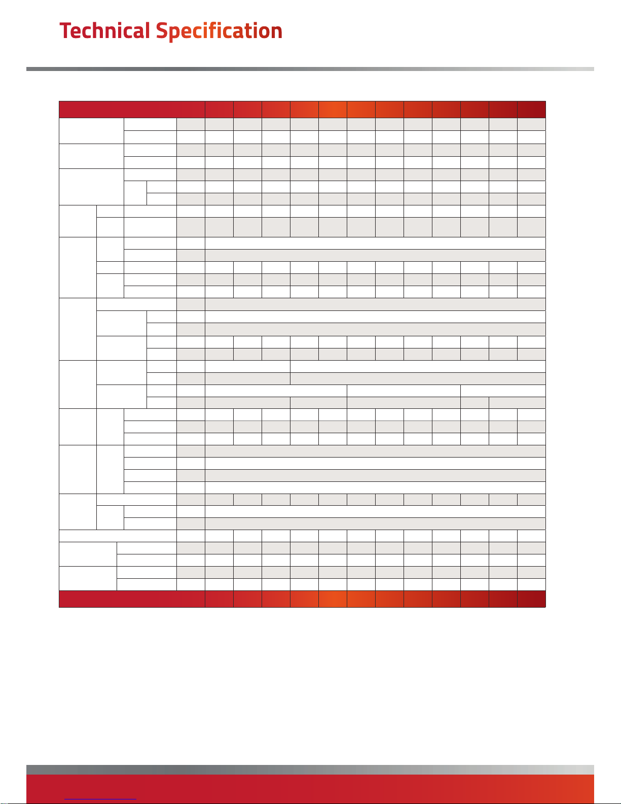
Model 15 20 25 35 40 45 50 60 70 90 120 140
Output (nominal)
High Fire (max)
kW 14.5 19.0 24.0 34.0 37.5 44.0 50.5 60.0 70.5 90.0 118.5 137.0
Low Fire (min)
kW 8.6 12.7 16.3 23.8 25.5 29.8 33.9 40.8 47.8 65.3 83.5 93.3
Input (nett CV)
High Fire (max)
kW 15.5 20.5 26.0 36.5 40.5 47.0 54.5 65.0 76.5 97.5 127.0 146.0
Low Fire (min) kW 9.53 14.07 18.16 26.08 28.17 32.46 37.41 45.07 52.91 71.65 90.83 101.16
Airflow
Volume
LNVx F/CCF/V m
3
/s 0.42 0.56 0.78 1.11 1.18 1.51 1.51 1.83 1.94 2.81 3.56 3.75
LNVx D
Min m
3
/s 0.42 0.56 0.78 1.11 1.18 1.51 1.51 1.83 1.94 2.81 3.56 3.75
Max m
3
/s 0.46 0.62 0.86 1.22 1.30 1.67 1.67 2.02 2.14 3.09 3.91 4.13
Airflow
Throw LNVx F m 10.0 14.0 20.0 28.0 30.0 35.0 35.0 38.0
42.0 44.0 45.0 45.0
Fan
Static
LNVx CCF Pa 220 320 220 N/A 150 250 250 250 250 180 290 250
Electrics
Supply
Standard V/ph/Hz 230/1/50
Optional* V/ph/Hz 400/3/50 *on Centrifugal Units Only. 3Ph units shown in brackets ()
LNVx F Run amp 0.40 0.45 0.52 1.14 0.85 1.53 1.57 2.30 2.20 3.06 4.35 4.45
LNVx
CCF
Start amp 5.0 8.5 13.3 N/A 18.0 26.3 26.3 29(16.5) 38(18) 31.0 40(14.9) 44(16.8)
Run amp 2.0 3.1 4.2 N/A 5.8 7.6 7.6 10(4.8) 11(5.3) 12.8 17(4.6) 20(4.9)
Fuel
Connection BSP/Rc ¾"
Nominal Inlet
Pressure
Nat Gas mbar 20.0
LPG mbar 37.0
Consumption
Nat Gas m
3
/h 1.64 2.17 2.75 3.86 4.29 4.97 5.77 6.88 8.10 10.32 13.44 15.45
LPG m
3
/h 0.63 0.83 1.06 1.52 1.66 1.90 2.20 2.65 3.16 4.01 5.10 5.90
Mounting
Height
LNVx F/Duo
Crossflow
Min m 2.5 3.0
Max m 3.0 5.0
LNVx V
Downflow
Min m
4.0 5.0 6.0
Max m 6.0 7.0 8.0 10.0 12.0
Overall
Dims
LNVx F
Height mm 430 500 570 532 720 684 684 760 912 810 975 1140
Width mm 997 997 997 1325 997 1325 1325 1325 1325 1950 1950 1950
Depth mm 800 869 819 918 839 938 938 915 915 938 915 915
Install
Clearance
LNVx F
Top mm 200
LH Side mm 200
RH Side mm 1000
Rear mm 400
Flue
Diameter mm Ø 80 80 80 100 100 100 100 130 130 130 130 130
Max
Length
Flue Only m 12
Room Sealed m 6
Combustion Air Spigot mm Ø 80 80 80 100 100 100 100 130 130 130 130 130
Noise Levels
LNVx F dB(A) 48 47 47 50 58 59 59 60 60 63 64 64
LNVx CCF dB(A) 55 55 54 N/A 60 60 61 62 62 66
67 67
Nett Weight
LNVx F kg 59.5 73.0 76.5 84.0 103 122 122 135 149 202 238 286
LNVx CCF kg 71.0 83.6 86.4 N /A 122 143 143 170 213 329 364 430
Model 15 20 25 35 40 45 50 60 70 90 120 140
Notes:
Fuel Consumption and input figures ba sed upon nett calorific values as
follows: Natural Gas (G20) nett CV 34.02 MJ/m
3
- Propane (G31) nett CV 88.00
MJ/m
3
• Heaters have efficiency levels which meet with the minimum
heater efficiency requirements of UK Part L Building Regulations.
• LNVx heaters comply with the seasonal efficiency and NOx
limits requirements of the Ecodesign regulation (EU) 2015/1188,
Directive 2009/125/EC – Lot 21 Tier 1
• Standard heaters configured as High/Low. Optional modulation
available.
• Air handling data is assessed at room ambient conditions
• Throw figures provide the distance to the point where the terminal
velocity degrades to 0.25m/s
• Dimensions, weights and clearance data in the table above refer
to LNVx F units only - for data on all other models refer to the
dimensions page and/or the installation instructions.
• Noise levels are applicable to standard LNVx F and LNVx V models
and are measured 5m from appliance in a free field.
• Motor kW, run and start amps apply to standard electrical supply as
stated. For optional data contact sales office.
• Optional 3 phase direct drive centrifugal blowers shown in italics
within brackets().
• Connection of combustion air duct is not required for ‘flue only’
applications.
• It is the responsibility of the installing contractor to ensure that
ductwork is correctly sized and balanced when installing LNVx
Centrifugal units.
Technical Specification
LNVx
Page 7
page no. 7 of 48
LNVx Range Users, Installation & Servicing Instructions Doc Ref M104 issue 1.0 Sep 2018.
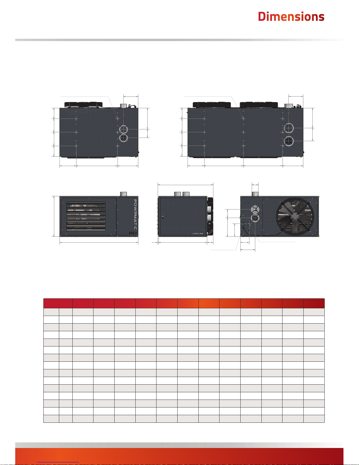
Dimensions
LNVx F- Freeblowing
Model
15 20 25 35 40 45 50 60 70 90 120 140
A mm 997 997 997 1325 997 1325 1325 1325 1325 1950 1950 1950
B mm 700 730 730 819 730 819 819 819 819 819 819 819
C mm 430 500 570 532 720 684 684 760 912 810 975 1140
DØ mm 80 80 80 100 100 100 100 130 130 130 130 130
E mm 248 268 268 357 268 357 357 357 357 337.5 337.5 337.5
F mm 198.5 248 318 225 446 320 325 325 476 457 622 787
G mm 120 120 120 142 142 142 142 220 220 220 220 220
H mm 317 317 317 347 317 347 347 347 347 347 347 347
J mm 450 450 450 700 450 700
700 700 700 662.5 662.5 662.5
K mm 230 230 230 278 230 278 278 278 278 278 278 278
L mm 800 869 819 918 839 938 938 915 915 938 915 915
M mm 217.5 217.5 217.5 247.5 217.5 247.5 251 237 237 247 247 247
N mm 117 117 117 145.5 117 145.5 145.5 145.5 145.5 90 90 90
P mm 175 172 245 220 285 221.5 221.5 298 373.5 412 413 481
Q mm 86 125 75 85 95 105 105 82 82 105 82 82
1
2
3
4
5
6
7
8
A
C
14 B
Q
L
N
M
M
M
P
F
G
D
K
J CRS
H
1
8
1
.
5
2
2
8
.
0
C
R
S
2
2
8
.
0
C
R
S
1
8
1
.
5
E
G
1
8
1
.
5
2
2
8
.
0
C
R
S
2
2
8
.
0
C
R
S
1
8
1
.
5
K
J CRS J CRS
H
E
G
SUSPENSION POINTS M10
SUSPENSION POINTS M10
GAS ENTRY POINT
ELEC ENTRY
Page 8
page no. 8 of 48
LNVx Range Users, Installation & Servicing Instructions Doc Ref M104 issue 1.0 Sep 2018.
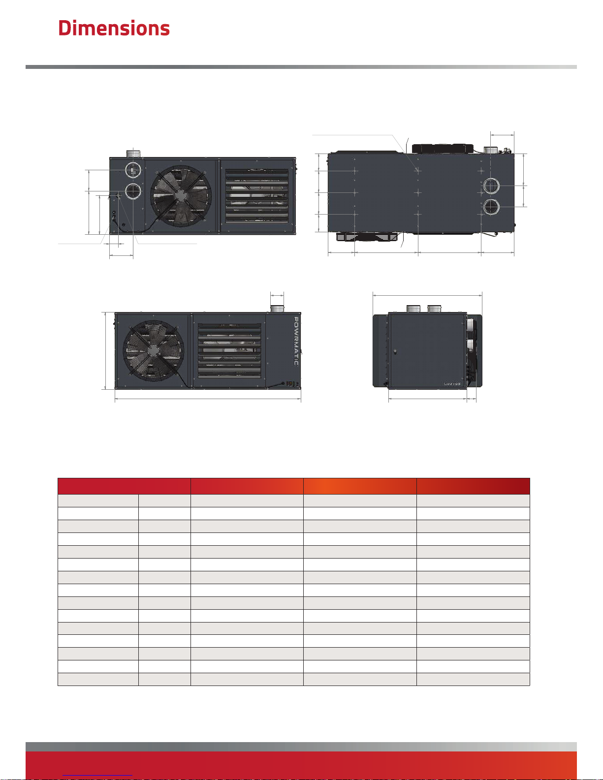
Dimensions
LNVx Duo- Axial Fan Bi-directional Units
Model
90 120 140
A mm 1950 1950 1950
B mm 819 819 819
C mm 810 975 1140
DØ mm 130 130 130
E mm 337.5 337.5 337.5
F mm 457 622 787
G mm 220 220 220
H mm 347 347 347
J mm 662.5 662.5 662.5
K mm 278 278 278
L mm 1150 1150 1150
M mm 247 247 247
N mm 90 90 90
P mm 412 413 481
Q mm 105 82 82
A
1
2
3
4
5
6
7
8
A
C
L
B
Q
P
F
G
N
M
ELEC ENTRY
GAS ENTRY POINT
E
G
M
H
J CRSJ CRS
K
1
8
1
.
5
2
2
8
.
0
C
R
S
2
2
8
.
0
C
R
S
1
8
1
.
5
M10 SUSPENSION POINTS
ØD
Page 9

page no. 9 of 48
LNVx Range Users, Installation & Servicing Instructions Doc Ref M104 issue 1.0 Sep 2018.
Dimensions
LNVx V - Axial Fan Downflow
Model
15 20 25 35 40 45 50 60 70 90 120 140
A mm 997 997 997 1325 997 1325 1325 1325 1325 1950 1950 1950
B mm 700 730 730 819 730 819 819 819 819 819 819 819
C mm 430 500 570 532 720 684 684 760 912 810 975 1140
DØ mm 80 80 80 100 100 100 100 130 130 130 130 130
E mm 248 268 268 357 268 357 357 357 357 337.5 337.5 337.5
F mm 198.5 248 318 225 446 320 325 325 476 457 622 787
G mm 120 120 120 142 142 142 142 220 220 220 220 220
H mm 289.5 289.5 289.5 319.5 289.5 319.5 319.5 319.5 319.5 319.5 319.5 319.5
J mm 260 260 260 385 260 385
385 385 385 460 460 460
K mm 202.5 202.5 202.5 250.5 202.5 250.5 250.5 250.5 250.5 250.5 250.5 250.5
L mm 820 885 835 934 855 954 954 929 929 954 929 929
M mm 217.5 217.5 217.5 247.5 217.5 247.5 251 237 237 247 247 247
N mm 117 117 117 145.5 117 145.5 145.5 145.5 145.5 90 90 90
P mm 175 172 245 220 285 221.5 221.5 298 373.5 412 413 481
1
2
3
4
5
6
7
8
A
E
G
D
C
+
3
0
C
+
3
0
K
J CRS J CRS
H
M
N
P
F
G
DROP ROD
SUSPENSION POINTS M10
ELEC ENTRY
GAS ENTRY POINT
K
J CRS J CRS J CRS
H
N
M
P
F
G
ELEC ENTRY
GAS ENTRY POINT
DROP ROD
SUSPENSION POINTS M10
B
+
6
5
A
B
L
C
M
Page 10
page no. 10 of 48
LNVx Range Users, Installation & Servicing Instructions Doc Ref M104 issue 1.0 Sep 2018.
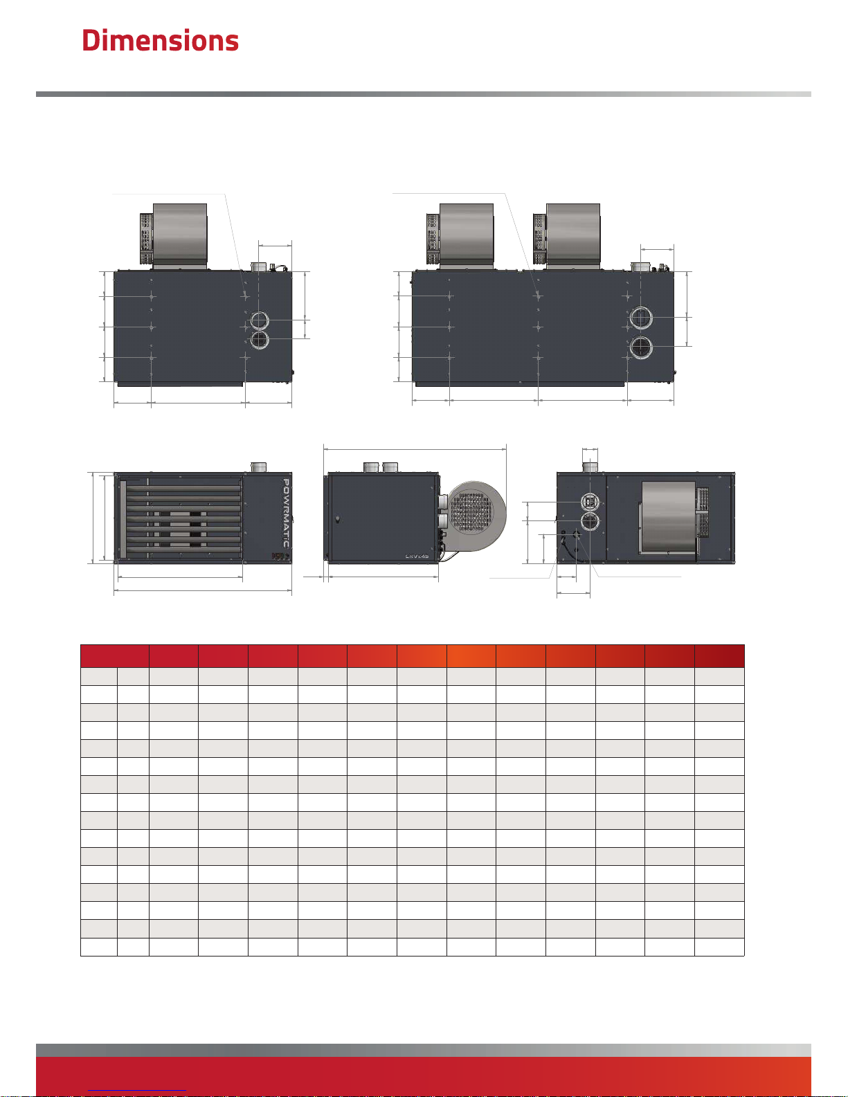
Dimensions
LNVx CCF- Centrifugal Close Coupled Fan Units
Model
15 20 25 35 40 45 50 60 70 90 120 140
A mm 997 997 997 N/A 997 1325 1325 1325 1325 1950 1950 1950
B mm 700 730 730 N /A 730 819 819 819 819 819 819 819
C mm 430 500 570 N/A 720 684 684 760 912 810 975 1140
DØ mm 80 80 80 N/A 100 100 100 130 130 130 130 130
E mm 248 268 268 N/A 268 357 357 357 357 337.5 337.5 337.5
F mm 198.5 248 318 N/A 446 320 325 325 476 457 622 787
G mm 120 120 120 N /A 142 142 142 220 220 220 220 220
H mm 317 317 317 N/A 317 347 347 347 347 347 347 347
J mm 450 450 450 N/A 450 700
700 700 700 662.5 662.5 662.5
K mm 230 230 230 N/A 230 278 278 278 278 278 278 278
L mm 1130 1205 1205 N/A 1275 1450 1450 1450 1450 1365 1450 1450
M mm 217.5 217.5 217.5 N/A 217.5 247.5 251 237 237 247 247 247
N mm 117 117 117 N/A 117 145.5 145.5 145.5 145.5 90 90 90
P mm 175 172 245 285 285 221.5 221.5 298 373.5 412 413 481
S mm 630 630 630 630 630 927 927 927 927 1552 1552 1552
T mm 376 446 516 666 666 631 631 707 858 757 922 1087
1
2
3
4
5
6
7
8
S
T
A
C
B
L
N
M
P
F
G
D
ELEC ENTRY
GAS ENTRY POINT
K
J CRS
H
1
8
1
.
5
2
2
8
.
0
C
R
S
2
2
8
.
0
C
R
S
1
8
1
.
5
E
G
M
SUSPENSION POINTS M10
E
G
M
1
8
1
.
5
2
2
8
.
0
C
R
S
2
2
8
.
0
C
R
S
1
8
1
.
5
K H
J CRS J CRS
SUSPENSION POINTS M10
35.0
Page 11
page no. 11 of 48
LNVx Range Users, Installation & Servicing Instructions Doc Ref M104 issue 1.0 Sep 2018.
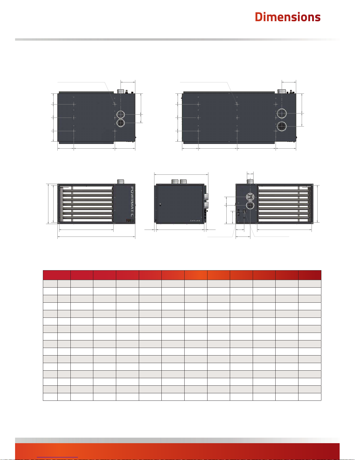
Dimensions
LNVx D Ducted Heat Module (No fan)
Model
15 20 25 40 45 50 60 70 90 120 140
A mm 997 997 997 997 1325 1325 1325 1325 1950 1950 1950
B mm 700 730 730 730 819 819 819 819 819 819 819
C mm 430 500 570 720 684 684 760 912 810 975 1140
DØ mm 80 80 80 100 100 100 130 130 130 130 130
E mm 248 268 268 268 357 357 357 357 337.5 337.5 337.5
F mm 198.5 248 318 446 320 325 325 476 457 622 787
G mm 120 120 120 142 142 142 220 220 220 220 220
H mm 317 317 317 317 347 347 347 347 347 347 347
J mm 450 450 450 450 700 700 700 700 662.5 662.5 662.5
K mm 230 230 230
230 278 278 278 278 278 278 278
L mm 804 834 834 834 924 924 924 924 924 924 924
M mm 217.5 217.5 217.5 217.5 247.5 251 237 237 247 247 247
N mm 117 117 117 117 145.5 145.5 145.5 145.5 90 90 90
P mm 175 172 245 285 221.5 221.5 298 373.5 412 413 481
S mm 630 630 630 630 927 927 927 927 1552 1552 1552
T mm 376 446 516 666 631 631 707 858 757 922 1087
1
2
3
4
5
6
7
8
S
T
A
C
B
L
P
N
M
GAS ENTRY POINT
ELEC ENTRY
E
G
M
E
G
M
1
8
1
.
5
2
2
8
.
0
C
R
S
2
2
8
.
0
C
R
S
1
8
1
.
5
K
J CRS
H
1
8
1
.
5
2
2
8
.
0
C
R
S
2
2
8
.
0
C
R
S
1
8
1
.
5
K
J CRS J CRS
H
S
T
D
SUSPENSION POINTS M10 SUSPENSION POINTS M10
F
G
35.035.0
Page 12
page no. 12 of 48
LNVx Range Users, Installation & Servicing Instructions Doc Ref M104 issue 1.0 Sep 2018.
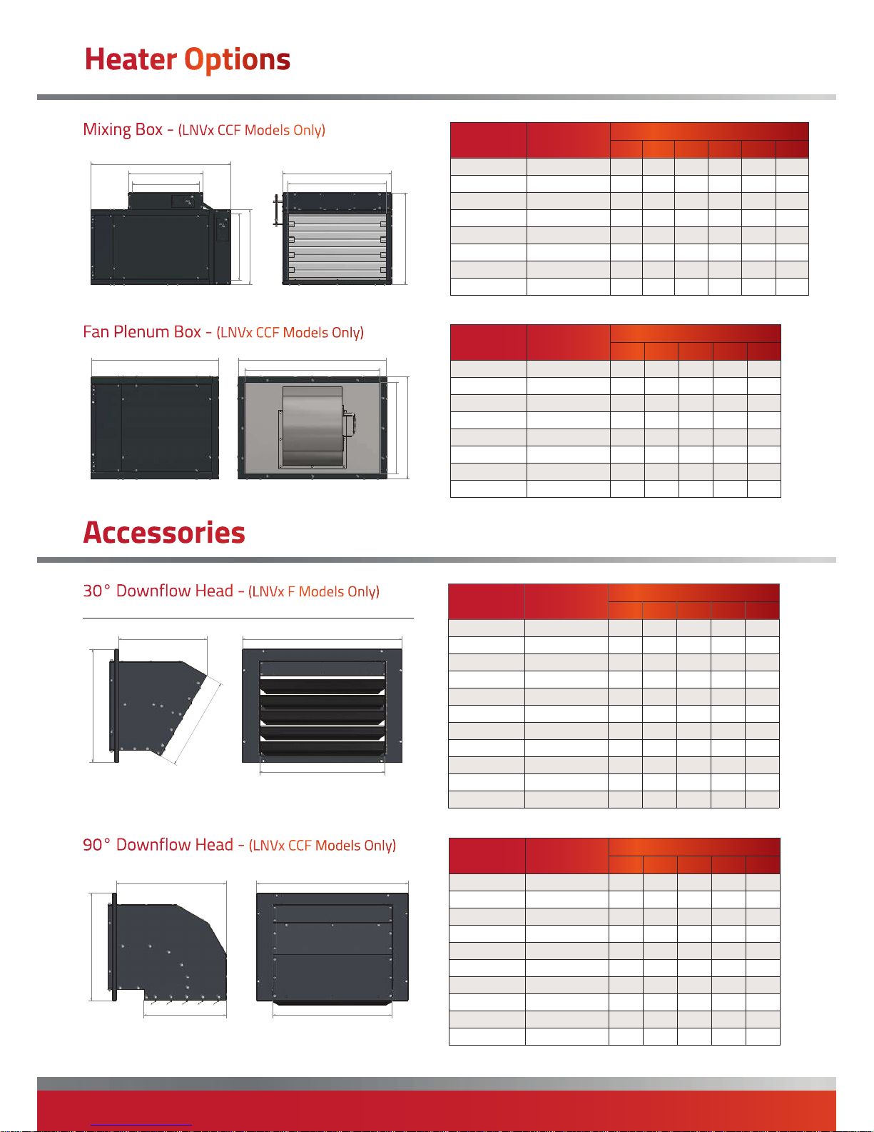
Fan Plenum Box - (LNVx CCF Models Only)
Mixing Box - (LNVx CCF Models Only)
Model Part Number
Dimensions (mm)
A B C D E F
LNVx 15/20/25 LNVx15/MB 1160 730 696 600 498 570
LNVx 40 LNVx40/MB 1160 880 696 600 648 720
LNVx 45/50 LNVx50/MB 1285 845 994 900 613 685
LNVx 60 LNVx60/MB 1285 920 994 900 688 760
LNVx 70 LNVx70/MB 1285 1070 994 900 838 910
LNVx 90 LNVx90/MB 1285 970 1620 1526 738 810
LNVx 120 LNVx120/MB 1285 1135 1620 1526 903 975
LNVx 140 LNVx140/MB 1455 1300 1620 1526 1068 1140
1
2
3
4
5
6
7
A
E
F
C
D
B
E
F
Model Part Number
Dimensions (mm)
A B C D E
LNVx 15/20/25 LNVx15/FS 750 696 570 480 622
LNVx 40 LNVx40/FS 750 696 720 630 622
LNVx 45/50 LNVx50/FS 850 994 685 595 920
LNVx 60 LNVx60/FS 850 994 760 670 920
LNVx 70 LNVx70/FS 850 994 910 820 920
LNVx 90 LNVx90/FS 850 1620 810 720 1546
LNVx 120 LNVx120/FS 850 1620 975 885 1546
LNVx 140 LNVx140/FS 850 1620 1140 1050 1546
Accessories
30° Downflow Head - (LNVx F Models Only)
90° Downflow Head - (LNVx CCF Models Only)
1
2
3
4
5
A
B
E
C
D
D
C
E
Heater Options
1
2
3
4
5
A
B
E
C
D
D
E
C
B
A
D
D
E
C
C
E
1
2
3
4
5
6
7
E
B
D
C
A
1
2
3
4
E
B
D
C
Model Part Number
Dimensions (mm)
A B C D E
LNVx 15 LNVx15-30DH 376 305 630 280 494
LNVx 20 LNVx20-30DH 446 340 630 350 494
LNVx 25 LNVx25-30DH 516 375 630 420 494
LNVx 35 LNVx35-30DH 478 340 927 350 660
LNVx 40 LNVx40-30DH 666 450 630 570 494
LNVx 45/50 LNVx50-30DH 631 415 927 500 660
LNVx 60 LNVx60-30DH 707 415 927 500 660
LNVx 70 LNVx70-30DH 858 480 927 630 660
LNVx 90 LNVx90-30DH 757 450 757 570 660
LNVx 120 LNVx120-30DH 922 520 757 710 660
LNVx 140 LNVx140-30DH 1087 590 757 850 660
Model Part Number
Dimensions (mm)
A B C D E
LNVx 15 LNVx15-90DH 376 430 630 280 494
LNVx 20 LNVx20-90DH 446 500 630 350 494
LNVx 25 LNVx25-90DH 516 570 630 420 494
LNVx 40 LNVx40-90DH 666 720 630 570 494
LNVx 45/50 LNVx50-90DH 631 650 927 500 660
LNVx 60 LNVx60-90DH 707 650 927 500 660
LNVx 75 LNVx70-90DH 858 780 927 630 660
LNVx 90 LNVx90-90DH 757 720 757 570 660
LNVx 120 LNVx120-90DH 922 860 757 710 660
LNVx 140 LNVx140-90DH 1087 1000 757 850 660
Page 13
page no. 13 of 48
LNVx Range Users, Installation & Servicing Instructions Doc Ref M104 issue 1.0 Sep 2018.
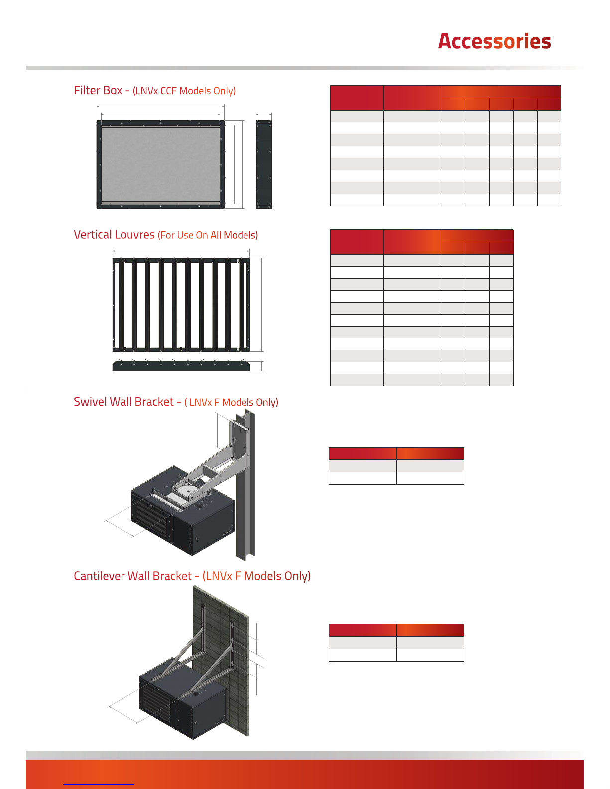
Swivel Wall Bracket - ( LNVx F Models Only)
Cantilever Wall Bracket - (LNVx F Models Only)
Notes:
- Dimensions for the swivel and cantilever brackets remain the same for all LNVx
models
- Swivel Brackets can not be used with double units
Model Part Number
LNVx 15 - 70 LNVx15-70WB
LNVx 90 - 140 LNVx90-140WB
Model Part Number
LNVx 15 - 70 LNVx15-70SWB
LNVx 90 - 140 N/A
Vertical Louvres (For Use On All Models)
Model Part Number
Dimensions (mm)
A B C
LNVx 15 LNVx15-VL 630 376 65
LNVx 20 LNVx20-VL 630 446 65
LNVx 25 LNVx25-VL 630 516 65
LNVx 35 LNVx35-VL 927 478 65
LNVx 40 LNVx40-VL 630 666 65
LNVx 45/50 LNVx50-VL 927 631 65
LNVx 60 LNVx60-VL 927 707 65
LNVx 70 LNVx70-VL 927 858 65
LNVx 90 LNVx90-VL 757 757 65
LNVx 120 LNVx120-VL 757 922 65
LNVx 140 LNVx140-VL 757 1087 65
Filter Box - (LNVx CCF Models Only)
1
2
3
4
A
D
C
B
E
Model Part Number
Dimensions (mm)
A B C D E
LNVx 15/20/25 LNVx15-FB 696 570 120 626 500
LNVx 40 LNVx40-FB 696 720 120 626 650
LNVx 45/50 LNVx45-FB 994 685 120 924 615
LNVx 60 LNVx60-FB 994 760 120 924 690
LNVx 70 LNVx70-FB 994 910 120 924 840
LNVx 90 LNVx90-FB 1620 810 120 1550 740
LNVx 120 LNVx120-FB 1620 975 120 1550 905
LNVx 140 LNVx140-FB 1620 1140 120 1550 1070
Accessories
1
2
3
4
5
6
B
A
1
2
3
4
5
6
C
B
A
1
2
3
4
5
6
4
7
5
.
0
H
E
A
T
E
R
C
R
S
H
E
A
T
E
R
C
R
S
3
0
0
.
0
2
0
0
.
0
3
0
0
.
0
1
2
3
H
E
A
T
E
R
C
R
S
3
0
0
.
0
2
0
0
.
0
3
0
0
.
0
Page 14
page no. 14 of 48
LNVx Range Users, Installation & Servicing Instructions Doc Ref M104 issue 1.0 Sep 2018.
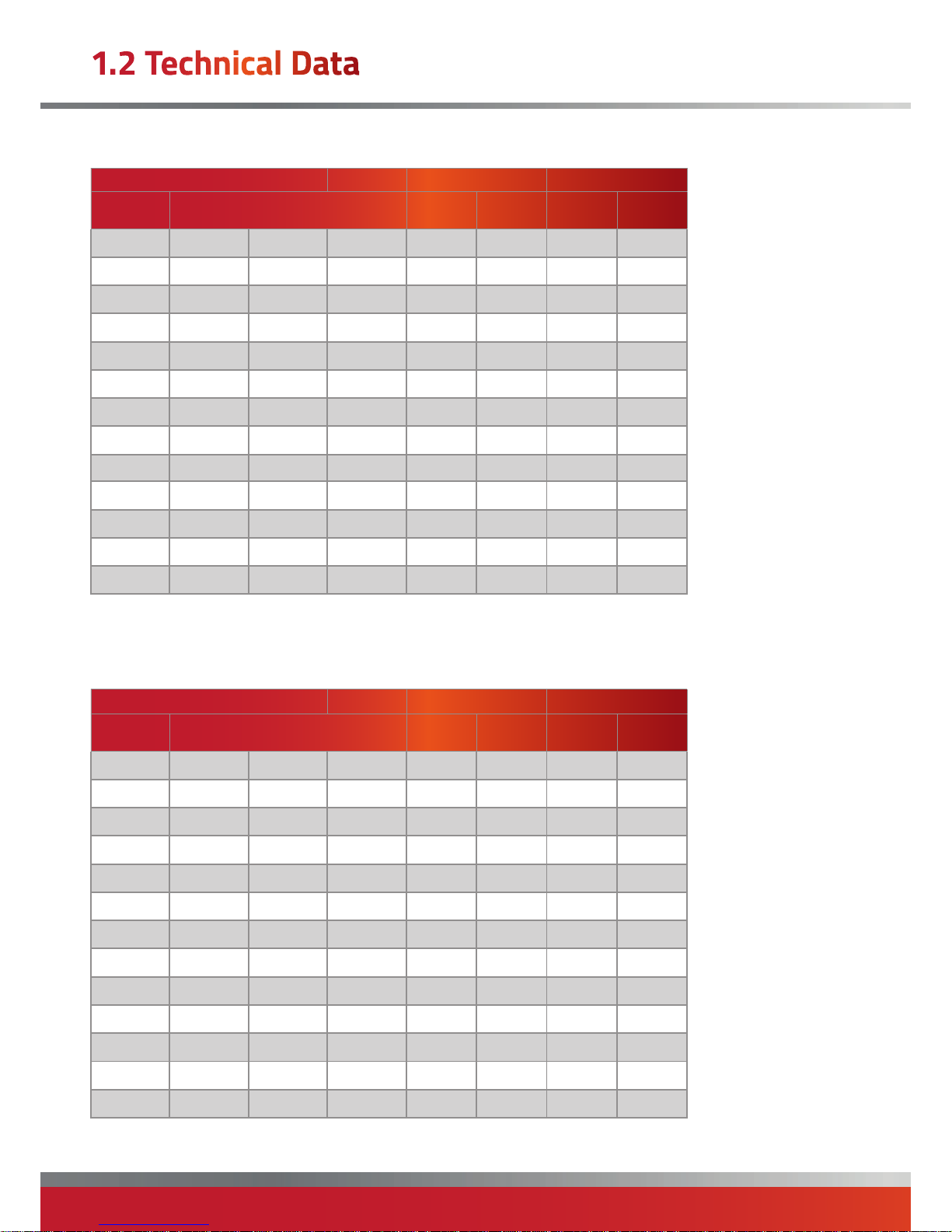
(All variants)
High Fire Low Fire
Injectors
Burner
Pressure
Gas Rate
Burner
Pressure
Gas Rate
MODEL No. Size (mm) Marked mbar m³/h mbar m³/h
LNVx15 3 1.94 500 13 .1 1.64 5.0 1.01
LNVx20 4 1.94 500 12.3 2 .17 6.0 1.49
LNVx25 5 1.94 500 13.5 2.75 6.5 1.92
LNVx35 5 2.26 580 13.2 3.86 5.8 2.76
LNVx40 8 1.94 500 12.3 4.29 6.0 2.98
LNVx45 10 2.54 750 7. 4 4.97 3.5 3.43
LNVx50 10 2.54 750 9.5 5.77 4.5 3.96
LNVx60 8 2.54 750 10.6 6.88 5.2 4.77
LNVx70 10 2.54 750 9.4 8.1 0 4.6 5.60
LNVx90 8 3.5 1500 6.0 10.32 3.0 7.5 8
LNVx120 10 3.5 1500 6.7 13.44 3.3 9.61
LNVx140 12 3.5 1500 6.2 15.45 2.9 10.7
Injector Sizes & Burner Pressures - Natural Gas - Group H - G20 Net CV (Hi = 34.02MJ/m³)
Nominal Inlet
Pressure = 20mbar
Minimum Inlet
Pressure = 17.5mbar
(All variants)
High Fire Low Fire
Injectors
Burner
Pressure
Gas Rate
Burner
Pressure
Gas Rate
MODEL No. Size (mm) Marked mbar m³/h mbar m³/h
LNVx15 3 1.36 240 21.3 0.6 8.0 0.39
LNVx20 4 1.36 240 19.8 0.8 9.5 0.57
LNVx25 5 1.36 240 21.3 1.1 10.2 0.74
LNVx35 5 1.6 160 22.5 1.5 11.5 1.1
LNVx40 8 1.36 240 19.5 1.7 9.6 1.17
LNVx45 10 1.6 160 18.4 1.9 8.8 1.31
LNVx50 10 1.6 160 24.2 2.3 12.2 1.6
LNVx60 8 1.6 160 25.4 2.6 12.3 1.85
LNVx70 10 1.6 160 22.9 3.2 11.3 2.15
LNVx90 8 2.26 580 13.5 4.0 7. 2 2.91
LNVx120 10 2.26 580 14.6 5 .1 7.2 3.69
LNVx140 12 2.26 580 13.4 5.9 6.4 4.11
Injector Sizes & Burner Pressures - Propane G31 Net CV (Hi = 88.00MJ/m³)
Nominal Inlet
Pressure = 37mbar
Minimum Inlet
Pressure = 25mbar
1.2 Technical Data
Page 15

page no. 15 of 48
LNVx Range Users, Installation & Servicing Instructions Doc Ref M104 issue 1.0 Sep 2018.
1.3.1. Related Documents
All LNVx heaters comply with the following European
Directives:
Energy Related Product Directive: 2009/125/EC*
Gas Appliance Directive: 2009/142/EC
Electromagnetic Compatibility Directive: 2004/108/EC
Low Voltage Directive: 2006/95/EC
Machinery Directive: 2006/42/EC
Air heater(s) must be installed in accordance with BS6230
and BS5440 plus any relevant requirements of local and
national building codes. * where appropriate.
1.3.2 Location
Powrmatic LNVx units are designed to operate within an
ambient temperature range of -10 to 25°C.
LNVx heaters can be installed in several ways: i)
suspended from ‘drop rods’ via purpose designed M10
suspension fixing points on the heater, ii) attached to our
optional wall support brackets or iii) positioned on a level,
non-combustible base. In all cases, it is important that all
supporting structures have been assessed with regard to
the relevant weight loadings.
Consideration should be given to flue routes and points of
exit, gas, electrical and control connections. Consideration
should also be given to the throw characteristics of the
heater, issues of public access and siting of environmental
control stations and/or remote temperature sensors
where the position needs to be representative of the zone
temperature to which they refer.
Where the location of the air heater is such that it might
suffer external mechanical damage e.g. from overhead
cranes, fork lift trucks, it must be suitably protected.
Heaters should not be installed in hazardous areas or
areas where there is a foreseeable risk of flammable
or corrosion inducing particles, gases or vapours being
drawn into the combustion air or main fan circuits.
Areas where special consideration or advice may be
required could include but is not limited to –
• Where de-greasing solvents are present, even in
minute concentrations
• Where paint spraying is carried out
• Where styrenes or other laminating products are
used
• Where airborne silicone is present
• Where petrol engine vehicles are stored or
maintained
• Where dust is present (i.e. wood working or
joinery shops)
• Where high levels of extract persist.
Installation in such areas may be possible under specific
conditions. Please consult our Technical Department for
further information.
1.3.2.1 Sizing of the heater
The heater should be correctly sized for the area that it is
heating, Full calculations need to be preformed to ensure
the correct KW output heater is fitted (CIBSE elemental
methodology can be used, or the Powrmatic Technical
Department can provide guidelines).
1.3.3 Electrical Supply
Wiring external to the air heater must be installed in
accordance with the I.E.E. Regulations for Electrical
Installations and any local regulations which apply.
All standard heaters are supplied by 230V - 1ph, 50Hz.
The method of connection to the main electricity supply
must:-
- facilitate the complete electrical isolation of the unit(s)
via a suitable fused isolator (see section 2.4.5 for ratings)
- be in a readily accessible position adjacent to the unit(s)
- serve only the unit(s)
- have a contact separation of at least 3mm in all poles.
See the accompanying wiring diagram for the heater
electrical connections
LNVx CCF and fan/silencer units can also be supplied for
400V 3N, 50Hz.
1.3.4 Gas Supply
A servicing valve and union to facilitate servicing must
be fitted to the gas inlet pipe work of the heater. The
gas supply must be completed in solid pipe work and be
adequately supported.
Heaters suspended by drop rods, straps or chains must
have a flexible connection as the final link between the
gas supply pipe work and the heater. Sufficient slack
must be left in the connection to take account of normal
movement of the heater.
WARNING: When completing the final gas
connection to the heater do not place undue
strain on the gas pipe work of the heater.
1.3.4.1 Service Pipes
The local gas undertaking should be consulted at the
installation planning stage in order to establish the
availability of an adequate supply of gas to suit the
1.3 General Requirements
Page 16

page no. 16 of 48
LNVx Range Users, Installation & Servicing Instructions Doc Ref M104 issue 1.0 Sep 2018.
building requirements. An existing service pipe must not
be used without prior consultation with the local gas
undertaking.
1.3.4.2 Meters
An existing meter should be checked, preferably by the
gas undertaking, to ensure that the meter is adequate
to deal with the total rate of gas supply required by all
connected equipment.
1.3.4.3. Installation Pipes
Installation pipes should be fitted in accordance with IGE/
UP/2. Pipe work from the meter to the air heater must be
of adequate size.
Do not use pipes of a smaller size than the inlet gas
connection of the heater.
The complete installation must be tested for soundness
as described in the above Code.
1.3.5 Flue System
Only flue systems supplied through Powrmatic Ltd may
be used with LNVx units. Several configurations of flue
and combustion air ducts are available.
The flue must terminate in a freely exposed position and
be sited to prevent the products of combustion entering
any opening in a building in such concentration as to be
prejudicial to health or a nuisance.
Type B22 Installation.
Type C12 or C32 Installation.
1.3.6 Ventilation Requirements
Type B flued installations.
Where LNVx heaters are installed within the heated
space (ie not in a plant room or an enclosure) and having
a building design air change rate of greater than 0.5/h,
additional provision for ventilation is not required.
If the building design air change rate is less than 0.5/h,
additional provision for natural or mechanical ventilation
is required. These being:
• Natural Ventilation:
Grilles having a free area of at least 2cm² per kW of rated
heat input shall be provided at low level i.e. below the level
of the heater flue connection.
• Mechanical Ventilation:
Must ensure that the space air change rate is at least
0.5/h, must be of the ‘input’ type and interlocked to
ensure the heaters cannot work if the input system is not
working.
Type B flued installations.
Where LNVx heaters are installed in a plant room or
an enclosure (i.e. not within the heated space) having
combustion air drawn directly from the room and
connected to a flue that evacuates the products of
combustion directly from the room additional provision
for natural or mechanical ventilation is required.
Option 2:
Combustion Air Entry
(fitted with inlet gri lle)
Op tion 1:
Combustion Air Entry
(fitted with inlet gri lle)
Combustion
Air Socket
1.3 General Requirements
Page 17

page no. 17 of 48
LNVx Range Users, Installation & Servicing Instructions Doc Ref M104 issue 1.0 Sep 2018.
Typ e B22 Installation (these refer to section 2.2 of
these instructions)
Air vents shall be permanently open.
In all cases figures are per heater installed.
For multi heater installations the appropriate
values for each heater must be added together
Typ e C
12 or C32 Installation (these refer to section 2.2
of these instructions)
Air vents shall be permanently open.
Figures are for heaters in plant rooms or
enclosures ONLY
In all cases figures are per heater installed.
For multi heater installations the appropriate
values for each heater must be added together.
LNVx
Input
kW
In the
heated
space
In a plant room,
ventilation to
outside
In an enclosure,
ventilation to
outside
In the
heated
space
Ventilation is to a
room or internal
space
Ventilation is to a
outside air
Low level
grille.
Free area
cm²
Low level
grille.
Free area
cm²
High level
grille.
Free area
cm²
Low level
grille.
Free area
cm²
High level
grille.
Free area
cm²
Free area
grille cm²
Low level
grille.
Free area
cm²
High level
grille.
Free area
cm²
Low level
grille.
Free area
cm²
High level
grille.
Free area
cm²
15 15.5 31.0 62.0 31.0 155.0 77. 5 n/a 155.0 155.0 77.5 7 7. 5
20 20.5 41. 0 82.0 41.0 205.0 102.5 n/a 205.0 205.0 102.5 102.5
25 26.0 52.0 104.0 52.0 260.0 130.0 n/a 260.0 260.0 130.0 130.0
35 36.5 73.0 146.0 73.0 365.0 182.5 n/a 365.0
365.0 182.5 182.5
40 40.5 81.0 162.0 81.0 405.0 202.5 n/a 405.0 405.0 202.5 202.5
45 47.0 94.0 188.0 94.0 470.0 235.0 n/a 470.0 470.0 235.0 235.0
50 54.5 109.0 218.0 109.0 545.0 272.5 n/a 545.0 545.0 272.5 272.5
60 65.0 130.0 260.0 130.0 650.0 325.0 n/a 650.0 650.0 325.0 325.0
70 76.5 153.0 306.0 153.0 765.0 382.5 n/a 765.0 765.0 382.5 382.5
90 97.5 195.0 390.0 195.0 975.0 487. 5 n/a 975.0 975.0 4 8 7. 5 4 8 7.5
120 127.0 254.0 508.0 254.0 1270.0 635.0 n/a 1270.0 1270.0 635.0 635.0
140 146.0 292.0 584.0 292.0 1460.0 730.0 n/a 1460.0 1460.0 730.0 730.0
These being:
• Natural Ventilation:
There must be permanent air vents communicating
directly with the outside air, at high level and at low level.
Plant Rooms
Low level (inlet) 4cm²/kw of total rated net heat input
High level (outlet) 2cm²/kw of total rated net heat input
Enclosures
Low level (inlet) 10cm²/kw of total rated net heat input
High level (outlet) 5cm²/kw of total rated net heat input
• Mechanical Ventilation:
The minimum flow rate of ventilation shall be 4.14m³/h
per kilowatt of total rated heat input.
Type C flued installations.
Where LNVx heaters are Installed within the heated
space (i.e. not in a plant room or an enclosure) having
combustion air ducted to the appliance and combustion
products ducted to the outside air, NO additional
provision for the supply of either combustion air or for
combustion products dilution or additional provision for
the supply of air is necessary.
Type C flued installations.
Where LNVx heaters are installed in a plant room or
an enclosure (i.e. not within the heated space) having
combustion air ducted to the appliance and combustion
products ducted to the outside, air vents shall be
provided and be permanently open.
To room or internal space
Low level (inlet) 10cm²/kw of total rated net heat input
High level (outlet) 10cm²/kw of total rated net heat input
Direct to outside air
Low level (inlet) 5cm²/kw of total rated net heat input
High level (outlet) 5cm²/kw of total rated net heat input.
1.3 General Requirements
Page 18

page no. 18 of 48
LNVx Range Users, Installation & Servicing Instructions Doc Ref M104 issue 1.0 Sep 2018.
1.3.7 Air Distribution System
Where LNVx F units are required to cover a large floor
area, and in buildings with high roof or ceiling heights
Calecon thermal economiser units may be considered to
ensure even heat distribution and minimise stratification.
Care should be taken to avoid impeding the air throw with
racking, partitions, plant or machinery etc. Various outlet
configurations are available as optional extras to modify
the air throw pattern to suit particular site conditions.
For LNVx CCF units, the duct work must comply to current
regulations and be correctly calculated to match the
particular heaters resistance and air flow.
A full and unobstructed return air path to the air heater(s)
must be provided.
If the air heater(s) are installed in a plant room, the return
air intake(s) and the warm air outlet(s) from the heater(s)
must be fully ducted, into and out of the plant room to
avoid interference with the operation of the heater.
The openings in the structure of the plant room/enclosure
through which the ducting passes must be fire stopped.
Care must be taken to ensure that return-air intakes are
kept clear of sources of smells and fumes, and where
there is any possibility of pollution of the air by dust,
shavings etc., precautions must be taken to prevent
contamination.
If necessary, suitable barrier rails should be provided to
prevent any combustible material being placed within
900mm of the outlets.
Model Air Volume m³/h Maximum Duct Resistance (Pa)
LNVx15CCF 1500 220
LNVx20CCF 2020 320
LNVx25CCF 2808 220
LNVx40CCF 4250 150
LNVx45CCF 5450 250
LNVx50CCF 5450 250
LNVx60CCF 6600 250
LNVx70CCF 9200 250
LNVx90CCF 10100 180
LNVx120CCF 128 0 0 250
LNVx140CCF 13500 250
1.3.7.1 Ducting Requirements
LNVxCCF Heater Unit
It is recommended that you have a
minimum of 2000mm from the heater
outlet prior to any restriction
Airflow
1.3 General Requirements
Page 19

page no. 19 of 48
LNVx Range Users, Installation & Servicing Instructions Doc Ref M104 issue 1.0 Sep 2018.
A
B
C
D
E
R/H Side Views
LNVx CCF
LNVx Duo
Front View
E
R/H Side Views
2.1.1 Fitting space requirement
LNVx F / CCF
Front View
LNVx V LNVx Duo
A
B
C
E
D
D
C
LNVx F
E
2.1 Fitting the Unit
Page 20

page no. 20 of 48
LNVx Range Users, Installation & Servicing Instructions Doc Ref M104 issue 1.0 Sep 2018.
Distance from outside of heater to closest obstacle Distance
A RHS Clearance (when viewed at front of heater) mm 1000
B LHS Clearance (when viewed at front of heater) mm 200
C Top of heater mm 200
D Rear of heater (dependent on flue system) mm 400
E
Recommended mounting heights
(floor level to underside of unit)
LNVx15F-30F / Duo M 2.5-3.0
LNVx35F-140F / Duo M 3.0-5.0
LNVx D M N/A
LNVx15V M 3.0
LNVx20-30V M 4.0-6.0
LNVx40V M 4.0-7.0
LNVx45-70V M 5.0-8.0
LNVx90V M 6.0-10.0
LN Vx120/14 0V M 6.0-12.0
For multi air heater installations the following minimum distances between units must be observed
Between units, side to side/back to back M 3.0
Note: All models must not be installed at a
height of less than 2.5m to the base of the
unit.
Note: For LNVx D units the normal air flow
direction is from right to left when viewing the
heater from the burner/controls end with the
fan unit upstream.
Note: The minimum clearances must be
observed for installation and servicing.
Warning: Any combustible material adjacent
to the air heater and the flue system must
be so placed or shielded as to ensure that its
temperature does not exceed 65 °C.
Warning: When LNVx modular components
are used in conjunction with the heater each
component must be individually supported.
Note: The access door to the controls section
may be removed to improve access. Open the
door to 90°, remove the earth cable at the
bottom, and then lift the door vertically
upwards to disengage the hinge plates. Refit in reverse
order. Ensure that the earth cable is refitted.
2.1.2 Suspending the heater
The air heater may be installed either:
a) suspended from suitable vertical drop rods
(recommended maximum length is 1.8m).
b) on specifically designed cantilever brackets from a non
combustible wall.
c) on a level noncombustible surface. The surface must
not extend past the front edge of LNVx F heaters.
The method of installation must be capable of adequately
supporting the weight of the unit (See section 1.2) and
any ancillary equipment. Before installing the heater
the existing structure must be inspected to ensure it is
suitable. All supports should be protected against the
effects of rust or corrosion.
Raise the heater up to the point of installation using
suitable and safe means and connect to the means of
suspension.
Note: Each heater is provided with additional
central suspension points (suspension points
running along the front and back are for
permanent connection, suspension points
running left to right in the centre are for temporary
support) that can be used to provide temporary support,
using suitable means, whilst the unit is being installed.
Under no circumstances must these points be used as the
final means of suspension.
2.1 Fitting the Unit
Page 21

page no. 21 of 48
LNVx Range Users, Installation & Servicing Instructions Doc Ref M104 issue 1.0 Sep 2018.
Temporary
supports
Threaded drop rods must have lock nuts fitted that are
tightened down onto the 10mm fixings in the heater.
All thread rod
Locknuts
Suspension
point
Recommended maximum drop rod length is 1.8m.
Permanent
suspension
supports
If reducing noise levels is important the heater should be
insulated from the structure by installing it on suitable
anti-vibration mountings. In all such cases and when the
heater is suspended it is essential that all gas, duct, and
electrical connections to the heater are made with flexible
connections to maintain continuity of connection.
2.1.3 Air Distribution System
2.1.3.1 General
LNVx Duo discharges air in two directions, significantly
enhancing the effective coverage of the heater and
leading to a more even warmth distribution especially
within modern well insulated buildings. This in-turn offers
a potential saving on both capital and installation costs.
LNVx D and LNVx CCF models are designed for use
with duct work to more precisely define the point of air
delivery, and /or provide ducted return air or ducted fresh
air inlet. All ducting must be independently supported of
the air heater. Joints and seams of supply ducts and joints
between LNVx ancillary components must be securely
fastened and made airtight using appropriate sealants
or sealing strips. If required the duct work should be
insulated to reduce heat loss.
2.1.3.2 Noise Reduction
Ducting should be connected to the heater spigots via an
airtight flexible coupling of noncombustible material.
Before fitting the coupling it must be ensured that a
minimum clearance of approximately 15mm will be
maintained between the ends of the ducting and the
heater spigots.
Sound attenuators may be fitted in inlet and outlet ducts
to reduce airborne fan noise. If sound attenuators are
used then these must be factored into the total static
resistance of the ductwork. Materials used in outlet sound
attenuators must be capable of withstanding 100°C air
temperature without any deterioration.
2.1.4 Room Thermostat Siting
The room thermostat should be fitted at a point which
will be generally representative of the heated area as
far as temperature is concerned. Draughty areas, areas
subjected to direct heat e.g. from the sun, and areas
where the air movement is relatively stagnant e.g. in
recesses, should be avoided. The thermostat should be
mounted approximately 1.5m from the floor.
Any room thermostat, frost thermostat, time clock etc.
must be suitable for switching 230V, 5A and must be of
the 'snap action' type to minimise contact bounce.
For electrical connections of external controls see section
2.5 or the accompanying wiring diagram.
2.1 Fitting the Unit
Page 22

page no. 22 of 48
LNVx Range Users, Installation & Servicing Instructions Doc Ref M104 issue 1.0 Sep 2018.
The minimum distance between surfaces of the flue pipe
and any surfaces made from combustible materials is
300mm. If it is necessary for the flue pipe to pass through
a structure made from combustible materials a metal
sleeve must be used so that the minimum clearance of
300mm is maintained.
The flue and combustion air ducts supplied with the
heater are capable of withstanding their own weight
over the allowable flue lengths. Wall bands and bracing
brackets, or equivalent, must be used to provide lateral
stability and should be used at centres not exceeding 2.5
metres.
All models are supplied as standard with a rear flue
outlet and the flue outlet and combustion air sockets
temporarily fitted.
2.2.1 Conversion to Top Flue Outlet
1. Remove the two blanking plates from the flue /
combustion air openings at the top of the unit.
2. Remove the four screws from the exhaust fan outlet
flange.
3. Remove the screws securing the fan mounting box to
the exhaust header plate.
4. Remove fan assembly and rotate the assembly 90°
anticlockwise.
5 Refit the fan assembly to the exhaust header plate
ensuring that the gasket is not damaged, if necessary
replace or make good with silicon sealant.
6. Secure the exhaust fan outlet flange to the underside of
the top panel and fit the blanking plates to the rear panel.
2.2.2. Fitting Flue/Combustion Air Sockets
1. Apply a bead of silicon sealant around the face of the
flange on the exhaust fan outlet tube that can be seen
from the outside of the heater. Place the flue socket on
the outside of the heater to mate with this flange and
clamp the two flanges together, on either side of the
heater panel using the screws provided. Ensure that the
silicon sealant has sealed between the two flanges.
2. Apply silicon sealant and refit blanking plates as
required to seal unused panel holes.
2.2.3. General Requirements
See Figures 1a to 2b for the different types of flue
installation. In all cases the flue outlet socket must be
connected via the provided flue system to outside air.
The maximum permitted length of flue system is 6m, or
12m if the flue outlet only is used. If an offset is required
two sets of 45° bends should be used each set being
equivalent to 0.5m of flue length. 90° bends may be used
but each set will be equivalent to 1.0m of flue length.
All outer joints must be finished with the provided locking
bands. A smear of silicon grease to the inside of sockets
will assist in fitting components together. All flue and
combustion air ducts must be supported independently
of the air heater. The flue or flue/combustion air terminal
must not be installed so as to be less than:
- 300mm below an opening e.g. window, air brick etc.
- 200mm below eaves or gutter.
- 300mm from an internal or external corner.
- 1200mm from a surface facing the terminal.
- 1500mm vertically from another terminal on the same
wall.
- 300mm horizontally from another terminal on the same
wall.
- 2000mm from ground level.
2.2.4. Installation of Flue System
Note: A terminal guard, as supplied by
Powrmatic Ltd, must be fitted to horizontal
flue terminals.
Notes for all systems.
i) Final overall length of adjustable
disconnection piece must be between 360 -
415m m .
ii) 45° offsets may be used if required. Each set is
equivalent to 0.5m of flue length.
iii) Where LNVx heaters are used in clean environments it
is permissible to take the combustion air directly from the
heated space.
2.2.4.1. Horizontal System - Rear Outlet
Note: If the outlet is required to the side of the
unit 90° bends may be fitted directly onto the
inlet/outlet spigots on the heater.
1. Locate the position of the flue terminal, allowing for
a slight gradient running down from the heater to the
terminal of 2° - 3° and cut a hole to suit.
2. Fit the flue terminal, securing via the wall plate and
2.2 Flue/Combustion Air Duct System
Page 23

page no. 23 of 48
LNVx Range Users, Installation & Servicing Instructions Doc Ref M104 issue 1.0 Sep 2018.
weather with silicon sealant or similar.
3. Fit the twin to concentric adapter to the terminal
section and extend the flue and combustion air ducts to
the heater using straight lengths.
Fit an adjustable length prior to the unit, to facilitate flue
disconnection for servicing. Extend the adjustable lengths
to make the final connection to the appropriate heater
inlet/outlet spigots.
4. Ensure that internal silicon sealing rings are in place and
that all tubes are pushed fully home. Secure concentric
lengths with the locking bands provided.
Fig 1a. Individual system - Type C12 horizontal
Flue Socket
Adjustable Lengths
Lengths
Terminal
Combustion Air Socket
Single to Twin Adaptor
Maximum 6m, Minimum 980mm
2.2.4.2. Vertical System - Top Outlet
1. Locate the position of the flue terminal cut a hole in the
roof to suit.
2. Fit the flashing and the flue terminal so that the lower
edge of the outer case is over the top of the flashing.
Weather with silicon sealant or similar.
Fit a condensate drain length into the flue socket on
the heater and an equivalent straight length onto the
combustion air socket.
3. Fit the twin to concentric adapter to the terminal
section and then extend down to the heater using straight
lengths.
Fit adjustable lengths as the final connection pieces, to
facilitate flue disconnection for servicing. Extend the
adjustable lengths to make the final connection but
do not exceed the maximum extended length so as to
maintain joint integrity.
Extend the drainage off take of the condensate drainage
length to a suitable gully or drain.
4. Ensure that internal silicon sealing rings are in place and
that all tubes are pushed fully home. Secure concentric
lengths with the locking bands provided.
Fig 1b . Individual system - Type C32 vertical
Terminal
Single to Twin Adaptor
Lengths
Adjustable Lengths
Combustion Air Socket
Flue Socket
Flashing
Condsensate
Drain Lengths
Maximum 6m, Minimum 80 Ø=1480 mm; 10 0Ø=1560 mm; 130Ø =1560mm
2.2.4.3. Internal Combustion Air System
1. Complete the run of flue sections from the terminal
spigot to the flue outlet socket of the heater generally as
described in 2.2.4.1. and 2.2.4.2., ensuring that the internal
silicon sealing rings are in place.
2. It is recommended that both air inlets are utilized and
that both are fitted with the mesh inlet plates supplied. In
addition a 90° bend should be fitted to the rear inlet, the
inlet opening of the bend facing to the side of the heater i.e.
away from the main air fan.
Fig 2a. Exhaust only system -Type B22 horizontal
Flue Socket
Adjustable Lengths
Lengths
Terminal
Option 1: Combustion Air Entr y
(fitted with inlet g rille)
Maximum 12m
Option 2:
Combustion Air Entry
(fitted with inlet g rille)
2.2 Flue/Combustion Air Duct System
Page 24

page no. 24 of 48
LNVx Range Users, Installation & Servicing Instructions Doc Ref M104 issue 1.0 Sep 2018.
Fig 2b. Exhaust only system - Type B22 vertical
Terminal
Flashing
Lengths
Adjustable Lengths
Flue Socket
Condsensate
Drain Lengths
Maximum 12m, Minimu m 80Ø=14 80mm; 100Ø=1560mm; 130Ø=1560mm
Op tion 1:
Combustion Air Entry
(fitted with inlet g rille)
Option 2:
Combustion Air Entry
(fitted with inlet g rille)
2.2.5. Condense Length
We recommend installing an inline condense flue
drain when flued vertically, due to the lower flue gas
temperatures experienced when the heater is operating
at low firing rates.
Other relevant factors include installations where
significant length of the flue is used which may cause
chilling, or if heater may be exposed to high winds and
heavy rain, which may ingress the flue.
We would always recommend fitting the inline condense
drain even if the drain point is capped, should the drain be
required in the future. Any clarification can be achieved by
consulting with Powrmatic.
The condensate drainage pipe should be run in a standard
drain pipe material and have a fall of at least 2.5° in every
50m. Copper or copper based alloy shall not be used for
condensate drains. See BS 6896.
Condensate drainage pipe should run and terminate
internally to a soil and vent stack or a waste pipe.
Alternatively, the condensate can be discharged into the
rainwater system or a purpose-made soakway.
GAS VALVE PRESSURE SWITCH
FAN COMMAND MODULE
PACTROL
BOARD
EXHAUST FAN
INTERFACE BOARD (Modulation only)
ENGINEERS SWITCH
MAINS
INPUT
CONTRACTORS
TERMINALS
BURNER LOCKOUT RESET
HIGH LIMIT RESET
HIGH LIMIT INDICATION
BURNER ON INDICATION
SECOND
HIGH LIMIT
RESET.
90-140 only
2.3 General Identification of Electrical Items
2.2 Flue/Combustion Air Duct System
Page 25

page no. 25 of 48
LNVx Range Users, Installation & Servicing Instructions Doc Ref M104 issue 1.0 Sep 2018.
2.4.1. Electrical Connections
Warning: THIS APPLIANCE MUST BE
EARTHED.
Warning: Lockout reset is by a switched
Neutral to the controls in the heater.
Warning: Wiring external to the unit must be
carried out by an appropriately qualified
person to current IEE regulations for
Electrical Installations and any local regulations which
apply.
The local electrical supply must be run to a point adjacent
to the heater and be suitably terminated to provide an
isolation point that will prevent remote activation of
the unit during servicing. Wiring should be completed in
flexible conduit.
The local electrical supply conditions must be compatible
with the electrical data given on the appliance data plate.
Heaters are for use with 230V, 1N, 50Hz supplies.
The method of connection to the main electricity supply
must:-
- facilitate the complete electrical isolation of the
heater(s) via a suitable fused isolator that will prevent
remote activation of the heater during servicing (see
section 2.4.5 for ratings).
- be in a readily accessible position adjacent to the
heater(s).
- serve only the heater(s).
- have a contact separation of at least 3mm in all poles.
See section 2.5 or the accompanying wiring diagram for
the heater electrical connections.
All units, (with the exception of units supplied with a
centrifugal fan/silencer duct section) are fully prewired
and only require final connections for the incoming mains
supply and completion of the control circuit (230V).
Reference must be made to Section 2.4.5 to ascertain
the electrical loading of the unit(s) being installed so that
cables of adequate cross-sectional area are used for
the electrical installation. The length of the conductors
between the cord anchorage and the terminals must be
such that the current carrying conductors become taut
before the earth conductor if the cable or cord slips out
of the cord anchorage. All external controls must be of an
approved type.
Models supplied with a centrifugal fan/silencer duct
section require wiring to be completed between the
heater and fan. Refer to supplied wiring diagram.
Warning: LNVx D models supplied less fan
must be electrically interlocked to the air
movement system so that this is started in
the same manner as the air heater fan would be. Refer to
supplied wiring diagram.
Note: To achieve maximum system efficiency it
is recommended that LNVx units are controlled
by an MC200 or MC300 unit.
Simple room thermostat and thermostat/time clock
control systems will not provide optimum system
efficiency and fuel savings.
Wiring drawings and instructions are supplied with the
respective controller.
2.4.2. Initial Wiring Installation
Key:
Mains supply = 2 core and earth
MC200 Controller = 8 core and earth
alt. MC300 Controller = 6 core screened + LNE
Optional MC200 sensor = Screened 2 core*
* (screen must be grounded only at the MC200, See
instructions supplied with controller for wiring sizing,
Max. 100m)
Fused
Isolator
Controller
(MC200 shown)
Remote Sensor
(optional)
230V
Supply
Typical wiring
installation
2.4 Electrical Cable Installation
Page 26

page no. 26 of 48
LNVx Range Users, Installation & Servicing Instructions Doc Ref M104 issue 1.0 Sep 2018.
2.4.4. Wiring Connections
* when used
F - Free Blowing Unit CCF - Centrifugal Unit
Model
Running
Current (A)
Fuse/MCB Rating (A)
Running
Current (A)
Fuse/MCB Rating (A)
(motor rated Protection Device)
LNVx15
0.4 3 / 6 2.0 3 / 6
LNVx20
0.45 3 / 6 3.1 6 / 6
LNVx25
0.6 3 / 6 4.2 6 / 6
LNVx35
1.1 3 / 6 N/A N/A
LNVx40
0.85 3 / 6 5.8 10 / 10
LNVx45
1.53 3 / 6 7.6 10 / 10
LNVx50
1.6 3 / 6 7.6 10 / 10
LNVx60
2.3 3 / 6 10.0 (4.8) 13 / 13 (6 / 6)
LNVx70
2.2 3 / 6 11.0 (5.3) 13 / 13 (10 / 10)
LNVx90
3.1 5 / 6 17.0 (4.6) 20 / 20 (10 / 10)
LNVx120
4.4 5 / 6 20.0 (4.9) 25 / 32 (10 / 10)
LNVx140
4.5 5 / 6 20.0 (5.0) 25 / 32 (10 / 10)
2.4.3. External Wiring
The wiring terminals are located on the electrical panel
behind the side door of the heater which firstly has to be
opened.
Mains input 230V 50Hz 1Ph supply connections are via
a separate LNE terminal block. For input power refer to
table below. Control circuitry / external control mains
connections are via a numbered terminal strip. These
being:
2.4.5. External Fuses
*Modulating signal
0-10Vdc
*Modulating signal
0Vdc
Lockout Reset
(Switched Neutral)
Lockout Indication
230V
Output 230V
*High Fire Circuit
Input 230V
Fan Only Signal
230V
230V Mains Output
Heat On Signal
230V
Live Output
230V Supply
for Controller
Neutral
Earth
t1
t3
t4
t5
t6
t7
t8
t9
t10
t11
t2
t
2.4 Electrical Cable Installation
L E N
3
4
5
6
7
8
2
1
1
1
9
1
0
N
L
E
N
230v Supply
for Controller
L
Modulating (-)
Modulating (+) 0-10v
Lockout Reset
!
Lockout Indication
- N.O. Thermostat or Relay
- 230v in. ( Delay on, Delay O)
- Accessory Terminal. 4A Fuse Protected
- 230v in. Not used on modulating heaters
High Fire
Call for Fan Only
230v Out
Call for Heat
MAINS SUPPLY
230V AC 50HZ
- Momentary switch to neutral
- 230v out
Page 27

page no. 27 of 48
LNVx Range Users, Installation & Servicing Instructions Doc Ref M104 issue 1.0 Sep 2018.
2.4.6. Interconnecting Wiring:
2.4.6.1. LNVx High / Low to Powrmatic MC200
2.4.6.2. LNVx Modulation to Powrmatic MC200
Warning: External controls
MUST be powered via heater
terminal 10, 11 and Earth
Warning: External controls
MUST be powered via heater
terminal 10, 11 and Earth
2.4 Electrical Cable Installation
Page 28

page no. 28 of 48
LNVx Range Users, Installation & Servicing Instructions Doc Ref M104 issue 1.0 Sep 2018.
LNVx High / Low Internal Wiring
N
C
N
O
C
21 C
Yel
Wh
N
Main loom assembly
2
Wiring Legend
Wire size: 0.5mm
Wire size: 1.0mm
2
Loom sub-assembly
GAS
VALVE
AMBER
RESET
INDICATOR/
LIMIT
STAT
FAN
EXHAUST
MAIN
FAN(S)
L
AIR
PRESSURE
SWITCH
RedViBlk
Wh
G/Y 0.5
Grn
G/Y 0.5
Grn
Or
Gry
Vi Blu
Red
G
/
Y
1
.0
G/Y 1.0
Or 1.0
Blu
Male
Female
7
8
Br
Blu
Hi-Lo
Head
Gas Valve
Blu 1.0
Bullet connector
Spliced connection
6.3 x 0.8mm Push-on (Female)
Boot lace ferrule
N
C
N
O
C
21 C
Yel
Wh
N
Main loom assembly
2
Wiring Legend
Wire size: 0.5mm
Wire size: 1.0mm
2
Loom sub-assembly
GAS
VALVE
AMBER
RESET
INDICATOR/
LIMIT
STAT
FAN
EXHAUST
MAIN
FAN(S)
L
AIR
PRESSURE
SWITCH
RedViBlk
Wh
G/Y 0.5
Grn
G/Y 0.5
Grn
Or
Gry
Vi Blu
Red
G
/
Y
1
.0
G/Y 1.0
Or 1.0
Blu
Male
Female
7
8
Br
Blu
Hi-Lo
Head
Gas Valve
Blu 1.0
Bullet connector
Spliced connection
6.3 x 0.8mm Push-on (Female)
Boot lace ferrule
PACTROL
CON 1
MicroGas P25
CON 4
CON 5
CON 3
JT 1
CON 6 CON 7
JT 2
N
N
C
N
O
C
21 C
3
4
5
6
B
r
B
lu
O
r
V
i
Y
e
l
W
h
R
e
d
B
l
k
V
i
W
h
Yel
Wh
7
8
L
Y
e
l
N
T
S
L
/
O
N
L
R
/S
2
1
1
1
G
r
y
N
9
1
0
Main loom assembly
2
Wiring Legend
Wire size: 0.5mm
Wire size: 1.0mm
2
Loom sub-assembly
GAS
VALVE
AMBER
RESET
INDICATOR/
LIMIT
STAT
FAN
EXHAUST
MAIN
FAN(S)
L
1817161
5
1
4
1
3
AIR
PRESSURE
SWITCH
RedViBlk
Wh
G/Y 0.5
Grn
G/Y 0.5
Grn
Or
Gry
Vi Blu
Red
Blu 1.0
Or 1.0
Br 1.0
G/Y 0.5
G
/
Y
1
.0
Wh
Blk 0.5
G/Y 1.0
Or 1.0
Blu
Grn
Grn
Blu
Yel
Wh
Male
Female
7
8
B
r
B
lk
Wh
Blu
Br
Blu
Hi-Lo
Head
Gas Valve
Vi
Blu 1.0
N
L
S
W
T
R
C NO NC
GV PACTROL
F
A
N
C
O
M
M
A
N
D
Bullet connector
Spliced connection
6.3 x 0.8mm Push-on (Female)
Boot lace ferrule
M
O
D
U
L
E
M
K
II
I
C
A
B
2.5 Wiring Diagrams
Page 29

page no. 29 of 48
LNVx Range Users, Installation & Servicing Instructions Doc Ref M104 issue 1.0 Sep 2018.
LNVx Modulation Internal Wiring
2.5 Wiring Diagrams
PACTROL
CON 1
MicroGas P25
CON 4
CON 5
CON 3
JT 1
CON 6 CON 7
JT 2
N
N
C
N
O
C
21
C
3
456
B
r
B
l
u
O
r
V
i
Y
e
l
W
h
R
e
d
B
lk
V
i
W
h
Yel
Wh
7
8
Y
e
l
N
SWTRL
L
N
T
S
L
/O
GV PACTROL
N
R
/
S
L
2
1
1
1
G
r
y
NCNOC
N
9
1
0
Main loom assembly
Wiring Legend
2
Wire size: 0.5mm
Wire size: 1.0mm
2
Loom sub-assembly
GAS
VALVE
AMBER
INDICATOR/
RESET
LIMIT
STAT
FAN
EXHAUST
MAIN
FAN(S)
L
1
8
1
7
16151
4
1
3
AIR
PRESSURE
SWITCH
M
G
V
D
R
IV
E
R
Red
Blk
Vi
Wh
G/Y 0.5
Grn
G/Y 0.5
Grn
Red
Gry
Blu
Blu
Vi
Or
Blu 1.0
Or 1.0
Br 1.0
G/Y 0.5
G
/Y
1
.
0
V
i
Blk 0.5
G/Y 1.0
Blu
Or 1.0
Blu
Grn
Grn
Blu
Yel
Wh
Male
Bullet connector
Female
Spliced connection
7
8
B
lk
R
e
d
W
h
21 C
LIMIT
STAT1
21 C
LIMIT
STAT2
Red Neon
Terminal 1
Stat extension
connections
(when
secondary stat
is tted).
Brn
Pactrol
Blk
Gry
G
r
n
/Y
e
l
Red
Gry
Wht
0v-
1
0
v
+
Page 30

page no. 30 of 48
LNVx Range Users, Installation & Servicing Instructions Doc Ref M104 issue 1.0 Sep 2018.
Gas Safety (Installation & Use) (Amendment)
Regulations
It is law that all gas appliances are installed,
adjusted and, if necessary, converted by
qualified persons* in accordance with the
current issue of the above regulations.
Failure to install appliances correctly can lead to
prosecution. It is in your own interests and that of safety
to ensure that the law is complied with.
* Gas Safe Registered Engineer
2.6.1. Electrical Installation
Checks to ensure electrical safety must be carried out by
a qualified person.
2.6.2. Gas Installation
For new installations, the whole of the gas installation,
including the meter, should be inspected and tested
for soundness and purged in accordance with the
recommendations of IGE/UP/1 (Edition 2) or IGE/UP/2A
as appropriate.
2.6.3. Air Distribution System
The system should be checked to ensure that the
installation work has been carried out in accordance with
the design requirements.
Particular attention should be given to the correct
arrangement of delivery ducts and registers, return air
ducts and grills and general adequacy of return air paths.
For LNVx D and LNVx CCF units ensure that the duct work
is balanced so that the specified motor running currents
are achieved See section 1.2
2.6.4. Checks before Operating the Air
Heater
The following preliminary checks should be made before
lighting the heater(s)
a) Ensure that the ELECTRICAL supply to the heater is
switched OFF.
b) Check that all warm air delivery outlets are open.
c) Check that all external controls are calling for heat.
d) If an MC200 or MC300 is being used ensure that the
control is set to winter operation.
2.6.5. Operating the Air Heater
NOTE: On initial lighting of the heater(s), it may
take some time to purge the internal pipe work
of air.
Model 15 20 25 35 40 45 50 60 70 90 120 140
Natural Gas G20
High Fire CO2 % 8.20 8.67 8. 41 8.02 8.80 8.80 8.6 8.46 9 .15 7.50 8.40 8.72
FGT (nominal) °C 143.8 147. 6 154.5 150.5 153.2 130.7 152.0 149.7 15 8.6 132.0 153.0 128.0
Low Fire CO2 % 4.07 5.04 4.82 4.76 5 .15 5.20 4.9 4.83 5.00 4.50 5.00 4.99
FGT (nominal) °C 105.2 119 .7 123.4 124.0 12 3 .1 105.7 120.5 115.0 121.7 123.0 121.0 98.4
Propane G31
High Fire CO2 % 9.00 9.20 9.40 9.8 9.86 10.02 10.0 9.50 9.60 7. 5 0 9.40 9.31
FGT (nominal) °C 136.2 149.7 151.3 153.0 152.8 130.8 178.0 148.4 15 8.9 143.0 148.0 126.6
Low Fire CO2 % 4.54 5.90 5.43 5.9 5.92 5.93 5.90 5.64 6.07 4.80 5.60 5.97
FGT (nominal) °C 100.7 119.0 120.3 142.0 123.7 105.0 126.0 113.0 125.9 119.0 122.0 99.8
2.6 Commissioning and Testing
Page 31

page no. 31 of 48
LNVx Range Users, Installation & Servicing Instructions Doc Ref M104 issue 1.0 Sep 2018.
4. If it is necessary to adjust either the high fire or low fire
pressures proceed as follows after levering off the plastic
cover from the High/Low regulator.
Note: High fire setting must be adjusted first
after which the low fire setting can be set. Any
adjustment of the high fire setting alters the
minimum setting.
2.6.6.1.1.1. SIT Sigma 843 Adjustment
Maximum Setting.
With the controls set to high fire, use an adjustable
or 10mm spanner to screw the adjustment nut in to
increase and out to decrease, until the required pressure
is obtained.
Turn the burner On and OFF several times to check the
pressure setting and then turn off.
Minimum Setting.
Disconnect electrical connection to the regulator and turn
the burner back on and wait until the burner pressure has
stabilised.
Keeping the nut stationary, use a 6 x 1 screwdriver to turn
the slotted adjustment screw clockwise to increase and
counter-clockwise to decrease, until the required pressure
is obtained.
Reconnect high/low regulator and check high fire
pressure.
Repeat both steps if necessary and then replace cover cap
Adjustment nut (10mm)
for maximum pressure
setting
Cap
Adjustment screw
for minimum
pressure setting
5. Turn off the main burner, disconnect the pressure
gauge and replace the sealing screw.
IMPORTANT: The internal pipe work of the
appliance has been tested for soundness
before leaving the factory. After establishing
the main burners test round the gas inlet
connection using a leak detection fluid.
1. Switch on the electrical supply at the isolator.
NOTES: If the red indicator illuminates, remove
the adjacent black cap and press the High Limit
Reset button. If the amber rocker switch
illuminates, depress the switch for 2 seconds
to reset the burner lockout.
2. The ignition sequence should now commence. After
a delay of approximately 45 seconds the ignition spark
will be generated and the main gas valves energized. The
burners will then light.
3. If the burners fail to light the control box will complete
a further four ignition attempts. If at the end of five
attempts the burners have still not lit the control box
will go to lockout and the amber rocker switch will be
illuminated. To restart the ignition sequence depress the
illuminated reset button for about 1-2 seconds.
4. SHUT OFF Set the external controls to OFF or MIN.
2.6.6 Adjustments
2.6.6.1. Burner Gas Pressures
This is set for the required heat input before despatch.
High and low pressures should be checked in the following
manner:
2.6.6.1.1. High/Low Regulation
1. Set external controls to ensure the main burner is off.
Open the side access panel. Connect a pressure gauge
to the burner pressure test point on the multifunctional
control.
2. Set external controls to turn on the main burner and
maintain high fire. Compare the measured burner gas
pressure to that stated on the data plate. In addition it
is advisable to check the gas rate using the gas meter
dial pointer ensuring that no other appliances supplied
through the meter are in operation.
3. Repeat 2 above with external controls set to maintain
low fire.
2.6 Commissioning and Testing
Page 32

page no. 32 of 48
LNVx Range Users, Installation & Servicing Instructions Doc Ref M104 issue 1.0 Sep 2018.
2.6.6.1.1.2. Honeywell V4336
Adjustment
Maximum Setting
With the controls set to high fire, use an adjustable or
8mm spanner to turn the adjustment screw, clockwise
to increase and counter-clockwise to decrease, until the
required pressure is obtained
Turn the burner On and OFF several times to check the
pressure setting and then turn off.
Minimum Setting
Disconnect electrical connection to the regulator and turn
the burner back on and wait until the burner pressure has
stabilised.
Use a screwdriver to turn the slotted adjustment screw
clockwise to increase and counter-clockwise to decrease,
until the required pressure is obtained.
Reconnect high/low regulator and check high fire
pressure.
Repeat both steps if necessary and then replace cover
cap.
Cover
Lever point
Hexagonal
adjustment screw for
maximum pressure
setting
Internal slotted
adjustment screw for
minimum pressure
setting
5. Turn off the main burner, disconnect the pressure
gauge and replace the sealing screw.
2.6.6.1.2. Modulating Regulation
1. Set external controls to ensure that the main burner is
off. Open the side access panel. Connect a pressure gauge
to the burner pressure test point on the multifunctional
control.
2. Set external controls so as to turn on the main burner
and maintain high fire. Compare the measured burner
gas pressure to that stated on the data plate. In addition
it is advisable to check the gas rate using the gas meter
dial pointer ensuring that no other appliances supplied
through the meter are in operation.
3. Repeat 2 above with external controls set to maintain
low fire.
4. If it is necessary to adjust either the high fire or low fire
pressures proceed as follows after removing the plastic
cover from the Modulating regulator.
Note: Minimum fire setting must be adjusted
first after which the high fire setting can be
set. Any adjustment of the minimum fire
setting alters the maximum setting.
Minimum Setting.
Disconnect electrical connection of modulating regulator
and turn burners back on and wait until the burner
pressure has stabilised.
Turn 9mm adjustment nut for low fire pressure clockwise
to increase and counter-clockwise to decrease until the
required pressure is obtained.
Reconnect modulating regulator and check high fire
pressure, readjust if necessary.
Maximum Setting.
Disconnect electrical connection of modulating regulator
and turn burners back on and wait until the burner
pressure has stabilised.
Push shaft gently downwards to the maximum
adjustment screw and hold there. Turn 7mm adjustment
nut for high fire pressure, clockwise to increase and
counter-clockwise to decrease, until the required pressure
is obtained. Release shaft.
Repeat both settings if necessary and then replace cover
cap.
‘O’ ring
Adjustment nut (9mm)
for minimum pressure setting
Adjustment nut (7mm)
for maximum pressure setting
Cap
Shaft
6.3mm AMP terminals
5. Turn off the main burner, disconnect the pressure
gauge and replace the sealing screw.
2.6 Commissioning and Testing
Page 33

page no. 33 of 48
LNVx Range Users, Installation & Servicing Instructions Doc Ref M104 issue 1.0 Sep 2018.
2.6.6.1.3. Modulating Control Board
For Modulation a modulating control board is fitted (which
also includes the fan command outputs). The board
interfaces between a 0-10VDC control signal and the
modulating regulator.
Basic operation method
1. With the 0 to 10 signal at 0, the gas valve drive signal
will be de-energised.
2. When the input control signal goes to >2V, the gas valve
drive output will be at its maximum output value for a
preset 2 minutes.
3. An input signal from the burner controller - when
received by the board continually for more than 30
seconds - will switch an output to the main heater fan.
4. After the preset 2 minutes of maximum output, the 0
to 10V input signal will take control of the gas valve drive.
5. When the 0 to 10V signal drops below 1V the signal will
drop to zero and the gas valve drive signal will be deenergised.
6. The fan output will continue for a further 2.5 minutes.
2.6.6.2. Final Adjustments
1. In addition it is advisable to check the gas rate using the
gas meter dial pointer. Ensure that no other appliances
supplied through the meter are in operation.
2. If required, after checking or setting the burner
pressures, the CO2 content in the flue gases can be
checked by sampling in the first section of flue fitted to
the flue outlet of the unit. Nominal CO2 values are given
for guidance in the table at the bottom of the previous
page.
3. Turn on the main burner as before and test for gas
soundness around pressure test joint using a leak
detection fluid e.g. soap solution. Replace access panel.
2.6.6.3. Flame Current
1. To measure the flame current connect a multimeter
capable of measuring micro amps as shown in the
following diagram.
Flame Current
Measurement
2. Minimum current reading is 0.5µA and normal value
should be 1.5µA or higher.
2.6.6.4. CCF Adjustments
The running current of the centrifugal fan must be
checked once the heater is running and compared with
the following table.
Model
Pha
Motor
kW
Typical
Running
Current
Max
Running
Current
LNVx15 1 0.25 2.0A 5.0A
LNVx20 1 0.42 3 .1A 4.2A
LNVx25 1 0.42 4.2A 4.2A
LNVx40 1 0.55 5.8A 8.0A
LNVx45 1 1.1 7. 6A 9.8A
LNVx50 1 1 .1 7.6A 9.8A
LNVx60 1 1.4 9.8A 10.0A
LNVx70 1 1.4 11.0A 12.0A
LNVx90 1 2 x 0.55 6.4A 8.0A*
LNV x120 1 2 x 1.4 8.5A 10.0A*
LNVx140 1 2 x 1.4 10.0A 10.0A*
* current shown for each fan
WARNING: Exceeding the MAX running
current will cause the fan’s thermal overload
to trip!
Adjust the balancing dampers within the airflow ductwork
system to achieve a current suitable for the model in
question.
2.6 Commissioning and Testing
Page 34

page no. 34 of 48
LNVx Range Users, Installation & Servicing Instructions Doc Ref M104 issue 1.0 Sep 2018.
2. Check that the room thermostat and all automatic
controls are operating satisfactorily.
2.6.8. Handing over the Air Heater
Hand these instructions to the user or purchaser for
retention and instruct in the efficient and safe operation
of the air heater and associated controls. Adjust the
automatic controls to those values required by the User.
Finally, advise the user or purchaser that, for continued
efficient and safe operation of the air heater, it is
important that servicing is carried out annually.
In the event that the premises are not yet occupied turn
off the gas and electricity supplies and leave instructional
literature adjacent to gas meter.
2.6.6.5. Limit Thermostat
Limit Thermostat settings:-
LNVx (all) = 90°C
Note: LNVx35 & 90 - 140 units have a single
limit thermostat whereas LNVx 90 to LNVx
140 units have two. The second stat is at the
opposing side of the heater to the burner/
controls end. The limit thermostats are wired in series
(either thermostat will shut down the burner).
2.6.7. Air Heater Controls
1. Close the gas service tap and ensure that the gas valve
is heard to close within 1 second and that the lockout light
is illuminated. Note that the heater may attempt five
re-ignitions before going to lockout. Open the gas service
tap and reset the unit from lockout.
2.7.1. General
Full maintenance should be undertaken not less than once
per year by a qualified person.
No 'specialised 'tools will be required to carry out this
service.
A fault finding guide is given in section 3.1 to aid servicing.
After any servicing work has been complete, or any
component replaced, the air heater(s) must be fully
commissioned and tested for soundness as described in
Section 2.6.
To commence servicing, firstly open the side access door
by rotating the quarter turn screw(s).
2.7.2. Main Burner Assembly Removal
1. Ensure that the gas service valve is turned OFF
and then unscrew the union nut situated immediately
downstream of it.
2. Disconnect the spark and rectification leads from the
control box and remove the electrical plug connections
from the top of the gas control valve assembly.
3. Remove the burner heat shield, 3 screws.
Gas Safety (Installation & Use) (Amendment)
Regulations
It is law that all gas appliances are installed,
adjusted and, if necessary, converted by
qualified persons* in accordance with the
current issue of the above regulations.
Failure to install appliances correctly can lead to
prosecution. It is in your own interests and that of safety
to ensure that the law is complied with.
* Gas Safe Registered Engineer.
WARNING: Always switch off and disconnect
electricity supply and close the gas service
valve before carrying out any servicing work
or replacement of failed components.
NOTE: If a suspended air heater is to be
serviced do not lean ladders against the
heater.
Ensure that an access tower or equivalent is
used.
NOTE: The access door to the controls section
may be removed to improve access.
Open the door to 90°, remove the earth cable
at the bottom, and then lift the door vertically
upwards to disengage the hinge plates.
Refit in reverse order. Ensure that the earth
cable is refitted.
2.6 Commissioning and Testing
2.7 Servicing
Page 35

page no. 35 of 48
LNVx Range Users, Installation & Servicing Instructions Doc Ref M104 issue 1.0 Sep 2018.
2.7 Servicing
4. Release the inlet connection flange from the gas valve
by removing the four screws.
5. If required remove the manifold by removing the four
screws securing it to the burner assembly.
6. Remove the two screws that secure the top of the
burner assembly to the bulkhead and lift out burner
assembly.
7. Using a stiff brush, not a wire brush, brush the
burners to dislodge accumulated deposits. Inspect the
burners both internally and externally to ensure that
they are clean. Examine the injectors and if damaged or
deteriorated, replace with new ones of the correct size
and marking. If deemed necessary, clean the injectors. Do
not broach out with wire.
8. Reassemble the injectors, manifold and burners in
reverse order to that above.
2.7.3. Ignition and Rectification
Electrodes
Note: The ignition electrode is located at the
bottom of the burner assembly, the
rectification electrode is located at the top of
the burner assembly.
Inspect the electrodes, making sure that they are in a
sound and clean condition. In particular check that the
ignition electrode is clean and undamaged. Check that the
spark gap is 2.5mm and that the rectification probe is 10 12mm forward of the burner.
2.5mm
Ignition Electrode Spark Gap
2.7.4. Exhaust Fan
1. Remove the four screws securing the flue outlet socket.
2. Disconnect the fan electrical connections from the main
terminal strip
3. Remove the screws securing the fan mounting box to
the exhaust header plate.
4. Clean impeller by brushing with a stiff brush.
5. Re-assemble using a new sealing gasket to the fan
mounting box. Use silicon sealant around the joints.
2.7.5 Heat Exchanger
Whilst the main burner assembly is removed from the
unit, check that the primary sections that the burners fire
into are clean
2.7.6 Main Fan Assembly
2.7.6.1. LNVx F & CCF Models
1. Inspect the fan blades for any damage or excessive
buildup of deposits that could give rise to an imbalance.
Remove the assembly for cleaning as follows.
2. Slacken the cable gland on the heater casing through
which the fan electrical cable passes.
3. Disconnect the fan leads from the electrical terminals.
4. Withdraw cable through entry grommet.
5. Remove the fan and motor assembly complete by
removing the hexagon headed screws that secure the fan
to the rear panel.
6. Reassemble in reverse order.
2.7.6.2. Centrifugal Fan/Silencer
Section
1. Remove section side panel(s) and inspect the fan blades
for any damage or excessive buildup of deposits that
could give rise to an imbalance. Remove the assembly for
cleaning as follows.
2. Slacken the cable gland on the casing through which
the fan electrical cable passes.
3. Disconnect the fan leads from the electrical terminals
in the contactor enclosure.
4. Withdraw cable through entry grommet.
5. Remove the complete fan assembly by removing the
fixings securing the fan to the base rails.
6. Reassemble in reverse order.
Page 36

page no. 36 of 48
LNVx Range Users, Installation & Servicing Instructions Doc Ref M104 issue 1.0 Sep 2018.
2.7.7. Replacement of Faulty
Components
Only parts supplied via or authorised by Powrmatic
should be used. A short list of parts and part numbers are
detailed in section 3.2 of this manual. If in doubt, please
contact Powrmatic.
2.7.7.1 Multifunctional Control
1. Ensure that the gas service valve is turned OFF. If
a flexible gas connection has been used go to step 2
otherwise unscrew the union nut situated immediately
downstream of the gas service valve.
2. Remove the electrical plug connections from the top of
the multifunctional control.
3. Release the flanged connections at the inlet and
outlet of the multifunctional control and remove the
multifunctional control.
4. Reconnect the new valve in the reverse order to that
above ensuring that the valve is correctly orientated.
Renew the sealing 'O' rings if necessary.
2.7.6.2. Burners
1. Remove the burner assembly as described in Section
2.7.2.
2. Remove the end plates of the burner assembly and the
central burner support plate.
3. Exchange burners as required and reassemble
components in reverse order.
4. Re-commission the appliance as described in Section
2.6.
2.7.6.3. Electrode Assemblies
1. Disconnect the electrode leads from the control box as
appropriate.
2. Remove the screw securing the electrode assembly
to the burner assembly side plate and withdraw the
assembly.
3. Fit replacement and reassemble in reverse order.
Check that the spark gap is 2.5mm (See section 2.7.3) and
the rectification electrode is 10 - 12mm forward of the
burner.
2.7.7.4. Limit Thermostat
NB. Ensure that the thermostats are set correctly before
fitment
Limit Thermostat settings:-
LNVx (all) = 90°C
1. Remove the screws securing the thermostat phial
mounting plate to the inner bulkhead*, withdraw
assembly and unclip the phial.
2. Remove the electrical connections from the limit
thermostat.
3. Remove the securing nut and remove thermostat from
the front panel.
4. Fit replacement thermostat in reverse order.
Note*: LNVx35 & 90 - 140 units have a second
limit stat at the opposing end of the heater to
the burner/controls. Remove the two small
cover plates and replace as above.
2.7.7.5. Exhaust Fan
1. Remove the four screws securing the flue outlet socket.
2. Disconnect the fan electrical connections from the main
terminal strip
3. Remove the screws securing the fan mounting box to
the exhaust header plate.
4. Remove fan assembly.
5. If needed, transfer the fan mounting box to the
replacement fan.
6. Fit replacement exhaust fan, using new gaskets and
silicon sealant as necessary, and reassemble in reverse
order.
2.7 Servicing
Page 37

page no. 37 of 48
LNVx Range Users, Installation & Servicing Instructions Doc Ref M104 issue 1.0 Sep 2018.
2.7 Servicing
2.7.7.6. Air Pressure Switch
1. Remove the two screws securing the cover and remove
cover.
2. Disconnect electrical connections.
3. Pull off the sensing tube from the air pressure switch.
4. Note the setting of the old pressure switch.
5. Remove the screws fixing the air pressure switch and
remove switch.
6. Fit replacement in reverse order refitting the sensing
tube to the negative (- or L) tapping on the pressure
switch. Adjust setting to that of the old pressure switch.
2.7.7.7. Control Box
1. Unplug all the electrical connections.
2. Remove the two screws that secure the control box in
place.
3. Fit replacement in reverse order.
2.7.7.8. Fan Command Module
1. Unplug all the electrical connections by squeezing each
side to release.
2. Using a small flat screwdriver push on the locking tab
of each PCB mount and gently ease the board upwards to
release.
3. Fit replacement in reverse order.
2.7.7.9. Centrifugal Fan/Motor
1. Disconnect the electrical connections to the centrifugal
fan section.
2. Remove the side panels of the section for access to the
fan and motor.
3. Fit replacements as appropriate and reassemble in
reverse order.
Note: If a 3ph motor is being replaced ensure
that the direction of rotation is correct. If it is
not interchange any two of the three phases
connected to the motor.
Page 38

page no. 38 of 48
LNVx Range Users, Installation & Servicing Instructions Doc Ref M104 issue 1.0 Sep 2018.
NO
NO
NO
3.1 Fault Finding
Is there
now 230V between
Pactrol controller terminals
CON5 - pin 1 and
pin 2?
NO
Burner in Lockout.
Press the illuminated
amber rocker switch
Is there
continuity between
Pactrol controller terminals
CON5 - pin 1 and
pin 7?
Is there
230V bet ween
Pactrol controller terminals
CON5 - pin 3 and
Neutral?
YES
Is
there
230V at
contractors terminal 6?
AMBER lamp will be
indicating
YES
NO
NO
TURN ON MAINS
ISOLATOR!
Check the
internal fuse
inside the
Pactrol
Is
there
NOW continuity
between Pactrol controller
terminals CON5 - pin
1 and pin
7?
NO
Replace
Pactrol!
Check for break
in BROWN cable.
YES
Is there
230V bet ween
Pactrol controller terminals
CON5 - pin 1 and
pin 2?
START
YES
YES
YES
Is the unit
in overheat trip?
RED lamp will be
indicating
NO
No call for heat!
Check controller!
Is
there
230V at
contractors
terminal
1?
Is the exhaust fan
running?
NO
Is there
230V on the WHITE
cable to the 'N.O' terminal
of the Pressure
switch?
Replace
Pactrol!
YES
NO
Is
there 230V on the
YELLOW cable to the 'C'
terminal of the Pressure
switch?
YES
Pressure Swirch stuck
in a closed position
Change A. P.S. !
YES
Heater in Overheat.
Remove the black cap
and press the button
YES
Check for break
in WHITE &
GREY cables.
Is
the inpulse tube
connected to the negative
connection ofthe pressure
switch?
YES
Is
there 230V on the
YELLOW cable to the 'C'
terminal of the Pressure
switch?
YES
NO
NO
Swap terminals
Still not
working?
Continued on
next page
Replace
Pactrol!
YES
NO
Replace
Combustion
Fan!
NO
YES
Page 39

page no. 39 of 48
LNVx Range Users, Installation & Servicing Instructions Doc Ref M104 issue 1.0 Sep 2018.
YES
NO
YES YES
NO
NO
Is there
230V bet ween
contractors terminals 14 and
15? Green lamp will be
indicating?
Continued from
previous page
Replace
Gas Valve and
Lead!
Check for break in
VIOLET & WHITE
cables.
Is
there
NOW 230V
between contractors
terminals 14
and 15?
NO
Replace
Pactrol!
YES
Is the Gas
Solenoid Valve
energised to HIGH FIRE?
(for only 30 seconds if input
is at low fire)?
YES
Is a
spark present and
the Ignition Electrode and
flame present during the 5
second period?
NO
• Ensure spark gap is 2.5mm
• Ensure there are no cracks on
the ceramic
• Clean electrode with wire wool
• Ensure heater has a good earth
• Check cable to Pactrol
NO
Replace
Electrode!
YES
YES
Is the
flame sensor
sending a rectification
signal back to the
controller?
• Ensure there are no cracks on
the ceramic
• Clean electrode with wire wool
• Ensure mains polarity is
correct
• Check cable to Pactrol
Has the
flame rectified
NOW?
• Check flame current by
connecting a sensitive
multi-meter capable of
measuring micro amps
• Minimum reading is 1.0μA a
normal value should
be 1.5μA or higher.
NO
YES
Is
there
NOW a
spark present
at the ignition
Electrode?
Has the
flame rectified
NOW?
NO
Replace
Pactrol!
NO
Is there
230V on the
BROWN cable from
terminal 'C' of the
Fan Comand
Module?
Replace
Pactrol!
Replace Main
Fan Command
Manual!
NO
YES
Is there
230V on the
WHITE & PURPLE cables to
terminal 'GV PACTROL' of
the Fan Command
Module?
NO
Has the Gas Solenoid
Valve energised?
YES
Continued on
next page
Is
there
NOW a
spark present
at the ignition
Electrode?
3.1 Fault Finding
Page 40

page no. 40 of 48
LNVx Range Users, Installation & Servicing Instructions Doc Ref M104 issue 1.0 Sep 2018.
YES
YES
Burner Fired!
Has the main fan
star ted after the 30 second
delay?
NO
Is there
230V at terminal
'SW' on the Fan Command
Module?
• Check for 230V on terminals L & N
on Fan Command Module.
• Check for 230V between terminals
GV on Fan Command Module.
NO
Has
the main fan
star ted
NOW?
NO
• Check the operation
of the main fan by
connecting it to
a permanent mains
supply.
NO
Replace Main
Fan Assembly!
YES
Replace Main
Fan Command
Manual!
Heater Working!
Does
the burner
go into high limit
trip af ter a period
of time?
• Check burner pressure for
correct setting.
• Check Overheat Stat for
incorrect limit setting.
• Check fan rotation.
• Remove the black cap and
press the reset button
Replace
Limit Stat!
YES
Continued from
previous page
Has
the main fan
star ted
NOW?
Burner
STILL in high
limit trip?
YES
3.1 Fault Finding
3.1.1 Modulation Driver LED Indication
The unit will have a single LED indicator and will provide
the following information :-
Steady on LED
Unit in standby mode (all outputs off)
1 LED Blink
Summer fan “ON” mode active.
2 LED Blinks
DC control signal received >2V, Heating mode gas valve
drive at maximum.
3 LED Blinks
Fan output on, (heating mode) Heating mode gas valve
drive follows DC input.
4 LED Blinks
DC control signal <2V. Heating mode now off but fan in
overrun mode (2.5 mins max)
Slow on off @ 50%
Auto Time Out has occurred. (i.e. DC control signal
received >2V but no trigger from sequence controller
within 5 mins.
Page 41

page no. 41 of 48
LNVx Range Users, Installation & Servicing Instructions Doc Ref M104 issue 1.0 Sep 2018.
Item Description Usage Part No.
Gas Valve SIGMA 843 15-50 145035208HL-SIT/KIT
Gas Valve VK4105A 15-50 145035208/KIT
Gas Valve VR4605AB 60-90 145035204/KIT
Gas Valve V425AB 120/140 1413 7 8715/K IT
Ignition Electrode
15 -70
90-140
142423010
142423004
Rectification (Flame Sensor) Probe All 142423003
Burner
15 -70
90-140
142400240
142400241
Limit Stat All 142403609
Control Box (Sequence Controller)
All High/Low
All Modulation
145030846
145030847
High/Low Governor Head 15-140 -/HL 142466402
3.2 List of Parts
Page 42

page no. 42 of 48
LNVx Range Users, Installation & Servicing Instructions Doc Ref M104 issue 1.0 Sep 2018.
Modulation Governor Head 15-140 -/MOD 142466403
Fan & Modulation Burner Controller 15-140 -/MOD 142400303M
Lockout Reset Switch All 143070276
Fan Command Module MkIII All (except /MOD) 142403603
Pressure Switch HUBA 604
15 -70
90-140
146522176
142522177
Exhaust Fan
Exhaust Fan c/w Mounting Brackets
15-50
15-50
140210496
NV X1050EXH/SP
Exhaust Fan
Exhaust Fan c/w Mounting Brackets
60 & 70
60 & 70
140201505
NVX6075EXH/SP
Exhaust Fan
Exhaust Fan c/w Mounting Brackets
90-140
90-140
140201506
NVX90140EXH/SP
Main Air Fan - LNVx F
15
20
25
35/40
50/90
60/70/120/140
140232002/E/15
140232003/E/15
140232004/E/15
140232005/E/15
140232006/E/15
140232007/E/15
Contactor
120-140, All -/CCF
60-90, All -/CCF
143000600
143000601
3.2 List of Parts
Page 43

page no. 43 of 48
LNVx Range Users, Installation & Servicing Instructions Doc Ref M104 issue 1.0 Sep 2018.
Main Centrifugal Blower - LNVx CCF
15
20/25
40/50/90
60
70
120 /14 0
1402CFAN0 09
1402CFAN150/ T/15
1402CFAN210/T/15
1402CFAN580/T/15
1402CFAN550/T/15
1402CFAN580/T/15
3.2 List of Parts
Page 44

page no. 44 of 48
LNVx Range Users, Installation & Servicing Instructions Doc Ref M104 issue 1.0 Sep 2018.
3.3 Gas Conversion
Gas Safety (Installation & Use) (Amendment)
Regulations
It is law that all gas appliances are installed,
adjusted and, if necessary, converted by
qualified persons* in accordance with the
current issue of the above regulations.
Failure to install appliances correctly can lead to
prosecution. It is in your own interests and that of safety
to ensure that the law is complied with.
* A gas safe registered Engineer.
3.3.1. General
Heater conversion between gases will require a change of
burner injectors, alteration of burner pressure and
re-commissioning of the heater. (Refer to section 2.6 for
commissioning details.)
Ensure that the gas inlet pressure to the
heater is correct for the new gas, and that the
gas supply has been purged of the old gas.
(Refer to tables opposite for new gas inlet
pressures.)
3.3.2. Burner Conversion
1. Ensure that the gas service valve is turned OFF.
2. Remove the burner heat shield, 3 screws.
3. Release the outlet connection flange from the gas valve
by removing the four screws.
4. Remove the manifold by removing the four screws
securing it to the burner assembly.
5. Remove the main burner injectors and washers.
6. Replace with the new injectors/washers for the new
gas ensuring a gas tight seal.
7. Refit all other components in reverse order.
3.3.3. Gas Valves
All gas valves used on the LNVx range have pressure
regulators that may be set to operate on natural gas or
propane (LPG).
Conversion is carried out by adjusting the high and low
burner pressures to the value in the tables opposite.
(Refer to full regulator adjustment in section 2.6.6.1)
Note*: Ensure the original data badge is
removed and replaced with new data badge
and "change of gas" stickers.
3.3.3.1. Sigma 843 Adjustment
Adjustment nut (10mm)
for maximum pressure
setting
Cap
Adjustment screw
for minimum
pressure setting
3.3.3.2. Honeywell High/Low
Adjustment
Cover
Lever point
Hexagonal
adjustment screw for
maximum pressure
setting
Internal slotted
adjustment screw for
minimum pressure
setting
3.3.3.3. Honeywell Modulating
Adjustment
‘O’ ring
Adjustment nut (9mm)
for minimum pressure setting
Adjustment nut (7mm)
for maximum pressure setting
Cap
Shaft
6.3mm AMP terminals
Page 45

page no. 45 of 48
LNVx Range Users, Installation & Servicing Instructions Doc Ref M104 issue 1.0 Sep 2018.
Natural Gas to Propane (LPG) Conversion Data
Nominal Inlet Pressure = 37mbar, Minimum Inlet Pressure = 37mbar
High Fire Low Fire
Injectors
Burner
Pressure
Burner
Pressure
MODEL
Conversion Kit
part number
No. Size (mm)
Marked
Injector part
number
mbar mbar
LNVx15 NVx15LPG 4 1.36 240 142401661 21.3 8.0
LNVx20 NVx20LPG 4 1.36 240 1424 01661 19.8 9.2
LNVx25 NVx25LPG 5 1.36 240 1424 01661 21.3 10.2
LNVx35 NVx35LPG 7 1.60 160 142401678 22.5 11.5
LNVx40 NVx40LPG 8 1.36 240 142401661 19.5 25.8
LNVx45 NVx50LPG 10 1.6 160 142401678 18.4 29.3
LNVx50 NVx50LPG 10 1.6 160 142401678 24.2 12.2
LNVx60 NVx60LPG 8 1.6 160 142401678 25.4 12.3
LNVx70 NVx75LPG 10 1.6 160 142401678 22.9 11.5
LNVx90 NVx90SFLPG 8 2.26 580 142401667 13.5 7. 2
LN Vx120 NVx120SFLPG 10 2.26 580 142401667 14.6 7.2
LNVx140 NVx140SFLPG 12 2.26 580 142401667 13. 4 6.4
Propane (LPG) to Natural Gas Conversion Data
Nominal Inlet Pressure = 20mbar, Minimum Inlet Pressure = 17.5mbar
High Fire Low Fire
Injectors
Burner
Pressure
Burner
Pressure
MODEL
Conversion Kit
part number
No. Size (mm)
Marked
Injector part
number
mbar mbar
LNVx15 NVx15NG 4 1.94 500 1424 01664 13.1 5.0
LNVx20 NVx20NG 4 1.94 500 142401664 12.3 6.0
LNVx25 NVx25NG 5 1.94 500 142401664 13.5 6.5
LNVx35 NVx35NG 7 2.54 750 142401665 13.2 6.8
LNVx40 NVx40NG 8 1.94 500 142401664 12.3 6.0
LNVx45 NVx50NG 10 2.54 750 142401665 7.4 3.5
LNVx50 NVx50NG 10 2.54 750 142401665 9.5 4.5
LNVx60 NVx60NG 8 2.54 750 142401665 10.6 5.2
LNVx70 NVx75NG 10 2.54 750 142401665 9.4 4.6
LNVx90 NVx90NG 8 3.5 1500 142401666 6.0 3.0
LN Vx120 NVx120NG 10 3.5 1500 142401666 6.7 3.3
LNVx140 NVx140NG 12 3.5 1500 142401666 6.2 2.9
3.3 Gas Conversion
Page 46

page no. 46 of 48
LNVx Range Users, Installation & Servicing Instructions Doc Ref M104 issue 1.0 Sep 2018.
Model cont. 40 45 50 60
Rated Heat Capacity
kW 40.5 47.0 54.4 65.0
Low Heat Input
Nett CV kW 28.2 32.5 37.4 45.1
Minimum Heat Capacity
kW 25.5 29.8 33.9 40.8
Useful Efficiency
High Fire % 93% 94% 93% 92%
Low Fire % 91% 92% 91% 90%
Electrical Power Consumption*
High Fire kW 0.07 0.06 0.06 0.06
Low Fire kW 0.07 0.06 0.06 0.06
Standby kW <0.01 <0.00 <0.01 <0.01
Ignition kW
0.00 0.00 0.00 0.00
NOx Seasonal (Gross)
mg/kWh
<96.0 <96.0 <96.0 <96.0
Envelope Loss Factor
% N/A N/A N/A N/A
Emission Efficiency
% hs, flow
94% 94% 94% 94%
Seasonal Space Heating Energy Efficiency
% hs,h
72.8% 74.4% 72.8% 74.4%
Model cont. 70 90 120 140
Rated Heat Capacity
kW 76.5 97.5 126.8 146.1
Low Heat Input
Nett CV kW 52.9 71.7 90.8 101.2
Minimum Heat Capacity
kW 47.8 65.3 83.5 93.3
Useful Efficiency
High Fire % 92% 92% 93% 94%
Low Fire % 90% 81% 92% 92%
Electrical Power Consumption*
High Fire kW 0.06 0.06 0.06 0.06
Low Fire kW 0.06 0.06 0.06 0.06
Standby kW <0.01 <0.01 <0.01 <0.01
Ignition kW
0.00 0.00 0.00 0.00
NOx Seasonal (Gross)
mg/kWh
<96.0 <96.0 <96.0 <96.0
Envelope Loss Factor
% N/A N/A N/A N/A
Emission Efficiency
% hs, flow 93% 93% 93% 93%
Seasonal Space Heating Energy Efficiency
% hs,h 72.1% 72.1% 73.7% 73.7%
Model 15 20 25 35
Rated Heat Capacity
kW 15.5 20.5 26.0 36.5
Low Heat Input
Nett CV kW 9.5 14.1 18.2 26.1
Minimum Heat Capacity
kW 8.6 12.7 16.3 23.8
Useful Efficiency
High Fire % 94% 93% 92% 93%
Low Fire % 90% 90% 90% 91%
Electrical Power Consumption*
High Fire kW 0.07 0.07 0.07 0.07
Low Fire kW 0.07 0.07 0.07 0.07
Standby kW <0.01 <0.01 <0.01 <0.01
Ignition kW
0.00 0.00 0.00 0.00
NOx Seasonal (Gross)
mg/kWh
<96.0 <96.0 <96.0 <96.0
Envelope Loss Factor
% N/A N/A N/A N/A
Emission Efficiency
% hs, flow
94% 93% 94% 94%
Seasonal Space Heating Energy Efficiency
% hs,h
72.4% 72.1% 72.1% 74%
Appendices
Information required for ecodesign (ErP) Directive 2009/125
Page 47

page no. 47 of 48
LNVx Range Users, Installation & Servicing Instructions Doc Ref M104 issue 1.0 Sep 2018.
Notes:
Page 48

page no. 48 of 48
LNVx Range Users, Installation & Servicing Instructions Doc Ref M104 issue 1.0 Sep 2018.
Stamm International Corporation
PO Box 1929
Fort Lee, NJ 07024
Tel: 201-947-1700
Fax: 201-947-9662
E-mail: stamminc@pobox.com
Stamm International HQ
www.powrmatic.co.uk
Powrmatic Limited
Hort Bridge, Ilminster
Somerset
TA19 9PS
tel: +44 (0) 1460 53535
fax: +44 (0) 1460 52341
e-mail: info@powrmatic.co.uk
web: www.powrmatic.co.uk
Powrmatic Ireland
45 Broomhill Close
Tallaght
Dublin 24
tel: +353 (0) 1452 1533
fax: +353 (0) 1452 1764
e-mail: info@powrmatic.ie
web: www.powrmatic.ie
Getting In Touch
Powrmatic pursues a policy of continues improvement in both design and performance of its products and therefore reserves the right to change, amend or
vary specifications without notice. Whilst the details contained herein are believed to be correct they do not form the basis of any contract and interested
parties should contact the Company to confirm whether any material alterations have been made since publication of this brochure.
EURO-AIR
QUALITY
ICOM
Energy Association
More information is available from our website by scanning the following QR code.
 Loading...