

Powrmatic HEMNVx 25-5, HEMNVx 10-3, HEMNVx 15-4, HEMNVx 30-6, HEMNVx 40-8 User, Installation And Service Manual
...Page 1
www.powmatic.co.uk
+44 (0) 1460 53535
info@powrmatic.co.uk
Doc Ref: M103 Issue 3.1 Feb 2018
Industrial & Commercial Heating Systems
HEMNVx & SL Heat Exchanger Modules
User, Installation
& Servicing Manual
Page 2
page no. 2 of 48
HEMNVx & HEMSL Range Users, Installation & Servicing Instructions Doc Ref M103 issue 3.1 Feb 2018.
Installer
Date:________________Signed: _____________________________________Installer
Commissioned
Date:________________Signed:_______________________Commissioning Engineer
Important: This certicate
must be kept with the appliance
Failure to provide a copy of the commissioning sheet invalidates the heater warranty
----------------------------------------------------
Powrmatic Ltd, Hort Bridge, Ilminster, Somerset, TA19 9PS
Tel: 01460 53535 Fax: 01460 52341
Web: www.powrmatic.co.uk e-mail: warranty@powrmatic.co.uk
Certificate of Guarantee
Dear Customer
This is to certify that this heater is guaranteed for two years parts and one year labour from the date
of original commissioning. The heater must be commissioned within 4 weeks of installation.
To make a claim
In the rst instance you must contact your appliance supplier, or installer and provide:-
1. The appliance type and serial number.
2. The original commissioning documentation. As much detail as possible on the fault.
3. Your supplier, or installer, will then contact Powrmatic to make a guarantee claim on your behalf.
Conditions of Guarantee
1. The heater must have been installed by a competent recognised installer, and in
accordance with the manufacturer’s instructions, building regulations and local regulations.
2. The heater has been professionally commissioned, within 4 weeks of installation, and a copy of
the commissioning sheet returned to Powrmatic.
3. The heater has been maintained on a yearly basis by a competent servicing company.
4. The heater has been used in accordance with the manufacturer’s instructions.
5. The correct specication fuel has been used.
6. No unauthorised repairs of modications have been made. Powrmatic ‘General Conditions of
Sales’ have been observed.
7. Except for the obligation of Powrmatic Ltd to perform warranty repairs during the guarantee
period Powrmatic will not be liable in respect of any claim for direct or indirect consequential
losses, including loss of prots or increased cost arising from loss of use of the heater, or any
event arising there from.
Exclusions
Consumables such as gaskets, ignition electrodes, ame rectication electrodes, fusible links, control
batteries etc. are all excluded from guarantee.
Page 3

page no. 3 of 48
HEMNVx & HEMSL Range Users, Installation & Servicing Instructions Doc Ref M103 issue 3.1 Feb 2018.
Dear Customer - thank you for choosing Powrmatic.
We appreciate you buying one of our high quality products and know that you have made the best
choice. By choosing Powrmatic, you are investing in UK manufacturing & its workforce. We pride
ourselves by manufacturing products that provide clean, comfortable and safe working environments
worldwide together with the personal & professional service and back-up you deserve. If you have
any questions or concerns regarding this product, please contact our Technical Support Team by
calling 01460 53535.
Title Section Contents Page
User Instructions 4
Pre Installation
1.1 Introduction 5
Duties 6
Dimensions 7
1.2 Technical data 10
1.3 General Requirements 14
Installation
2.1 Fitting the unit 17
2.2 General Identication of Items 21
2.3 Electrical Cable Installation 22
2.4 Wiring Terminal Connections 22
2.5 Wiring Diagrams 24
2.6 Commissioning and Testing 30
2.7 Servicing 34
Additional Documents
3.1 Fault Finding Flow Chart 36
3.2 List of Parts 37
Appendices
1. Information required for ecodesign (ErP) Directive 2009/125 HEM NVx 40
2. Information required for ecodesign (ErP) Directive 2009/125 HEM SL 41
3. Flueing and Ventilation requirements for 'stand alone' units 42
Users, Installation and Servicing Instructions
CONTENTS
Page 4
page no. 4 of 48
HEMNVx & HEMSL Range Users, Installation & Servicing Instructions Doc Ref M103 issue 3.1 Feb 2018.
D) Description of Operation
Important: The heater must NOT be
controlled by switching ON and OFF the
main electrical supply to it.
1) Standard Units
The ignition sequence commences each time the external
controls e.g. Time clock, room thermostat etc. call for
heat. The internal exhaust fan will run and, when sucient
combustion airow is proved by the air pressure switch,
the ignition spark will be generated, the main gas valve
opens and the burners light. The green ‘ON’ indicator
will be illuminated. The heater fan will automatically start
approximately 2 minutes after the burners light. When the
external controls are satised the burners will be turned
o and approximately 2 - 3 minutes later the heater fan will
be automatically stopped. If the burners fail to light the
control box will make another four attempts at ignition.
2) High / Low & Modulating Units
When the burners are alight, the heat output will be
controlled either to high re or low re or, in the case of
modulating units, to any point between high and low re;
depending on the requirements of the space being heated
and the external controls tted.
3) Overheat Thermostat
This operates if high temperatures within the heater are
detected, the burners are turned o and a Red indicator
switch light on the front panel is illuminated. The fault
condition must be identied and rectied.
When the unit has cooled, push the Red indicator switch
inside the front panel to reset the limit thermostat interlock
relay, the red indicator light will go out and the unit is
operational again.
Note: The limit thermostat(s) can only be reset
once the unit has cooled down.
Unless the cause of the fault condition is
readily obvious, for example a power cut whilst
the heater was operating, a service engineer should be
contacted.
E) Maintenance
To maintain ecient, reliable and safe operation of the
heater it must serviced by a qualied person at least
annually and preferably at the end of the heating season.
If the heater has not been left operational
proceed as follows.
A) Checks before lighting the Air Heater
The following preliminary checks should be made before
lighting the heater(s)
a) Ensure that the ELECTRICAL supply to the heater is
switched OFF.
b) Check that all warm air delivery outlets are open.
c) Check that the thermostat is set at MAX.
d) Check that the clock control is set to an ON period.
e) Check that any other controls are calling for heat.
B) Lighting the Air Heater
1. Switch on the electrical supply at the isolator
2. If the Limit indicator light comes on press the limit
interlock reset switch inside the heater.
3. The startup sequence will commence. After a short
delay the burners will light and the green ‘ON’ indicator on
the front of the heater will be illuminated.
4. If the burners fail to light the control box will
automatically restart the ignition sequence. If after 5
attempts at ignition the burners have still failed to light
the control box will go to lockout and the Amber lockout
light on the front of the heater (or on the low level remote
reset, MC200 or Powrtrol RR if tted) will be illuminated. To
restart the ignition sequence depress the reset button on
the low level reset for about 1-2 seconds.
WARNING: If it is not possible to light the
heater after several attempts, contact the
installer or local service company.
C) To Shut Down the Air Heater
1) For Short Periods:
Turn the room thermostat to the OFF, or set to it’s lowest
setting.
2) For Long Periods:
Complete step 1 above. Wait for 5 minutes and then turn
OFF the electrical supply at the isolator.
User Instructions
Page 5
page no. 5 of 48
HEMNVx & HEMSL Range Users, Installation & Servicing Instructions Doc Ref M103 issue 3.1 Feb 2018.
F) IMPORTANT
Free access must be maintained to and around the heater
for servicing purposes and the air supply to the heater
must not be restricted in any way. Combustible materials
must not be stored adjacent to the heater.
If at any time a gas leak is suspected, turn OFF the gas
supply at the meter and contact the local gas undertaking
immediately.
All Powrmatic heaters use gas and electricity to power
them, they may also contain moving parts such as pulleys
and belts. It would be hazardous to tamper with or attempt
to service unless you are a competent person in the eld of
Gas and Electrical work.
If you have any safety questions reference the servicing
and installation of any of our heaters please do not hesitate
to contact our head oce for expert advice. Your safety is
paramount to us.
Gas Safety (Installation & Use) (Amendment)
Regulations
It is law that all gas appliances are
installed, adjusted and, if necessary,
converted by qualied persons* in
accordance with the current issue of the
above regulations. Failure to install appliances
correctly can lead to prosecution. It is in your own
interests and that of safety to ensure that the law is
complied with.
* An approved class of person listed on the gas safe
register.
The HEM Range are gas-red insertion heaters covering
a range of heat outputs from 10.0kW to 200.0kW. They
are certied for use on Natural Gas, Group H - G20, and
Propane - G31 only. Appliance Categories are Cat II2H3P
(GB, IE).
HEM heaters are based on aluminised mild steel tube
heat exchanger elements with each tube having dedicated
inshot burners, a closed combustion circuit and have an
internal exhaust fan, mounted downstream of the heat
exchanger, to evacuate the products of combustion and
draw in air for combustion, a fully automatic control for
ignition, ame sensing, gas supply control and safety
functions.
Standard units are for internal use and are supplied
without a burner/controls housing for insertion into air
handling units or duct sections. Each unit is tted with a
condense drain point from an all stainless steel exhaust
box. Optional items include a room sealed burner/controls
housing, T316 stainless steel heat exchanger tubes and
units specically designed for fresh air input and where
condensate may be generated.
IMPORTANT
Service and Maintenance Engineers shall
ensure that replacement items are tted,
adjusted and set in accordance with the
data and detail set out in these instructions. If in doubt
consult Powrmatic Technical Department.
Gas Safety (Installation & Use) Regulations 1998
It is law that all gas appliances are
installed, adjusted and, if necessary,
converted by qualied persons* in
accordance with the current issue of the
above regulations. Failure to install appliances
correctly can lead to prosecution. It is in your own
interests and that of safety to ensure that the law is
complied with.
* An approved class of person listed on the gas safe
register.
1.1 Introduction
Page 6

page no. 6 of 48
HEMNVx & HEMSL Range Users, Installation & Servicing Instructions Doc Ref M103 issue 3.1 Feb 2018.
C
B
A D
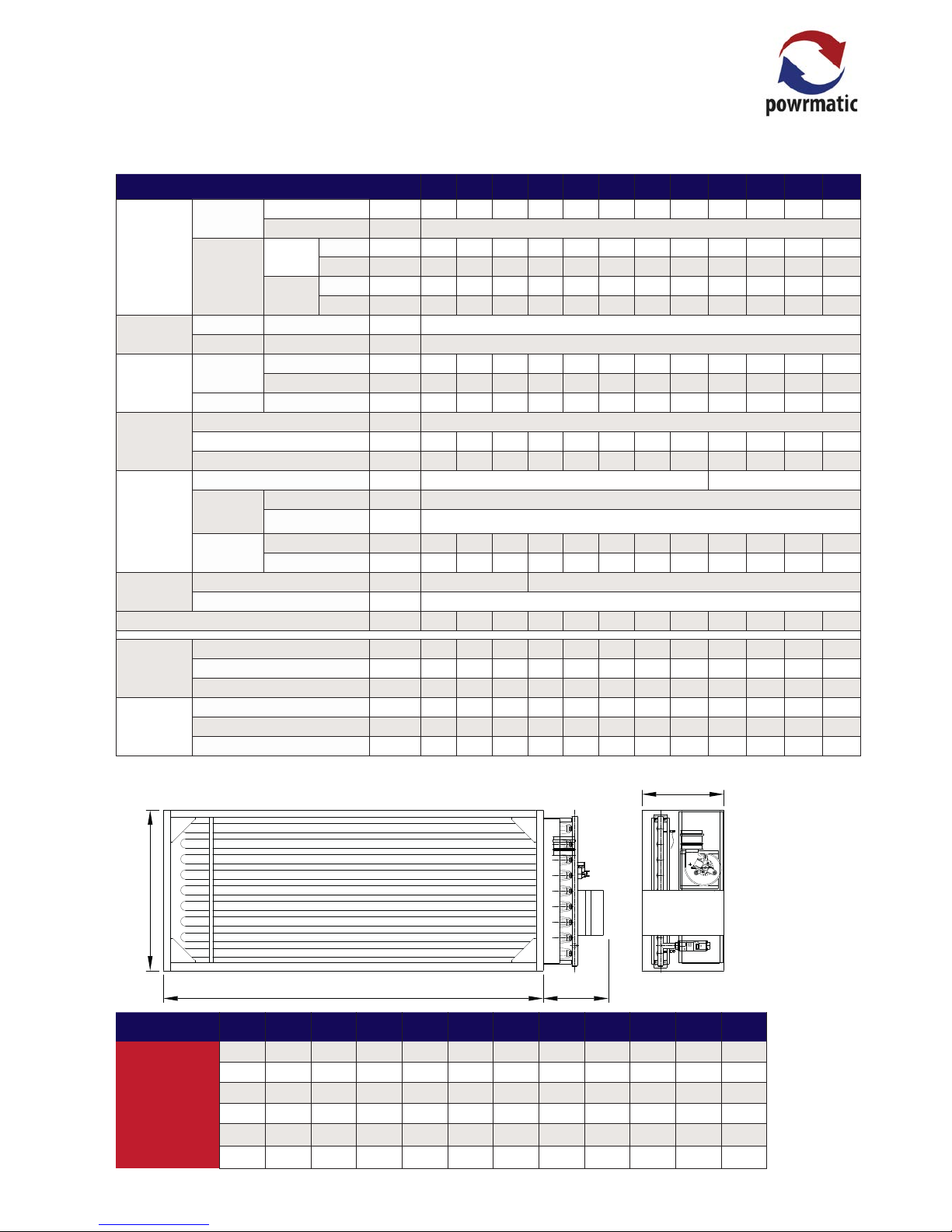
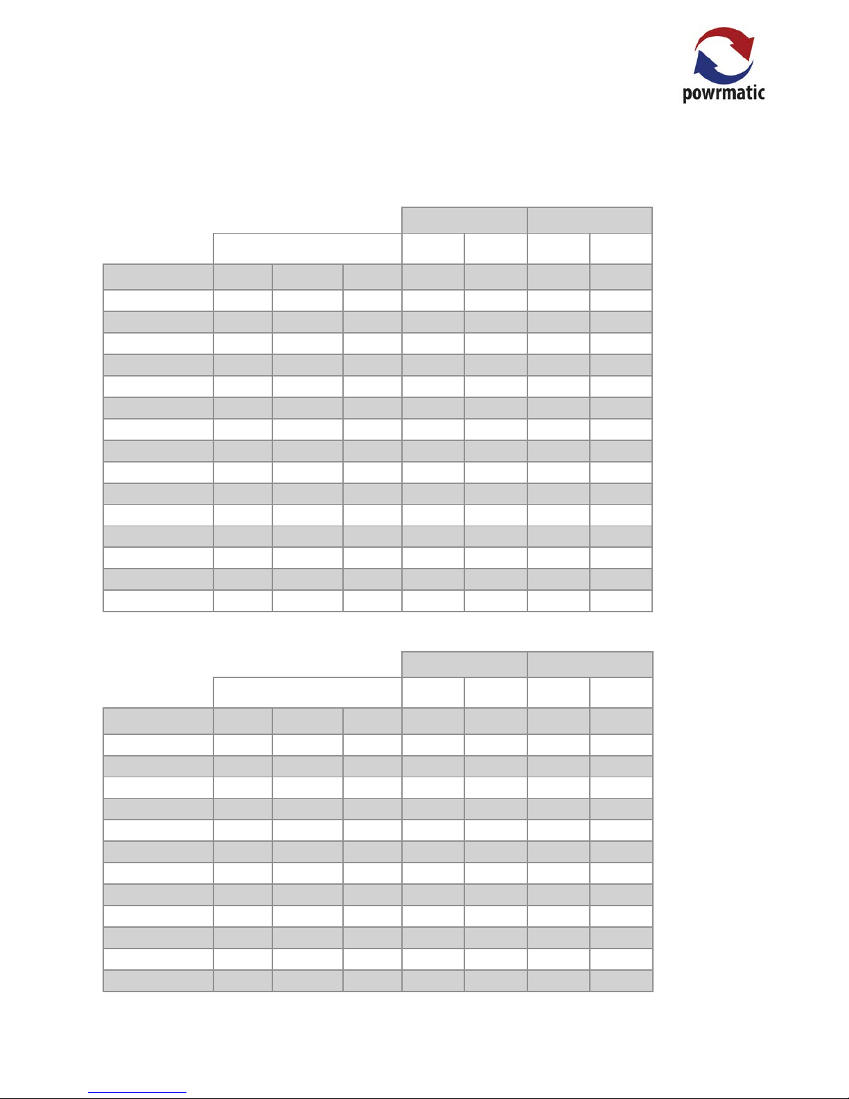
Duties & Dimensions
HEM-NVx Unit Dimensions
Model 10-3 15-4 18-5 25-5 30-6 40-8 50-6 60-7 75-9 100-12 110-13 125-15 150-18 175-21 200-24
Dimension
A
550
550 550 680 680 680 1050 1050 1050 1050 1050 1050 1050 1050 1050
B
305
458 458 531 531 741 531 601 741 950 1132 1272 1482 1690 1900
C
590
590 590 648 648 648 800 800 800 800 930 930 930 930 930
D 400 400 380 400 380 380 400 400 400 400 500 500 500 500 550
Flue Diameter
80
80 80 100 100 100 100 130 130 130 130 130 130 130 130
HEM-NVx
Model HEM-NVx
10-3 15-4 18-5 25-5 30-6 40-8 50-6 60-7 75-9 100-12 110-13 125-15 150-18 175-21 200-24
Output
On/Off
Max kW 10.0 15.0 18.0 25.0 30.0 40.0 50.0 60.0 75.0 100.0 110.0 125.0 150.0 175.0 200.0
Min kW n/a
High/Low &
Modulating
N.G.
G20
Max kW 10.0 15.0 18.0 25.0 30.0 40.0 50.0 60.0 75.0 100.0 110.0 125.0 150.0 175.0 200.0
Min. kW 5.4 8.0 9.6 13.4 16.0 21.6 26.5 31.7 39.9 53.3 58.7 66.7 80.0 93.3 106.7
LPG
G31
Max KW 10.0 15.0 18.0 25.0 30.0 40.0 50.0 60.0 75.0 100.0 110.0 125.0 150.0 175.0 200.0
Min. kW 5.4 7.7 9.8 14.4 16.5 21.5 25.2 28.0 38.0 54.0 59.8 68.0 81.6 95.2 108.8
Temp
Rise Max Δt °C 35
Air Off Max °C 70
Airflow
Min.
Volume
Natural Gas m
3
/s 0.34 0.44 0.58 0.71 0.86 1.01 1.55 1.90 2.22 2.78 2.99 3.39 4.14 4.67 5.31
LPG m
3
/s 0.33 0.35 0.50 0.83 0.69 0.99 1.19 1.90 1.73 2.50 2.64 2.99 3.67 4.17 4.75
Pressure
Drop
At above
Airflow
Pa 43 26 45 32 47 31 59 67 59 54 43 43 47 45 46
Electrics
V/ph/Hz 230/1/50 @ 0.3A
Current A/pha 0.304
Power Total kW 0.07
Fuel
Connection BSP/Rc ¾ 1¼
Minimum
Inlet
Pressure
Natural Gas mbar 20.0
LPG mbar 37.0
Rate
Natural Gas m
3
/h 1.16 1.74 2.09 2.91 3.49 4.65 5.87 7.05 8.91 11.75 12.79 14.45 17.69 20.33 23.60
LPG m
3
/h 0.44 0.65 0.78 1.09 1.31 1.74 2.18 2.61 3.26 4.35 4.79 5.44 6.53 7.61 8.70
Flue
Diameter mm ø 80 100 130
Max Length m 12
Nett Weight (single units) kg 38 45 53 60 68 74 91 114 123 140 145 168 195
230 270
Two
Modules
in Series
Δt = 70°C
Heat Output kW 20 30 36 50 60 80 100 120 150 200 220 250 300 350 400
Minimum Airflow
@ 0°C air inlet
m
3
/s 0.34 0.44 0.58 0.71 0.86 1.01 1.55 1.90 2.22 2.78 2.99 3.39 4.14 4.67 5.31
Pressure Drop At
Minimum Airflow
Pa 87 52 91 65 95 62 117 134 119 108 86 86 93 91 92
Page 7
page no. 7 of 48
HEMNVx & HEMSL Range Users, Installation & Servicing Instructions Doc Ref M103 issue 3.1 Feb 2018.
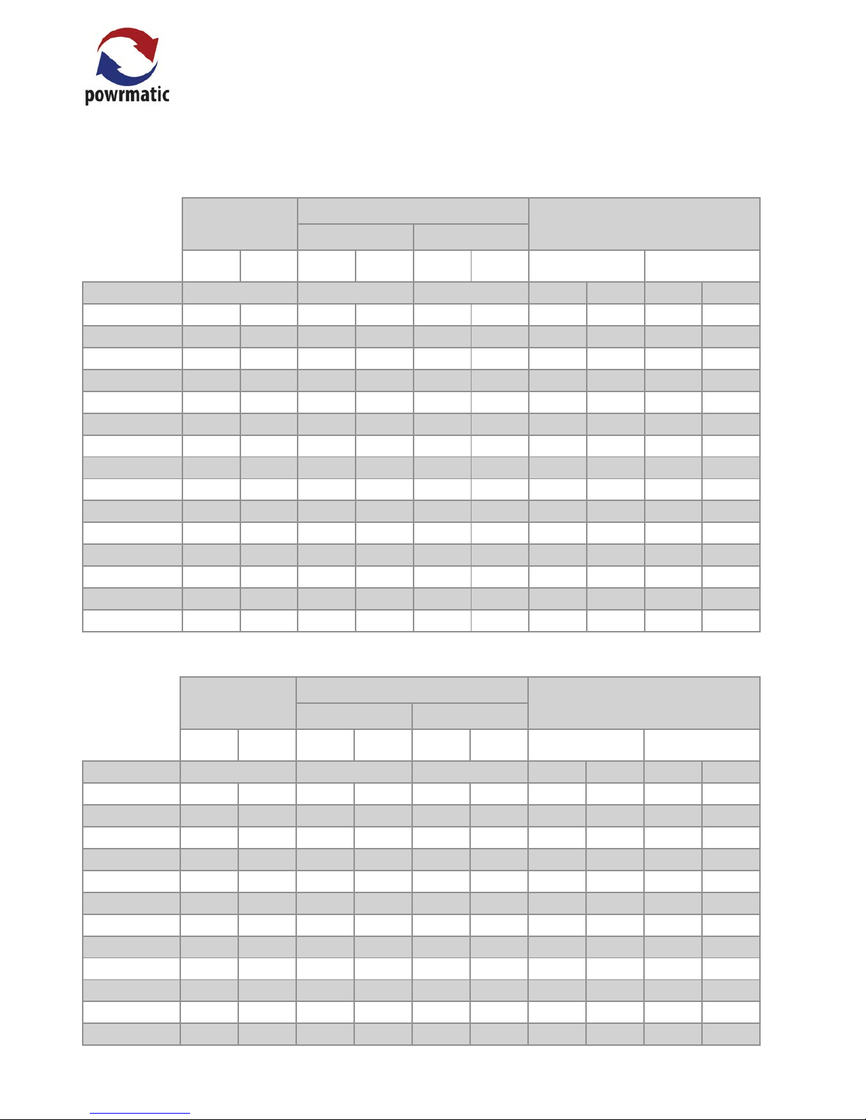
C
B
A D
HEM-SL Unit Dimensions
Model 30-6 45-9 50-6 60-12 75-9 75-15 90-18 100-12 125-15 150-18 175-21 200-24
Dimension
A
1250
1250 1850 1250 1850 1250 1250 1850 1850 1850 1850 1850
B
531
741 531 950 741 1272 1482 950 1272 1482 1690 1900
C
400
400 400 400 400 400 400 400 400 400 400 530
D
450 450 450 450 450 450 450 450
500 500 500 550
Flue Diameter
100
100 100 130 130 130 130 130 130 130 130 130
HEM-SL
Model - HEM-SL
30-6 45-9 50-6 60-12 75-9 75-15 90-18 100-12 125-15 150-18 175-21 200-24
Output
On/Off
Max kW 30.0 45.0 50.0 60.0 75.0 75.0 90.0 100.0 125.0 150.0 175.0 200.0
Min kW n/a
High/Low
Modulating
Nat Gas
G20
Max kW 30.0 45.0 50.0 60.0 75.0 75.0 90.0 100.0 125.0 150.0 175.0 200.0
Min kW 16.7 26.1 26.6 28.2 46.1 46.1 55.7 57.9 72.4 88.8 102.5 117.1
LPG
G31
Max KW 30.0 45.0 50.0 60.0 75.0 75.0 90.0 100.0 125.0 150.0 175.0 200.0
Min kW 16.6 24.5 25.3 28.3 38.1 38.1 54.4 54.5 68.2 83.7 96.5 110.3
Temp
Rise Max Δt °C 25
Air Off Max °C 70
Airflow
Minimum
Volume
Nat Gas m
3
/s 0.97 1.45 1.61 1.94 2.68 2.68 2.90 3.23 4.03 4.84 5.64 6.45
LPG m
3
/s 0.97 1.45 1.61 1.94 2.42 2.42 2.90 3.23 4.03 4.84 5.64 6.45
Pressure Drop At above airflow Pa 16 17 20 18 21 15 19 22 19 19 20 21
Electrics
V/ph/Hz 230/1/50@ 0.3A
Current A/pha 0.304 0.304 0.304 0.304 0.304 0.304 0.304 0.304 0.90 0.90 0.90 3.5
Power Total kW 0.07 0.07 0.07 0.07 0.07 0.07 0.07 0.07 0.207 0.207 0.207 0.80
Gas
Connection BSP/Rc ¾ 1¼
Minimum
Inlet
Pressure
Nat Gas mbar 20
LPG mbar 37.0
Rate
Nat Gas m
3
/h 3.53 5.29 5.88 7.05 8.82 8.82 10.58 11.76 14.7 18.04 20.81 23.78
LPG m
3
/h 1.36 2.04 2.27 2.73 3.41 3.41 4.09 4.54 5.68 6.97 8.07 9.19
Flue
Diameter mm ø 100 130
Maximum Length m 18
Nett Weight (single units) Kg 59 85 79 118 106 139 165 130 185 204 235 265
Two Modules
in Series
Max Δt = 50°C
Heat Output kW 60 90 100 120 150 150 180 200 250
300 350 400
Minimum Airflow @ 0°C air inlet m
3
/s 0.97 1.45 1.61 1.94 2.42 2.42 2.90 3.23 4.03 4.84 5.64 6.45
Pressure Drop At Above Airflow Pa 27 29 33 30 35 35 30 37 31 32 34 35
Three Modules
in Series
Max Δt = 75°C
Heat Output kW 90 135 150 180 225 225 270 300 375 450 525 600
Minimum Airflow @ 0°C air inlet m3/s 1.04 1.56 1.73 2.08 2.59 2.59 3.11 3.46 4.32 5.18 6.05 6.91
Pressure Drop At Above Airflow Pa 46 49 54 50 59 43 52 63 52 54 57 58
Page 8
page no. 8 of 48
HEMNVx & HEMSL Range Users, Installation & Servicing Instructions Doc Ref M103 issue 3.1 Feb 2018.
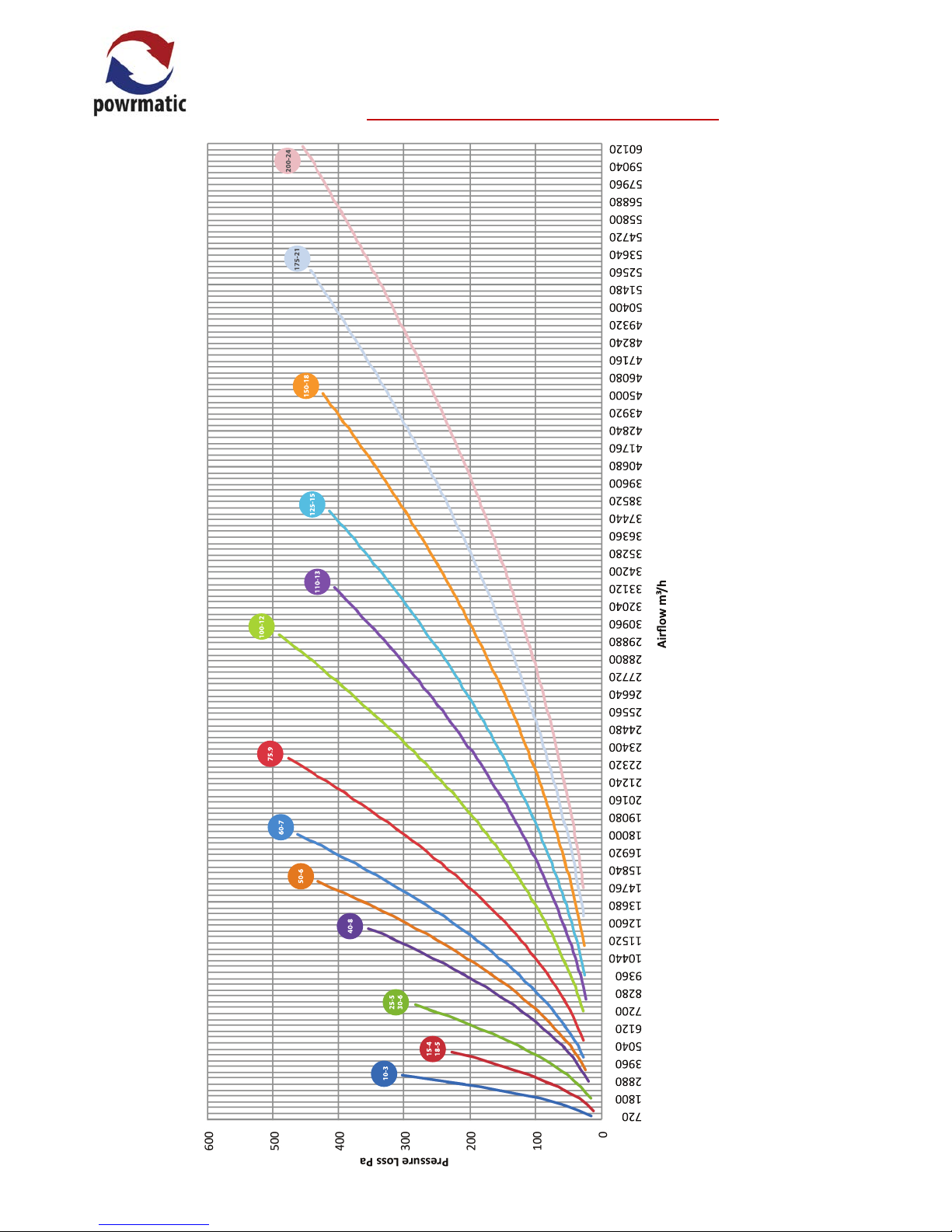
HEM-NVx Pressure Drop Graph
Note:
HEM NVx
The above data refers to a single module pressure drop. For twin models, refer to manufacturer.
10-3
720
1800
2880
3960
5040
6120
7200
7200
8280
9360
10440
11520
12600
13680
14760
14760
15840
16920
18000
19080
20160
21240
22320
22320
23400
24480
25560
26640
27720
28800
29880
29880
30960
32040
33120
34200
35280
36360
37440
37440
38520
39600
40680
41760
42840
43920
45000
45000
46080
47160
48240
49320
50400
51480
52560
52560
53640
54720
55800
56880
57960
59040
60120
60120
Airflow m³/h
15-4
18-5
25-5
30-6
40-8
50-6
60-7
75.9
100-12
110-13
125-15
150-18
175-21
200-24
Page 9
page no. 9 of 48
HEMNVx & HEMSL Range Users, Installation & Servicing Instructions Doc Ref M103 issue 3.1 Feb 2018.
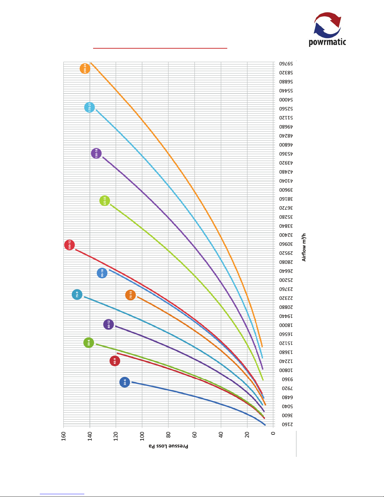
HEM-SL Pressure Drop Graph
30-6
45-9
50-6
60-12
75-9
75-15
90-18
100-12
125-15
2160
3600
5040
6480
7920
9360
10800
10800
12240
13680
15120
16560
18000
19440
20880
20880
22320
23760
25200
26640
28080
29520
30960
30960
32400
33840
35280
36720
38160
39600
41040
41040
42480
43920
45360
46800
48240
49680
51120
51120
52560
54000
55440
56880
58320
59760
Airflow m³/h
150-18
175-21
200-24
Note:
HEM-SL
The above data refers to a single module pressure drop. For twin & triple models, refer to manufacturer.
Page 10
page no. 10 of 48
HEMNVx & HEMSL Range Users, Installation & Servicing Instructions Doc Ref M103 issue 3.1 Feb 2018.
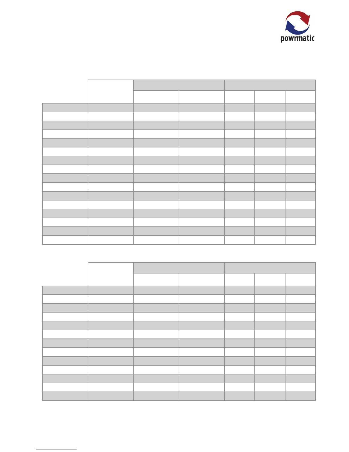
(Max) (Min)
Injectors
Burner
Pressure
Gas Rate
(nominal)
Burner
Pressure
Gas Rate
(nominal)
MODEL No. Size (mm)
Marked mbar m³/ h mbar m³/h
HEMNVx 10-3 3 1.67 380 10.7 1.16 3.2 0.63
HEMNVx 15-4 4 1.67 380 13. 6 1.74 4.1 0.95
HEMNVx 18-5 5 1.67 380 10.7 2.09 3.2 1.15
HEMNVx 25-5 5 1.94 500 13. 3 2.91 4.0 1.60
HEMNVx 30-6 6 1.94 500 13.6 3.49 4.1 1.92
HEMNVx 40-8 8 1.94 500 13.2 4.65 4.0 2.56
HEMNVx 50-6 6 2.54 750 12.6 5.87 3.8 3.19
HEMNVx 60-7 7 2.54 750 12 . 8 7.05 3.9 3.84
HEMNVx 75-9 9 2.54 750 12. 5 8.91 3.8 4.79
HEMNVx 100-12 12 2.54 750 12.7 11. 75 3.8 6.39
HEMNVx 110-13 7+6 2.54 750 12.9 12.79 3.9 7. 03
HEMNVx 125-15 9+6 2.54 750 12. 5 14.45 3.8 7.9 9
HEMNVx 150-18 9+9 2.54 750 12. 5 17.69 3.8 9.59
HEMNVx 175-21 12+9 2.54 750 12. 5 20.33 3.8 11.19
HEMNVx 200-24
12+12 2.54 750 12.5 23.60 3.8 12.78
Injector Sizes & Burner Pressures - Natural Gas - Group H - G20 Net CV (Hi = 34.02MJ/m³
Minimum Inlet Pressure = 20.0mbar
Maximum Inlet Pressure = 60mbar
(Max) (Min)
Injectors
Burner
Pressure
Gas Rate
(nominal)
Burner
Pressure
Gas Rate
(nominal)
MODEL No. Size (mm)
Marked mbar m³/h mbar m³/h
HEMSL 30-6 6 1.94 500 13.8 3.53 4.4 1.99
HEMSL 45-9 9 1.94 500 13.4 5.29 4.6 3.16
HEMSL 50-6 6 2.54 750 12 . 3 5.88 3.7 3.20
HEMSL 60 -12 12 1.94 500 13.6 7. 0 5 3.2 3.40
HEMSL 75-9 9 2.54 750 12. 5 8.82 4.9 5.54
HEMSL 75-15 15 1.94 500 13.6 8.82 5.4 5.54
HEMSL 90-18 18 1.94 500 13.7 10.58 5.2 6.51
HEMSL 100-12 12 2.54 750 12.7 11.76 4.3 6.86
HEMSL 125 -15 15 2.54 750 12.3 14.70 4.2 8.58
HEMSL 150-18 18 2.54 750 13.4 18.04 4.6 10.53
HEMSL 175-21 21 2.54 750 12.6 20.81 4.3 12 .14
HEMSL 200-24 24 2.54 750 13. 3 23.78 4.5 13. 88
HEM-SL
HEM-NVx
1.2 Technical Data
Page 11
page no. 11 of 48
HEMNVx & HEMSL Range Users, Installation & Servicing Instructions Doc Ref M103 issue 3.1 Feb 2018.
Injector Sizes & Burner Pressures - Propane G31 Net CV (Hi = 88.00MJ/m³
(Max) (Min)
Injectors
Burner
Pressure
Gas Rate
Burner
Pressure
Gas Rate
MODEL No. Size (mm)
Marked mbar m³/ h mbar m³/h
HEMNVx 10-3 3 1.1 tba 23.9 0.45 9.0 0.28
HEMNVx 15-4 4 1.15 tba 25.3 0.67 7.9 0.38
HEMNVx 18-5 5 1.15 tba 23.3 0.81 8.8 0.49
HEMNVx 25-5 5 1. 36 240 23.0 1.12 10.0 0.74
HEMNVx 30-6 6 1.36 240 22.9 1. 35 8.6 0.83
HEMNVx 40-8 8 1.36 240 22.9 1.80 8.4 1.09
HEMNVx 50-6 6 1.75 500 23.2 2.25 7. 5 1.28
HEMNVx 60-7 7 1.75 500 24.5 2.70 8.2 1.47
HEMNVx 75-9 9 1.75 500 23.2 3.37 8.5 1.92
HEMNVx 100-12 12 1.75 500 23.2 4.50 8.7 2.76
HEMNVx 110-13 7+6 1.75 500 23.9 4.95 9.0 3.03
HEMNVx 125-15 9+6 1.75 500 23.2 5.62 8.7 3.45
HEMNVx 150-18 9+9 1.75 500 23.2 6.74 8.7 4.14
HEMNVx 175-21 12+9 1.75 500 23.2 7.87 8.7 4.82
HEMNVx 200-24 12+12 1.75 500 23.2
8.99 8.7 5.51
(Max) (Min)
Injectors
Burner
Pressure
Gas Rate
Burner
Pressure
Gas Rate
MODEL No. Size (mm)
Marked mbar m³/h mbar m³/h
HEMSL 30-6 6 1.36 240 20.5 1.36 6.5 0.76
HEMSL 45-9 9 1.36 240 20.4 2.04 6.4 1.15
HEMSL 50-6 6 1.94 500 14.6 2.27 3.9 1.18
HEMSL 60 -12 12 1.36 240 19.5 2.73 4.9 1.36
HEMSL 75-9 9 1.94 500 14.8 3.41 4.0 1.77
HEMSL 75-15 6+9 1.36 240 20.2 3.41 5.5 1.77
HEMSL 90-18 9+9 1.36 240 20.5 4.09 7. 4 2.45
HEMSL 100-12 12 1.94 500 14. 8 4.54 4.6 2.54
HEMSL 125 -15 6+9 1.94 500 14.6 5.68 4.6 3.18
HEMSL 150-18 9+9 1.94 500 16.0 6.97 5.0 3.90
HEMSL 175-21 9+12 1.94 500 15.2 8.07 4.8 4.50
HEMSL 200-24 12+12 1.94 500 15.0 9.19 4.7 5.14
Minimum Inlet Pressure = 37mbar
Maximum Inlet Pressure = 60mbar
HEM-SL
HEM-NVx
Page 12
page no. 12 of 48
HEMNVx & HEMSL Range Users, Installation & Servicing Instructions Doc Ref M103 issue 3.1 Feb 2018.
High Fire
Low Fire
Min Air Flow
Natural Gas LPG
Input
(Nett)
Output
Input
(Nett)
Output
Input
(Nett)
Output Natural Gas LPG
MODEL
kW kW kW m³/s m³/h m ³/s m³/h
HEMSL 30-6 33.3 30 18.8 16.7 18.7 16.6 0.97 3492 0.97 3492
HEMSL 45-9 50.0 45 29.2 26.1 28.0 24.5 1.45 5220 1.45 5220
HEMSL 50-6 55.6 50 30.3 26.6 28.9 25.3 1.61 5796 1.61 5796
HEMSL 60 -12 66.7 60 32.2 28.2 33.3 28.3 1.94 6984 1.94 6984
HEMSL 75-9 83.3 75 52.4 46.1 43.3 38.1 2.68 9648 2.42 8712
HEMSL 75-15 83.3 75 52.4 4 6.1 43.3 38.1 2.68 9648 2.42 8712
HEMSL 90-18 100.0 90 61.6 55.7 60.0 54.4 2.90 10440 2.90 10440
HEMSL 100-12 111.1 100 64.9 57.9 62.2 54.5 3.23 11628 3.23 11628
HEMSL 125 -15 138.9 125 81.1 72.4 7 7.8 68.2 4.03 14508 4.03 14508
HEMSL 150-18 170 . 5 150 99.6 88.8 95.5 83.7 4.84 17424 4.84 17424
HEMSL 175-21 196.6 175 114. 8 102.5 110 .1 96.5 5.64 20304 5.64 20304
HEMSL 200-24 224.7 200 131. 3 117.1 125.8 110. 3 6.45 23220 6.45 23220
High Fire
Low Fire
Min Air Flow
Natural Gas LPG
Input
(Nett)
Output
Input
(Nett)
Output
Input
(Nett)
Output Natural Gas LPG
MODEL
kW kW kW m³/s m³/h m³/s m³/h
HEMNVx 10-3 11. 0 10 6.0 5.4 6.8 5.4 0.34 1224 0.33 118 8
HEMNVx 15-4 16.5 15 9.0 8.0 9.2 7.7 0.44 1584 0.35 1260
HEMNVx 18-5 19. 8 18 10.9 9.6 12.1 9.8 0.58 2088 0.50 1800
HEMNVx 25-5 2 7. 5 25 15.1 13.4 18.03 14.4 0.71 2556 0.83 2988
HEMNVx 30-6 33.0 30 18.1 16.0 20.2 16.5 0.86 3096 0.69 2484
HEMNVx 40-8 44.0 40 24.2 21.6 26.6 21.5 1.01 3636 0.99 2564
HEMNVx 50-6 55.0 50 30.2 26.5 31.3 25.2 1.55 5580 1.19 4284
HEMNVx 60-7 65.9 60 36.3 31.7 35.9 28.0 1.90 6840 1.90 6840
HEMNVx 75-9 82.4 75 45.3 39.9 47.0 38.0 2.22 7992 1.73 6228
HEMNVx 100-12 109.9 100 60.4 53.3 67.5 54.0 2.78 10008 2.50 9000
HEMNVx 110-13 120.9 110 66.5 58.7 74.2 59.8 2.99 10764 2.64 9504
HEMNVx 125-15 137. 4 125 75.6 66.7 84.3 68.0 3.39 12204 2.99 10764
HEMNVx 150-18 164.8 150 90.7 80.0 101.2 81.6 4.14 14904 3.67 13212
HEMNVx 175-21 192. 3 175 105.8 93.3 118 .1 95.2 4.67 16812 4.17 15012
HEMNVx 200-24 219.8 200 120.9 106.7 134.9 108.8 5.32 19152 4.75 1710 0
Heater Specications
HEM-SL
HEM-NVx
Page 13
page no. 13 of 48
HEMNVx & HEMSL Range Users, Installation & Servicing Instructions Doc Ref M103 issue 3.1 Feb 2018.
Heater Specications cont
Power
Conpumption
Nominal CO Values Weights
Nat Gas (G20)
(High Fire)
Propane (G31)
(High Fire)
Module
only
Packaging Total
MODEL
VA % % kg kg kg
HEMNVx 10-3 140.4 6.0 6.2 38 12 50
HEMNVx 15-4 140.4 6.5 6.6 45 12 57
HEMNVx 18-5 14 0.4 6.3 7. 3 53 15 68
HEMNVx 25-5 140.4 7. 2 7. 4 60 15 75
HEMNVx 30-6 140.4 7.9 7.9 68 15 83
HEMNVx 40-8 140.4 7.5 7.8 74 15 89
HEMNVx 50-6 140.4 7.6 8.6 91 18 99
HEMNVx 60-7 121.1 8.2 9.0 114 18 132
HEMNVx 75-9 121.1 7.0 8.0 123 18 141
HEMNVx 100-12 164.4 7.0 8.3 140 21 161
HEMNVx 110-13 164.4 7.9 9.6 145 21 166
HEMNVx 125-15 314.4 8.3 8.5 168 25 193
HEMNVx 150-18 314.4 8.4 9.6 195 30 225
HEMNVx 175-21 314.4 8.6 9.7 230 32 262
HEMNVx 200-24 540.4 8.2 8.2 270 35 305
HEM-NVx
Power
Conpumption
Nominal CO Values Weights
Nat Gas (G20)
(High Fire)
Propane (G31)
(High Fire)
Module
only
Packaging Tot al
MODEL
VA % % kg kg kg
HEMSL 30-6 140.4 8.2 8.4 58.5 15 73.5
HEMSL 45-9 140.4 8.4 8.5 85 15 100
HEMSL 50-6 140. 5 8.5 8.6 79 18 97
HEMSL 60 -12 121.2 8.1 8.6 118 15 133
HEMSL 75-9 121.2 7.0 7.8 105. 5 18 123. 5
HEMSL 75-15 170.4 8.3 9.1 139 18 157
HEMSL 90-18 170.4 8.2 9.0 165 18 183
HEMSL 100-12 16 4.4 8 .1 8.8 130 21 151
HEMSL 125 -15 314.4 8.0 9.0 184.5 25 209.5
HEMSL 150-18 314.4 7. 7 9.1 206.5 30 236.5
HEMSL 175-21 314.4 8 .1 10.0 234.5 32 266.5
HEMSL 200-24 520.4 7. 2 7. 5 265 35 300
HEM-SL
Page 14
page no. 14 of 48
HEMNVx & HEMSL Range Users, Installation & Servicing Instructions Doc Ref M103 issue 3.1 Feb 2018.
1.3.1. Related Documents
The installation of the module(s) must be in accordance
with the rules in force and the relevant requirements of the
Gas Safety Regulations, Building Regulations and the I.E.E.
Regulations for Electrical Installations. It should also be in
accordance with any relevant requirements of the local gas
region, local authority and re authority and the relevant
recommendations of the following documents.
Institution of Gas Engineers & Managers
IGE/UP/1 (Ed.2) Strength and tightness testing and
purging of industrial and commercial gas installations.
IGE/UP/1A Soundness testing and direct purging of small
low pressure industrial and commercial gas installations.
IGE/UP/2 Gas installation pipe work, boosters and
compressors on industrial and commercial premises.
IGE/UP/10 (with Amendments October 2010) Installation
gas appliances in industrial and commercial premises.
British Standards Code of Practice
BS 5588 Fire precautions in the design and construction of
buildings.
Part 2 : 1985 Code of Practice for Shops
Part 3 : 1983 Code of Practice for Oce Buildings
BS 6230 Installation of Gas Fired Forced Convection Air
Heaters for Commercial and Industrial Space Heating.
Those appliances having a gross input rating not exceeding
60kW and installed to take their combustion air from
within the building must be installed in accordance with
the relevant recommendations of the following document.
BS 5440 Flues and Air Supply for gas appliances of rated
input not exceeding 60kW (1st and 2nd family gases), Part
2 – Air Supply
BS 5864 Code of Practice for installation of gas-red
ducted-air heaters of rated input not exceeding 60kW.
Electromagnetic Compatibility (EMC)
These heaters pass the following standards for
Electromagnetic Compatibility: EN 61000-6-3:2007 A1
(Generic Emissions for Residential, Commercial and Light
Industrial Environments) and EN 61000-6-2:2005 (Generic
Immunity for Industrial Environments).
1.3.2 Electrical Supply
Wiring external to the air heater must be installed in
accordance with the I.E.E. Regulations for Electrical
Installations and any local regulations which apply.
All modules are supplied by 230V - 1ph, 50Hz. The method
of connection to the main electricity supply must:-
- facilitate the complete electrical isolation of the unit(s)
- be in a readily accessible position adjacent to the unit(s)
- serve only the unit(s)
- have a contact separation of at least 3mm in all poles.
See the accompanying wiring diagram for the heater
electrical connections
1.3.3 Gas Supply
A servicing valve and union to facilitate servicing must
be tted to the gas inlet pipe work of the heater. The gas
supply must be completed in solid pipe work and be
adequately supported.
Warning
When completing the nal gas connection
to the heater do not place undue strain on
the gas pipe work of the heater.
1.3.3.1 Service Pipes
The local gas undertaking should be consulted at the
installation planning stage in order to establish the
availability of an adequate supply of gas. An existing
service pipe must not be used without prior consultation
with the local gas undertaking. The inlet gas pressure
under running conditions must not be less than 20.0mb.
1.3.3.2 Meters
An existing meter should be checked, preferably by the gas
undertaking, to ensure that the meter is adequate to deal
with the total rate of gas supply required by all connected
equipment.
1.3.3.3. Installation Pipes
Installation pipes should be tted in accordance with IGE/
UP/2. Pipe work from the meter to the air heater must be
of adequate size. Do not use pipes of a smaller size than
the inlet gas connection of the heater. The complete
installation must be tested for soundness as described in
the above Code.
1.3 General Requirements
Page 15

page no. 15 of 48
HEMNVx & HEMSL Range Users, Installation & Servicing Instructions Doc Ref M103 issue 3.1 Feb 2018.
1.3.4 Ventilation Requirements for AHU's
Refer to tables detailed on next page for calculated free
areas of ventilation grilles.
Refer to Index 1 for Air inlet/exhaust ue and ventilation
sketches
1.3.4.1 Type B ued installations.
Where AHU's are installed within the heated space (ie
not in a plant room) and having a building design air
change rate of greater than 0.5/h, additional provision for
ventilation is not required.
If the building design air change rate is less than 0.5/h,
additional provision for natural or mechanical ventilation
is required.
These being:
Natural Ventilation: Grilles having a free area of at least
2cm² per kW of rated heat input shall be provided at low
level i.e. below the level of the heater ue connection.
or
Mechanical Ventilation: Must ensure that the space air
change rate is at least 0.5/h, must be of the ‘input’ type and
interlocked to ensure the heaters cannot work if the input
system is not working.
1.3.4.2 Type B ued installations.
Where AHU's are installed in a plant room (ie not within
the heated space)
having combustion air drawn directly
from the room and connected to a ue that evacuates the
products of combustion directly from the room additional
provision for natural or mechanical ventilation is required.
These being:
Natural Ventilation:
There must be permanent air vents communicating
directly with the outside air, at high level and at low level.
For Plant Rooms
Low level (inlet) 4cm²/kw of total rated net heat input
High level (outlet) 2cm²/kw of total rated net heat input
Mechanical Ventilation: The minimum ow rate of
ventilation shall be 4.14m³/h per kilowatt of total rated heat
input.
1.3.4.3 Type C ued installations.
Where AHU's are Installed within the heated space (ie
not in a plant room)
having combustion air ducted to the
appliance and combustion products ducted to the outside
air, NO additional provision for the supply of either
combustion air or for combustion products dilution or
additional provision for the supply of air is necessary.
1.3.4.4 Type C ued installations.
Where AHU's are installed in a plant room (ie not within
the heated space)
having combustion air ducted to the
appliance and combustion products ducted to the outside,
air vents shall be provided and be permanently open.
To room or internal space
Low level (inlet) 10cm²/kw of total rated net heat input
High level (outlet) 10cm²/kw of total rated net heat input
Direct to outside air
Low level (inlet) 5cm²/kw of total rated net heat input
High level (outlet) 5cm²/kw of total rated net heat input.
1.3.5 Burner/Controls Enclosure
Where the ue system is a Type C12 or C32 the burner and
controls enclosure, whether it is part of the unit the module
is tted in or an enclosure in its own right, must meet the
requirement of BS EN1020 Clause 6.1.1.24 i.e. the air leakage
rate from the enclosure shall not exceed 0.5m³/h per kW of
heat input, with a maximum of 25 m³/h.
With the ue connected the terminal is sealed, any access
door is closed and the gas inlet is isolated. Air is passed
into the appliance via a ow meter and the air ow rate is
noted when the pressure inside the enclosure is steady at
0,5mbar above the atmospheric pressure.
NOTE A convenient method of testing the
appliance is to enclose the terminal in a plastic
bag into which an air entry pipe and tube
connected to a pressure gauge can be tted.
Page 16

page no. 16 of 48
HEMNVx & HEMSL Range Users, Installation & Servicing Instructions Doc Ref M103 issue 3.1 Feb 2018.
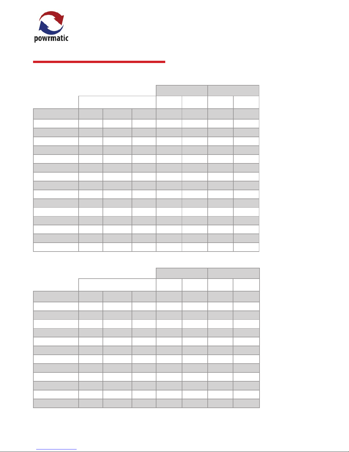
Type B22 Installation (these refer to section
2.2 of these instructions)
Air vents shall be permanently open.
In all cases gu res are per heater installe d.
For multi heater i nstallations the approp riate values for
each heater mus t be added together
Type C12 or C32 Installation (these refer to section 2.2 of
these instructions)
Air vents shall be permanently open.
Figures are fo r heaters in plant rooms or enc losures ONLY
In all cases gu res are per heater installe d.
For multi heater i nstallations the approp riate values for each heater mus t be
added together.
Input
kW
In the heated
space
In a plant room,
ventilation to outside
ventilation is to a room or
internal space
ventilation is to a outside air
Low level gril le.
Free area cm²
Low level gril le.
Free area cm²
High level g rille.
Free area cm²
Low level gril le.
Free area cm²
High level g rille.
Free area cm²
Low level gril le.
Free area cm²
High level g rille.
Free area cm²
HEMNVx 10 -3 10.99 22.0 44.0 22.0 109.9 109.9 55.0 55.0
HEMNVx 15-4 16.48 33.0 65.9 33.0 16 4.8 16 4.8 82.4 82.4
HEMNVx 18-5 19.78 39.6 79.1 39.6 19 7.8 19 7.8 98.9 98.9
HEMNVx 25-5 2 7.47 54.9 109.9 54.9 274.7 274.7 1374 1374
HEMNVx 30-6 32.97 65.9 131.9 65.9 329.7 329.7 164.9 16 4.9
HEMNVx 40-8 43.96 8 7.9 175. 8 87. 9 439.6 439.6 219.8 219.8
HEMNVx 50-6 54.94 109.9 219.8 109.9 549.4 549.4 274.7 274.7
HEMNVx 60-7 65.93 131.9 263.7 131.9 659.3 659.3 329.7 329.7
HEMNVx 75-9 82.42 164.8 329.7 164.8 824.2 824.2 412.1 412.1
HE MNVx 10 0-12 109.9 219.8 439.6 219.8 1098.9 1098.9 549.5 549.5
HEMNVx 110-13 120.9 241.8 483.5 241.8
120 8.8 120 8.8 604.4 604.4
HEMNVx 125-15 137. 4 274.7 549.4 274.7 1373. 6 1373. 6 686.8 686.8
HE MNVx 150-18 164. 8 329.7 659.4 329.7 1648.4 1648.4 824.2 824.2
HE MNVx 175-21 192. 3 384.6 769.2 384.6 1923.1 1923.1 961.6 961.6
HEMNVx 200-24 219.8 439.6 879.1 439.6 2197. 8 2197.8 1098.9 1098.9
HEM-NVx
Type B22 Installation (these refer to section
2.2 of these instructions)
Air vents shall be permanently open.
In all cases gu res are per heater installe d.
For multi heater i nstallations the approp riate values for
each heater mus t be added together
Type C12 or C32 Installation (these refer to section 2.2 of
these instructions)
Air vents shall be permanently open.
Figures are fo r heaters in plant rooms or enc losures ONLY
In all cases gu res are per heater installe d.
For multi heater i nstallations the approp riate values for each heater mus t be
added together.
Input
kW
In the heated
space
In a plant room,
ventilation to outside
ventilation is to a room or
internal space
ventilation is to a outside air
Low level gril le.
Free area cm²
Low level gril le.
Free area cm²
High level g rille.
Free area cm²
Low level gril le.
Free area cm²
High level g rille.
Free area cm²
Low level gril le.
Free area cm²
High level g rille.
Free area cm²
HEMSL 30-6 33.33 66.7 133.3 66.7 333.3 333.3 166.6 166.6
HEMSL 45-9 50.00 100.0 200.0 100.0 500.0 500.0 250.0 250.0
HEMSL 50-6 55.55 111.1 222.2 111.1 555.5 555.5 27 7.7 27 7.7
HE MSL 60-12 66.66 133.3 266.6 133. 3 666.6 666.6 333.3 333.3
HEMSL 75-9 83.33 166.7 333.3 166.7 833.3 833.3 416.7 416.7
HE MSL 75-15 83.33 166.7 333.3 166.7 833.3 833.3 416.7 416.7
HE MSL 90-18 100.00 200.0 400.0 200.0 1000.0 1000.0 500.0 500.0
HE MSL 100 -12 111.11 222.2 444.4 222.2 1111.1 1111.1 555.6 555.6
HEMSL 125-15 138 .88 27 7.7 555.5 27 7.7 1388 .8 1388.8 694.4 694.4
HE MSL 150-18 170 .45 340.9 681.8 340.9 1704.5 1704 .5 852.3 852.3
HE MSL 175-21 196.63 393.3 786.5 393.3
196 6.3 1966. 3 983.2 983.2
HEMSL 20 0-24 224.72 449.4 898.9 449.4 2247. 2 2 247. 2 112 3. 6 112 3. 6
HEM-SL
1.3.6 Ventilation Requirements
Page 17

page no. 17 of 48
HEMNVx & HEMSL Range Users, Installation & Servicing Instructions Doc Ref M103 issue 3.1 Feb 2018.
Before installation, check that the:
- local distribution conditions, nature of gas and pressure,
and the current state adjustment of the appliance are
compatible,
- local electrical supply conditions are compatible with the
electrical data given on the data plate.
2.1.1. Unpacking
The module has been red and tested at the factory prior
to despatch. Check the despatch documents and the data
plate axed to the module to conrm that it is as ordered
and compatible with the gas and electrical supplies on site.
Read the entire document before commencing installation.
2.1.2 Module Types
Modules are available for:
a) Use within an additional casing e.g. an air handling unit.
i.e no factory tted burner /controls housing.
b) Internal use with a burner /controls housing.
c) For external use with a weatherproof burner/controls
housing.
Type a) and type b) can be for either B22 (combustion air
taken from the internal space) or C12/C32 (combustion air
taken from outside) ue congurations.
2.1.3 Module Fitment
Modules must be handled safely and lifted using the tted
lifting brackets. These can be removed on installation if
necessary. The module should slide into the air handling
unit/duct section between top and bottom guide rails
sized to suit the module in question. It must be possible
to easily remove the module at a later date should this be
necessary.
There must be eective sealing between the module
burner/controls section so that there is no air leakage from
the main air ow path into the burner/controls section.
Modules may be orientated so that the burner manifold(s)
is vertical or horizontal.
For external units please note:
The lowest edge of air inlets must be at least
500 mm above ground level. Access panels
and doors to be removed during normal
servicing shall be designed so that repeated removal and
replacement does not damage the insulation or impair the
waterproong of the unit.
No opening (e.g. electrical wiring points) from the inside of
the appliance to the outside air shall permit the entry of a
16 mm diameter ball.
2.1.4 Combustion Air Inlet and Flue Products Outlet
Combustion air inlet(s) and ue outlets must be connected
to each HEM unit so when the unit is installed, their
termination is at least 500mm from ground level.
2.1.4.1 Type B Flued Installations
The combustion air inlet attachment requires an aperture
to be cut and four pilot holes to be drilled in the front plate
of the controls compartment to the following dimensions
and must be installed on a level plane.
220
96
12
12
40.5
40.5
4 HOLES Ø3
The combustion air inlet attachment can then be oered
up to the front plate and secured using self tapping screws
ensuring a positive seal to prevent any ingress of water.
Alternatively an air inlet orice having a free area of at
least 110 cm² (app 105 x 105mm) can be cut into the burner
enclosure panel to facilitate the combustion air.
Two air inlet attachments (or free area of 220cm²)
are required on models SL75-15; SL90-18; NVx &
SL125; NVx & SL50; NVx & SL175 and NVx & SL200
A ue outlet terminal is required with every module and
is connected to the exhaust fan. Flue outlet terminals can
be either standard 450mm long terminals or Powrmatic
approved ue system. Flue terminals may be extended by
the use of a Powrmatic approved ue piece with sealing
ring or cut down to suit the particular application ensuring
the ue terminal projects from the front plate by at least
75mm
min 75mm
2.1 Fitting the Unit
Page 18

page no. 18 of 48
HEMNVx & HEMSL Range Users, Installation & Servicing Instructions Doc Ref M103 issue 3.1 Feb 2018.
For horizontal type B ued installations a Combustion
Air Inlet and Flue Termination piece is supplied for each
module (two Combustion Air Inlets are supplied with
models HEMNVx 150, 175 & 200). For Vertical type B ued
installations a Combustion Air Inlet and Flue Termination
piece is supplied for each module (two Combustion Air
Inlets are supplied with models HEMNVx 150, 175 & 200).
Horizontal Flue Outlets, Type B Installation
Exhaust ue outlet positions are shown in the following diagrams and tables.
HEM NVx
HEM SL
Size A B C ØD
10-3 399 167 108 91
15-4 399 167 108 91
18-5 399 167 108 91
25-5 443 187 121.5 112
30-6 443 187 121.5 112
40-8 637 187 121.5 112
50-6 443 217 121.5 112
60 -7 501 227 145. 5 142
75-9 641 227 145. 5 142
100-12 848 226 151.5 142
110 -13 997 204 181 142
125 -15 1137 204 181 142
150-18 1347 204 181 142
175-21 1554 204 181 142
200-24 1759 153 181 142
A
B
HORIZONTAL FLUE POSITION
ØD HOLE FOR FLUE SEAL
C
A
B
HORIZONTAL FLUE POSITION
ØD HOLE FOR FLUE SEAL
C
HORIZONTAL FLUE POSITION
ØD HOLE FOR FLUE SEAL
A
BC
HORIZONTAL FLUE POSITION
ØD HOLE FOR FLUE SEAL
A
BC
Size A B C ØD
30-6 453.5 179 121.5 112
45-9 659 179 121.5 112
50-6 453.5 179 121.5 112
60-12 815 188 145.5 142
75-9 651 188 145.5 142
75-15 1172 188 145.5 142
90-18 1333 187 151.5 142
100-12 848 187 151.5 142
125 -15 1135 35 180. 5 142
150-18 1345 35 180.5 142
175-21 1552 35 180. 5 142
200-24 1769 116 181 142
The maximum permitted length of ue system is 18m. If an
oset is required a set of 45° bends should be used being
equivalent to 0.5m of ue length. 90° bends may be used
but each set will be equivalent to 1.0m of ue length.
Page 19

page no. 19 of 48
HEMNVx & HEMSL Range Users, Installation & Servicing Instructions Doc Ref M103 issue 3.1 Feb 2018.
HEMNVx HEMSL A CRS ØD
10-3 n/a 120 91
15-4 n/a 120 91
18-5 n/a 120 91
25-5 n/a 142 112
30-6 30-6 142 112
40-8 n/a 142 112
n/a 45-9 142 112
50-6 50-6 142 112
60 -7 n/a 220 142
n/a 60-12 220 142
75-9 75-9 220 142
A CRS
ØD
ØD
Silicone
Seals
Simulated enclosure
A CRS
2.1.4.2 Type C Flued Installations
For vertical type C ued installations a vertical concentric
ue system should be used.
Nominal ue diameters are either 80mm, 100mm or
130mm dependent on heater size (refer to duties section
on page 6)
The maximum permitted length of ue system is 9m, If
an oset is required two sets of 45° bends should be used
each set being equivalent to 0.5m of ue length. 90° bends
may be used but each set will be equivalent to 1.0m of ue
length.
Exhaust ue outlet positions are shown in the previous
diagrams and tables.
Air inlet holes should be cut to the dimensions in the
following table to accept the silicone seals supplied.
(where ØD is the actual cut size in the casing/sheet metal).
The silicone seals supplied are not water tight
and should not be used in external vertical
applications. A suitable water tight seal or
sealant must be used in these instances.
HEMNVx HEMSL A CRS ØD
n/a 75 -15 220 142
n/a 90 -18 220 142
100-12 100 -12 220 142
110 -13 n/a 220 142
125 -15 125-15 220 142
150-18 150 -18 220 142
175-21 175-21 220 142
200-24 200-24 220 142
Type C Flue and air inlet cut hole sizes
and centres distances.
(refer to table below)
Page 20

page no. 20 of 48
HEMNVx & HEMSL Range Users, Installation & Servicing Instructions Doc Ref M103 issue 3.1 Feb 2018.
2.1.5 Gas Installation
The whole of the gas installation, including the meter,
should be inspected and tested for soundness and purged
in accordance with the recommendations of IM/16:1988.
2.1.6 Electrical Connections
Only a suitably qualied operative can complete the
electrical installation and must observe the rules in force.
All electrical connections are made to the screw terminals
in the control section and should be in accordance with the
terminal markings and the wiring diagram for the module.
Module(s) must be earthed.
A lockout indicator light and reset button are tted in the
control panel. If required these functions can be duplicated
remotely from the module.
2.1.7 Main Air Fan
The module(s) does not include the main air moving fan.
Direction of airow may be either R-L or L-R for vertically
orientated modules or from top to bottom or bottom to
top for horizontally orientated units.
2.1.7.1 Main Fan Interlock
The main fan must be interlocked to the module by a
pressure switch or sail switch or equivalent so that if the
main air ow fails for any reason the module(s) is shut
down.
2.1.7.2 Minimum Airow Requirment
The minimum airows specied in section 1.2 must not be
reduced.
2.1.7.3 Maximum Airows
The airow across the module(s) should be kept at a level
that ensures condensation in the tubes will not occur with
the remainder of the air ow passing through a bypass
section to be mixed with the heated air downstream of the
module(s).
Please contact the Powrmatic oce to obtain the
appropriate bypass dimensions to suit the specic heater.
2.1.7.4 Main Fan Over-run
The main fan controls must ensure that when the module
is tuned o, i.e. the heat demand is satised, the main fan
continues to run for 3-4 minutes to dissipate the residual
heat from the module.
2.1.8 Flue System
Only ue systems supplied through Powrmatic Ltd may be
used with HEM modules. In all cases the ue outlet socket
must be connected via the provided ue system to outside
air.
The maximum permitted length of ue system is 9m, or
18m if the ue outlet only is used. If an oset is required two
sets of 45° bends should be used each set being equivalent
to 0.5m of ue length. 90° bends may be used but each set
will be equivalent to 1.0m of ue length.
All outer joints must be nished with the provided locking
bands. A smear of silicon grease to the inside of sockets will
assist in tting components together.
All ue and combustion air ducts must be supported
independently of the air heater.
The ue or ue/combustion air terminal must not be
installed so as to be less than:
300mm below an opening e.g. window, air brick etc.
200mm below eaves or gutter.
300mm from an internal or external corner.
1200mm from a surface facing the terminal.
1500mm vertically from another terminal on the same wall.
300mm horizontally from another terminal on the same
wall.
2000mm from ground level.
The ue must terminate in a freely exposed position and
be sited to prevent the products of combustion entering
any opening in a building in such concentration as to be
prejudicial to health or a nuisance.
Twin Wall Flue can also be used
2.1.9 Condensate Drainage
If, given the application and usage of the module, it is
considered that condensate will be formed at times then
the condensate drain pipe at the base of the unit must be
tted with an external trap, equivalent to that shown below,
the outlet of which must be run to a local drain point. The
trap can be a proprietary item or fabricated using standard
domestic 32mm waste water ttings in which case ensure
that the dimensions shown are adhered to.
The trap must be lled with water after installation and
before the heater is commissioned. The trap and associated
pipe work must be protected from freezing.If drainage
under gravity is not possible a condensate pump should be
used and installed following the manufacturers instructions.
Page 21

page no. 21 of 48
HEMNVx & HEMSL Range Users, Installation & Servicing Instructions Doc Ref M103 issue 3.1 Feb 2018.
Dual Burner Controls Compartment
2.2 General Identication of Items
Exhaust
Header Box
Upper
Burner Set
Lower
Burner Set
Exhaust Fan
Exhaust Fan Flow
Sensing Point
Gas Valves
Gas Inlet
Controls
Panel
Upper Spark
Ignition Probe
Probe
Limit
Thermostat
Sequence
Controllers
Exhaust Fan
APS
Incoming
Electrical
Connection
Point
Limit
Indicators
Lockout
Indicators
Fuses
Burner Set
(behind Heat Shield)
Exhaust Fan Exhaust
Header Box
Spark Ignition
Probe
Gas Valv
Inlet
Control
Panel
Exhaust Fan
Flow Sensing
Point
Incoming Electrical
Connection Point
Sequence
Controller
Exhaust Fan
APS
Limit
Thermostat
Limit
Indicator
Lockout
Indicator
Fuse
e
Gas
Single Burner Controls Compartment
Single Burner Internal Components
Dual Burner Internal Components
Page 22

page no. 22 of 48
HEMNVx & HEMSL Range Users, Installation & Servicing Instructions Doc Ref M103 issue 3.1 Feb 2018.
Electrical Connections
Warning: THIS APPLIANCE MUST BE
EARTHED.
Warning: Wiring external to the unit must
be carried out by an appropriately
qualied person to current IEE regulations
for Electrical Installations and any local regulations
which apply. Wiring should be completed in exible
conduit.
Heaters are for use with 230V, 1N, 50Hz supplies.
The method of connection to the main electricity supply
must:-
- facilitate the complete electrical isolation of the heater(s)
that will prevent remote activation of the heater during
servicing.
- be in a readily accessible position adjacent to the
heater(s).
- serve only the heater(s).
- have a contact separation of at least 3mm in all poles.
See section 2.4 or the accompanying wiring diagram for
the heater electrical connections.
Warning: Lockout reset is by a switched
Neutral to the controls in the heater.
Reference must be made to Section 1.2 to ascertain the
electrical loading of the unit(s) being installed so that
cables of adequate cross-sectional area are used for
the electrical installation. The length of the conductors
between the cord anchorage and the terminals must be
such that the current carrying conductors become taut
before the earth conductor if the cable or cord slips out
of the cord anchorage. All external controls must be of an
approved type.
2.3 Electrical Cable Installation
2.4 Wiring Terminal Locations
2.4.1 Single and Dual On/O and High-Low Burners
* where used
Heat LOW Demand
230V Input
Lockout 1 Indication
230V Output
Lockout 1 Reset
Neutral Input
Main fan
Proving Switch
(suppled by others)
*Heat HIGH Demand
230V Input
*Lockout 2 Indication
230V Output
*Lockout 2 Reset
Neutral Input
t1
t10
t8 t9
t3
t5 t6
t7
Page 23

page no. 23 of 48
HEMNVx & HEMSL Range Users, Installation & Servicing Instructions Doc Ref M103 issue 3.1 Feb 2018.
2.4.2 Single and Dual Modulating Burners
* where used
Modulating signal
0-10Vdc
Lockout 1 Indication
230V Output
Lockout 1 Reset
Neutral Input
Main fan
Proving Switch
(suppled by others)
Modulating
Ground 0V
*Lockout 2 Indication
230V Output
*Lockout 2 Reset
Neutral Input
t3
t10
t8 t9
t4
t5 t6
t7
Main fan Proving Switch
(suppled by others)
2.4.3 Proving Switch Enable Circuit
t10
t9
Page 24

page no. 24 of 48
HEMNVx & HEMSL Range Users, Installation & Servicing Instructions Doc Ref M103 issue 3.1 Feb 2018.
2.5 Wiring Diagrams
HEM Single Burner Unit (with ON/OFF Burner)
COM
NO
NC
L
LLL
E E
E
E
N N
N
N
1
1
5
5
6
6
11
11
12
12
15
15
16
16
C NO NC
23 1
LIVE
NEUTRAL
EARTH
B
r
0
.
5
Or 0.5
B
l
u
0
.
5
B
l
u
0
.
5
B
l
u
0
.
5
Yel 0.5
Wh 0.5
Br 0.5
B
r
0
.5
B
lu
0
.5
W
h
0
.
5
B
l
k
0
.
5
O
r
0
.5
B
lu
0
.
5
B
r
0
.5
B
r
0
.
5
Br 0.5
A
Yel 0.5
B
C
D
EF
G
H
I
B
lu
0
.
5
J K
L
M
COMPONENT LIST
Powrmatic part #
Model Specic
142403611
143100661
146522174
Model specic
Model specic
143000816
143000526
143070274
143100603
143100563
Model specic
142423003
Heat Demand 230V Input
Lockout 1 Indicator 230v Output
Lockout 1 Reset - Neutral Switch
A. Ignition Sequence Controller
B. GTLHR309 Limit Stat
C. Neon Indicator
D. Air Pressure Switch LGW3 A2
E. Main Gas Valve
F. Exhaust / Combustion Fan
G. 230v Relay
H. Fuse Holder 3.15A
I. Internal Lockout Reset Button
J. Hylec Terminal Block 3 Way
K. Terminal Block
L. Ignition Electrode
M. Rectication Probe
Br 0.5
Blu 0.5
Blu 0.5
Br 0.5
Blu 0.5
Br 0.5
Wiring Legend
NOTES
Connections made by Control board Assembler
Connections made by Final Assembler
Connections made by Installer
Br 0.5
Mains Input: 230v 50Hz 1ph Supply.
For input power refer to Installation instructions.
Warning: High voltages present at the ignition
electrode when the unit attemps to light.
External Controls
Connections
9
9
10
10
Main Fan Proving Pressure Switch
(Supplied by Others)
Blu 0.5
1
2
3
4
5
6
7
8
9
1
0
1
1
1
2
1
6
1
7
1
8
1
9
1
3
1
4
1
5
J
5
/ C
O
N
6
J
T
2
J
6
/
C
O
N
5
J
T
1
1
1
1
Gr/Yel 0.5
Page 25

page no. 25 of 48
HEMNVx & HEMSL Range Users, Installation & Servicing Instructions Doc Ref M103 issue 3.1 Feb 2018.
HEM Dual Burner Unit (with ON/OFF Burner)
COM
NO
NC
L
LLL
E
E E E
N
N N N
1
1
5
5
6
6
7
7
11
11
12
12
13
13
14
14
15
15
16
16
8
8
23 1
COM
NO
NC
COM
NO
NC
C NO NC
23 1
LIVE
NEUTRAL
EARTH
B
r
0
.
5
B
l
u
0
.
5
B
l
u
0
.5
B
l
u
0
.
5
B
r
0
.
5
B
lu
0
.5
B
lu
0
.5
W
h
0
.
5
B
l
k
0
.
5
B
lu
0
.5
B
r
0
.
5
B
r
0
.
5
Br 0.5
Wh 0.5
Yel 0.5
Yel 0.5
Wh 0.5
Br 0.5BB
l
l
u
u
0
0
.
.5
5
B
r
0
.5
B
lu
0
.5
W
h
0
.
5
B
l
k
0
.
5
O
r
0
.5
B
lu
0
.
5
B
r
0
.5
O
r
0
.5
B
r
0
.5
Br 0.5
Yel 0.5
Yel 0.5
A
Yel 0.5
A
B B
C
C
D
EEF
GG
G
HH
I
B
lu
0
.
5
I
J K
L
M
L
M
COMPONENT LIST
Powrmatic part #
Model Specic
142403611
143100661
146522174
Model specic
Model specic
143000816
143000526
143070274
143100603
143100563
Model specic
142423003
A. Ignition Sequence Controller
B. GTLHR309 Limit Stat
C. Neon Indicator
D. Air Pressure Switch LGW3 A2
E. Main Gas Valve
F. Exhaust / Combustion Fan
G. 230v Relay
H. Fuse Holder 3.15A
I. Internal Lockout Reset Button
J. Hylec Terminal Block 3 Way
K. Terminal Block
L. Ignition Electrode
M. Rectication Probe
Br 0.5
Blu 0.5
Blu 0.5
Br 0.5
Blu 0.5
Br 0.5
Wiring Legend
Heat Demand 230V Input
Lockout 1 Indicator 230v Output
Lockout 1 Reset - Neutral Switch
Lockout 2 Indicator 230v Output
Lockout 2 Reset - Neutral Switch
NOTES
Connections made by Control board Assembler
Connections made by Final Assembler
Connections made by Installer
Mains Input: 230v 50Hz 1ph Supply.
For input power refer to Installation instructions.
Warning: High voltages present at the ignition
electrode when the unit attemps to light.
Br 0.5
O
External Controls
Connections
10
10
9
9
Main Fan Proving Pressure Switch
(Supplied by Others)
B
B
l
l
u
u
0
0
.
.
5
5
1
2
3
4
5
6
7
8
9
1
0
1
1
1
2
1
6
1
7
1
8
1
9
1
3
1
4
1
5
J
5
/
C
O
N
6
J
T
2
J
T
1
J
6
/
C
O
N
5
1
1
1
1
2
3
4
5
6
7
8
9
1
0
1
1
1
2
1
6
1
7
1
8
1
9
1
3
1
4
1
5
J
5
/ C
O
N
6
J
T
2
J
T
1
J
6
/
C
O
N
5
1
1
1
Gr/Yel 0.5 Gr/Yel 0.5
COM
NO
NC
MASTER
SLAVE
CONTROLLER
CONTROLLER
Or 0.5
Blu 0.5
Br 0.5
Br 0.5
G
B
r
0
.5
Page 26

page no. 26 of 48
HEMNVx & HEMSL Range Users, Installation & Servicing Instructions Doc Ref M103 issue 3.1 Feb 2018.
HEM Single Burner Unit (with HIGH/LOW Burner)
COM
NO
NC
LLL
L
E
E E E
N N
N
N
1
1
3
3
5
5
6
6
11
11
12
12
15
15
16
16
C NO NC
23 1
LIVE
NEUTRAL
EARTH
B
r
0
.
5
Or 0.5
B
l
u
0
.
5
B
l
u
0
.
5
B
l
u
0
.
5
Yel 0.5
Wh 0.5
Br 0.5
B
r
0
.5
B
lu
0
.5
W
h
0
.
5
B
l
k
0
.
5
O
r
0
.5
B
lu
0
.
5
B
r
0
.5
B
r
0
.
5
Br 0.5
A
Yel 0.5
B
C
D
EF
G
H
I
B
lu
0
.
5
J
K
L
M
COMPONENT LIST Powrmatic part #
Q. Hi-Lo Gas Valve Head
Model Specic
142403611
143100661
146522174
Model specic
Model specic
143000816
143000526
143070274
143100603
143100563
Model specic
142423003
1 4 2466402
A. Ignition Sequence Controller
B. GTLHR309 Limit Stat
C. Neon Indicator
D. Air Pressure Switch LGW3 A2
E. Main Gas Valve
F. Exhaust / Combustion Fan
G. 230v Relay
H. Fuse Holder 3.15A
I. Internal Lockout Reset Button
J. Hylec Terminal Block 3 Way
K. Terminal Block
L. Ignition Electrode
M. Rectication Probe
N. O.P.
Heat Demand 230V Input
Heat Hi Demand 230V Input
Lockout 1 Indicator 230v Output
Lockout 1 Reset - Neutral Switch
Br 0.5
Blu 0.5
Blu 0.5
Br 0.5
Wiring Legend
NOTES
Connections made by Control board Assembler
Connections made by Final Assembler
Connections made by Installer
Q
Br 0.5
Mains Input: 230v 50Hz 1ph Supply.
For input power refer to Installation instructions.
Warning: High voltages present at the ignition
electrode when the unit attemps to light.
7
8
Note: When the valve
is de-energized the
heater operates in
low re.
External Controls
Connections
B
l
u
0
.5
Y
e
l
0
.
5
9
9
10
10
Main Fan Proving Pressure Switch
(Supplied by Others)
COM
NO
NC
G
Blu 0.5
Br 0.5
Or 0.5
B
B
l
l
u
u
0
0
.
.
5
5
1
2
3
4
5
6
7
8
9
1
0
1
1
1
2
1
6
1
7
1
8
1
9
1
3
1
4
1
5
J
5
/ C
O
N
6
J
T
2
J
6
/
C
O
N
5
J
T
1
1
1
1
Gr/Yel 0.5
Br 0.5
Page 27

page no. 27 of 48
HEMNVx & HEMSL Range Users, Installation & Servicing Instructions Doc Ref M103 issue 3.1 Feb 2018.
HEM Dual Burner Unit (with HIGH/LOW Burner)
COM
NO
NC
LLL
L
E
E E E
N
N N N
1
1
3
3
5
5
6
6
7
7
11
11
12
12
13
13
14
14
15
15
16
16
8
8
23 1
COM
NO
NC
COM
NO
NC
C NO NC
23 1
LIVE
NEUTRAL
EARTH
B
r
0
.
5
B
l
u
0
.
5
B
l
u
0
.5
B
l
u
0
.
5
B
r
0
.
5
B
lu
0
.5
B
lu
0
.5
W
h
0
.
5
B
l
k
0
.
5
B
lu
0
.5
B
r
0
.
5
B
r
0
.
5
Br 0.5
Wh 0.5
Yel 0.5
Yel 0.5
Wh 0.5
Br 0.5
B
r
0
.5
B
lu
0
.5
W
h
0
.
5
B
l
k
0
.
5
O
r
0
.5
B
lu
0
.
5
B
r
0
.5
B
r
0
.
5
Br 0.5
Yel 0.5
Yel 0.5
A
Yel 0.5
A
B B
C
C
D
EEF
GG
G
HH
I
B
lu
0
.
5
I
J
K
L
M
L
M
COMPONENT LIST
Powrmatic part #
Q. Hi-Lo Gas Valve Head
Model Specic
142403611
143100661
146522174
Model specic
Model specic
143000816
143000526
143070274
143100603
143100563
Model specic
142423003
1 4 2466402
A. Ignition Sequence Controller
B. GTLHR309 Limit Stat
C. Neon Indicator
D. Air Pressure Switch LGW3 A2
E. Main Gas Valve
F. Exhaust / Combustion Fan
G. 230v Relay
H. Fuse Holder 3.15A
I. Internal Lockout Reset Button
J. Hylec Terminal Block 3 Way
K. Terminal Block
L. Ignition Electrode
M. Rectication Probe
N.
O.
P.
Br 0.5
Blu 0.5
Blu 0.5
Br 0.5
Blu 0.5
Br 0.5
Wiring Legend
Heat Demand 230V Input
Heat Hi Demand 230V Input
Lockout 1 Indicator 230v Output
Lockout 1 Reset - Neutral Switch
Lockout 2 Indicator 230v Output
Lockout 2 Reset - Neutral Switch
NOTES
Connections made by Control board Assembler
Connections made by Final Assembler
Connections made by Installer
Mains Input: 230v 50Hz 1ph Supply.
For input power refer to Installation
instructions.
Warning: High voltages present at
the ignition electrode when the unit
attemtps to light.
Q
Br 0.5
7
8
Note: When the valve
is de-energized the
low re.
heater operates in
Q
External Controls
Connections
7
8
B
l
u
0
.5
B
lu
0
.
5
B
r
0
.5
9
9
10
10
Main Fan Proving Pressure Switch
(Supplied by Others)
Y
e
l
0
.5
COM
NO
NC
G
B
r
0
.5
Blu 0.5
Or 0.5
B
B
l
l
u
u
0
0
.
.
5
5
1
2
3
4
5
6
7
8
9
1
0
1
1
1
2
1
6
1
7
1
8
1
9
1
3
1
4
1
5
J
5
/
C
O
N
6
J
T
2
J
T
1
J
6
/
C
O
N
5
1
1
1
Blu 0.5
1
2
3
4
5
6
7
8
9
1
0
1
1
1
2
1
6
1
7
1
8
1
9
1
3
1
4
1
5
J
5
/ C
O
N
6
J
T
2
J
T
1
J
6
/
C
O
N
5
1
1
1
Gr/Yel 0.5 Gr/Yel 0.5
COM
NO
NC
Or 0.5
Blu 0.5
Br 0.5
Br 0.5
Br 0.5
MASTER
SLAVE
CONTROLLER
CONTROLLER
Page 28

page no. 28 of 48
HEMNVx & HEMSL Range Users, Installation & Servicing Instructions Doc Ref M103 issue 3.1 Feb 2018.
HEM Single Burner Unit (with Modulation Burner)
COM
NO
NC
L
LLL
E E
E
E
N N
N
N
1
1
3
3
4
4
5
5
6
6
10
10
11
11
12
12
15
15
16
16
9
9
7
8
C NO NC
23 1
LIVE
NEUTRAL
EARTH
B
r
0
.
5
Br 0.5
B
l
u
0
.
5
B
l
u
0
.
5
B
l
u
0
.
5
Y
e
l
0
.5
O
r
0
.
5
Yel 0.5
Wh 0.5
Br 0.5
B
r
0
.5
B
lu
0
.5
W
h
0
.
5
B
l
k
0
.
5
O
r
0
.5
B
lu
0
.
5
B
r
0
.5
B
r
0
.
5
Br 0.5
A
Yel 0.5
B
C
D
EF
G
H
I
B
lu
0
.
5
J
K
L
M
Q
COMPONENT LIST Powrmatic part #
Q. Modulating Driver Head
Model Specic
142403611
143100661
146522174
Model specic
Model specic
143000816
143000526
143070274
143100603
143100563
Model specic
TBC
142423003
1 4 2466403
A. Ignition Sequence Controller
B. GTLHR309 Limit Stat
C. Neon Indicator
D. Air Pressure Switch LGW3 A2
E. Main Gas Valve
F. Exhaust / Combustion Fan
G. 230v Relay
H. Fuse Holder 3.15A
I. Internal Lockout Reset Button
J. Hylec Terminal Block 3 Way
K. Terminal Block
L. Ignition Electrode
M. Rectication Probe
N. GM44 Modulating Driver
O.
P.
Modulating Signal 0-10v
Modulating Signal 0v
Lockout 1 Indicator 230v Output
Lockout 1 Reset - Neutral Switch
Br 0.5
Blu 0.5
Blu 0.5
Br 0.5
Wiring Legend
NOTES
Connections made by Control board Assembler
Connections made by Final Assembler
Connections made by Installer
Mains Input: 230v 50Hz 1ph Supply.
For input power refer to Installation instructions.
Warning: High voltages present at the ignition
electrode when the unit attemps to light.
Main Fan Proving Pressure Switch
(Supplied by Others)
Br 0.5
N
12356
61
6263646566
ON
1
2
B
r
0
.5
B
lu
0
.5
O
r
0
.5
Red 0.5
Yel 0.5
Or 0.5
External Controls
Connections
Or 0.5
B
B
l
l
u
u
0
0
.
.
5
5
1
2
3
4
5
6
7
8
9
1
0
1
1
1
2
1
6
1
7
1
8
1
9
1
3
1
4
1
5
J
5
/ C
O
N
6
J
T
2
J
6
/
C
O
N
5
J
T
1
1
1
1
Gr/Yel 0.5
COM
NO
G
NC
Blu 0.5
Or 0.5
Page 29

page no. 29 of 48
HEMNVx & HEMSL Range Users, Installation & Servicing Instructions Doc Ref M103 issue 3.1 Feb 2018.
HEM Dual Burner Unit (with Modulation Burner)
COM
NO
NC
L
LLL
E E
E
E
N
N N N
1
1
3
3
4
4
5
5
6
6
7
7
10
10
11
11
12
12
13
13
14
14
15
15
16
16
8
8
9
9
7
8
7
8
23 1
COM
NO
NC
COM
NO
NC
C NONC
23 1
LIVE
NEUTRAL
EARTH
B
r
0
.
5
Br 0.5
B
l
u
0
.
5
B
l
u
0
.
5
B
l
u
0
.
5
Y
e
l
0
.5
O
r
0
.
5
B
r
0
.
5
B
l
u
0
.5
B
l
u
0
.5
W
h
0
.
5
B
lk
0
.
5
O
r
0
.5
B
lu
0
.5
B
r
0
.5
B
r
0
.5
Blu 0.5
Br 0.5
Wh 0.5
Yel 0.5
Yel 0.5
Wh 0.5
Br 0.5
B
r
0
.5
B
lu
0
.5
W
h
0
.
5
B
l
k
0
.
5
O
r
0
.5
B
lu
0
.
5
B
r
0
.5
O
r
0
.5
B
r
0
.5
Br 0.5
Yel 0.5
Yel 0.5
A
Yel 0.5
A
B B
C
C
D
E
E
F
GG
G
HH
I
B
lu
0
.
5
I
J
K
L
M
L
M
Q
Q
COMPONENT LIST Powrmatic part #
Q. Modulating Driver Head
Model Specic
142403611
143100661
146522174
Model specic
Model specic
143000816
143000526
143070274
143100603
143100563
Model specic
TBC
142423003
1 4 2466403
A. Ignition Sequence Controller
B. GTLHR309 Limit Stat
C. Neon Indicator
D. Air Pressure Switch LGW3 A2
E. Main Gas Valve
F. Exhaust / Combustion Fan
G. 230v Relay
H. Fuse Holder 3.15A
I. Internal Lockout Reset Button
J. Hylec Terminal Block 3 Way
K. Terminal Block
L. Ignition Electrode
M. Rectication Probe
N. GM44 Modulating Driver O.P.
Br 0.5
Blu 0.5
Blu 0.5
Br 0.5
Blu 0.5
Br 0.5
Wiring Legend
Modulating Signal 0-10v
Modulating Signal 0v
Lockout 1 Indicator 230v Output
Lockout 1 Reset - Neutral Switch
Lockout 2 Indicator 230v Output
Lockout 2 Reset - Neutral Switch
Connections made by Control board Assembler
Connections made by Final Assembler
Connections made by Installer
Main Fan Proving Pressure Switch
(Supplied by Others)
Br 0.5
N
12356
61
6263646566
ON
1
2
O
r
0
.5
B
r
0
.5
B
l
u
0
.5
O
r
0
.
5
Or 0.5
Yel 0.5
Or 0.5
Yel 0.5
Or 0.5
External Controls
Connections
1
2
3
4
5
6
7
8
9
1
0
1
1
1
2
1
6
1
7
1
8
1
9
1
3
1
4
1
5
J
5
/
C
O
N
6
J
T
2
J
6
/
C
O
N
5
J
T
1
1
1
1
Blu 0.5
1
2
3
4
5
6
7
8
9
1
0
1
1
1
2
1
6
1
7
1
8
1
9
1
3
1
4
1
5
J
5
/ C
O
N
6
J
T
2
J
6
/
C
O
N
5
J
T
1
1
1
1
1 2
3 4
1
= Brahma
= Pactrol
COM
NO
NC
SLAVE CONTROLLER
MASTER CONTROLLER
COM
NO
NC
G
G
Bl u 0.5
Or 0.5
Blu 0.5
Or 0.5
Or 0.5 Or 0.5
Or 0.5
Or 0.5
Gr/Yel 0.5
Gr/Yel 0.5
NOTES
Mains Input: 230v 50Hz 1ph Supply.
For input power refer to Installation
instructions.
Warning: High voltages present at
the ignition electrode when the unit
attemtps to light.
Page 30

page no. 30 of 48
HEMNVx & HEMSL Range Users, Installation & Servicing Instructions Doc Ref M103 issue 3.1 Feb 2018.
Gas Safety (Installation & Use) Regulations
(Current Issue)
It is law that all gas appliances are
installed, adjusted (converted if necessary)
and serviced by qualified persons* in accordance with
the current issue of the above regulations. Failure to
install appliances correctly can lead to prosecution.
It is in your own interests and that of safety to ensure
that the law is complied with.
* e.g. Gas Safe Registered
2.6.1. Electrical Installation
Checks to ensure electrical safety must be carried out by a
competent person and must include.
i) Ensure that a two pole electrical isolator having a
minimum separation between pole of 3.0mm is tted
adjacent to the module.
ii) That the correct value fuse and cable size has been used.
iii) That the module is correctly earthed.
iv) That polarity at the module is correct.
v) That connections to the module are as per the wiring
diagram.
vi) That the main air fan is interlocked with the module so
that the module will not function if there is no air ow.
vii) That installation wiring has not been routed adjacent
to components that will become hot when the module is
working
e.g. burners, exhaust header box.
2.6.2. Gas Installation
For new installations, the whole of the gas installation,
including the meter, should be inspected and tested
for soundness and purged in accordance with the
recommendations of IGE/UP/1 (Edition 2) or IGE/UP/2A as
appropriate.
2.6.4. Checks before lighting the Air Heater
The following preliminary checks should be made before
lighting the heater(s)
a) Ensure that the ELECTRICAL supply to the heater is
switched OFF.
b) Check that all warm air delivery outlets are open.
c) Check that all external controls are calling for heat.
d) Ensure the external control/BMS is set to winter
operation.
1. Ensure that the gas service valve is closed.
2. Switch on the electrical supply at the isolator and
the ignition sequence will commence. After a delay of
approximately 45 seconds the ignition spark will be
generated and the main gas valve(s) energised.
3. If the limit indicator light comes on press the limit
thermostat reset switch on the front panel. The Red
indicator light will go out and the ignition sequence will
commence. After a delay of approximately 45 seconds the
ignition spark will be generated and the main gas valves
energised.
4. The burners will fail to light as the gas service valve is
closed.
The control box will attempt ignition a further four times
and then go to lockout and the lockout light/reset switch
will be illuminated.
5. To restart the ignition sequence depress the lockout
light/reset switch for about 3 seconds.
2.6.5. Lighting the Air Heater
NOTES: On initial lighting of the heater(s), it may
take some time to purge the internal pipe work
of air.
IMPORTANT: The internal pipe work of the
appliance has been tested for soundness
before leaving the factory. After
establishing the main burners test round
the gas inlet connection using a leak detection uid.
1. Switch on the electrical supply at the isolator and
the ignition sequence will commence. After a delay
of approximately 45 seconds the ignition spark will be
generated and the main gas valve(s) energised.
2. If the burners fail to light the control box will complete a
further four ignition attempts. If at the end of ve attempts
the burners have still not lit the control box will go to
lockout and the red indicator light, internal and remote
lockout lights will be illuminated. To restart the ignition
sequence depress the illuminated reset button for about
1-2 seconds.
2.6.6 Shut O
Set the external controls to OFF. If required, once the main
air fan has stopped or the module is cold, the electrical
supply to the module can be switched OFF.
2.6 Commissioning and Testing
Page 31

page no. 31 of 48
HEMNVx & HEMSL Range Users, Installation & Servicing Instructions Doc Ref M103 issue 3.1 Feb 2018.
2.6.7 Adjustments
2.6.7.1. Burner Gas Pressures
This is set for the required heat input before despatch. In
the case of High/Low and Modulating units both high and
low pressures are set. Pressures should be checked in the
following manner.
2.6.7.1.1. Standard On/O Units
1. Set external controls to ensure that the main burner is
o. Open the side access door. Connect a pressure gauge
to the burner pressure test point on the multifunctional
control.
2. Set external controls so as to turn on the main burner.
Compare the measured burner gas pressure to that
stated on the data plate. If necessary adjust the burner
gas pressure by turning the regulator screw anticlockwise
to decrease the pressure, or clockwise to increase the
pressure.
3. In addition it is advisable to check the gas rate using the
gas meter dial pointer. Ensure that no other appliances
supplied through the meter are in operation.
4. If required, after checking or setting the burner
pressures, the CO2 content in the ue gases can be
checked by sampling in the rst section of ue tted to the
ue outlet of the unit. Nominal CO2 values are given for
guidance in section 1.2..
5. Turn o the main burner and disconnect the pressure
gauge and replace the sealing screw. Turn on the main
burner as above and test for gas soundness around
pressure test joint using a leak detection uid e.g. soap
solution.
Governor adjustment screw under cover cap
(Honeywell VR4605AB1027)
Fitted to all HEMNVx modules
2.6.7.1.2. High/Low Regulator
1. Set external controls to ensure the main burner is o.
Open the side access panel. Connect a pressure gauge
to the burner pressure test point on the multifunctional
control.
2. Set external controls to turn on the main burner and
maintain high re. Compare the measured burner gas
pressure to that stated on the data plate. In addition it
is advisable to check the gas rate using the gas meter
dial pointer ensuring that no other appliances supplied
through the meter are in operation.
3. Repeat 2 above with external controls set to maintain
low re.
4. If it is necessary to adjust either the high re or low re
pressures proceed as follows after levering o the plastic
cover from the High/Low regulator.
Cover
Lever point
Hexagonal
adjustment screw for
maximum pressure
setting
Internal slotted
adjustment screw for
minimum pressure
setting
Note: High re setting must be adjusted rst
after which the low re setting can be set. Any
adjustment of the high re setting alters the
minimum setting.
Maximum Setting
With the controls set to high re use an adjustable or 8mm
spanner to turn the adjustment screw for high re pressure,
clockwise to increase and counter-clockwise to decrease,
until the required pressure is obtained. Turn the burner On
and OFF several times to check the pressure setting and
then turn o.
Minimum Setting
Disconnect electrical connection of high/low regulator and
turn burners back on and wait until the burner pressure has
stabilized. Use a screwdriver to turn the slotted adjustment
screw for low re pressure, clockwise to increase and
counter-clockwise to decrease, until the required pressure
is obtained. Reconnect high/low regulator and check high
re pressure. Repeat both steps if necessary and then
replace cover cap.
Page 32

page no. 32 of 48
HEMNVx & HEMSL Range Users, Installation & Servicing Instructions Doc Ref M103 issue 3.1 Feb 2018.
5. Turn o the main burner, disconnect the pressure gauge
and replace the sealing screw. Turn on the main burner and
test for gas soundness around pressure test joint using a
leak detection uid. Replace access panel.
2.6.7.2. Modulating Regulator
1. Set external controls to ensure that the main burner is
o. Open the side access panel. Connect a pressure gauge
to the burner pressure test point on the multifunctional
control.
2. Set external controls so as to turn on the main burner
and maintain high re. Compare the measured burner
gas pressure to that stated on the data plate. In addition
it is advisable to check the gas rate using the gas meter
dial pointer ensuring that no other appliances supplied
through the meter are in operation.
3. Repeat 2 above with external controls set to maintain
low re.
4. If it is necessary to adjust either the high re or low re
pressures proceed as follows after removing the plastic
cover from the Modulating regulator.
‘O’ ring
Adjustment nut (9mm)
for minimum pressure setting
Adjustment nut (7mm)
for maximum pressure setting
Cap
Shaft
6.3mm AMP terminals
Note: Minimum re setting must be adjusted
rst after which the high re setting can be set.
Any adjustment of the minimum re setting
alters the maximum setting.
Minimum Setting
Disconnect electrical connection of modulating regulator
and turn burners back on and wait until the burner
pressure has stabilized. Turn 9mm adjustment nut for low
re pressure clockwise to increase and counter-clockwise
to decrease until the required pressure is obtained.
Reconnect modulating regulator and check high re
pressure, readjust if necessary.
Maximum Setting
Disconnect electrical connection of modulating regulator
and turn burners back on and wait until the burner
pressure has stabilized. Push shaft gently downwards to
the maximum adjustment screw and hold there. Turn 7mm
adjustment nut for high re pressure, clockwise to increase
and counter-clockwise to decrease, until the required
pressure is obtained. Release shaft. Repeat both settings if
necessary and then replace cover cap.
5. Turn o the main burner, disconnect the pressure gauge
and replace the sealing screw. Turn on the main burner and
test for gas soundness around pressure test joint using a
leak detection uid. Replace access panel.
2.6.7.3. Modulating Interface Board
Modulating Interface Board
The MIB interfaces between a 0-10VDC control signal and
the modulating regulator. The following are applicable to
this application.
Page 33

page no. 33 of 48
HEMNVx & HEMSL Range Users, Installation & Servicing Instructions Doc Ref M103 issue 3.1 Feb 2018.
P2%
P3%
Drop Out
Volts
5 10 20 30 40 50 60 70 80 90 100
Hold-in Voltage
0
0.3 0.5 1.0 2.0 3.0 4.0 5.0 6.0 7. 0 8.0 9.0 10.0
10
1.0 1.5 2.0 3.0 4.0 5.0 6.0 7. 0 8.0 9.0 10.0
20
2.0 2.5 3.0 4.0 5.0 6.0 7. 0 8.0 9.0 10.0
30
3.0 3.5 4.0 5.0 6.0 7.0 8.0 9.0 10.0
40
4.0 4.5 5.0 6.0 7. 0 8.0 9.0 10.0
1. Slide switches 1 & 2 should both be to 'OFF' if one
modulating valve.is being driven (A), switch 1 'ON' and
swtich 2 'OFF' if two modulating valves are being driven (B)
2. Potentiometer P1 (Default setting 100%)
The control current of the V7335A is controlled by P1,
varying between 50% and 100% of the input signal.
E.g.
-When P1 is set at 100% (fully clockwise) maximum power
(165mA @ 22VDC) is provided to the modulation coil with a
10VDC input control signal.
-When P1 is set at 50% (fully anticlockwise) maximum
power (165mA @ 22VDC) is provided to the modulation coil
with a 5VDC input control signal.
3. Potentiometer P2
Controls the minimum drop-out voltage between 0% and
40% E.g.
- When P2 is set at 0% the drop-out voltage with an input
control signal of 0-10V-DC is 0.3V-DC.
- When P2 is set at 40% the drop-out voltage with an input
control signal of 0-10V-DC is 4.0V-DC.
4. Potentiometer P3 (Default setting 100%)
Controls the maximum hold-in voltage. Its proportional
value is added to the P2 setting E.g.
- When P2 is set at 0% and P3 is set at 5%, the hold-in
voltage of the burner relay is adjustable between 5% and
100% of the input control signal. If the input control signal
is set at 0-10V-DC the hold-in voltage of the relay is 0.5VDC.
- When P2 is set at 40% and P3 is set at 5%, the hold-in
voltage of the burner relay is adjustable between 45% and
100% of the input control signal. If the input control signal
is set at 0-10V-DC the hold-in voltage of the relay is 4.5VDC.
2.6.8. Flame Current
1. To measure the ame current connect a multimeter
capable of measuring micro amps as shown in the
following diagram.
2. Minimum current reading is 0.5mA and normal value
should be 1.5mA or higher.
Flame Current Measurement
2.6.9. Final Soundness Test
After making nal gas rate checks all joints on the gas
controls assembly must be tested for soundness using leak
detection uid.
2.6.8. Flame Safeguard
Whilst the burner is in operation close the gas service
valve. The burners should go to lockout within 1 second
2.6.9. User Instructions
The Users instruction supplied with the module are for the
end customer and must be supplied with the module.
The following table shows the relationship between P2 and
P3 settings.
Page 34

page no. 34 of 48
HEMNVx & HEMSL Range Users, Installation & Servicing Instructions Doc Ref M103 issue 3.1 Feb 2018.
HEMNVx units should be serviced once per
year.
Gas Safety (Installation & Use) Regulations
(Current Issue)
It is law that all gas appliances are
installed, adjusted (converted if necessary)
and serviced by qualified persons* in accordance with
the current issue of the above regulations. Failure to
install appliances correctly can lead to prosecution.
It is in your own interests and that of safety to ensure
that the law is complied with.
* e.g. Gas Safe Registered
WARNING: Always switch o and disconnect
electricity supply and close the gas service
valve before carrying out any servicing
work or replacement of failed components.
The appliance manufacturer must be consulted
before replacing parts other than those
specied or recommended in the servicing
instructions.
Additional care must be taken if external units
are serviced in wet conditions. Consideration
must be given to additional requirements to
maintain a safe working environment e.g.
Weatherproof covers.
2.7.1. General
Full maintenance should be undertaken not less than
once per year by a qualied person. After any servicing
work has been complete, or any component replaced, the
air heater(s) must be fully commissioned and tested for
soundness as described in Section 2.2.
2.7.2. Main Burner Assembly Removal
1. Ensure that the gas service valve is turned OFF and then
unscrew the union nut situated immediately downstream
of it.
2. Remove the plug connection from the multifunctional
control.
3. Release the ange connections at the inlet and outlet of
the multifunctional control and remove the control.
4. Remove the spark and rectication probes from the side
of the burner noting which is which.
5. If required remove the burner manifold by removing the
four screws securing it to the burner assembly after having
rst removed the burner front cover.
6. Remove the four screws that secure the burner assembly
to the bulkhead and lift out burner assembly.
7. Using a sti brush, not a wire brush, brush the burners
to dislodge accumulated deposits. Inspect the burners
both internally and externally to ensure that they are clean.
Examine the injectors and if damaged or deteriorated,
replace with new ones of the correct size and marking. If
deemed necessary, clean the injectors. Do not broach out
with wire.
8. Inspect the heat exchanger tubes (See section 2.7.8)
9. Reassemble the injectors, manifold and burners in
reverse order to that above.
2.7.3. Ignition and Rectication Electrodes
Note: The ignition electrode is located at the
bottom of the burner assembly, the rectication
electrode is located at the top of the burner
assembly.
Inspect the electrodes, making sure that they are in a
sound and clean condition. In particular check that the
ignition electrode is clean and undamaged. Check that the
spark gap is 2.5mm and that the rectication probe is 10 12mm forward of the burner.
2.5mm
Ignition
Electrode Spark
Gap
2.7.4. Exhaust Fan
2.7.4.1. HEM 10 to 50
1. Disconnect the fan electrical connections from the main
terminal strip and the air pressure sensing tube from the
fan.
2. Loosen the six screws holding the main control panel,
lift the control panel up and clear of the xing position
(taking care not to snag the wiring) and move to one side.
2.7 Servicing
Page 35

page no. 35 of 48
HEMNVx & HEMSL Range Users, Installation & Servicing Instructions Doc Ref M103 issue 3.1 Feb 2018.
3. Remove the screws holding the fan box assembly to the
exhaust header and remove the assembly.
4. Clean impeller by brushing with a sti brush
5. Re-assemble using a new sealing gasket to the fan
mounting box. Use silicon sealant around the joints.
6. Re-commission the unit.
2.7.4.1. HEM 60 to 200
1. Disconnect the fan electrical connections from the main
terminal strip and the air pressure sensing tube from the
fan.
2. Loosen the six screws holding the main control panel,
lift the control panel up and clear of the xing position
(taking care not to snag the wiring) and move to one side.
3. Whilst supporting the fan motor remove the three
screws securing the fan motor mounting plate to the fan
casing and carefully withdraw the motor, mounting plate
and impeller.
4. Clean impeller by brushing with a sti brush
5. Reassemble in reverse order.
6. Re-commission the unit
2.7.5. Heat Exchanger
Whilst the main burner assembly is removed from the unit,
check that the primary sections that the burners re into
are clean.
2.7.6. Replacement of Faulty Components
2.7.6.1 Multifunctional Control
1. Remove the electrical plug connections from the top of
the multifunctional control.
2. Release the anged connections at the inlet and
outlet of the multifunctional control and remove the
multifunctional control.
3. Reconnect the new valve in the reverse order to that
above ensuring that the valve is correctly orientated.
Renew the sealing 'O' rings if necessary.
2.7.6.2. Burners
1. Remove the burner assembly as described in Section
2.3.2.
2. Remove the end plates of the burner assembly and the
central burner support plate.
3. Exchange burners as required and reassemble
components in reverse order.
4. Re-commission the appliance as described in Section 2.2.
2.7.6.3. Electrode Assemblies
1. Disconnect the electrode leads from the control box as
appropriate.
2. Remove the screw securing the electrode assembly to
the burner assembly side plate and withdraw the assembly.
3. Fit replacement and reassemble in reverse order. Check
that the spark gap is 2.5mm (See section 2.3.3) and the
rectication electrode is 10 - 12mm forward of the burner.
2.7.6.4. Limit Thermostat
N.B Ensure that the thermostats are set correctly before
tment. The limit stat setting is 90 °C
1. Remove the screws that secure the thermostat phial
mounting plate to the inner bulkhead, withdraw assembly
and unclip the phial.
2. Remove the electrical connections from the limit
thermostat noting the terminals used.
3. Remove the nut that secures the body of the thermostat
to the controls panel and remove thermostat.
4. Fit replacement thermostat in reverse order.
5. Re-commission the unit.
Page 36

page no. 36 of 48
HEMNVx & HEMSL Range Users, Installation & Servicing Instructions Doc Ref M103 issue 3.1 Feb 2018.
2.7.6.5. Exhaust Fan
1. Remove the four screws securing the ue outlet socket.
2. Disconnect the fan electrical connections from the main
terminal strip
3. Remove the screws securing the fan mounting box to
the exhaust header plate.
4. Remove fan assembly.
5. If needed, transfer the fan mounting box to the
replacement fan.
6. Fit replacement exhaust fan, using new gaskets and
silicon sealant as necessary, and reassemble in reverse
order.
2.7.6.6. Air Pressure Switch
1. Remove the two screws securing the cover and remove
cover.
2. Disconnect electrical connections.
3. Pull o the sensing tube from the air pressure switch.
4. Note the setting of the old pressure switch.
5. Remove the screws xing the air pressure switch and
remove switch.
6. Fit replacement in reverse order retting the sensing
tube to the negative (- or L) tapping on the pressure switch.
Adjust setting to that of the old pressure switch.
2.7.6.7. Control Box
1. Unplug all the electrical connections.
2. Remove the two screws that secure the control box in
place.
3. Fit replacement in reverse order.
Fault Cause Action
Exhaust fan does not run Electrical 1. Check that there is a main electrical supply present.
2. Check that all external control circuits are completed.
3. Check that high limit thermostat has not tripped - reset.
4. Check that mains voltage is present at fan motor - change fan if faulty.
No spark ignition Electrical 1. Check full sequence is not at lockout - reset.
2. Check full sequence controls for mains supply - change if necessary.
3. Check that exhaust fan and burner air pressure switches are activated.
4. Check spark electrode and spark gap.
Burner will not light Electrical 1. Check rectication electrode/lead/signal.
2. Check gas supply is ON.
Exhaust fan runs continuously Electrical 1. Check overrun thermostat.
3.1 Fault Finding
Page 37

page no. 37 of 48
HEMNVx & HEMSL Range Users, Installation & Servicing Instructions Doc Ref M103 issue 3.1 Feb 2018.
Item Description Usage Part No.
Gas Valve VR4605AB All 145035204
Ignition Electrode All 142423002
Rectication (Flame Sensor) Probe All 142423003
Burner All 142400240
Limit Thermostat All 142403609
Control Box (Sequence Controller) All 145030844
High/Low Governor Head All -/HL 142466402
Modulation Governor Head All -/MOD 142466403
Modulation Driver (GM44) All -/MOD 142400303
'JOX' 230V Relay All 143000816
Pressure Switch
Dungs LGW
or HUBA 604
All 146522174
146522176
3.2 List of Parts
Page 38

page no. 38 of 48
HEMNVx & HEMSL Range Users, Installation & Servicing Instructions Doc Ref M103 issue 3.1 Feb 2018.
Item Description Usage Part No.
Exhaust Fan 10-50 140210496
Exhaust Fan 60 & 75 140201505
Exhaust Fan 100 140210499
Exhaust Fan 110 -175 140201503
Exhaust Fan 200 140201507
Brahma to Pactrol Replacement Kit for
Single HEM-NVX OR HEM-SL Units
NVx: 10-100
SL: 30/6-75/9,
100/12
145030847/KIT/HEM
Brahma to Pactrol Replacement Kit for
Diual HEM-NVX OR HEM-SL Units
NVx: 110-200
SL: 75/15, 90/18
125/15-20 0/24
145030847/KIT/HEM/
DUAL
Page 39

page no. 39 of 48
HEMNVx & HEMSL Range Users, Installation & Servicing Instructions Doc Ref M103 issue 3.1 Feb 2018.
Page 40

page no. 40 of 48
HEMNVx & HEMSL Range Users, Installation & Servicing Instructions Doc Ref M103 issue 3.1 Feb 2018.
Model cont. 40-8 50-6 60-7 75-9 100-12
Rated Heat Capacity
kW 40.0 50.0 60.0 75.0 100.0
Low Heat Input
Nett CV kW 24.2 30.2 36.3 45.3 60.4
Minimum Heat Capacity
kW 21.6 26.5 31.7 39.9 53.3
Useful Efficiency
High Fire % 91% 91% 91% 91% 91%
Low Fire % 89% 88% 87% 88% 88%
Electrical Power Consumption*
High Fire kW 0.07 0.07 0.07 0.07 0.07
Low Fire kW 0.07 0.07 0.07 0.07 0.07
Standby kW <0.01 <0.01 <0.01 <0.01 <0.01
Ignition kW
0.00 0.00 0.00 0.00 0.00
NOx Seasonal (Gross)
mg/kWh
163.2 129.6 157.6 147.1 149.3
Envelope Loss Factor
% n/a n/a n/a n/a n/a
Emission Effiency
% hs, flow 93.3% 94.7% 94.8% 94.4% 94.0%
Seasonal Space Heating Energy Efficiency
% hs,h 72.02% 72.01% 72.01% 72.08% 72.04%
Apendix 1: Information required for ecodesign (ErP) Directive 2009/125 - HEM NVx
Model cont. 110-13 125-15 150-18 175-21 200-24
Rated Heat Capacity
kW 110.0 125.0 150.0 175.0 200.0
Low Heat Input
Nett CV kW 66.5 75.6 90.7 105.8 120.9
Minimum Heat Capacity
kW 58.7 66.7 80.0 93.3 106.7
Useful Efficiency
High Fire % 91% 91% 91% 91% 91%
Low Fire % 88% 88% 88% 88% 88%
Electrical Power Consumption*
High Fire kW 0.07 0.07 0.07 0.07 0.07
Low Fire kW 0.07 0.07 0.07 0.07 0.07
Standby kW <0.01 <0.01 <0.01 <0.01 <0.01
Ignition kW
0.00 0.00 0.00 0.00 0.00
NOx Seasonal (Gross)
mg/kWh
149.3 149.3 149.3 149.3 149.3
Envelope Loss Factor
% n/a n/a n/a n/a n/a
Emission Effiency
% hs, flow 93.9% 93.9% 94.0% 93.7% 93.7%
Seasonal Space Heating Energy Efficiency
% hs,h 72.05% 72.06% 72.03% 72.01% 72.01%
Model 10-3 15-4 18-5 25-5 30-6
Rated Heat Capacity
kW 10.0 15.0 18.0 25.0 30.0
Low Heat Input
Nett CV kW 6.0 9.0 10.9 15.1 18.1
Minimum Heat Capacity
kW 5.4 8.0 9.6 13.4 16.0
Useful Efficiency
High Fire % 91% 91% 91% 91% 91%
Low Fire % 89% 89% 88% 89% 88%
Electrical Power Consumption*
High Fire kW 0.07 0.07 0.07 0.07 0.07
Low Fire kW 0.07 0.07 0.07 0.07 0.07
Standby kW <0.01 <0.01 <0.01 <0.01 <0.01
Ignition kW
0.00 0.00 0.00 0.00 0.00
NOx Seasonal (Gross)
mg/kWh
149.3 157.1 149.3 170.8 153.3
Envelope Loss Factor
% n/a n/a n/a n/a n/a
Emission Effiency
% hs, flow 95.1% 94.4% 94.8% 94.8% 94.2%
Seasonal Space Heating Energy Efficiency
% hs,h 72.02% 72.01% 72.01% 72.07% 72.06%
Page 41

page no. 41 of 48
HEMNVx & HEMSL Range Users, Installation & Servicing Instructions Doc Ref M103 issue 3.1 Feb 2018.
Model cont. 75-9 75-15 90-18 100-12
Rated Heat Capacity
kW 75.0 75.0 90.0 100.0
Low Heat Input
Nett CV kW 52.4 52.4 61.6 64.9
Minimum Heat Capacity
kW 46.1 46.1 55.7 57.9
Useful Efficiency
High Fire % 90% 90% 90% 90%
Low Fire % 88% 88% 90% 89%
Electrical Power Consumption*
High Fire kW 0.07 0.07 0.07 0.07
Low Fire kW 0.07 0.07 0.07 0.07
Standby kW <0.01 <0.01 <0.01 <0.01
Ignition kW
0.00 0.00 0.00 0.00
NOx Seasonal (Gross)
mg/kWh
147.1 147.1 165.1 148.8
Envelope Loss Factor
% n/a n/a n/a n/a
Emission Effiency
% hs, flow 94.9% 94.9% 94.2% 94.6%
Seasonal Space Heating Energy Efficiency
% hs,h 72.02% 72.02% 73.37% 73.00%
Apendix 2: Information required for ecodesign (ErP) Directive 2009/125 - HEM SL
Model cont. 125-16 150-18 175-21 200-24
Rated Heat Capacity
kW 125.0 150.0 175.0 200.0
Low Heat Input
Nett CV kW 81.1 99.6 114.8 131.3
Minimum Heat Capacity
kW 72.4 88.8 102.5 117.1
Useful Efficiency
High Fire % 90% 89% 89% 89%
Low Fire % 89% 89% 89% 89%
Electrical Power Consumption*
High Fire kW 0.207 0.207 0.207 0.80
Low Fire kW 0.207 0.207 0.207 0.80
Standby kW <0.01 <0.01 <0.01 <0.01
Ignition kW
0.00 0.00 0.00 0.00
NOx Seasonal (Gross)
mg/kWh
138.4 152.9 148.8 148.8
Envelope Loss Factor
% n/a n/a n/a n/a
Emission Effiency
% hs, flow 94.5% 94.4% 94.5% 94.5%
Seasonal Space Heating Energy Efficiency
% hs,h 72.76% 72.49% 72.70% 72.00%
Model 30-6 45-9 50-6 60-12
Rated Heat Capacity
kW 30.0 45.0 50.0 60.0
Low Heat Input
Nett CV kW 18.8 29.2 30.3 32.2
Minimum Heat Capacity
kW 16.7 26.1 26.6 28.2
Useful Efficiency
High Fire % 90% 90% 90% 90%
Low Fire % 88% 89% 88% 87%
Electrical Power Consumption*
High Fire kW 0.07 0.07 0.07 0.07
Low Fire kW 0.07 0.07 0.07 0.07
Standby kW <0.01 <0.01 <0.01 <0.01
Ignition kW
0.00 0.00 0.00 0.00
NOx Seasonal (Gross)
mg/kWh
153.3 148.8 102.5 157.6
Envelope Loss Factor
% n/a n/a n/a n/a
Emission Effiency
% hs, flow 94.7% 94.5% 94.9% 95.4%
Seasonal Space Heating Energy Efficiency
% hs,h 72.28% 72.28% 72.17% 72.68%
Page 42

page no. 42 of 48
HEMNVx & HEMSL Range Users, Installation & Servicing Instructions Doc Ref M103 issue 3.1 Feb 2018.
1. Single Module - External
2. Multiple Modules - External
Notes
Stand alone application (ie HEM not within a secondary housing/ahu etc) External location HEM-SL & HEM-NVx
Single module c/w Powrmatic burner enclosure
Combustion air to Powrmatic burner enclosure via Powrmatic combustion air intake grille No specic ventilation requirements -
external location
No specic combustion air requirements - external location
Flue can be front or top. Module supplied with Powrmatic ue terminal and ashing Care must be taken to ensure that ue exit point is
not in proximity of windows/doors If necessary ue to be extended to a point where it has clearance from windows/doors.
Notes
Stand alone application (ie HEM not within a secondary housing/ahu etc) External location HEM-SL & HEM-NVx
Multiple modules (Max 3 o HEM-SL & 2 o HEM-NVx), c/w Powrmatic burner enclosures Combustion air to Powrmatic burner
enclosure via Powrmatic combustion air intake grille One Powrmatic combustion air intake per module
No specic ventilation requirements - external location
Flue can be front or top. Module supplied with Powrmatic ue terminal and ashing Individual ue terminals for each module
Care must be taken to ensure that ue exit point is not in proximity of windows/doors If necessary ue to be extended to a point where
it has clearance from windows/doors.
Apendix 3: Flueing and Ventilation Requirements
for 'Stand alone' units.
The following notes and sketches refer to Fluing/Combustion Air
and Ventilation requirements for modules tted as 'stand alone'
applications and not within asecondary housing or AHU.
Page 43

page no. 43 of 48
HEMNVx & HEMSL Range Users, Installation & Servicing Instructions Doc Ref M103 issue 3.1 Feb 2018.
3. Single and Multiple Modules - Internal (Non Plant Room) Flue Only
Single Module
Notes:
Stand alone application (ie HEM not within a secondary housing/ahu etc) Internal location HEM-SL & HEM-NVx - within open space (ie
not plant room) Single module c/w Powrmatic burner enclosure
Combustion air to Powrmatic burner enclosure via Powrmatic combustion air intake grille Combustion air to space where module is
located in accordance with BS6230
Flue can be front or top. Module terminates with ue spigot for onward connection by others Module installed in 'ue only' mode
Powrmatic approved ue to be used.
Multiple Module Notes:
Stand alone application (ie HEM not within a secondary housing/ahu etc) Internal location HEM-SL & HEM-NVx - within open space (ie
not plant room)
Multiple modules (Max 3 o HEM-SL & 2 o HEM-NVx), c/w Powrmatic burnmer enclosures Combustion air to Powrmatic burner
enclosure via Powrmatic combustion air intake grille One Powrmatic combustion air intake per module
Combustion air to space where modules are located in accordance with BS6230
Flue can be front or top. Module terminates with ue spigot for onward connection by others Modules installed in 'ue only' mode,
individual ues required for each module
Powrmatic approved ue to be used.
Page 44

page no. 44 of 48
HEMNVx & HEMSL Range Users, Installation & Servicing Instructions Doc Ref M103 issue 3.1 Feb 2018.
4. Single and Multiple Modules - Internal (Non Plant Room) Room Sealed
Single Module
Notes
Stand alone application (ie HEM not within a secondary housing/ahu etc) Internal location HEM-SL & HEM-NVx - within open space (ie
not plant room) Single module c/w Powrmatic burner enclosure
Combustion air to Powrmatic burner enclosure via Powrmatic room sealed ue kit Combustion air to space where module is located in
accordance with BS6230 Flue can be front or top.
Module installed in 'room sealed ' mode Powrmatic approved ue to be used.
Multiple Module Notes
Stand alone application (ie HEM not within a secondary housing/ahu etc) Internal location HEM-SL & HEM-NVx - within open space (ie
not plant room)
Multiple modules (Max 3 o HEM-SL & 2 o HEM-NVx) c/w Powrmatic burner enclosures Combustion air to Powrmatic burner
enclosures via Powrmatic room sealed ue kits Combustion air to space where modules are located in accordance with BS6230
Flue can be front or top.
Module installed in 'room sealed ' mode, individual ues required for each module Powrmatic approved ue to be used
Page 45

page no. 45 of 48
HEMNVx & HEMSL Range Users, Installation & Servicing Instructions Doc Ref M103 issue 3.1 Feb 2018.
Single Module Notes
Stand alone application (ie HEM not within a secondary housing/ahu etc)
Internal location HEM-SL & HEM-NVx - within a plant room as dened by BS6230 Single module c/w Powrmatic burner enclosure
Combustion air via Powrmatic combustion air intake grille Combustion air provision in accordance with BS6230 Plant room ventilation
in accordance with BS6230
Flue can be front or top. Module terminates with ue spigot for onward connection by others Powrmatic approved ue to be used
Discharge and return air to appliance must be positively ducted.
Multiple Module Notes
Stand alone application (ie HEM not within a secondary housing/ahu etc)
Internal location HEM-SL & HEM-NVx - within a plant room as dened by BS6230
Multiple modules (Max 3 o HEM-SL & 2 o HEM-NVx), c/w Powrmatic burner enclosures
Combustion air via Powrmatic combustion air intake grille
Combustion air ventilation requirements in accordance with BS6230
Plant room ventilation in accordance with BS6230
Flue can be front or top. Modules terminate with ue spigot for onward connection by others
Modules installed in 'ue only' mode, individual ues required for each module
Powrmatic approved ue to be used
Discharge and return air to appliance must be positively ducted.
For ventilation requirements within a plant room, please refer to section 1.3.6
5. Single and Multiple Modules - Internal Within Plant Room - Flue Only
Page 46

page no. 46 of 48
HEMNVx & HEMSL Range Users, Installation & Servicing Instructions Doc Ref M103 issue 3.1 Feb 2018.
6. Single and Multiple Modules - Internal Within Plant Room - Room Sealed
Single Module
Notes
Stand alone application (ie HEM not within a secondary housing/ahu etc)
Internal location HEM-SL & HEM-NVx - within a plant room as dened by BS6230 Single module c/w Powrmatic burner enclosure
Combustion air ventilation requirements in accordance with BS6230 Plant room ventilation in accordance with BS6230
Flue can be front or top.
Powrmatic approved ue to be used
Discharge and return air to appliance must be positively ducted.
Multiple Module Notes
Stand alone application (ie HEM not within a secondary housing/ahu etc)
Internal location HEM-SL & HEM-NVx - within a plant room as dened by BS6230 Multiple modules (Max 3 o HEM-SL & 2 o HEM-NVx),
c/w Powrmatic burner enclosures Combustion air ventilation requirements in accordance with BS6230
Plant room ventilation in accordance with BS6230 Flue can be front or top.
Modules installed in 'room sealed' mode, individual ues required for each module Powrmatic approved ue to be used
Discharge and return air to appliance must be positively ducted.
For ventilation requirements within a plant room, please refer to section 1.3.6
Page 47

page no. 47 of 48
HEMNVx & HEMSL Range Users, Installation & Servicing Instructions Doc Ref M103 issue 3.1 Feb 2018.
Page 48

page no. 48 of 48
HEMNVx & HEMSL Range Users, Installation & Servicing Instructions Doc Ref M103 issue 3.1 Feb 2018.
HEATING DIVISION
Hort Bridge
Ilminster, Somerset TA19 9PS
Tel: 01460 53535
Fax: 01460 52341
Every effort is made to ensure accuracy at time of going to press. However as part of continued product improvement,
we reserve the right to alter specication without prior notice.
More information is available from our web site on:-
http://www.powrmatic.co.uk/products/heating/browse/view/product/hem-nvx-heat-exchange-module
 Loading...