

Page 1
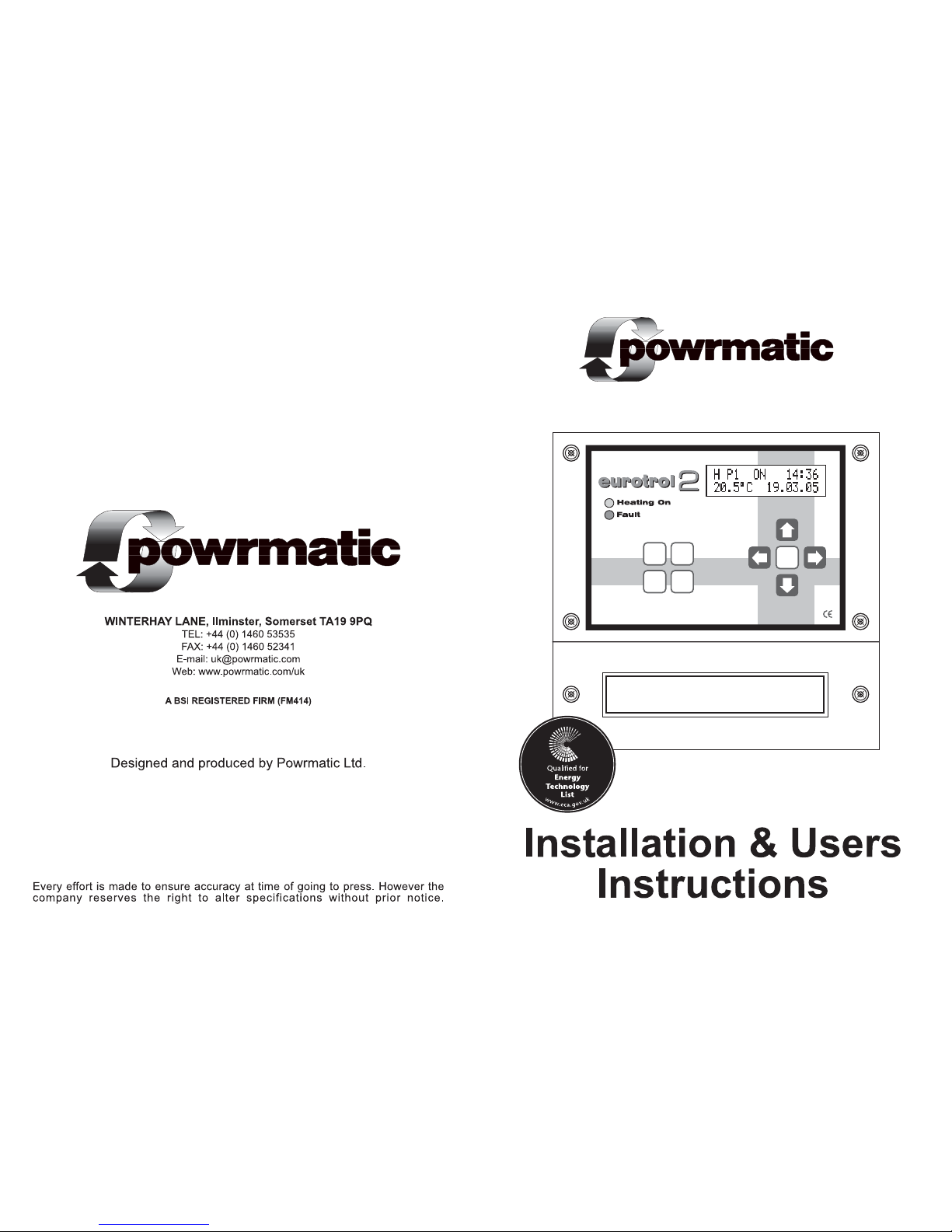
WARNING
Isolate supplies to both Eurotrol & heater
before removing this cover
powrmatic
Ltd · tel: 01460 53535 · fax: 01460 52341
www.powrmatic.co.uk · email: eurotrol@powrmatic.co.uk
Reset
Fan Only
Heating
Override
e
Page 2

2 19
Notes
Page 3

18 3
Contents
Page
4 Description
5 Specifications
Dimensions
6 Installation
Electrical Connections
7 User Keypad
Programming Keypad
8 Overview
Programming date and time
9 Basic and advanced operating modes
Heating / Fan Only modes
10 Entering the switching program
11 Advanced operation
Quick mode / temp offset
12 Menu options
14 Menu layout
16 Sensor wiring
Connection diagrams
19 Notes
Page 4

Description
The Eurotrol 2 is a high specification
heating controller designed specifically to
meet the demands of modern fuel efficient
heating equipment and the latest
environmental guidelines.
The Eurotrol 2 uses optimum start
technology as standard. It is continually
monitoring the heating systems previous
performance to determine the optimum
time to turn the heating on to raise the
building temperature to the required level
when occupancy begins.
Optimum stop can also be selected which
can save energy at the end of the heating
period.
The Eurotrol 2 has both a basic and
advanced programming mode. The basic
mode allows easy setting of the
temperature and programs. In advanced
mode different temperatures may be
selected for different times of the day and
temperatures may only be adjusted by
+/- 3°C without the use of a password.
The Eurotrol 2 is protected by 3 levels of
password. The first will allow access to
the day to day operation of the (ie. setting
times and temperatures, the second
allows access to parameters normally
used only in the initial setting of the
controller, and the third is only accessible
to field service engineers for diagnostic
purposes.
The 4 button user keypad allows easy
selection of the heating and fan only
modes, the override functions and fault
reset. These may also be locked in various
combinations to allow different levels of
user accessibility.
The Eurotrol 2 can give a readout of the
hours the burner has operated, to help
accessing servicing intervals and after
being programmed with the correct data,
can also give an indication of the running
costs of the heating appliance
174
Page 5

Specifications
General
Electricity supply 240V 50Hz Fused at 3A.
Internal Fuses F1 20mm 6A 230V.
F2 20mm 500mA 230V.
Day set point range 0 - 34°C.
Night set point range 0 - 34°C.
Temperature accuracy 0.5 °C.
Overall switching differential Adjustable 0.5 - 3.0°C.
Sensing Element Internal or remotely mounted up to 100m from
control.
Switching contacts ratings 12A. 240V.ac. (resistive). All Volt Free
Heating ON Indicator Red L.E.D.
Fault Indicator Yellow L.E.D.
Protection Rating IP20
Time Switch
Display 2 line 5mm L.C.D.
Programming Instructions 3 per day
Shortest switching time 1 minute
Battery backup 50 hrs. after 100 hrs. connected to mains.
INTERNAL SENSOR
REMOTE SENSOR
REMOTE AVERAGING SENSORS
(IN EXTENDED MENU SET No OF SENSORS TO 2 )
Sensor Wiring
A single remote sensor may be used
in place of the standard internal
sensor.
Two remote sensors may be used
which relay an average of the two
temperatures
back to the Eurotrol 2
Important
Sensor cable must be screened two
core and a minimum of 0.6mm² if
solid and 7 x 0.2mm² if multistrand.
The screen must be grounded only
at the Eurotrol 2. Wiring for the
temperature sensor MUST BE RUN
SEPARATELY and apart from ALL
other wiring. Failure to regard this
instruction may cause the Eurotrol 2
to malfunction and may render it
faulty.
Connection Diagrams
16 5
Dimensions
WARNING
Isolate supplies to both Eurotrol & heater
before removing this cover
powrmatic
Ltd · tel: 01460 53535 · fax: 01460 52341
www.powrmatic.co.uk · email: eurotrol@powrmatic.co.uk
Reset
Fan Only
Heating
Override
e
Page 6

Set number of sensors
Set length of extension time
Set quick mode ON or OFF
Set user access to front buttons
Set optimum stop temperature
Set constant fan ON or OFF
Set Hi/Low differential*
*When applicable
View run log
Set power & cost parameters
Set service date parameters
Set new extended menu password
Restricted access
6 15
Installation
IMPORTANT
The Eurotrol 2 or sensor MUST NOT be sited in areas of high electromagnetic fields,
i.e. distribution boards, transformers or heavy duty supply cables.
Eurotrol 2
Siting of the Eurotrol 2 is important in that it must be fitted where the temperature
will be generally representative of the area to be heated. It should be installed 1.7m
above floor level and away from draughty areas or areas subjected to direct heat
from sunlight, radiators etc. (Unless a remote sensor is being used)
Remote sensor (optional)
The siting of the Eurotrol 2 should be no greater than 100m from the sensor and
should be in a position easily accessible for programming and control. Siting of the
sensor is important in that it must be fitted where the temperature will be generally
representative of the area to be heated. It should be installed 1.7m above floor level
and away from draughty areas or areas subjected to direct heat from sunlight,
radiators etc.
Fixing
For fixing into wood use No.8 x 1¼ woodscrews, on masonry use screws together
with wallplugs and on metal use M5 machine screws.
Remote sensor (optional)
Remove cover and offer the sensor up to the intended mounting position and mark
two fixing holes. Fix sensor base plate to the wall.
See connection diagrams on page 16
Eurotrol 2
Remove the two screws from the terminal cover and remove. Offer the unit up to
the intended mounting position and mark the location of the three fixing holes using
the template on the packaging box Secure the top fixing leaving approximately 5mm
protruding, hang the Eurotrol 2 on the top fixing screw, line up the bottom fixing holes
and secure using two screws.
Electrical Connections
IMPORTANT
Wiring external to the Eurotrol 2 must be installed in accordance with I.E.E. Regulations
together with any local regulations which may apply. Wiring should be completed
in conduit, entry for which is provided in the bottom of the unit. See external wiring
diagram Mains supply and control circuit wiring should be completed in cables not
less than 0.5mm² and fan circuit in not less than 1.5mm². The connection to the
mains electrical supply can be taken from the appliance or a separate local supply,
but in both cases a local isolator must be fitted adjacent to the Eurotrol. Should
more than one appliance be controlled from one Eurotrol 2 a relay box MUST BE
USED.
WARNING - SENSOR WIRING
Sensor cable must be screened two core and a minimum of 0.6mm² if solid and 7
x 0.2mm² if multistrand. The screen must be grounded only at the Eurotrol 2. Wiring
for the temperature sensor MUST BE RUN SEPARATELY and apart from ALL other
wiring. Failure to regard this instruction may cause the Eurotrol 2 to malfunction
and may render it faulty.
e
e
e
e
e
e
e
e
e
e
Page 7

e
Use this button to enter data and move from a main screen to
a sub-menu.
Holding down for 5 secs. will display the run log.
Programming keypad (5 Buttons)
User keypad (4 Buttons)
Use these two buttons to
move up and down
between screens.
Use these two buttons to
increase/decrease the value.
Use these two buttons to
increase/decrease the
selected value
Use these two buttons to move
along the screen.
Default password set to
Menu Layout
Switches Eurotrol ON or OFF
Adjusts day temperature
Adjusts frost temperature
Set program times
Set holiday dates
Set current time and date
Set new main menu password
Default password set to
Set Basic or Advanced
Set temperature differential
Adjusts night temperature
Main display
14
7
A short press of either button will place the control into that respective
mode until midnight of that day. (Indicated by a flashing H for heating
or F for fan only,in the display)
Pressing either button for 5 secs. will permanently place the control
into that respective mode. (Indicated by a steady H for heating or F
for fan only, in the display)
Resets the burner from lockout, (when this facility is available), and
resets the run log to zero when used in the main menu.
Pressing once will activate the soft override (will change the programs
On or Off state until the next program step). Holding down for 5 secs
will initiate or cancel the extension time. . Used as the escape key in
the programming menus.
Heating
Fan Only
Reset
Override
e
e
e
e
e
e
e
e
e
e
e
Page 8

The eurotrol 2 comes preprogrammed with a typical heating program.
After installation the minimum setup required will be to program the current time and
date.
Power up
On initial power up a blank display followed by a partial
display will appear for up to 15 seconds before the full
display.
Programming the date and time if not correctly displayed
From the main screen
press
to enter the
password screen
Note: GMT and BST will automatically be set and will change automatically twice each year.
e
From the password
screen press
to enter the main
menu
e
Note: the factory set password is
From the main menu
screen press
5 times to enter the set
clock screen
From the set clock
screen press
to enter the setting
screen
e
Press
to adjust the hour
orPress
to adjust the hour
or
Press
to move to minutes
Press or
to adjust the minutes
Set date . month . year in a similar way. Note: day will be automatically set
Press
to enter the data and return to
the set clock screen
e
From the main menu
screen press
Press or
to move to another
screen
Overview
Optimum stop:
Set temperature differential (preprogrammed to 0ºC).
Optimum stop will switch off the heating to save energy before the end of the
program time.
Example: If the heating program calls for the building to be heated to 20ºC, but it is felt
that at the end of the heating program this temperature could drop to 18ºC with no detrimental
effect, then the optimum stop should be set to 2ºC (20ºC - 18ºC). This 2ºC will be applied
to any of the programs in use.
Note: A setting of 0ºC effectively turns optimum stop off.
Heater fan runs constantly during program times in
heating mode.
Sets the temperature differential for hi / low operation.
Note: Hi / low only available with add on module.
Sets the temperature differential for optimum stop to begin.
Displays burner hours run and approximate running cost.
Note: Run log may also be displayed from the main display py pressing and
holding for 10 secs. (Password not required)
Enters data to calculate approximate running cost.
Displays service reminder and contact phone No.
Menu only available to Powrmatic service engineers.
Constant Run Fan
Optimum Stop
High / Low Differential
Run Log
Power and Cost
Service Date
Engineer Menu
8 13
Alternatively press or wait 30secs to return to main screen
Override
e
Page 9

Basic & advanced operating modes
The eurotrol 2 is supplied in the BASIC operating mode:
This allows easy adjustment of the temperature set point after entering the first level
password and allows entering 3 switching programs per day
By selecting the ADVANCED operating mode, easy temperature set point adjustment
is limited to +/- 3°C (in the temp offset screen) without the use of a password.
The ADVANCED mode programs allow up to 3 switching programs per day each
with a different temperature set point if required.
Selecting operating mode
From the main screen
press
to enter the
password screen
e
From the password
screen press
to enter the main
menu
e
Note: the factory set password is
From the main menu
screen press
7 times to enter the
extended menu screen
From the extended
menu screen press
to enter the password
screen
e
From the main menu
screen press
Press or
to move to another
screen
From the password
screen press
to enter the
extended menu
e
Note: the factory set password is
Press or
to select basic or
advanced
Heating / Fan Only modes
A short press of either button will place the control into that
respective mode for the remainder of the day. (Indicated by a
flashing H for heating or F for fan only,in the display)
Pressing either button for 5 secs. will permanently place the
control into that respective mode. (Indicated by a steady H for
heating or F for fan only, in the display)
Fan Only
Heating
Menu options
Turns the controller On or OFF.
Adjusts the set point temperature.
Sets temperature that heater operates during
fan only, heating off times and holiday periods.
May be turned OFF
Suspends the program while the buiding is unoccupied.
Enter first day of holiday and day of return.
Sets a new password.
Sets the switching differential for all set points.
Sets temperature that heater operates during
program OFF times. May be turned OFF
Sets the number of sensors connected.
Extends the current program when
is pressed for 5 secs.
Override
Sets the level of user button access.
Run Mode
Set Temperature
Frost Temperature
Holiday Dates
New Password
Temperature Differential
Night Temperature
No. of Sensors
Extension Time
Button Access
12
9
e
Alternatively press to enter selection
Page 10

Sample program
The screens pictured below show the settings required in the ADVANCED operation
for the following program:
Monday to Friday on between 8am and 1pm controlled at 20ºC
Monday to Friday on between 2pm and 5pm controlled at 20ºC
Saturday on between 8.30am and 12pm controlled at 18ºC
1. Set MO-FR Program 1: Temp 20ºC: On 08:00 Off 13:00
Sets these times for Monday through to Friday
2. Set MO-FR Program 2: Temp 20ºC: On 14:00 Off 17:00
Sets these times for Monday through to Friday
3. Set SA Program 1: Temp 18ºC: On 08:30 Off 12.30
Sets these times and temperature for Saturday
Entering the switching program (ADVANCED OPERATION)
The ADVANCED programming is similar to BASIC operation with the addition of:
select to temporarily disable the program entry
selects the temperature for the program entry
Quick mode / temp offset (ADVANCED OPERATION)
in the extended menu select quick mode ON
during normal
operation press
Press
or
to enter the temp
offset screen
or
to adjust the
temperature by +/- 3°C
Temp offset allows the adjustment of the set point temperature to be carried out
without entering a password, allowing a limited day to day adjustment of +/- 3°C.
ie. If the temperature has been set to 20°C in the program and the temp offset is
set to +2°C then the set point will have been adjusted to 22°C (20+2=22)
Entering the switching program (BASIC OPERATION) Important: As the Eurotrol 2 is an optimum start controller
the program start time should be when occupancy begins
and no pre-heat time should be allowed for.
10
11
Individual days may be programmed with up to 3 entries (P1-P3) and a Monday to
Friday block may also be set with a further 3 entries.
Note: A basic program of Monday to Friday on at 08:00 (8am) and off at 17:00 (5pm)
and a set point temperature of 20ºC is preprogrammed into the eurotrol 2.
From the main screen
press
to enter the
password screen
e
From the password
screen press
to enter the main
menu
e
Note: the factory set password is
From the main menu
screen press
3 times to enter the
program screen
From the program
screen press
to enter the setting
screen
e
Press orPress
or
From the main menu
screen press
to alter the day (individual days
are selectable together with
MO-FR as one entry)
Press
to move to program number
Press
to select the program number
(3 programs P1-P3 are available
for each day)
Press
to move to ON hour
or
Press
to change the ON hour
Press
to move to ON minutes
Set ON minutes and OFF time in a similar way
to select the day again. Work
through subsequent days and
program nos. as required
Press
to enter the program
Press
e
Press or
to move to another
screen
e
Press
to enter selection
Alternatively press or wait 30secs to return to main screen
Override
 Loading...