

Powrmatic ErP NVS 30, ErP NVS 60, ErP NVS 90, ErP NVS 140 User, Installation & Servicing Manual
Doc Ref: M102 Issue 2.4 May 2018
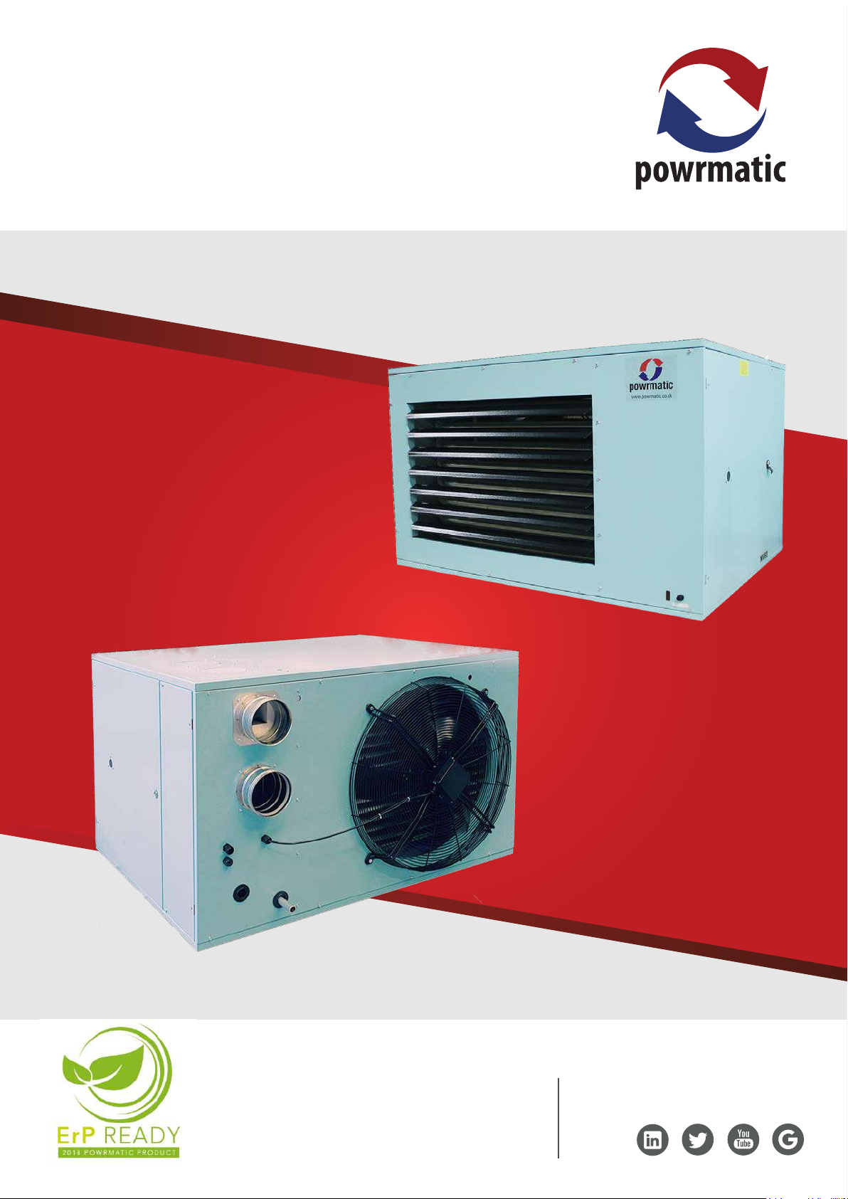
NVS Condensing Gas Unit Heater
Industrial & Commercial Heating Systems
User, Installation
& Servicing Manual
www.powmatic.co.uk
+44 (0) 1460 53535
info@powrmatic.co.uk
Certificate of Guarantee
Dear Customer
This is to certify that this heater is guaranteed for two years parts and one year labour from the date
of original commissioning. The heater must be commissioned within 4 weeks of installation.
To make a claim
In the rst instance you must contact your appliance supplier, or installer and provide:-
1. The appliance type and serial number.
2. The original commissioning documentation. As much detail as possible on the fault.
3. Your supplier, or installer, will then contact Powrmatic to make a guarantee claim on your behalf.
Conditions of Guarantee
1. The heater must have been installed by a competent recognised installer, and in
accordance with the manufacturer’s instructions, building regulations and local regulations.
2. The heater has been professionally commissioned, within 4 weeks of installation, and a copy of
the commissioning sheet returned to Powrmatic.
3. The heater has been maintained on a yearly basis by a competent servicing company.
4. The heater has been used in accordance with the manufacturer’s instructions.
5. The correct specication fuel has been used.
6. No unauthorised repairs of modications have been made. Powrmatic ‘General Conditions of
Sales’ have been observed.
7. Except for the obligation of Powrmatic Ltd to perform warranty repairs during the guarantee
period Powrmatic will not be liable in respect of any claim for direct or indirect consequential
losses, including loss of prots or increased cost arising from loss of use of the heater, or any
event arising there from.
Exclusions
Consumables such as gaskets, ignition electrodes, ame rectication electrodes, drive belts, fusible
links, control batteries are all excluded from guarantee.
----------------------------------------------------
Powrmatic Ltd, Hort Bridge, Ilminster, Somerset, TA19 9PS
Tel: 01460 53535 Fax: 01460 52341
Web: www.powrmatic.co.uk e-mail: warranty@powrmatic.co.uk
Important: This certicate
must be kept with the appliance
Failure to provide a copy of the commissioning sheet invalidates the heater warranty
Installer
Date:________________Signed: _____________________________________Installer
Commissioned
Date:________________Signed:_______________________Commissioning Engineer
page no. 2 of 36
NVS Range Users, Installation & Servicing Instructions Doc Ref M102 issue 2.4 May 2018.

Dear Customer - thank you for choosing Powrmatic.
We appreciate you buying one of our high quality products and know that you have made the best
choice. By choosing Powrmatic, you are investing in UK manufacturing & its workforce. We pride
ourselves by manufacturing products that provide clean, comfortable and safe working environments
worldwide together with the personal & professional service and back-up you deserve. If you have
any questions or concerns regarding this product, please contact our Technical Support Team by
calling 01460 53535.
Users, Installation and Servicing Instructions
CONTENTS
Title Section Contents Page
User Instructions 4
Pre Installation
1.1 Introduction 5
Duties 6
Dimensions 7
1.2 Technical data 9
1.3 General Requirements 10
Installation
2.1 Fitting the unit 14
2.2 Flue/Combustion Air Duct System 16
2.3 General Identication of Electrical Items 19
2.4 Electrical Cable Installation 19
2.5 Wiring Diagrams 21
2.6 Commissioning and Testing 23
2.7 Servicing 27
Additional Documents
3.1 Short List of Parts 30
3.2 Gas Conversion 32
Appendices
Information required for ecodesign (ErP) Directive 2009/125 34
NVS Range Users, Installation & Servicing Instructions Doc Ref M102 issue 2.4 May 2018.
page no. 3 of 36

User Instructions
If the heater has not been left operational
proceed as follows.
A) Checks before lighting the Air Heater
The following preliminary checks should be made before
lighting the heater(s)
a) Ensure that the ELECTRICAL supply to the heater is
switched OFF.
b) Check that all warm air delivery outlets are open.
c) Check that the thermostat is set at MAX.
d) Check that the clock control is set to an ON period.
e) Check that any other controls are calling for heat.
B) Lighting the Air Heater
1. Switch on the electrical supply at the isolator
2. If the Red Limit indicator light at the front of the heater is
illuminated, press the limit interlock reset switch at the side
of the lamp.
3. The startup sequence will commence.
4. If the burners fail to light the control box will
automatically restart the ignition sequence. If after 5
attempts at ignition the burners have still failed to light
the control box will go to lockout and the Red lockout light
inside the heater (or on the low level remote reset, MC200
or Powrtrol RR if tted) will be illuminated. To restart the
ignition sequence depress the reset button for about 1-2
seconds.
WARNING: If it is not possible to light the
heater after several attempts, contact the
installer or local service company.
C) To Shut Down the Air Heater
1) For Short Periods:
Turn the room thermostat to the OFF, or set to it’s lowest
setting.
D) Description of Operation
Important: The heater must NOT be
controlled by switching ON and OFF the
main electrical supply to it.
1) Standard Units
The ignition sequence commences each time the external
controls e.g. Time clock, room thermostat etc. call for
heat. The internal exhaust fan will run and, when sucient
combustion airow is proved by the air pressure switch, the
ignition spark will be generated, the main gas valve opens
and the burners light. The heater fan will automatically
start approximately 0 - 30 seconds (depending on the
setting of the internal timer) after the burners light. When
the external controls are satised the burners will be
turned o and approximately 2 - 3 minutes later the heater
fan will be automatically stopped. If the burners fail to light
the control box will make another four attempts at ignition.
2) High / Lo & Modulating Units
When the burners are alight, the heat output will be
controlled either to high re or low re or, in the case of
modulating units, to any point between high and low re;
depending on the requirements of the space being heated
and the external controls tted.
3) Summer / Winter Modes
Certain types of external controls will provide for two
modes of operation i.e.
Summer: The heater fan alone will run at the dictate of the
external controls to provide air movement.
Winter: The heater will operate normally.
4) Overheat Thermostat
This operates if high temperatures within the heater are
detected, the burners are turned o and a Red indicator
switch light on the front panel is illuminated. The fault
condition must be identied and rectied and the
thermostat manually reset. The thermostat is located
next to the indicator light and unscrewing the cover cap
exposes the reset button which can then be depressed.
2) For Long Periods:
Complete step 1 above. Wait for 5 minutes and then turn
OFF the electrical supply at the isolator.
page no. 4 of 36
NVS Range Users, Installation & Servicing Instructions Doc Ref M102 issue 2.4 May 2018.
Note: The limit thermostat(s) can only be reset
once the unit has cooled down.
Unless the cause of the fault condition is
readily obvious, for example a power cut whilst
the heater was operating, a service engineer should be
contacted.
E) Maintenance
To maintain ecient, reliable and safe operation of the
heater it must serviced by a qualied person at least
annually and preferably at the end of the heating season.
F) IMPORTANT
Free access must be maintained to and around the heater
for servicing purposes and the air supply to the heater
must not be restricted in any way. Combustible materials
must not be stored adjacent to the heater.
If at any time a gas leak is suspected, turn OFF the gas
supply at the meter and contact the local gas undertaking
immediately.
to service unless you are a competent person in the eld of
Gas and Electrical work.
If you have any safety questions reference the servicing
and installation of any of our heaters please do not hesitate
to contact our head oce for expert advice. Your safety is
paramount to us.
Gas Safety (Installation & Use) (Amendment)
Regulations
It is law that all gas appliances are
installed, adjusted and, if necessary,
converted by qualied persons* in
accordance with the current issue of the
above regulations. Failure to install appliances
correctly can lead to prosecution. It is in your own
interests and that of safety to ensure that the law is
complied with.
All Powrmatic heaters use gas and electricity to power
them, they may also contain moving parts such as pulleys
and belts. It would be hazardous to tamper with or attempt
1.1 Introduction
The NVS range are highly ecient, fully condensing, gas
red, fanned circulation air heaters that cover heat outputs
of 30kW to 140kW, have a closed combustion circuit and
are supplied complete with a ue system. They are certied
for use on Natural Gas, Group H - G20, and Propane - G31
only. Appliance Categories are Cat II2H3P (GB, IE).
The heaters are designed to be suspended from suitable
roof points or alternatively to be mounted on purpose
designed brackets and are intended primarily for heating
commercial or industrial premises. All variants are for
internal use only.
NVS heaters feature a closed combustion circuit and have
an internal exhaust fan, mounted downstream of the
heat exchanger, to evacuate the products of combustion
and draw in air for combustion. The air heater must be
connected to a ue system that is approved by Powrmatic
Ltd.
* An approved class of person listed on the gas safe
register.
are for use in air handling units. NVS units are not suitable
for siting externally.
Heaters are tted as standard with inshot burners, a fully
automatic control for ignition, ame sensing, gas supply
control and safety functions, an internal exhaust fan, main
air fan (/F and /C models), and fan/limit thermostat.
Options include High/Low or Modulating burner controls,
inlet duct connection, outlet duct connection, 30°, 45°
head, 90° outlet bend, vertical/horizontal outlet louvre
assembly and a full range of modular duct components.
IMPORTANT
Service and Maintenance Engineers shall
ensure that replacement items are tted,
adjusted and set in accordance with the
data and detail set out in these instructions. If in doubt
consult Powrmatic Technical Department.
They may be used where the atmosphere inside the
premises could be contaminated e.g. Dust, oil mist etc. but
the heaters are not airtight and therefore may not be used
in areas classied as hazardous as dened in BS 5345: Part 2
or areas subjected to signicant negative pressures due to
extract systems.
NVS/F heaters have an axial fan assembly tted at the rear
to circulate the air being heated through the formed tube
heat exchanger. NVS/C units are supplied with a centrifugal
fan and NVS/D units for use with ducted systems where the
air moving fan is by others or a centrifugal fan section is
used adjacent to or remote from the heater. NVS/DH units
NVS Range Users, Installation & Servicing Instructions Doc Ref M102 issue 2.4 May 2018.
Gas Safety (Installation & Use) Regulations 1998
It is law that all gas appliances are
installed, adjusted and, if necessary,
converted by qualied persons* in
accordance with the current issue of the
above regulations. Failure to install appliances
correctly can lead to prosecution. It is in your own
interests and that of safety to ensure that the law is
complied with.
* An approved class of person listed on the gas safe
register.
page no. 5 of 36
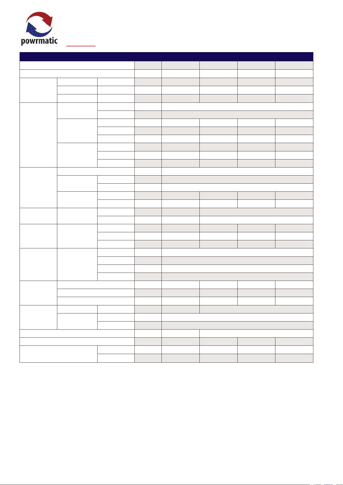
Duties
Model 30 60 90 140
Output kW 30 60 90 140
Input (nett CV) kW 29.02 59.22 86.74 137.95
Volume (All Models) m
Airflow
Throw NVS F m 24 25 31 37
Fan Static
Supply
NVS C Pa 250 250 200 285
Standard V/ph/Hz 230/1/50
Optional V/ph/Hz 415/3/50
Motor kW 0.39 0.66 2 x 0.39 2 x 0.66
Electrics
NVS F
Start amp 3.76 5.5 5.0 10.6
Run amp 1.70 2.4 2.3 5.3
Motor kW 1.10 1.40 2 x 1.10 2 x 1.40
NVS C
Start amp 18.50 28.90 31.0 40.0
Run amp 6.40 9.50 12.80 17
Connection BSP/Rc ¾”
Nat Gas mbar 17.5
LPG mbar 37.0
Nat Gas m
LPG m
Min m 2.50 3.00
Max m 3.00 5.00
Fuel
Mounting
Height
Minimum Inlet
Pressure
Consumption
NVS F
Height mm 818 818
Overall
Dimensions
NVS F
Width mm 1050 1345 2345 2345
Depth mm 1187 1204 1187 1204
Top mm 200
Installation
Clearances
NVS
LH Side mm 200
RH Side mm 1000
Rear mm 600
Connection mm 15 15 15 15
Condensate
Output
Natural Gas l/h 2.3 3.4 6.0 8.8
Propane l/h 1.2 1.7 3.0 4.4
Diameter mm ø 100 130
Flue
Maximum Length
Flue Only m 12
Room Sealed m 6
Combustion Air Spigot mm ø 100 130
Noise Level dB(A) 54 62 66 67
Nett Weight
NVS F kg 124 177 245 350
NVS C kg 195 252 384 514
3
/s 0.78 1.56 2.34 3.64
3
/h 3.07 6.26 9.17 14.60
3
/h 1.21 2.42 3.55 5.64
705 1035
Notes –
Fuel consumption and output figures based upon nett calorific values as follows
- Natural gas (G20) nett CV 34.02 MJ/m³
- Propane (G31) nett CV 88.00 MJ/m³
• Heaters have efficiency levels which meet with the minimum efficiency requirements of UK PartL2B Building Regulations
• Heaters have efficiency levels which meet the criteria of the Enhanced Capital Allowance Scheme (Excluding NVS30)
• Air handling data is assessed at room ambient conditions
• Throw figures provide the distance to the point where the terminal velocity degrades to 0.25 m/s
• Dimensions and clearance data in table above refer to NVS F units only.
• Condensate rates are approximate and for when heaters are working at maximum output.
• Noise levels are applicable to standard NVS F models and are measured 5m from appliance and in free field conditions
• Motor kW, run and start amps apply to standard electrical supply as stated. For optional data contact sales office
• Connection of combustion air duct is not required for ‘flue only’ applications.
page no. 6 of 36
NVS Range Users, Installation & Servicing Instructions Doc Ref M102 issue 2.4 May 2018.
P
Y
N
X
GAS ENTRY POINT
CONDENSATE DRAIN POINT
FRONT VIEW
PLAN VIEW
R/H SIDE VIEW
GAS ENTRY POINT
REAR VIEW
C
A
B
Q
ØD
G
F
P
N
122
394
394
M
K
J
H
SUSPENSION POINTS M10
P
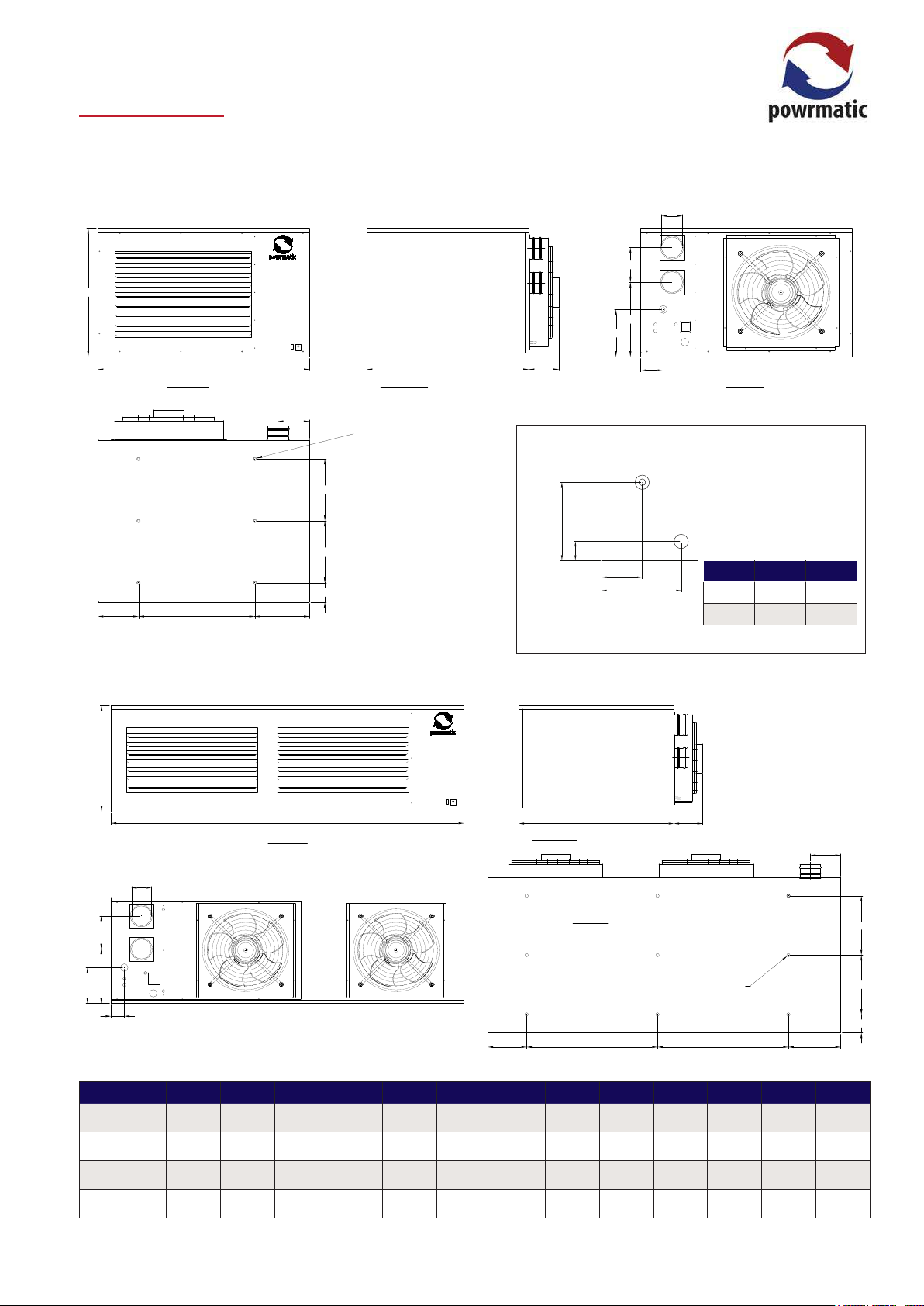
Dimensions
NVS F - Axial Fan Crossow Units
NVS 30 & 60
ØD
G
C
P
A B
FRONT VIEW
M
K
NVS 90 & 140
PLAN VIEW
J
394
394
122
H
R/H SIDE VIEW
SUSPENSION POINTS M10
Q
Detailed View Of Gas Entry Point & Condensate Drain Point
GAS ENTRY POINT
F
N
REAR VIEW
Model X Y
30/60 280 90
90/140 280 65
C
ØD
G
GAS ENTRY POINT
F
N
A
FRONT VIEW
REAR VIEW
K
B
R/H SIDE VIEW
PLAN VIEW
J J
Q
SUSPENSION POINTS M10
M
394
394
122
H
Model A B C D F G H J K M N P Q
NVS-F 30 1050 1031
818
100 552
142
347 445 258 201 144 225 156
NVS-F 60 1345 1031 818 130 475 220 347 740 258 201 144 301 173
NVS-F 90
NVS-F 140 2345 1031
NVS Range Users, Installation & Servicing Instructions Doc Ref M102 issue 2.4 May 2018.
2345
1031 705 130 356 220 347 870 258 201 88 237 156
1035
130
686
220 347 870 258 201 88 147 173
page no. 7 of 36
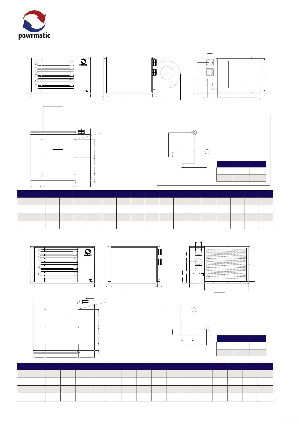
NVS C - Centrifugal Close Coupled Fan Units
P
Y
N
X
GAS ENTRY POINT
CONDENSATE DRAIN POINT
FRONT VIEW
PLAN VIEW
R/H SIDE VIEW
GAS ENTRY POINT
REAR VIEW
C
A B
63
ØD
G
F
P
N
122
394
394
M
K
J
H
SUSPENSION POINTS M10
63
L
S
R
T
P
Y
N
X
GAS ENTRY POINT
CONDENSATE DRAIN POINT
C
ØD
G
GAS ENTRY POINT
F
P
T
A B
FRONT VIEW
63
R/H SIDE VIEW
L
63
N
REAR VIEW
S
R
Detailed View Of Gas Entry Point & Condensate Drain Point
M
SUSPENSION POINTS M10
PLAN VIEW
K
J
394
394
122
H
Model X Y
30/60 280 90
90/140 280 65
Model A B C D F G H J K L M N P R S T
NVS-C 30 1050 1031
NVS-C 60 1345 1031 818 130 475 220 347 740 258 1589 201 144 301 1010 940 748
2345
1031 705 130 356 220 347 870 258 1589 201 88 237 2014 1944 635
NVS-C 90
NVS-C 140 2345 1031
NVS D - Ducted Heat Module Units (No fan)
818
1035
100 552
130
142
347 445 258 1589 201 144 225 696 626 748
686
220 347 870 258 1664 201 88 147 2014 1944 965
ØD
C
FRONT VIEW
PLAN VIEW
K
A B
J
H
63
R/H SIDE VIEW
M
SUSPENSION POINTS M10
394
394
122
63
Detailed View Of Gas Entry Point & Condensate Drain Point
G
GAS ENTRY POINT
F
P
N
REAR VIEW
S
R
T
Model X Y
30/60 280 90
90/140 280 65
Model A B C D F G H J K M N P R S T
NVS-D 30 1050 1031
818
100 552
142
347 445 258 201 144 225 696 626 748
NVS-D 60 1345 1031 818 130 475 220 347 740 258 201 144 301 1010 940 748
NVS-D 90
NVS-D 140 2345 1031
page no. 8 of 36
2345
1031 705 130 356 220 347 870 258 201 88 237 2014 1944 635
1035
130
686
220 347 870 258 201 88 147 2014 1944 965
NVS Range Users, Installation & Servicing Instructions Doc Ref M102 issue 2.4 May 2018.
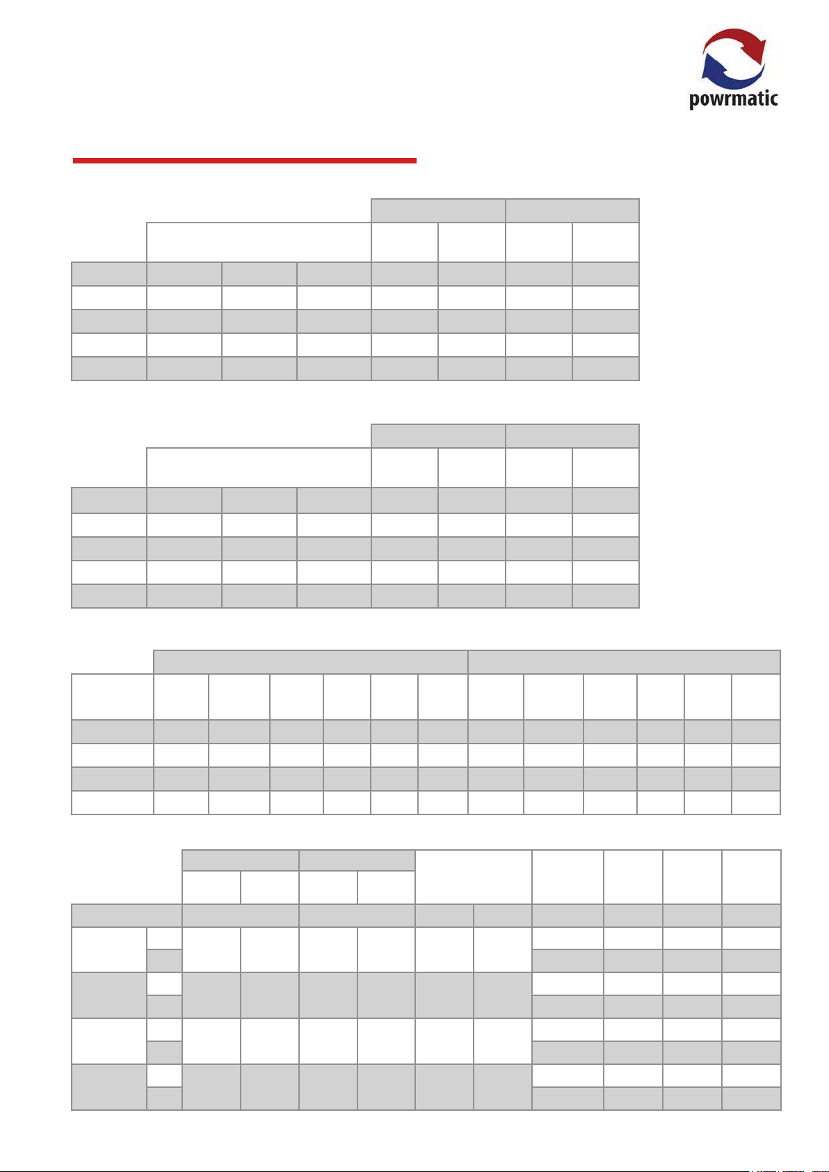
1.2 Technical Data
Injector Sizes & Burner Pressures - Natural Gas - Group H - G20 Net CV (Hi = 34.02MJ/m³)
High Fire Low Fire
Injectors
MODEL No. Size (mm)
Burner
Pressure
Marked mbar m³/h mbar m³/h
Gas Rate
Burner
Pressure
Gas Rate
NVS30 6 1.94 194 10.0 3.07 3.3 1.67
NVS60 8 2.54 254 8.3 6.26 2.6 3.46
NVS90 6 3.5 350 8.2 9.17 2.8 5.40
NVS140 10 3.5 350 7.9 14.60 2.3 8 .17
Injector Sizes & Burner Pressures - Propane G31 Net CV (Hi = 88.00MJ/m³)
High Fire Low Fire
Injectors
MODEL No. Size (mm)
Burner
Pressure
Marked mbar m³/h mbar m³/h
Gas Rate
Burner
Pressure
Gas Rate
NVS30 6 1.25 125 26.5 1.21 7.6 0.65
NVS60 8 1.55 155 20.0 2.42 7.4 1. 34
NVS90 6 2.1 210 24.0 3.55 8.4 2.08
NVS140 10 2.10 210 22.6 5.64 6.9 3.16
Electrical Loadings - 1Pha
Nominal Inlet
Pressure = 20mbar
Minimum Inlet
Pressure = 17.5mbar
Nominal Inlet
Pressure = 37mbar
Minimum Inlet
Pressure = 37mbar
Motor
MODEL
NVS30
NVS60
NVS90
NVS140
kW
0.39 930 1.8 3.76 1.7 3 1.1 900 9.8 18.5 6.4 7
0.66 860 3.0 5.5 2.8 5 1.4 930 10.0 28.9 9.5 16
2 x 0.39 930 2 x 1.8 5.0 2.3 5 2 x 1.1 900 2 x 8.0 31.0 12.8 16
2 x 0.66 860 2 x 3.0 10.6 5.3 7 2 x 1.4 900 2 x 10 40.0 17.0 20
Heater Specications
Input
(Nett)
MODEL
NVS30
NVS60
NVS90
NVS140
F
29.02 30.0 15.78 15. 2 0.7804 2809
C 250 1.1 n/a 195
F
59.22 60.0 32.72 32.29 1.5608 5618
C 250 1.4 n/a 252
F
86.74 90.0 51.00 52.53 2. 3412 8428
C 200 2 x 1.1 n/a 384
F
137.95 140.0 77.26 76.64 3.6418 13110
C 285 2 x 1.40 n/a 514
/F Models /CCF Models
Nominal
Motor
R. P.M .
High Fire Low Fire
kW kW m³/s m³/h Pa kW dB(A) kg
Output
Rated
Amps
(A)
Start
Amps
Input
(Nett)
(A)
Run
Amps
(A)
Output
Fuse
Rating
(A)
Air Volume
Motor
kW
Nominal
Motor
R. P.M .
Maximum
Resistance
Duct
Rated
Amps
(A)
Motor
Fan
Start
Amps
(A)
Amps
Noise
Level
n/a 0.39 54 124
n/a 0.66 62 176.5
n/a 2 x 0.39 66 245
n/a 2 x 0.66 67 350
Run
(A)
Fuse
Rating
(A)
Weight
NVS Range Users, Installation & Servicing Instructions Doc Ref M102 issue 2.4 May 2018.
page no. 9 of 36

1.3 General Requirements
1.3.1. Related Documents
The installation of the air heater(s) must be in accordance
with the rules in force and the relevant requirements of the
Gas Safety Regulations, Building Regulations and the I.E.E.
Regulations for Electrical Installations. It should also be in
accordance with any relevant requirements of the local gas
region, local authority and re authority and the relevant
recommendations of the following documents.
Institution of Gas Engineers & Managers
IGE/UP/1 (Ed.2) Strength and tightness testing and
purging of industrial and commercial gas installations.
IGE/UP/1A Soundness testing and direct purging of small
low pressure industrial and commercial gas installations.
IGE/UP/2 Gas installation pipe work, boosters and
compressors on industrial and commercial premises.
IGE/UP/10 (with Amendments October 2010) Installation
gas appliances in industrial and commercial premises.
British Standards Code of Practice
BS 5588 Fire precautions in the design and construction of
buildings.
Part 2 : 1985 Code of Practice for Shops
Part 3 : 1983 Code of Practice for Oce Buildings
BS 6230 Installation of Gas Fired Forced Convection Air
Heaters for Commercial and Industrial Space Heating.
Those appliances having a gross input rating not exceeding
60kW viz. NVS30 and installed to take their combustion air
from within the building must be installed in accordance
with the relevant recommendations of the following
document.
BS 5440 Flues and Air Supply for gas appliances of rated
input not exceeding 60kW (1st and 2nd family gases), Part
2 – Air Supply
For NVS30/D units, reference should also be made to:
BS 5864 Code of Practice for installation of gas-red
ducted-air heaters of rated input not exceeding 60kW.
Electromagnetic Compatibility (EMC)
These heaters pass the following standards for
Electromagnetic Compatibility: EN 61000-6-3:2007 A1
(Generic Emissions for Residential, Commercial and Light
Industrial Environments) and EN 61000-6-2:2005 (Generic
Immunity for Industrial Environments).
1.3.2 Location
Powrmatic NVS units are designed to operate within an
ambient temperature range of -10 to 25°C.
NVS heaters can be installed in several ways: i) suspended
from ‘drop rods’ via purpose designed M10 suspension
xing points on the heater, ii) attached to our optional
wall support brackets or iii) positioned on a level, noncombustible base. In all cases, it is important that all
supporting structures have been assessed with regard to
the relevant weight loadings.
Consideration should be given to ue routes and points of
exit, condensate, gas, electrical and control connections.
Consideration should also be given to the throw
characteristics of the heater, issues of public access and
siting of environmental control stations and/or remote
temperature sensors where the position needs to be
representative of the zone temperature to which they refer.
Where the location of the air heater is such that it might
suer external mechanical damage e.g. from overhead
cranes, fork lift trucks, it must be suitably protected.
Heaters should not be installed in hazardous areas or areas
where there is a foreseeable risk of ammable or corrosion
inducing particles, gases or vapours being drawn into the
combustion air or main fan circuits.
Areas where special consideration or advice may be
required could include but is not limited to –
• Where de-greasing solvents are present, even in
minute concentrations
• Where paint spraying is carried out
• Where styrenes or other laminating products are
used
• Where airborne silicone is present
• Where petrol engine vehicles are stored or main
tained
• Where dust is present (i.e. wood working or
joinery shops)
• Where high levels of extract persist
Installation in such areas may be possible under specic
conditions. Please consult our Technical Department for
further information.
1.3.2.1 Sizing of the heater
The heater should be correctly sized for the area that it is
heating, Full calculations need to be preformed to ensure
the correct KW output heater is tted (CIBSE elemental
methodology can be used, or the Powrmatic Technical
Department can provide guidelines).
page no. 10 of 36
NVS Range Users, Installation & Servicing Instructions Doc Ref M102 issue 2.4 May 2018.
1.3.3 Electrical Supply
1.3.5 Flue System
Wiring external to the air heater must be installed in
accordance with the I.E.E. Regulations for Electrical
Installations and any local regulations which apply.
All standard heaters are supplied by 230V - 1ph, 50Hz. The
method of connection to the main electricity supply must:-
- facilitate the complete electrical isolation of the unit(s)
- be in a readily accessible position adjacent to the unit(s)
- serve only the unit(s)
- have a contact separation of at least 3mm in all poles. See
the accompanying wiring diagram for the heater electrical
connections
NVS/C and fan/silencer units can also be supplied for 400V
3N, 50Hz.
1.3.4 Gas Supply
A servicing valve and union to facilitate servicing must
be tted to the gas inlet pipe work of the heater. The gas
supply must be completed in solid pipe work and be
adequately supported. Heaters suspended by drop rods,
straps or chains must have a exible connection as the
nal link between the gas supply pipe work and the heater.
Sucient slack must be left in the connection to take
account of normal movement of the heater.
Warning
When completing the nal gas connection
to the heater do not place undue strain on
the gas pipe work of the heater.
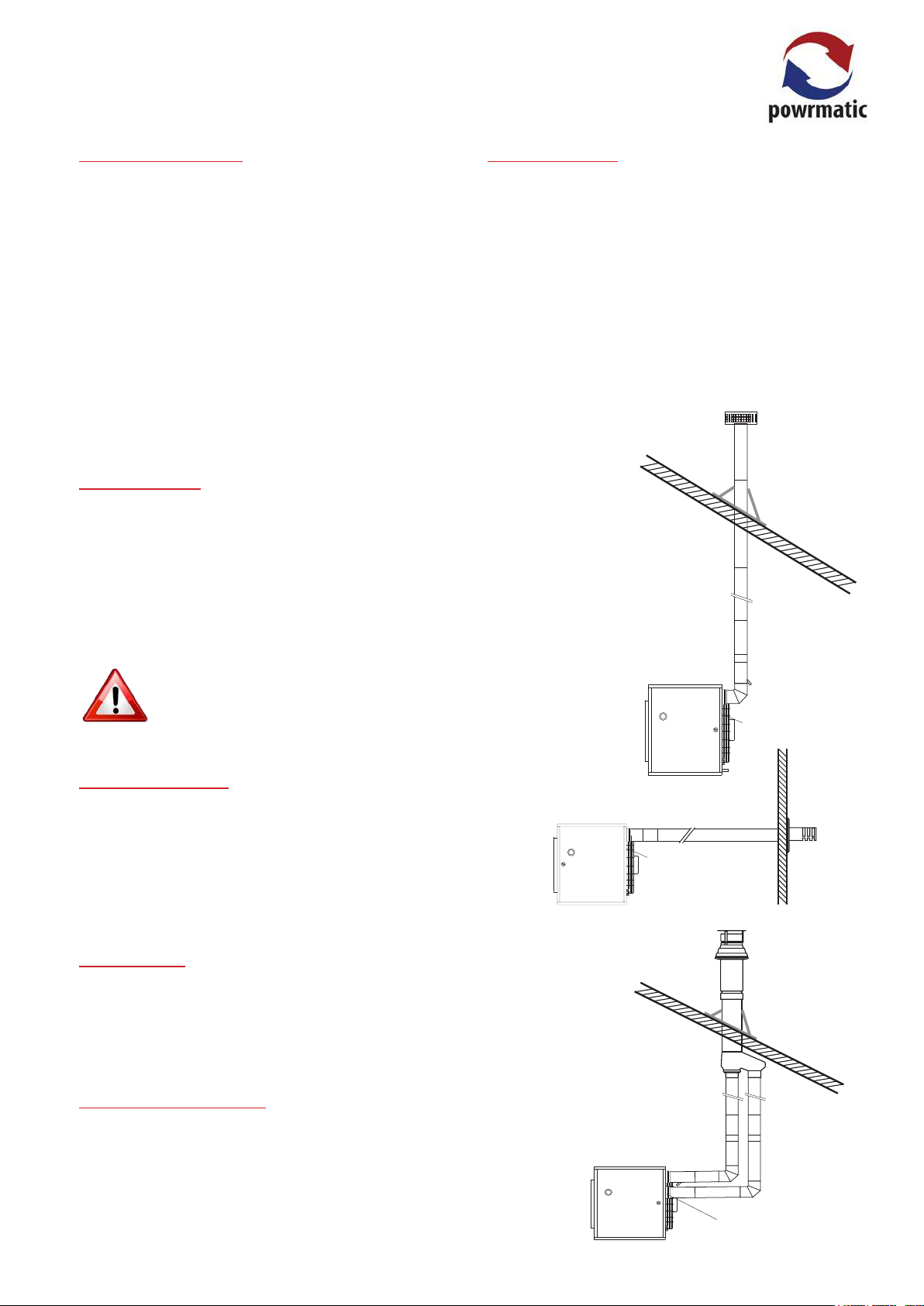
NVS units feature a closed combustion circuit and have an
internal exhaust fan, mounted downstream of the heat
exchanger, to evacuate the products of combustion and
draw in air for combustion.
The air heater must be connected to the ue system that is
provided by Powrmatic Ltd. Several congurations of ue
and combustion air ducts are available.
The ue must terminate in a freely exposed position and
be sited to prevent the products of combustion entering
any opening in a building in such concentration as to be
prejudicial to health or a nuisance
Type B22 Installation.
Combustion air entry
(fitted with inlet grille and
inlet bend (not shown))
1.3.4.1 Service Pipes
The local gas undertaking should be consulted at the
installation planning stage in order to establish the
availability of an adequate supply of gas. An existing
service pipe must not be used without prior consultation
with the local gas undertaking. The inlet gas pressure
under running conditions must not be less than 17.5mb.
1.3.4.2 Meters
An existing meter should be checked, preferably by the gas
undertaking, to ensure that the meter is adequate to deal
with the total rate of gas supply required by all connected
equipment.
1.3.4.3. Installation Pipes
Installation pipes should be tted in accordance with IGE/
UP/2. Pipe work from the meter to the air heater must be
of adequate size. Do not use pipes of a smaller size than
the inlet gas connection of the heater. The complete
installation must be tested for soundness as described in
the above Code.
Type C32 Installation.
Combustion air entry
(fitted with inlet grille and
inlet bend (not shown))
Combustion
air socke t
NVS Range Users, Installation & Servicing Instructions Doc Ref M102 issue 2.4 May 2018.
page no. 11 of 36
 Loading...