

Powrmatic CPx Series, CPx 30, CPx 120, CPx 150, CPx 175 User, Installation & Servicing Manual
...Page 1

www.powrmatic.co.uk
CPx
Doc Ref: M201 Issue 2.9 Nov 2018
®
User, Installation & Servicing Manual
Issue 2.9 November 2018
ErP COMPLIANT
SEPTEMBER 2018
Page 2

Certificate Of Guarantee
®
Certificate of Guarantee
This is to certify that this heater is guaranteed for two years parts and one year labour from the date
of original commissioning. The heater must be commissioned within 4 weeks of installation.
To make a claim
In the first instance you must contact your appliance supplier, or installer and provide:-
1. The appliance type and serial number.
2. The original commissioning documentation. As much detail as possible on the fault.
3. Your supplier, or installer, will then contact Powrmatic to make a guarantee claim on your behalf.
Conditions of Guarantee
1. The heater must have been installed by a competent qualified installer, and in
accordance with the manufacturer’s instructions, building regulations and local regulations.
2. The heater has been professionally commissioned, within 4 weeks of installation, and a copy of
the commissioning sheet returned to Powrmatic.
3. The heater has been maintained on a yearly basis by a competent and qualified servicing
company.
4. The heater has been used in accordance with the manufacturer’s instructions.
5. The correct specification fuel has been used.
6. No unauthorised repairs of modifications have been made. Powrmatic ‘General Conditions of
Sales’ have been observed.
7. Except for the obligation of Powrmatic Ltd to perform warranty repairs during the guarantee
period, Powrmatic will not be liable in respect of any claim for direct or indirect consequential
losses, including loss of profits or increased cost arising from loss of use of the heater, or any
event arising there from.
Exclusions
Consumables such as gaskets, ignition electrodes, flame rectification electrodes, drive belts, fusible
links, control batteries, oil nozzles and oil line filter elements are all excluded from guarantee.
----------------------------------------------------
Powrmatic Ltd, Hort Bridge, Ilminster, Somerset, TA19 9PS
Tel: 01460 53535 Fax: 01460 52341
Web: www.powrmatic.co.uk e-mail: warranty@powrmatic.co.uk
Important: This certificate
must be kept with the appliance
Failure to provide a copy of the commissioning sheet invalidates the heater warranty
page no. 2 of 68
CPx Range Users, Installation & Servicing Instructions Doc Ref M201 issue 2.9 Nov 2018.
Page 3

Contents
Users, Installation and Servicing Instructions
CONTENTS
Title Section Contents Page
User Instructions 4
Pre Installation
1.1 Introduction 6
Duties 7
Dimensions 8
Accessories 15
Head Plans 15
1.2 Technical data 16
1.3 General Requirements 23
Installation
2.1 Fitting the unit 27
2.2 Fitting the flue 29
2.3 General Identification of Items 29
2.4 Electrical Cable Installation 30
2.5 Wiring Diagrams 33
2.6 Commissioning and Testing 36
2.7 Servicing 40
Additional Documents
3.1 Fault Finding Flow Chart 49
3.2 List of Parts 50
3.3 Fuel Conversion 59
Appendices
1. Information required for ecodesign (ErP) Directive 2009/125 64
2. Calculation of flue system equivalent resistance 65
CPx Range Users, Installation & Servicing Instructions Doc Ref M201 issue 2.9 Nov 2018.
page no. 3 of 68
Page 4
User Instructions
If the heater has not been left operational
proceed as follows.
A) Checks before operating the Air
Heater
The following preliminary checks should be made before
lighting the heater(s)
a) Ensure that the ELECTRICAL supply to the heater is
switched OFF.
b) Check that any warm air delivery outlets are open.
c) Check that the thermostat is set.
d) Check that the clock control is set to an ON period.
e) Check that any other controls are calling for heat.
B) Operating the Air Heater
1) Gas-Fired Heaters
1. Switch on the electrical supply at the isolator.
2. The burner air fan will run and after a pre purge period
of approximately 30 seconds the ignition spark will be
generated.
CPx 30 - 90
The main gas valves will open and the main burner will be
established
CPx 120 - 300
The start gas valves will be opened and a start gas flame
established. When a start gas flame is established the
main gas valves will be energized and the start gas flame
will expand to main flame.
NOTE: If the burner fails to light it will go to
lockout and the lockout indicator / reset
button on the burner control box will be
illuminated. To restart the burner push the
reset button.
2) Oil-fired Heaters
IMPORTANT: If it is not possible to light the
heater after 2/3 attempts contact the local
service company.
1. Switch on the electrical supply at the isolator.
2. The burner air fan will run and after a pre purge period
of approximately 30 seconds the ignition spark will be
generated and the oil valve opened. The main burner will
then fire.
NOTE: If the burner fails to light it will go to
lockout and the lockout indicator / reset button
on the burner control box will be illuminated. To
restart the burner push the reset button.
If the unit will not light after two to three
attempts then shutdown the unit and call in
a service engineer.
C) To Shut Down the Air Heater
1) For Short Periods:
Turn the room thermostat to the OFF, or set to it’s lowest
setting.
2) For Long Periods:
Complete step 1 above. Wait for 5 minutes and then turn
OFF the electrical supply at the isolator.
D) Description of Operation
Important: All heaters must be controlled by the fitted
external controls and not by use of the main switch in the
electrical supply to the heater.
The burner start up sequence will commence when the
controls e.g. timeclock, room thermostat etc. call for heat.
The burner air fan will run and after a pre purge period the
burner will light.
IMPORTANT: If the unit will not light after
four or five attempts then shutdown the unit
and call in a service engineer.
WARNING: If the main burner or a start gas
flame fails to establish the burner will go to
lockout and the lockout indicator / reset
button on the burner control box will be
illuminated. To restart the burner push the lockout reset
button. Additional, more easily accessible, controls may
be fitted that mimic the lockout indicator and reset
button functions. If the unit will not light after four or
five attempts then shut down the unit and call in a
service engineer.
page no. 4 of 68
CPx Range Users, Installation & Servicing Instructions Doc Ref M201 issue 2.9 Nov 2018.
Approximately 2/3 minutes after the burner lights the
heater fan will automatically start.
When the external controls are satisfied the burner will
be turned off and approximately 4 to 5 minutes later the
heater fan will automatically stop.
1) Summer / Winter Modes
Certain types of external controls will provide for two
modes of operation i.e.
Summer: The heater fan alone will run at the
dictate of the external controls to provide
air movement.
Winter: The heater will operate normally.
Page 5
E) Fan and Limit Control
The fan and limit controls are mounted towards the top of
the air heater upper front panel.
User Instructions
Warning: Flammable Materials
i) Main Air Fan MAN/Auto
When the white button is pushed to MAN the fan will run
continuously i.e not controlled by any external controls
e.g. Timeclock. When the white button is pulled out the
fan will start and stop automatically in conjunction with
the burner.
ii) Limit Thermostat
This operates if high temperatures within the heater are
detected, the burner is turned off and a red indicator
light on the front of the heater is illuminated. The fault
condition must be identified and rectified and the
thermostat manually reset.
When the unit has cooled push the reset switch on the
front of the heater to reset the limit thermostat interlock
relay, the red indicator light will go out and the unit is
operational again.
NOTE: The limit thermostat(s) can only be
reset once the unit has cooled down. Unless
the cause of the fault condition is readily
obvious, for example a power cut whilst the
heater was operating, a service engineer
should be contacted.
F) Maintenance
Regular servicing is essential to maintain efficient, reliable
and safe operation of the heater. Users are strongly
recommended to have the heater serviced at least
annually and preferably at the end of the heating season.
IMPORTANT
Free access must be maintained to and
around the heater for servicing purposes
and the air supply to the heater must not be
restricted in any way. Combustible materials must not
be stored adjacent to the heater.
Warning: Hot Surfaces
Warning: Contains Moving Parts
Read and understand this Service Manual
Instructions before operating or servicing
this appliance
If you have any safety questions reference the servicing
and installation of any of our heaters please do not
hesitate to contact our head office for expert advice.
Your safety is paramount to us.
For gas fired heaters only:
If at any time a gas leak is suspected turn
OFF the gas supply - DO NOT USE A NAKED
FLAME - and contact the National Gas
Emergency number immediately.
Gas Safety (Installation & Use) (Amendment)
Regulations
It is law that all gas appliances are installed,
adjusted and, if necessary, converted by
qualified persons* in accordance with the
current issue of the above regulations.
Failure to install appliances correctly can lead to
prosecution. It is in your own interests and that of safety
to ensure that the law is complied with.
* Gas Safe Registered Engineer
IMPORTANT
All Powrmatic heaters use either gas or oil
plus electricity to power them, they may also
contain moving parts such as pulleys and
belts. It would be hazardous to tamper with or attempt to
service unless you are a competent person in the field of
Gas and Electrical work.
Danger: Electricity
CPx Range Users, Installation & Servicing Instructions Doc Ref M201 issue 2.9 Nov 2018.
page no. 5 of 68
Page 6

1.1 Introduction
The Powrmatic CPx range of closed flue, fanned
circulation air heaters cover a heat output range of 30
kW to 290kW and are intended primarily for heating
commercial or industrial premises.
They are B23 type appliances fitted with either a gas fired
forced draught burner or a pressure jet oil fired burner.
Fuel Types
Gas fired units are certified for use on Natural Gas, Group
H - G20, Group L - G25 and Propane - G31.
Oil fired units are supplied as standard for use with 35sec
fuel and can be supplied for use with 28sec fuel as an
option.
In accordance with guidelines from our burner supplier,
Riello, the burners fitted to Powrmatic oil-fired heaters
are suitable for fuels with a bio content of up to 10% only.
For fuels with a bio content of more than 10% please
consult our Technical Department.
CPx heaters have a centrifugal fan assembly fitted
upstream of the combustion chamber / heat exchanger
assembly to circulate the air being heated and are
available in three styles:
Standard Style
Suitable for internal applications only and available in /UF,
/UD, /HD, /HF, /CF and /CD variants (see below). /UF and
/UD models are floor standing, /HD, /HF, are horizontally
mounted on purpose design supports. /CD models can be
plinth mounted at floor level. /CF and /CD models can be
mounted at high level on purpose design supports.
/RT - Rooftop heater with outlet duct spigot on the
underside (inlet duct spigot optional).
/SD - Upright heater with side outlet duct spigot (inlet
duct spigot optional).
Other options include High/Low or modulating burners,
uprated main fan motors, flue support bracket, deep
V filters, flat panel filters, proportional air dampers,
combustion air inlet adaptors and inlet and outlet duct
spigots.
Each air heater must be connected to a closed flue system
only.
IMPORTANT
Service and Maintenance Engineers shall
ensure that replacement items are fitted,
adjusted and set in accordance with the
data and detail set out in these instructions. If in doubt
consult Powrmatic Technical Department.
For gas fired heaters only.
Gas Safety (Installation & Use) Regulations
It is law that all gas appliances are installed,
adjusted and, if necessary, converted by
qualified persons* in accordance with the
latest edition of the above regulations. Failure to install
appliances correctly can lead to prosecution. It is in your
own interests and that of safety to ensure that the law
is complied with.
* Gas Safe Registered Engineer
CPx/NCA Style
Suitable for internal applications only and having an
extended casing that encloses the burner. Available in /UF
and /UD variants only(see below).
CPx/EA Style
Casing is extended to enclose the burner. The heater is
fully weatherproof and designed for external applications
only. Available in /TD, /HD, /RT and /SD variants.
Variant types are:-
/UF - Upright heater with free blowing rotatable heads.
/UD - Upright heater with outlet duct spigot (inlet duct
spigot optional).
/HF - Horizontal heater with free blowing rotatable
heads.
/HD - Horizontal heater with outlet duct spigot (inlet duct
spigot optional).
/CF - Counterflow heater with free blowing rotatable
heads.
/CD - Counterflow heater with outlet duct spigot (inlet
duct spigot optional).
/TD - Rooftop heater with top outlet duct spigot (inlet
duct spigot optional).
page no. 6 of 68
CPx Range Users, Installation & Servicing Instructions Doc Ref M201 issue 2.9 Nov 2018.
Page 7

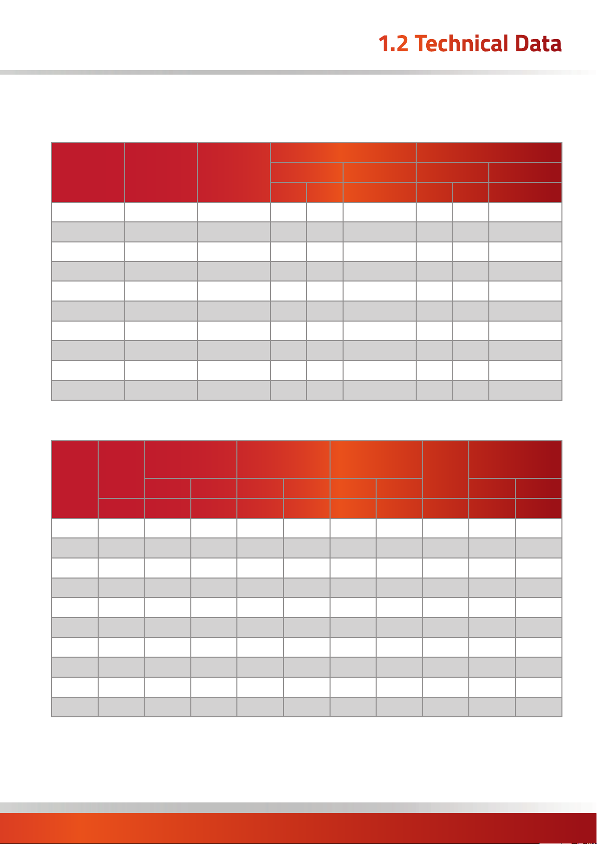
Technical Specification
CPx
Model 30 45 60 90(gas) 90(oil) 120 150 175 200 250 300 360 440 590
Output
Input (nett CV)
Old Powrmatic Reference CP 100 150 200 300 300 400 500 600 700 800 1000 1250 1500 2000
Thermal Efficiencies (Nett CV) % Min 91.5%
Heads
Airflow
Electrics
Fuel
Overall
Dimensions
Installation
Clearances
Flue Diameter mm ø 125 125 150 150 150 150 175 175 175 200 200 250 300 300
Combustion Air Spigot mm ø 150 150 150 150 150 150 150 150 150 150 150 150 175 175
Maximum Combustion Duct Length * m 34 34 21 21 21 12 8 6 4 3 2 3 2 2
Noise Level (See Note Below) dB(A) 56 61 61 63 63 70 62 73 74 75 77 78 80 82
Nett Weight (See Note Below)
Throw UF / HF m 15 21 19 24 24 24 29 29 29 41 48 48 30 40
Fan Static
Supply
Standard
Fan
Uprated
Fan (L.H.P.)
Connection
Minimum
Inlet
Pressure
Consumption
Standard
Outputs
UF Upright
Freeblowing
UF Upright
Freeblowing
G20 Gas kW 32.6 48.9 65.2 97.8 n/a 130.4 163.0 190.2 217.4 271.7 315.2 399.0 479.6 638.7
35sec Oil kW 31.9 48.7 64.3 n/a 97.7 130.5 160.3 190.3 213.3 269.4 316.1 391.6 470.8 627
Volume m
UF / HF No. 2 2 3 3 3 4 4 4 4 4 4 4 8 8
Size mm 203 254 254 305 305
Standard Pa 188 222 270 250 200 180 185 290 250 140 150 300 300 300
Up-rated Pa 250 250 400 500 450 350 400 500 500 450 500 600 600 600
Standard V/ph/Hz 230/1/50 400/3/50
Optional V/ph/Hz 400/3/50 230/1/50 n/a
Motor kW 0.55 0.55 1.1 1.5 1.4 1.4 3.0 4.0 4.0 4.0 7.5 11.0 11.0 15.0
Run amp 4.3 5.7 5.3 10.0 9.6 6.4 6.7 7.1 8.6 8.4 14.5 21.3 21.3 28.9
Start amp 8.1 17.1 16.1 25.5 28.1 12.4 23.45 23.0 19.7 28.2 50.1 127.2 127.2 182.4
Motor kW 0.75 0.75 2.2 2.2 1.5 3.0 4.0 5.5 5.5 5.5 11.0 15.0 15.0 18.5
Run amp 5.3 5.3 12.6 12.6 9.2 6.3 8.3 11.0 11.0 11.0 21.6 28.9 28.0 35.0
Start amp 15.9 15.9 37.8 37.8 27.6 22.05 29.05 38.5 38.5 38.5 75.6 182.4 182.4 221.2
Oil BSP/Rc ⅜” ⅜” ⅜” n/a ⅜” ⅜” ⅜” ⅜” ⅜” ⅜” ⅜” ⅜” ⅜” ½”
Gas BSP/Rc ½” ½” ¾” ¾” n/a ¾” 1” 1” 1” 1¼” 1¼” 1½” 1½” 1½”
Nat Gas mbar 17.5 n/a 17.5
LPG mbar 37.0 n/a 37.0
Oil l/h 3.16 4.83 6.38 n/a 9.70 12.95 15.90 18.89 21.17 26.73 31.36 38.82 47.45 63.62
Nat Gas m
LPG m
Height mm 2024 2072 2494 2585 2585 2821 2821 3054 3174 3307 3307 3657 4107 4407
Width mm 669 669 744 744 744 904 904 904 904 1104 1104 1260 1330 1330
Depth
(Excludes
burner)
Front mm 1000 1000 1000 1000 1000 1000 1000 1000 1000 1000 1000 1000 1000 1000
Side mm 1000 1000 1000 1000 1000 1000 1000 1000 1000 1000 1000 1000 1000 1000
Blank Side mm 150 150 150 150 150 150 150 150 150 150 150 n/a n/a n/a
Rear mm 1000 1000 1000 1000 1000 1000 1000 1000 1000 1000 1000 1000
Model 30 45 60 90(gas) 90(oil) 120 150 175 200 250 300 360 440 590
* For extended combustion duct lengths please contact Powrmatic
Notes –
• Fuel consumption and output figures based upon nett calorific values as follows
- Class D light distillate fuel oil nett CV 36.28 MJ/l
- Natural gas (G20) nett CV 34.02 MJ/m³
- Propane (G31) nett CV 88.00 MJ/m³
• C Px heaters comply w ith the seasonal e fficienc y and NOx limits requirements of the Ecodesig n regulation (EU) 2015/1188, Direct ive 2009/125/EC – Lot 21 Tier 1
• Air handling data is assessed at room ambient conditions
• Throw figures provide the distance to the point where the terminal velocity degrades to 0.25 m/s
• Overall vertical heater height include heads or extended heads where appropriate
• Standard height heads can be specified where site height is restricted
• Blank and louvred lower side panels are interchangeable
• Dimensions in table above refer to upright heaters only - for horizontal and counterflow heater dimensions refer to dimensions page
• Noise levels are applicable to standard UF models and are measured 5m from appliance and in free field conditions
• Motor kW, run and start amps apply to standard electrical supply as stated. For optional data contact sales office
• Nett weight figures apply to standard upright CPx heaters only
• It is the responsibility of the installing contractor to ensure that ductwork is correctly sized and balanced when installing a ducted unit.
kW 30 45 60 90 90 120 150 175 200 250 290 366 440 586
3
/s 0.97 0.86 1.01 2.11 1.50 2.30 3.15 3.36 3.84 4.49 5.76 6.49 7.88 10.5
305/358 305/358
3
/h 3.45 5.17 6.89 10.34 n/a 13.79 17.23 20.11 22.99 28.73 33.33 41.41 50.61 67.86
3
/h 1.34 1.98 2.64 4.01 n/a 5.31 6.64 7.72 8.84 11.00 12.84 16.00 19.56 26.23
mm 732 732 927 927 927 1200 1200 1399 1399 1599 1599 1915 2165 2715
kg 168 173 231 241 241 341 386 530 530 556 556 1012 1380 1720
358 406 457 457 457 457 457
1000 1000
CPx Range Users, Installation & Servicing Instructions Doc Ref M201 issue 2.9 Nov 2018.
page no. 7 of 68
Page 8
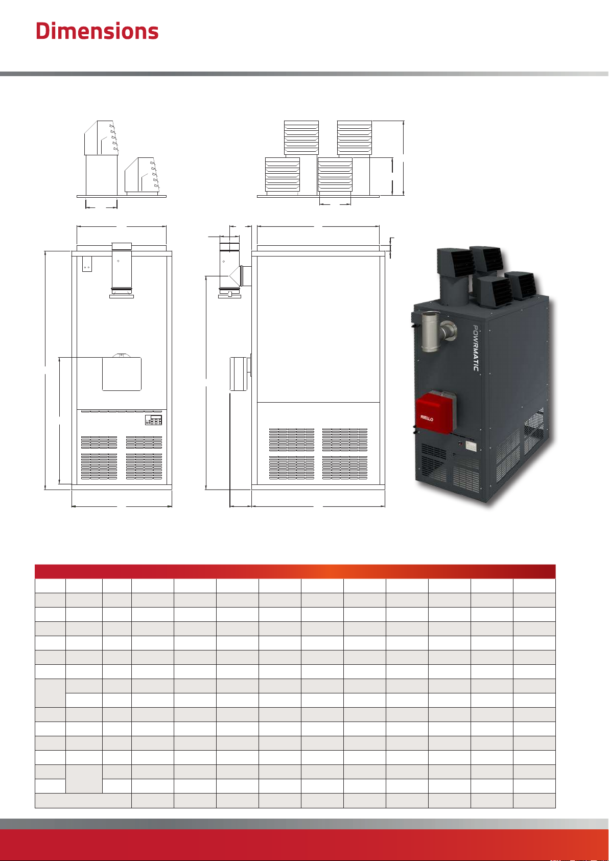
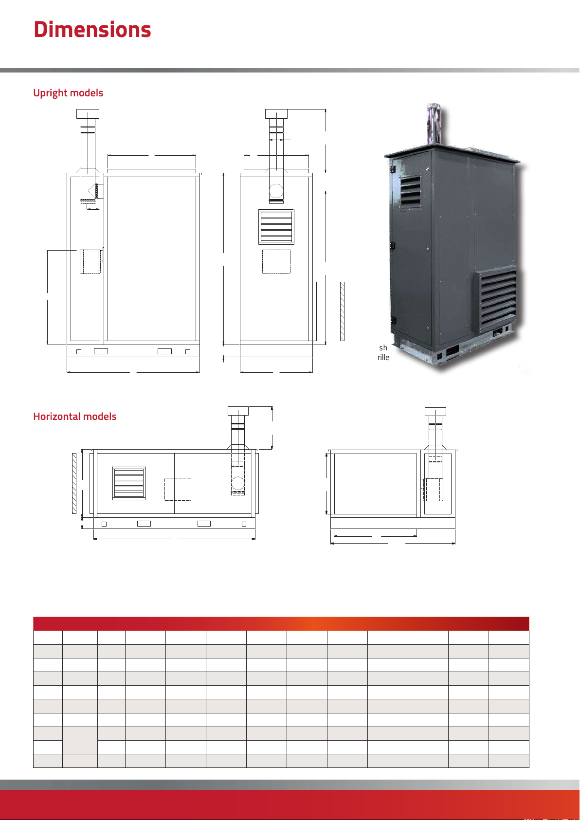
Dimensions
CPx UD/UF Upright Free Blowing Upright Ducted (30-300)
J1
J
K1
M
ØD
C
F
G
E
K
L
50
H
B
Notes -
• Flue tee provided as standard.
Model 30 45 60 90 120 150 175 200 250 300
A All mm 732 732 927 927 1200 1200 1399 1399 1599 1599
B All mm 669 669 744 744 904 904 904 904 1104 1104
C All mm 1767 1767 1895 1895 2149 2149 2265 2265 2265 2265
D All mm ø 125 125 150 150 150 175 175 175 200 200
E All mm 150 150 150 150 150 200 200 200 240 240
F All mm 1535 1535 1661 1661 1923 1923 2021 2021 2021 2021
G All mm 864 864 944 944 1122 1122 1122 1122 1122 1122
Gas mm 276 276 252 280 280 280 300 300 300 508
H
J1 All mm n/a n/a 581 672 672 672 788 875 1007 1007
K All mm 180 234 234 287 287 287 333 381 431 431
K1 All mm n/a n/a n/a n/a 333 333 n/a n/a n/a n/a
L
M mm 569 569 644 644 804 804 804 804 1004 1004
Oil mm 196 202 202 228 228 228 228 247 247 508
J All mm 238 286 286 340 340 340 400 442 558 558
Duct
Spigot
mm 632 632 824 824 1100 1100 1299 1299 1499 1499
Head Plan 1 1 2 2 3a 3a 3b 3b 3b 3b
A
page no. 8 of 68
CPx Range Users, Installation & Servicing Instructions Doc Ref M201 issue 2.9 Nov 2018.
Page 9
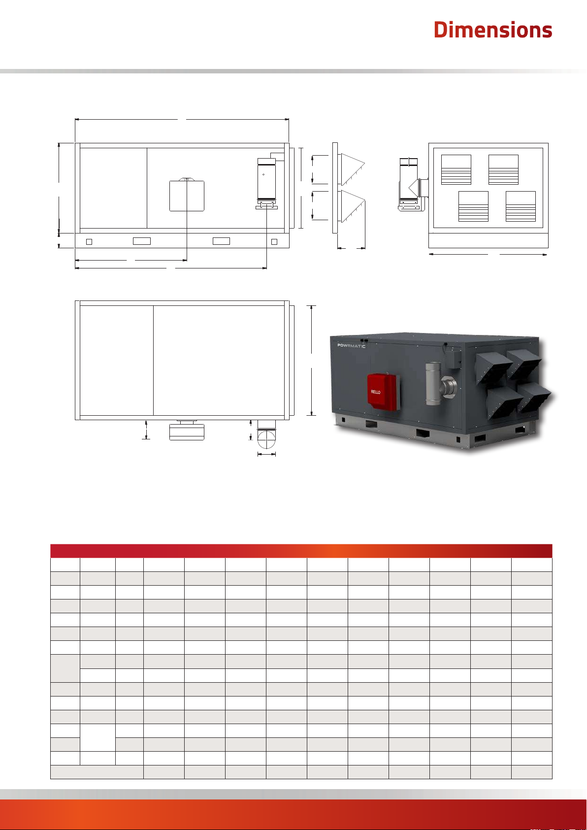
Dimensions
CPx HD/HF Horizontal Free Blowing Horizontal Ducted (30-300)
C
K1
B
N
G
F
H
E
ØD
M
K
J
L
A
Notes -
• Flue tee provided as standard.
• Screened air intake (SAI) fitted as standard on HF models. Duct spigot option available.
• Direction of airflow to be specified at time of order. Left to Right (L-R when looking at the burner) airflow shown above.
Model 30 45 60 90 120 150 175 200 250 300
A All mm 732 732 927 927 1200 1200 1399 1399 1599 1599
B All mm 669 669 744 744 904 904 904 904 1104 1104
C All mm 1767 1767 1895 1895 2151 2151 2265 2265 2265 2265
D All mm ø 125 125 150 150 150 175 175 175 200 200
E All mm 150 150 150 150 150 200 200 200 240 240
F All mm 1535 1535 1661 1661 1923 1923 2021 2021 2021 2021
G All mm 864 864 944 944 1122 1122 1122 1122 1122 1122
Gas mm 276 276 252 280 280 280 300 300 300 508
H
J All mm 227 227 260 260
K All mm 180 234 234 287 287 287 333 381 431 431
K1 All mm n/a n/a n/a n/a 333 333 n/a n/a n/a n/a
L
M mm 569 569 644 644 804 804 804 804 1004 1004
N All mm 125 125 125 125 150 150 150 150 150 150
Oil mm 196 202 202 228 228 228 228 247 247 508
260 260 297 297 367 367
Duct
Spigot
mm 632 632 824 824 1100 1100 1299 1299 1499 1499
Head Plan 1 1 2 2 3a 3a 3b 3b 3b 3b
CPx Range Users, Installation & Servicing Instructions Doc Ref M201 issue 2.9 Nov 2018.
page no. 9 of 68
Page 10
Dimensions
CPx-EA External Cabinet Heaters (30-300)
Upright models
ØD
1 mtr
E
G
Horizontal models
L
C
N
A
M
F
Optional Fresh
Air Intake Grille
B
1 mtr
Optional
Fresh Air
Intake
Grille
Notes -
• Direction of airflow to be specified at time of order. Left to Right (L-R when looking at the burner) airflow shown above.
• Inlet and Outlet duct spigots have the same dimensions (Horizontal units only)
• Primary flue length, cowl and flashing provided as standard.
A All mm 1184 1184 1379 1379 1692 1692 1891 1891 2280 2280
B All mm 669 669 744 744 904 904 904 904 1104 1104
C All mm 1767 1767 1895 1895 2149 2149 2265 2265 2265 2265
D All mm ø 125 125 150 150 150 175 175 175 200 200
E All mm 150 150 150 150 150 200 200 200 240 240
F All mm 1535 1535 1661 1661 1923 1923 2021 2021 2021 2021
G All mm 864 864 944 944 1122 1122 1122 1122 1122 1122
L
M mm 569 569 644 644 804 804 804 804 1004 1004
N All mm 125 125 125
B
N
C
Model 30 45 60 90 120 150 175 200 250 300
Duct
Spigot
mm 632 632 824 824 1100 1100 1299 1299 1499 1499
125 150 150 150 150 150 150
M
L
A
page no. 10 of 68
CPx Range Users, Installation & Servicing Instructions Doc Ref M201 issue 2.9 Nov 2018.
Page 11
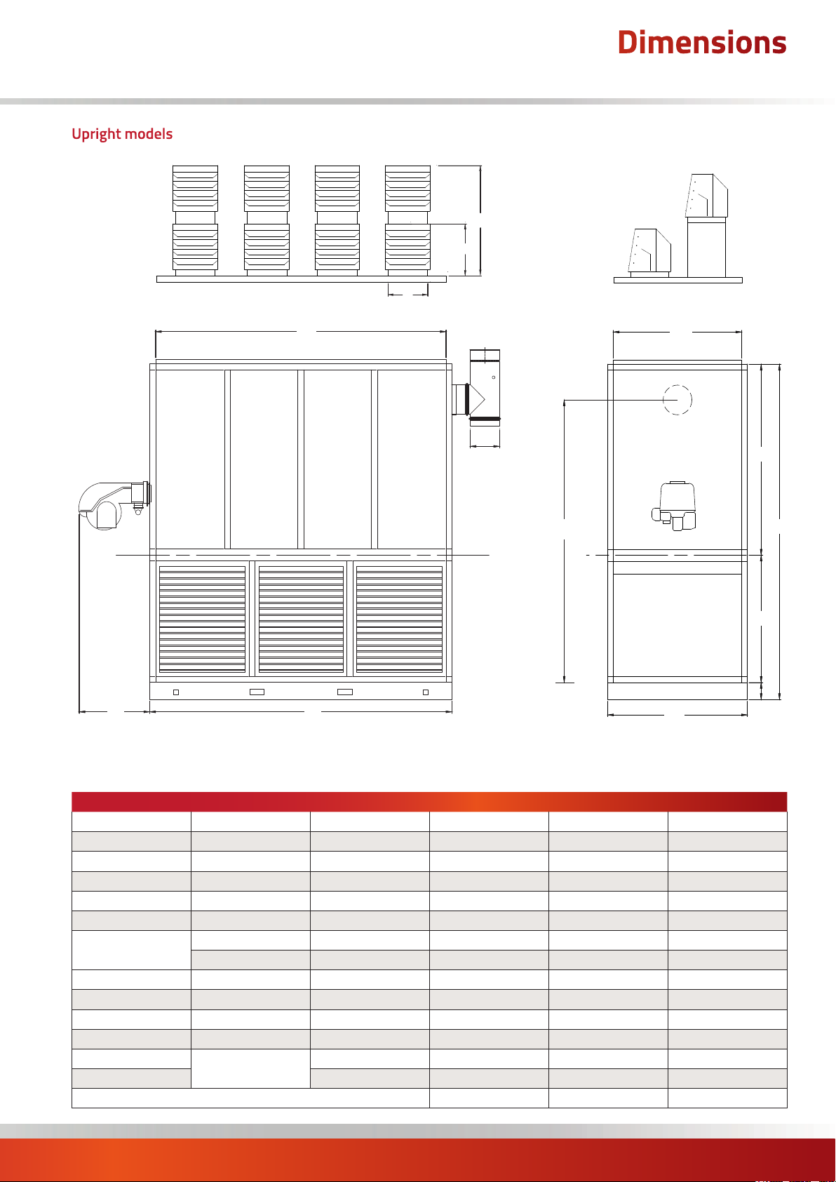
Upright models
Dimensions
CPx UD/UF Upright Free Blowing Upright Ducted (360-590)
J1
J
K
L
G
Notes -
• The Heat Exchanger and Fan Section can be split on the ‘Section Split Line’.
• Flue tee provided as standard.
A
ØD
Section
Split Line
M
F
H
B
C
E
200
Model 360 440 590
A All mm 1915 2165 2715
B All mm 1260 1330 1330
C All mm 2615 3065 3365
D All mm ø 250 300 300
E All mm 865 965 1265
F All mm 1550 1900 1900
G
H All mm 2152 2537 2837
J All mm 558 558 558
J1 All mm 1007 1007 1007
K All mm 431 431 431
L
M mm 1160 1230 1230
Gas mm 508 580 840
Oil mm 508 468 680
Duct Spigot
mm 1815 2065 2615
Head Plan 3b 4 4
CPx Range Users, Installation & Servicing Instructions Doc Ref M201 issue 2.9 Nov 2018.
page no. 11 of 68
Page 12
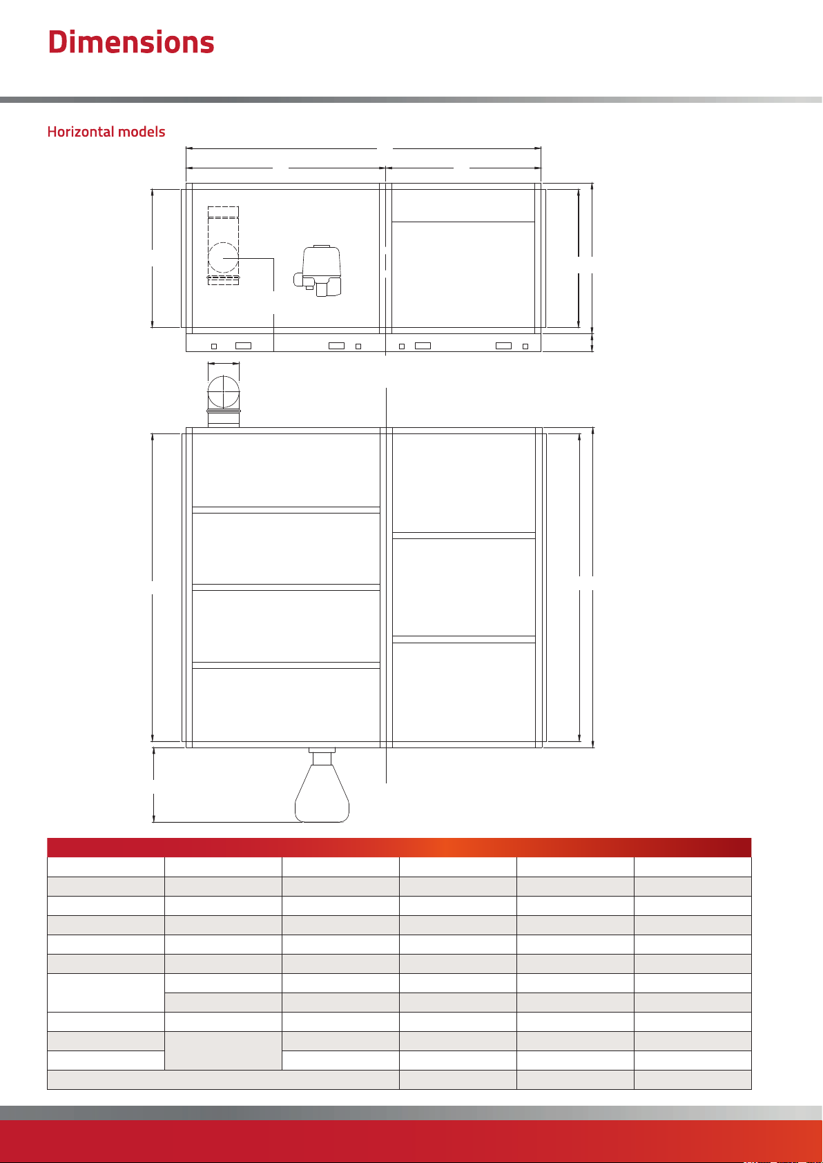
Dimensions
CPx HD/HF Upright Free Blowing Upright Ducted (360-590)
Horizontal models
M
ØD
C
F
H
Section
Split Line
E
M B
200
L
L
Notes -
G
Model 360 440 590
A All mm 1915 2165 2715
B All mm 1260 1330 1330
C All mm 2800 3250 3600
D All mm ø 250 300 300
E All mm 1250 1350 1700
F All mm 1550 1900 1900
G
H All mm 830 865 865
L
M mm 1160 1230 1230
Gas mm 580 580 840
Oil mm 468 468 680
Duct Spigot
mm 1815 2065 2615
Head Plan 3b 4 4
• The Heat Exchanger and Fan Section can be split on the ‘Section Split
Line’. Flue tee provided as standard.
• Direction of airflow to be specified at time of order.
Right to Left (R-L when looking at the burner) airflow shown above.
A
page no. 12 of 68
CPx Range Users, Installation & Servicing Instructions Doc Ref M201 issue 2.9 Nov 2018.
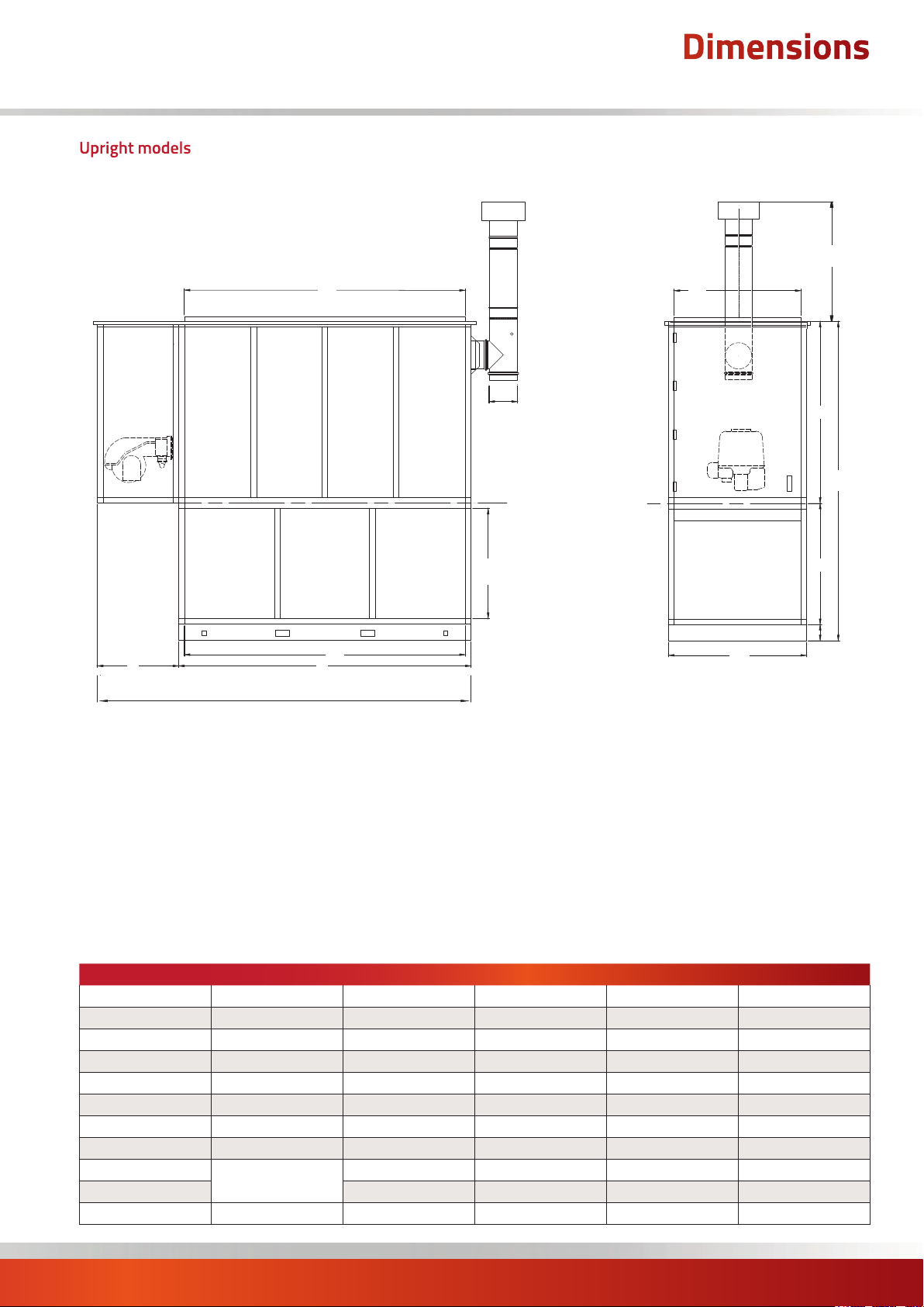
Page 13
H
Upright models
Dimensions
CPx-EA External Cabinet Heaters (360-590)
1 mtr
L
ØD
Section
Split Line
P
L
G
A
H
M
F
C
E
200
B
Notes -
• The Heat Exchanger and Fan Section can be split on the ‘Section Split Line’.
• Return air via inlet duct spigot is standard. Optional fresh air grille is available.
• Primary flue and cowl provided as standard.
Model 360 440 590
A All mm 1915 2165 2715
B All mm 1260 1330 1330
C All mm 2615 3065 3365
D All mm ø 250 300 300
E All mm 865 965 1265
F All mm 1550 1900 1900
G All mm 650 650 950
H All mm 2565 2815 3665
L
M mm 1160 1230 1230
P All mm 760 860 1160
Duct Spigot
mm 1815 2065 2615
CPx Range Users, Installation & Servicing Instructions Doc Ref M201 issue 2.9 Nov 2018.
page no. 13 of 68
Page 14

Dimensions
CPx-EA External Cabinet Heaters (360-590)
Horizontal models
1 mtr
M
L
ØD
F
C
Section
Split Line
Section
Split Line
E
M
B
200
A
L
H
G
Notes -
• The Heat Exchanger and Fan Section can be split on the ‘Section Split Line’. Primary flue and cowl provided as standard.
• Direction of airflow to be specified at time of order. Right to Left (R-L when looking at the burner) airflow shown above.
Model 360 440 590
A All mm 1915 2165 2715
B All mm 1260 1330 1330
C All mm 2800 3250 3600
D All mm ø 250 300 300
E All mm 1250 1350 1700
F All mm 1550 1900 1900
G All mm 650 650 950
H All mm 2565 2815 3665
L
M mm 1160 1230 1230
Duct Spigot
mm 1815 2065 2615
page no. 14 of 68
CPx Range Users, Installation & Servicing Instructions Doc Ref M201 issue 2.9 Nov 2018.
Page 15
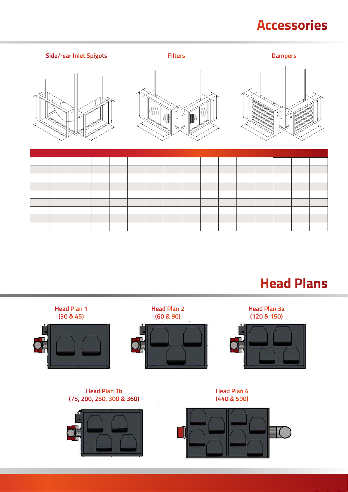
Accessories
Side/rear Inlet Spigots Filters Dampers
50
G
SIDE REAR
C
50
H
D
J
E
G
SIDE REAR
C
A
J
F
H
D
B
K
E
G
SIDE REAR
C
A
Model 30 45 60 90 120 150 175 200 250 300 360 440 590
A All mm 732 732 927 927 1200 1200 1399 1399 1599 1599 1915 2165 2715
B All mm 669 669 744 744 904 904 904 904 1105 1105 n/a n/a n/a
C All mm 630 630 825 825 1098 1098 1300 1300 1500 1500 1815 2065 2615
D All mm 567 567 642 642 802 802 802 802 1003 1003 n/a n/a n/a
E All mm 685 685 738 738 838 838 838 838 838 838 865 965 1265
F All mm 627 627 677 677 775 775 775 775 775 775 n/a n/a n/a
G All mm 585 585 640 640 738 738 738 738 738 738 765 865 1165
H All mm 527 527 577 577 675 675 675 675 675 675 n/a n/a n/a
J All mm 136 136 136 136 136 136 136 136 136 136 250 250 250
Notes -
• All dimensions are outside dimensions
• Vertical units shown - for horizontal units please contact our sales office
• Standard filter specification is 10ppi
• Higher specification filters available on request - contact our sales team for more information
• Standard dampers are manual operation - motorised options available
K
F
H
D
B
Head Plan 1
(30 & 45)
Head Plan 3b
(75, 200, 250, 300 & 360)
Head Plan 2
(60 & 90)
Head Plans
Head Plan 3a
(120 & 150)
Head Plan 4
(440 & 590)
CPx Range Users, Installation & Servicing Instructions Doc Ref M201 issue 2.9 Nov 2018.
page no. 15 of 68
Page 16
1.2 Technical Data
Riello Burner Settings - Natural Gas - Group H - G20 Net CV (Hi = 34.02MJ/m³)
Nominal Inlet Pressure = 20mbar
Minimum Inlet Pressure = 17.5mbar
High Fire Low Fire
MODEL Burner Type Gas Control
CPx30 BS1D MB405/2 3.4 3.45 1.5 2.11
CPx45 BS1D MB405/2 6.4 5.00 2.5 2.85
CPx60 BS2D MB407/2 5.8 6.89 2.5 4. 32
CPx90 BS3D MB407/2 4.2 10.34 1.9 6.82
CP x120 BS3D M B 407/ 2 6.0 13. 47 2.6 8 . 61
CP x150 BS3D MB 410/2 9.1 17. 23 3.3 10.02
CP x175 BS4D MB410/2 8.3 20.10 3.5 13.90
CPx200 RS5D MB410/2 6.9 22.99 4.1 16.15
CPx250 RS5D MB 412/2 9.3 28.46 5.8 14.38
CPx300 RS34 MZ MBDLE415 tbc tbc tbc tbc
MODEL
Head
Setting
no.
Combustion Air
Pressure
High Fire Low Fire High Fire Low Fire High Fire Low Fire High Fire Low Fire
Burner Pressure Gas Rate Burner Pressure Gas Rate
mbar m/h mbar m/h
Air
Switch*
Flue
Pressure
Switch*
Nominal CO2
(±0.5)
Nox Nett Flue Temp
No. No. No. mbar Pa % % ppm ppm °C °C
CPx30 1 2.8 1.0 2.1 40 9.2 8.75 24.7 26.8 132 74
CPx45 4 6.0 1.0 2.7 20 8.7 9 .1 23.5 29.4 171 75
CPx60 4 2.0 1.0 2.0 120 8.75 9.0 27. 9 28.8 145 78
CPx90 1 1.3 0.25 3.0 110 8.8 9.3 27. 5 33.2 154 92
CPx120 5 2 .1 1.0 5.0 280 9.2 8.8 34.5 31.9 174 102
CPx150 7 5.0 1.1 5.0 220 9.3 9.2 29.5 35.5 165 82
CP x175 7 5.3 1.8 3.6 270 9.3 8.6 28.4 32.3 158 89
CPx200 0 (39) (22) 4.0 300 9.0 8.8 41.4 40.0 141
CPx250 10 (63) (30) 4.0 300 8.8 8.4 44.0 44.3 142 79
CPx300 tbc tbc tbc tbc tbc tbc tbc tbc tbc tbc tbc
Notes: CO2 values and Nett flue gas temperatures are given for guidance and measured values will depend on site conditions.
* Air Pressure Switch settings are given for guidance and measured values will depend on site conditions.
97
page no. 16 of 68
CPx Range Users, Installation & Servicing Instructions Doc Ref M201 issue 2.9 Nov 2018.
Page 17
Riello Burner Settings - Propane G31 Net CV (Hi = 88.00MJ/m³)
Nominal Inlet Pressure = 37mbar
Minimum Inlet Pressure = 37mbar
High Fire Low Fire
1.2 Technical Data
MODEL Burner Type Gas Control
CPx30 BS1D MB405/2 5.0 1.33 2.7 0.91
CPx45 BS1D MB405/2 10.2 1.93 3.9 1.1
CPx60 BS2D M B4 07/ 2 8.2 2.67 3.5 1.67
CPx90 BS3D MB 407/2 5.5 4.0 2.6 2.64
CPx120 BS3D MB 4 07/2 7.6 5.21 3.5 3.33
CPx150 BS3D M B 410/2 10.6 6.66 4.4 3.87
CP x175 BS4D MB 410/2 tbc tbc tbc tbc
CPx200 RS5D M B410/ 2 6.9 8.8 3.9 6.24
CPx250 RS5D MB 412/2 10.0 11.0 4.7 7.49
CPx300 RS34MZ MBDLE415 tbc tbc tbc tbc
MODEL
Head
Setting
no.
Combustion Air
Pressure
High Fire Low Fire High Fire Low Fire High Fire Low Fire High Fire Low Fire
Burner Pressure Gas Rate Burner Pressure Gas Rate
mbar m/h mbar m/h
Air
Switch*
Flue
Pressure
Switch*
Nominal CO2
(±0.5)
Nox Nett Flue Temp
No. No. No. mbar Pa % % ppm ppm °C °C
CPx30 3 1.1 1.0 1.5 60 9.6 9.0 40.5 40.0 118 73
CPx45 4 6.0 1.4 2.7 100 10.9 10.3 35.4 40.4 166 82
CPx60 3 2.3 1.0 2 150 9.5 9.8 29.2 47.7 160 81
CPx90 2 1.3 0.5 3 110 10.5 9.95 46.2 48.8 148 94
CPx120 4 2 .1 0.9 5 280 10.73 9.9 50.3 49.5 177 122
CPx150 6 3.6 1.0 4 220 10.9 10.26 46.8 48.0 137 73
CP x175 tbc tbc tbc tbc tbc tbc tbc tbc tbc tbc tbc
CPx200 2 39 29 4 300 10.33 9.9 64 53.0 140
CPx250 7 50 21 3 300 11.1 11.1 74 75.0 125 72
CPx300 tbc tbc tbc tbc tbc tbc tbc tbc tbc tbc tbc
Notes: CO2 values and Nett flue gas temperatures are given for guidance and measured values will depend on site conditions.
* Air Pressure Switch settings are given for guidance and measured values will depend on site conditions.
105
CPx Range Users, Installation & Servicing Instructions Doc Ref M201 issue 2.9 Nov 2018.
page no. 17 of 68
Page 18
1.2 Technical Data
Riello Burner Settings - 35sec Oil - Diesel - Net CV (Hi = 42.69MJ/kg)
High Fire Low Fire
MODEL Burner Type Nozzle
CPx30 RG1RKD 0.65 x 80S 13.44 195 2.70 8.96 130 1.89
CPx45 RG2D 1.00 x 60S 14.48 210 4.15 8.96 130 3.27
CPx60 RG2D 1.25 x 60S 14 .13 205 5.36 8.96 130 4.07
CPx90 RG3D 2.00 x 60S 13.79 200 8.28 8.27 120 6 .16
CPx120 RG3D 2.75 x 60S 12.07 175 10.91 8.96 130 8.50
CPx150 RG3D 3.00 x 60S 15.17 220 13.45 8.96 130 9.82
CP x175 RG4D 3.75 x 60B 15 .17 220 16.45 8.27 120 11.59
CPx200 RG5D 2.5 + 2.0 x 60S 13 .10 190 17. 9 6 13.10 190 10.01
CPx250 RG5D 3.0 + 2.5 x 60S 13.1 0 190 23.69 13 .10 190 13.07
CPx300 RL34 MZ TC 4.0 + 2.75 x 60S 11.03 160 25.30 11.03 160 15.00
MODEL
Head
Setting
no.
Combustion Air Nominal CO (±0.5) Nox
High Fire Low Fire High Fire Low Fire High Fire Low Fire High Fire Low Fire
Burner Pressure Fuel Input Burner Pressure Fuel Input
bar psi kg/h bar psi kg/h
Nett Flue Temp
Smoke
No. No. No. % % ppm ppm No. °C °C
CPx30 1.3 1.5 0.25 11. 8 12.5 67. 5 65.5 0 -1 133 96
CPx45 0 1.1 0.25 12.5 12.6 70.3 65.3 0-1 209 138
CPx60 2 1.9 0.45 12.7 12.6 74.5 65.0 0 -1 158 110
CPx90 0.5 0.8 0.2 12.5 12.5 80.3 68.2 0 -1 214 138
CPx120 3 1.6 0.4 12.7 12.5 57.6 4 9 .1 0-1 213 169
CPx150 5 2.9 0.8 12.7 12. 2 65.3 49.9 0-1 182 139
CP x175 3 4.2 0.5 13.0 11. 8 68.5 51.8 0-1 213 146
CPx200 6 4.0 0.4 12.4 12.1 91.2 65.8 0 -1 157 79
CPx250 8 6.0 0.6 12.7 12.4 83.6 62.4 0 -1 219 117
CPx300 6 (70) (30) 12.6 12.1
Notes: CO values and Nett flue gas temperatures are given for guidance and measured values will depend on site conditions.
* Air Pressure Switch settings are given for guidance and measured values will depend on site conditions.
tbc tbc 0 -1 tbc tba
page no. 18 of 68
CPx Range Users, Installation & Servicing Instructions Doc Ref M201 issue 2.9 Nov 2018.
Page 19
1.2 Technical Data
Riello Burner Settings - 28sec Oil - Kerosene - Net CV (Hi = 47.00MJ/kg)
High Fire Low Fire
MODEL Burner Type Nozzle
CPx30 RG1RKD 0.75 x 60S 10.0 140 2.70 7. 0 100 1.89
CPx45 RG2D 1.25 x 60S 10.0 140 4.15 7.0 100 3.27
CPx60 RG2D 1.50 x 60S 10.0 140 5.36 7.0 100 4.07
CPx90 RG3D 2.50 x 60S 10.0 140 8.28 7.0 100 6 .16
CPx120 RG3D 3.00 x 60S 10.0 140 10.91 7.0 100 8.50
CPx150 RG3D 3.75 x 60B 10.0 140 13.45 7. 0 100 9.82
CP x175 RG4D 4.50 x 60B 10.0 140 16.45 7.0 100 11.60
CPx200 RG5D 2.5 + 2.0 x 60S 10.0 140 17.9 6 10.0 140 10.00
CPx250 RG5D 3.5 + 3.0 x 60S 10.0 140 23.69 10.0 140 13.10
CPx300 RL34 MZ TC
Head
MODEL
Setting
no.
High Fire Low Fire High Fire Low Fire High Fire Low Fire High Fire Low Fire
Combustion Air Nominal CO (±0.5) Nox
4.5x60B + 3x60S
Burner Pressure Fuel Input Burner Pressure Fuel Input
bar psi kg/h bar psi kg/h
tbc tbc tbc tbc tbc tbc
Nett Flue Temp
Smoke
No. No. No. % % ppm ppm No. °C °C
CPx30 1.3 1.5 0.25 11. 8 12.5 67. 5 65.5 0 -1 133 96
CPx45 0 1.1 0.25 12.5 12.6 70.3 65.3 0-1 209 138
CPx60 2 1.9 0.45 12.7 12.6 74.5 65.0 0 -1 158 110
CPx90 0.5 0.8 0.2 12.5 12.5 80.3 68.2 0 -1 214 138
CPx120 3 1.6 0.4 12.7 12.6 57.6 4 9 .1 0-1 213 169
CPx150 5 2.9 0.8 12.7 12. 2 65.3 49.9 0-1 182 139
CP x175 3 4.2 0.5 13.0 11. 8 68.5 51.8 0-1 213 146
CPx200 6 4.0 0.4 12.4 12.1 91.2 65.8 0 -1 157 79
CPx250 8 6.0 0.6 12.7 12.4 83.3 62.4 0-1 219 117
CPx300 tbc tbc tbc tbc tbc
Notes: CO values and Nett flue gas temperatures are given for guidance and measured values will depend on site conditions.
* Air Pressure Switch settings are given for guidance and measured values will depend on site conditions.
tbc tbc tbc tbc tbc
CPx Range Users, Installation & Servicing Instructions Doc Ref M201 issue 2.9 Nov 2018.
page no. 19 of 68
Page 20
1.2 Technical Data
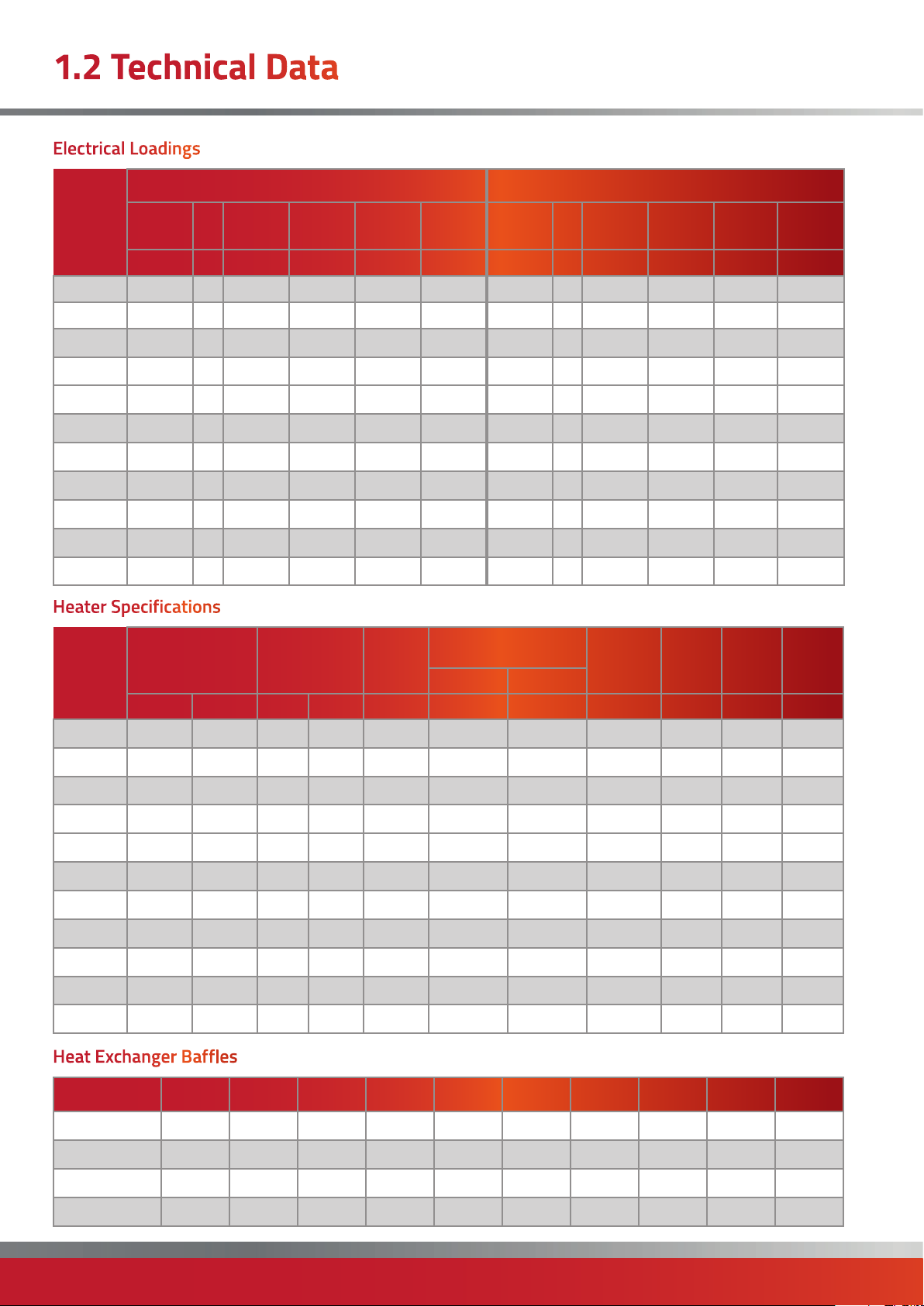
Electrical Loadings
Standard Motor Uprated Motor (fitted to EA models as standard)
MODEL
CPx30 0.55 1 1500 8.1 4.3 6 0.75 1 1500 15.9 5.3 6
CPx45 0.55 1 1500 17.1 5.7 10 0.75 1 1500 15.9 5.3 6
CPx60 1.1 1 1000 16 .1 5.3 6 2.2 1 1500 3 7. 8 12.6 16
CPx90G 1.5 1 1500 25.5 10.0 16 2.2 1 1500 37. 8 12.6 16
CPx90O 1.4 1 1000 2 8 .1 9.6 16 1.5 1 1500 27.6 9.2 16
CPx120 1.7 3 1000 12.4 6.4 10 3.0 3 1500 22.05 6.3 10
CPx150 3.0 3 1500 23.5 6.7 10 4.0 3 1500 29.05 8.3 10
CP x175 4.0 3 1500 23.0 7.1 10 5.5 3 1500
CPx200 4.0 3 1500 19.7 8.6 10 5.5 3 1500 38.5 11.0 16
CPx250 4.0 3 1500 28.2 8.4 10 5.5 3 1500 38.5 11.0 16
CPx300 7.5 3 1500 5 0.1 14.5 16 11.0 3 150 0 75.6 21.6 32
Motor Pha
kW r.p.m A A A kW r.p.m A A A
Nominal
Motor
Start
Amps
Run
Amps
Fuse
Rating
Motor Pha
Nominal
Motor
Start
Amps
38.5 11.0 16
Run
Amps
Heater Specifications
MODEL
Air Volume
(UF/HF)
m³/s m ³/h qty mm m Pa Pa dB(A) kg kg kg
Heads
Throw
(UF/
HF)
Max Duct Resistance
Std Motor Uprated
Noise
Level (std
UF/HF)
Weight
CPx
Weight
CPX/
NCA
Fuse
Rating
Weight
CPx/
EA
CPx30 0.97 3492 2 203 15 188 250 67.7 168 tbc tbc
CPx45 0.86 3096 2 254 21 222 250 35.8 173 tbc tbc
CPx60 1.01 3636 3 254 19 270 400 63.9 231 tbc tbc
CPx90G 2.11 7596 3 305 24 250 500 70.5 241 tbc tbc
CPx90O 1.50 5400 3 305 24 200 450 69.2 241 tbc tbc
CPx120 2.30 8280 4
CPx150 3.15 113 40 4
CP x175 3.36 12096 4 256 29 290 500 71.0 530 tbc tbc
CPx200
CPx250 4.49 16164 4 457 41 140 450 72.7 556 tbc tbc
CPx300 5.76 20736 4 457 48 150 500 77. 0 556 tbc tbc
3.84 13824 4 406 29 250 500 72.0 530 tbc tbc
305/358
305/358
24 180 350 71.5 341 tbc tbc
29 185 400 70.0 386 tbc tbc
Heat Exchanger Baffles
Model 30 45 60 90 120 150 175 200 250 300
Nat Gas G20 None Top tubes Top tubes All tubes Top tubes All tubes Top t u b es All tubes All tubes All tubes
Propane G31 None Top tubes Top tubes All tubes Top tube s All tubes Top tubes All tubes All tubes All tubes
Oil - 35 sec None None None Top tubes None To p t ubes None Top tubes None Top t ubes
Oil - 28 sec None None None Top tubes None All tubes None Top t ubes None Top tubes
page no. 20 of 68
CPx Range Users, Installation & Servicing Instructions Doc Ref M201 issue 2.9 Nov 2018.
Page 21
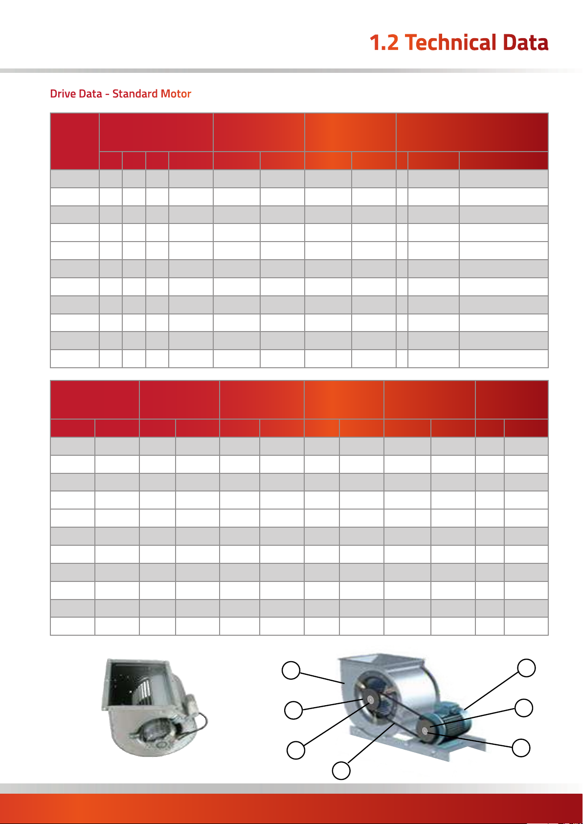
Drive Data - Standard Motor
1.2 Technical Data
MODEL
CPx30
CPx45
CPx60
CPx90G
CPx90O
CPx120
CPx150
CP x175
CPx200
CPx250
CPx300
Fan Pulley (e)
Motor (a) Motor Pulley (b)
kW Pha RPM Pt no. Size Pt no. Size Pt no.
0.55 1 1500 n/a n/a n/a n/a n/a 1 270 x 270 1402CFAN150/T/15
0.55 1 1500 n/a n/a n/a n/a n/a 1 270 x 270 1402CFAN14 0/T/15
1.1 1 1000 n/a n/a n/a n/a n/a 1 321 x 321 1402CFAN210/T15
1.5 1 150 0 140001908 170 x1 SPA 142001689 1610 -24 142003360 2 381 x 381 1402CFAN510/T
1.4 1 1000 n/a n/a n/a n/a n/a 1 381 x 381 1402CFAN560/T/15
1.7 3 1000 n/a n/a n/a n/a n/a 1 381 x 381 1402CFAN580/T/15/3P
3.0 3 1500 140002055 95x1 SPA 142000602 1210 -28 142003856 2 457 x 486 1402CFAN820/T
4.0 3 150 0 140002108 95x1 SPA 142000602 1210 -28 142003856 2 457 x 486 1402CFAN820/T
4.0 3 150 0 140002108 95x1 SPA 142000602 1210 -28 142003856 2 457 x 486 1402CFAN820/T
4.0 3 150 0 140002108 160x1 SPA 142001619 1610 -28 142161028 3 381 x 381 x2 1402CFAN510/T/2DECK
7.5 3 1500 140002251 160x1 SPA 142001619 1610 -3 8 142003655 3 381 x 381 x2 1402CFAN510/T/2DECK
Fan Pulley
TaperLock (f)
Belt(s) (g) Fuse
Motor Pulley
TaperLock (c)
Centrifugal Fan (d)
Size Pt no.
type
Contactor/Relay/
Soft Start
Overload
Size Pt no. Size Pt no. Size Pt no. T (A) Pt no. Type Pt no. Type Pt no.
n/a n/a n/a n/a n/a n/a 6A 140700046 JOX 143000816 n/a n/a
n/a n/a n/a n/a n/a n/a 6A 140700046 JOX 143000816 n/a n/a
n/a n/a n/a n/a n/a n/a 10A 140700040 JOX 143000816 n/a n/a
280X1 SPA 142002604 2012-25 142201225 A1690/65 142116903 12 A 140700042 JOX 143000816 n/a n/a
n/a n/a n/a n/a n/a n/a 12 A 140700042 JOX 143000816 n/a n/a
n/a n/a n/a n/a n/a n/a n/a n/a 5.5kW AC3 143000601 5-8A 143000802
200x1 SPA 142001825 2012-25 142201225 XPA170 0 142119742 n/a n/a 5.5kW AC3 143000601 5-8A 143000802
170x1 SPA 142001689 1610-25 142003370 XPA1632 142119730 n/a n/a 5.5kW AC3 143000601 7-11A 143000801
160x1 SPA 142001619 1610-25 142003370 XPA163 2 142119730 n/a n/a 5.5kW AC3 143000601 7-11A 143000801
280x1 SPA 142002604 2012-25 142201225
250x1 SPA 142002494 2012-25 142201225 XPA1632 142119730 n/a n/a 11.0 kW MCI 143000621 12-18A 143000800
XPA1700 142119742 n/a n/a 5.5kW AC3 143000601 12-18A 143000801
d
Fan type 2
e
a
b
Fan type 1
f
g
CPx Range Users, Installation & Servicing Instructions Doc Ref M201 issue 2.9 Nov 2018.
c
page no. 21 of 68
Page 22

1.2 Technical Data
Drive Data - LHP (Larger Horsepower) Motor
MODEL
CPx30
CPx45
CPx60
CPx90G
CPx90O
CPx120
CPx150
CP x175
CPx200
CPx250
CPx300
Fan Pulley (e)
Motor (a) Motor Pulley (b)
kW Pha RPM Pt no. Size Pt no. Size Pt no.
0.75 1 150 0 140001520 95x1 SPA 142000602 1210-24 142003350 2 321 x 321 1402CFAN240/T
0.75 1 150 0 140001520 95x1 SPA 142000602 1210-24 142003350 2 321 x 321 1402CFAN240/T
2.2 1 150 0 140001998 170x1 SPA 142001689 1610-24 142003360 2 381 x 381 1402CFAN510/T
2.2 1 150 0 140001998 180x1 SPA 142001675 1610 -24 142003360 2 381 x 381 1402CFAN510/T
1.5 1 150 0 140001908 170 x1 SPA 142001689 1610 -24 142003360 2 381 x 381 1402CFAN510/T
3.0 3 1500 140002055 95x1 SPA 142000602 1210 -28 142003856 2 457 x 486 1402CFAN820/T
4.0 3 150 0 140002108 100x1 SPA 142000601 1610 -28 142161028 2 457 x 486 1402CFAN820/T
5.5 3 1450 140002206 95x1 SPA 142000602 1210-28 142003856 2 457 x 486 1402CFAN820/T
5.5 3 1450 140002206 100x1 SPA 142000601 1610-28 142003655 2 457 x 486 1402CFAN820/T
5.5 3 1450 140002206 170 x1 SPA 142001689 1610-28 142003655 3 381 x 381 x2 1402CFAN510/T/2DECK
11.0 3 1500 140002610 140x2 SPA 142001013 2012-42 142201242 3 381 x 381 x2 1402CFAN510/T/2DECK
Fan Pulley
TaperLock (f)
Belt(s) (g) Fuse
Motor Pulley
TaperLock (c)
Centrifugal Fan (d)
Size Pt no.
type
Contactor/Relay/
Soft Start
Overload
Size Pt no. Size Pt no. Size Pt no. T (A) Pt no. Ty pe Pt no. Type Pt no.
170x1 SPA 142001689 1610-25 142003370 A10 20/44 142111504 6A 140700046 JOX 143000816 n/a n/a
180x1 SPA 142001675 1610 -25 142003370 A1020/44 142111504 6A 140700046 JOX 143000816 n/a n/a
280x1 SPA 1420026 04 2012-25 142201225 A1690/65 142116903 12 A 140700042 5.5kW AC3 143000601 12-18A 143000800
280x1 SPA 1420026 04 2012-25 142201225 A1690/65 142116903 n/a n/a 5.5kW AC3 143000601 12-18A 143000800
280x1 SPA 1420026 04 2012-25 142201225 A1690/65 142116903 12 A 140700042 JOX 143000816 n/a n/a
200x1 SPA 142001825 2012-25 142201225 X PA1700 142119742 n/a n/a 5.5kW AC3 143000601 5-8A 143000802
200x1 SPA 142001825 2012-25 142201225 X PA1700 142119742 n/a n/a 5.5kW AC3 143000601 7-11A 143000801
160x1 SPA 142001619 1610 -25 142003370 XPA1632 142119730 n/a n/a 7.5k W M C I 143000620 9-13A 143000828
160x1 SPA 142001619 1610 -25 142003370 XPA1632 142119730 n/a n/a 7.5k W M C I 143000620 9-13A 143000828
280x1 SPA 1420026 04 2012-25 142201225
190x2 SPA 142001823 2012-25 142201225 XPA15 5 0 142119725 n/a n/a 11.0K W MCI 143000621 17-24A 143000807
d
e
XPA1700 142119742 n/a n/a 7.5k W M C I 143000620 9-13A 143000828
a
b
page no. 22 of 68
f
g
c
Fan type 3
CPx Range Users, Installation & Servicing Instructions Doc Ref M201 issue 2.9 Nov 2018.
Page 23

1.3 General Requirements
1.3.1. General
Before installation, check that the local distribution
conditions, fuel specification, and adjustment of the
appliance (see data plate) are compatible.
IMPORTANT:
Copper Sulphide / ‘Black Dust’
In some areas of the UK, particularly
Northern Ireland, problems have been
experienced with copper sulphide (more commonly
referred to as ‘Black Dust’) forming on the inner
surfaces of copper gas supply pipework. This dust can
enter the gas stream and may lead to blockages of
valves, filters and injectors.
If this heater is being installed in an area where ‘Black
Dust’ is known to be a problem, and copper gas supply
pipework is used, it is recommended that a filter
having a stainless steel 50 micron mesh and suitable
for Natural Gas is fitted at the inlet to the appliance
immediately downstream of the main appliance
isolation valve. The end user should be advised that the
filter will require periodic cleaning or replacement at
least once per year,during the annual service, or more
often if the problem is severe.
1.3.2 Location
IMPORTANT:
Heaters shall not be installed in:a) Those parts of spaces within buildings
that have been classified as hazardous areas
as defined in BS EN 60079-14.
b) Where there is a foreseeable risk of flammable
particles or gases or corrosion inducing gases or vapours
being drawn into either the heated air stream or the
air for combustion. In such cases installation may only
proceed if both air sources are from an uncontaminated
source, preferably from outside the building. It may
also be necessary to purge the air heater before the
burner is allowed to fire. In certain situations where only
airborne particles are present it may suffice to fit filters
on the main air inlet duct of the heater. Advice in these
instances must be obtained from Powrmatic Ltd.
c) In areas subjected to significant negative pressures
due to extract systems.
1.3.3 Sizing of the heater
The heater should be correctly sized for the area that it is
heating. Full calculations need to be preformed to ensure
the correct KW output heater is fitted (CIBSE elemental
methodology can be used, or the Powrmatic Technical
Department can provide guidelines).
The location chosen for the air heater must permit:
- the provision of a satisfactory flue system and an
adequate air supply.
- adequate space for servicing and air circulation around
the air heater.
The heater(s) must not be installed in conditions for which
it is not specifically designed e.g. where the atmosphere
is corrosive or salty, and they are not suitable for outdoor
use unless the CPx/EA style is specified. CPx/EA heaters
must be installed on a plinth such that there is a minimum
distance of 0.5m between ground level and the lowest
point of any air inlet grilles.
Where the location of the air heater is such that it might
suffer external mechanical damage e.g. from overhead
cranes, fork lift trucks, it must be suitably protected.
CPx heaters are for normal operation within an ambient
temperature range of -10 to 25°C.
The air heater must be installed in accordance with
the rules in force and the relevant requirements of any
fire regulations or insurance company's requirements
appertaining to the area in which the heater is located,
particularly where special risks are involved such as
areas where petrol vehicles are housed, where cellulose
spraying is carried out, in wood working departments etc.
1.3.4. Electrical Supply
Wiring external to the air heater must be installed in
accordance with the I.E.E. Regulations for Electrical
Installations and any local regulations which apply.
All heaters are supplied by either 230V - 1ph, 50Hz or
415V - 3ph, 50Hz (see technical data or data plate on
heater for exact). The method of connection to the main
electricity supply must:-
- facilitate the complete electrical isolation of the unit(s)
- be in a readily accessible position adjacent to the unit(s)
- serve only the unit(s)
- have a contact separation of at least 3mm in all poles.
See the accompanying wiring diagram for the heater
electrical connections.
1.3.5 Flue System
Only flue systems supplied through Powrmatic Ltd may
be used with CPx units. Several configurations of flue and
combustion air ducts are available.
The flue must terminate in a freely exposed position and
be sited to prevent the products of combustion entering
any opening in a building in such concentration as to be
prejudicial to health or a nuisance.
CPx Range Users, Installation & Servicing Instructions Doc Ref M201 issue 2.9 Nov 2018.
page no. 23 of 68
Page 24

1.3 General Requirements
1.3.6. Gas Fired Heaters
1.3.6.1. Related Documents
All Gas Fired CPx heaters comply with the following
European Directives:
Energy Related Product Directive: 2009/125/EC*
Gas Appliance Directive: 2009/142/EC
Electromagnetic Compatibility Directive: 2004/108/EC
Low Voltage Directive: 2006/95/EC
Machinery Directive: 2006/42/EC
Air heater(s) must be installed in accordance with BS6230
and BS5440 plus any relevant requirements of local and
national building codes. * where appropriate.
1.3.6.2 Gas Supply
A servicing valve and union to facilitate servicing must
be fitted to the gas inlet pipe work of the heater. The
gas supply must be completed in solid pipe work and
be adequately supported. Heaters suspended by drop
rods, straps or chains must have a flexible connection as
the final link between the gas supply pipe work and the
heater. Sufficient slack must be left in the connection to
take account of normal movement of the heater.
1.3.7. Gas Fired Heaters
1.3.7.1. Related Documents
All Oil Fired CPx heaters comply with the following
European Directives:
Energy Related Product Directive: 2009/125/EC*
Electromagnetic Compatibility Directive: 2004/108/EC
Low Voltage Directive: 2006/95/EC
Machinery Directive: 2006/42/EC
Air heater(s) must be installed in accordance with BS6230
and BS5440 plus any relevant requirements of local and
national building codes. * where appropriate
It should also be in accordance with any relevant
requirements of the local authority and fire authority and
the relevant recommendations of the following documents:
OFTEC Technical Book 3: Domestic & Commercial
requirements for oil storage and supply equipment.
OFTEC Technical Book 4: Oil fired appliances & system
installation requirements.
OFTEC Easy Guides to non domestic oil feed pipes and oil
storage.
1.3.7.2 Oil Supply
1.3.6.2 Service Pipes
The local gas undertaking should be consulted at the
installation planning stage in order to establish the
availability of an adequate supply of gas. An existing
service pipe must not be used without prior consultation
with the local gas undertaking.
1.3.6.3 Meters
A gas meter is connected to the service pipe by the local
gas undertaking or a local gas undertaking contractor. An
existing meter should be checked, preferably by the gas
undertaking, to ensure that the meter is adequate to deal
with the total rate of gas supply required.
1.3.6.4. Installation Pipes
Installation pipes should be fitted in accordance with IGE/
UP/2. Pipework from the meter to the air heater must
be of adequate size. Do not use pipes of a smaller size
than the inlet gas connection of the heater. The complete
installation must be tested for soundness as described in
the above Code.
Construction and installation of service tanks and fittings
should be in accordance with: (a) BS 5410 Part 2 Section 6,
(b) BS 799 Part 5 & (c) BS 1563
In addition the service tank installation must comply with
local regulations and by-laws and with the requirements of
insurance companies
Refer to the detail provided in the burner handbook
regarding oil pipe sizing. These must be generally in
accordance with BS799 Part 3 and BS5410 Part 2.
Particular attention is drawn to the following:
a) Pipe jointing compounds must be capable of
withstanding the solvent action of the fuel oil under all
operating temperatures and pressures. Jointing compounds
containing oil shall not be used. Hemp and other fibrous
materials shall not be used as packing for screwed joints.
b) Soft solder copper tube fittings and galvanised pipes and
fittings must not be used.
c) Oil lines must be completely air-tight.
d) The pump suction must not exceed a maximum of 0.4
bar (30cm Hg). Beyond this limit gas may be released from
the oil.
WARNING: The burners are supplied adjusted
for a single pipe system. If the burner is to be
used on a twin pipe system the Internal
bypass plug of the burner oil pump must be
fitted. Refer to the burner instruction booklet.
page no. 24 of 68
CPx Range Users, Installation & Servicing Instructions Doc Ref M201 issue 2.9 Nov 2018.
Page 25

1.3 General Requirements
Ideally the return pipe should terminate within the oil tank
at the same level as the suction line, both being below the
minimum oil level.
1.3.7.3. Fire Valve
It is recommended that the fire valves should be installed
as follows:
1. Main storage to service tank supply (if applicable)
2. Main storage to burner supply
3. Service tank to burner supply (if applicable)
Fire valves should be installed generally in accordance
with the requirements of BS799: Part 5. The fire valve
should be situated in an easily accessible position as near
the tank as possible and where practicable within the
boundary of the tank chamber or catchpit retaining wall.
1.3.8. Combustion & Ventilation Air
Supply
Type B flued installations.
Where CPx heaters are installed within the heated space
(ie not in a plant room or an enclosure) and having a
building design air change rate of greater than 0.5/h,
additional provision for ventilation is not required.
If the building design air change rate is less than 0.5/h,
additional provision for natural or mechanical ventilation
is required. These being:
Natural Ventilation:
Grilles having a free area of at least 2cm² per kW of rated
heat input shall be provided at low level i.e. below the level
of the heater flue connection.
Mechanical Ventilation:
Must ensure that the space air change rate is at least
0.5/h, must be of the ‘input’ type and interlocked to
ensure the heaters cannot work if the input system is not
working.
Type B flued installations.
Where CPx heaters are installed in a plant room or
an enclosure (ie not within the heated space) having
combustion air drawn directly from the room and
connected to a flue that evacuates the products of
combustion directly from the room additional provision
for natural or mechanical ventilation is required.
These being:
Natural Ventilation:
There must be permanent air vents communicating
directly with the outside air, at high level and at low level.
Plant Rooms
Low level (inlet) 4cm²/kw of total rated net heat input
High level (outlet) 2cm²/kw of total rated net heat input
Enclosures
Low level (inlet) 10cm²/kw of total rated net heat input
High level (outlet) 5cm²/kw of total rated net heat input
Mechanical Ventilation:
The minimum flow rate of ventilation shall be 4.14m³/h
per kilowatt of total rated heat input.
Typ e B23 Installation (these refer to section 1.4.3 of these instructions)
Air vents shall be permanently open.
Figures in column 1 are for heaters installed in the space they are heating.
Figures in column 2 are for heaters installed in a plant room, ventilation to outside air.
Figures in column 3 are for heaters installed in a enclosures, ventilation to outside air.
In all cases figures are per heater installed.
For multi heaters installations the appropriate values for each heater must be added together.
In the heated
CPx
30 32.29 64.6 129.2 64.6 322.9 161.5
45 48.97 97. 9 195.9 97.9 489.7 244.8
60 64.62 129.2 258.5 129.2 646.2 323 .1
90 98.31 196.6 393.2 196.6 9 83 .1 491.5
120 127.43 254.9 509.7 254.9 1274.3 6 37.1
150 162.90 325.8 651.6 325.8 1629.0 814.5
175 190.07 3 80 .1 760.3 38 0.1 1900.7 950.4
200 215.87 431.7 863.5 431.7 2158.7 1079.3
250 269.86 539.7 1079.4 539.7 2698.6 1349.3
Input
kW
space
Low level grille.
Free area cm²
In a plant room, ventilation to
outside
Low level grille.
Free area cm²
High level grille.
Free area cm²
In an enclosure, ventilation to
outside
Low level grille.
Free area cm²
High level grille.
Free area cm²
300 316.25 632.5 1265.0 632.5 3162.5 1581.2
CPx Range Users, Installation & Servicing Instructions Doc Ref M201 issue 2.9 Nov 2018.
page no. 25 of 68
Page 26

1.3 General Requirements
1.3.9. Air Distribution System
1.3.9.1. Freeblowing UF/HF/CF/RF
These are equipped with rotatable air delivery heads fixed
to the top panel of the unit providing rotational and lateral
direction. The quantity of heads depend on the heater size
(see Head Plans in section 1.2) and consist of a number
of standard and extended heads. Extended heads are
placed on the rear of the heater when located adjacent to
a wall to allow complete freeblowing access without any
restrictions.
NOTE: We do not recommend removing and
blanking off any of these heads or removing
singular heads and replacing with similar sized
spiral ductwork. Ducted units are available for
these applications.
For free-blowing units installed in buildings having a low
heat loss i.e. where single units are required to cover a
large floor area, and in buildings with high roof or ceiling
heights Calecon thermal economiser units should be
fitted to ensure even heat distribution and minimise
stratification.
Care should be taken to avoid impeding the heater air
throw with racking, partitions, plant or machinery etc.
Various outlet configurations are available as optional
extras to modify the air throw pattern to suit particular
site conditions.
1.3.9.2. Ducted UD/HD/CD/RD units
These are designed for use with duct work to more
precisely define the point of air delivery, and /or provide
ducted return air or ducted fresh air inlet.
Ductwork must be specially calculated to comply with the
maximum static resistance available for the specific model
installed. (see table)
If fitting horizontal ductwork, it is recommended that a
plenum box with the same external dimension as the duct
spigot with a minimum height of 1.0m be fitted to the
heater outlet spigot to allow for even distribution of air.
If fitting vertical ductwork it is recommended that a
plenum box with the same external dimension as the
duct spigot with a minimum height of 1.0m be fitted to
heater outlet spigot prior to any restriction in ductwork. All
ducting must be independently supported of the air heater.
All delivery and return air ducts, including air filters,
jointing and any insulation or lining must be constructed
entirely of materials which will not contribute to a fire,
are of adequate strength and dimensionally stable for the
maximum internal and external temperatures to which
they are to be exposed during commissioning and normal
operation.
Where inter-joist spaces are used as duct routes they
should be suitably lined with a fire-resisting material.
A full and unobstructed return air path to the air heater(s)
must be provided. If the air heater(s) is installed in a plant
room the return air intake(s) and the warm air outlet(s)
from the heater(s) must be fully ducted, into and out of the
plant room to avoid interference with the operation of the
heater from other equipment.
The openings in the structure of the plant room through
which the ducting passes must be fire stopped. Care must
be taken to ensure that return-air intakes are kept clear
of sources of smells and fumes, and where there is any
possibility of pollution of the air by dust, shavings etc.,
precautions must be taken to prevent contamination.
Standard Motor LHP Motor
Model
CPx30 0.97 188 250
CPx45 0.86 222 250
CPx60 1.01 270 400
CPx90G 2.11 250 500
CPx90O 1.5 200 450
CPx120 2.3 180 350
CPx150 3 .15 185 400
CP x175 3.36 290 500
CPx200 3.84 250 500
CPx250 4.49 140 450
CPx300 5.76 150 500
page no. 26 of 68
Air Volume
(m³/s)
Max Duct
Resistance (Pa)
CPx Range Users, Installation & Servicing Instructions Doc Ref M201 issue 2.9 Nov 2018.
Max Duct
Resistance (Pa)
If necessary suitable barrier rails should be
provided to prevent any combustible material
being placed within 900mm of the outlets.
Joints and seams of supply ducts and fittings must
be securely fastened and made airtight.
It is recommended that ducting should be
connected to the heater spigots via an airtight
flexible coupling of noncombustible material.
Before fitting coupling it must be ensured that an
adequate clearance will be maintained between
the ends of the ducting and the heater spigots.
If required sound attenuators may be fitted in
inlet and outlet ducts to reduce airborne fan noise.
Materials used in outlet sound attenuators must
be capable of withstanding 100°C air temperature
without any deterioration.
Page 27

2.1.1 Fitting space requirement
C
2.1 Fitting the Unit
B
D*
E*
A
Model 30 45 60 90 120 150 175 200 250 300
A Front mm 750 750 950 950 1250 1250 1450 1450 1650 1650
B Rear mm 1000
C Above mm 1000
D Side (Blank panel)* mm 150
E Side (Louvred)* mm 1000
To the front The depth of the heater
To the rear 1.0m
To the side having louvred lower panels* 1.0m
To the side having blank lower panels (see below)* 0.15m
Above the heater 1.0m
* Side panels are interchangeable to ease with installation against walls etc.
Therefore D can = 1.0m if E = 0.15m OR E can = 0.15m if D = 1.0m
CPx Range Users, Installation & Servicing Instructions Doc Ref M201 issue 2.9 Nov 2018.
page no. 27 of 68
Page 28

2.1 Fitting the Unit
2.1.2. General
Before installation, check that the local distribution
conditions, fuel specification, and adjustment of the
appliance (see data plate) are compatible.
IMPORTANT:
Copper Sulphide / ‘Black Dust’
In some areas of the UK, particularly
Northern Ireland, problems have been
experienced with copper sulphide (more commonly
referred to as ‘Black Dust’) forming on the inner
surfaces of copper gas supply pipework. This dust can
enter the gas stream and may lead to blockages of
valves, filters and injectors.
If this heater is being installed in an area where ‘Black
Dust’ is known to be a problem, and copper gas supply
pipework is used, it is recommended that a filter having a
stainless steel 50 micron mesh and suitable for Natural
Gas is fitted at the inlet to the appliance immediately
downstream of the main appliance isolation valve. The
end user should be advised that the filter will require
periodic cleaning or replacement at least once per year,
during the annual service, or more often if the problem is
severe.
that the blank panel is facing the wall, interchanging the
two side panels if necessary.
Any combustible material adjacent to the air heater and
the flue system must be so placed or shielded as to ensure
that its temperature does not exceed 65 °C.
If the method of mounting allows for any movement of
the heater it is essential that all gas, duct, and electrical
connections to the heater are made with flexible
connections to maintain continuity of connection.
2.1.4. Gas Connection (where
neccessary)
• A servicing valve and union must be fitted at the gas inlet
to the heater to facilitate servicing.
• The gas supply to the air heater must be completed in
solid pipe work and be adequately supported.
• Heaters suspended by drop rods, straps or chains must
have a flexible connection as the final link between the gas
supply pipe work and the heater. Sufficient slack must be
left in the connection to take account of normal movement
of the heater.
2.1.3. Installing the Heater
If necessary consideration should be given to mounting
the heater on resilient pads, or equivalent, to minimize
transfer of noise and vibration to the structure of the
building.
Floor mounted heaters must be installed on a level
noncombustible surface.
Heaters mounted at high level must be supported on
a purpose designed platform or framework that is
suspended from vertical drop rods, chains or straps or
mounted on specifically designed cantilever brackets
from a non-combustible wall. The method of installation
support must be capable of adequately supporting the
weight of the unit and any ancillary equipment. Before
installing the heater the existing structure must be
inspected to ensure it is suitable. All supports should be
protected against the effects of rust or corrosion.
Whichever method of mounting the air heater is used
the following minimum clearances for installation and
servicing must be observed.
NOTE:
CPx 250 & CPx 300 heaters have louvred lower
panels on both sides. The minimum clearance
of 0.15m is increased to 0.5m.
NOTE: Smaller heaters are supplied with one
blank side panel and one louvred side panel. If
the heater is installed against a wall ensure
Warning:
When completing the final gas connection to
the heater do not place undue strain on the
gas pipe work of the heater.
2.1.5. Oil Connection (where
neccessary)
Refer to the supplied burner installation instructions for
details regarding oil supply options.
2.1.6 Room Thermostat Siting
If a remote room thermostat, or controller with an integral
sensor, is used it should be fitted at a point which will
be generally representative of the heated area as far as
temperature is concerned. Draughty areas, areas subjected
to direct heat e.g. from the sun, and areas where the air
movement is relatively stagnant e.g. in recesses, are all
positions to be avoided for siting the thermostat.
The thermostat should be mounted about 1.5m (5ft) from
floor level.
Any room thermostat, frost thermostat, time clock etc.
must be suitable for switching 230V, 5A and must be of
the 'snap action' type to minimise contact bounce.
For electrical connections of external controls
see section 2.5 or the accompanying wiring
diagram.
page no. 28 of 68
CPx Range Users, Installation & Servicing Instructions Doc Ref M201 issue 2.9 Nov 2018.
Page 29

2.2 Fitting the Flue
A single wall tee piece is supplied with each heater
and must be fitted to the flue outlet socket on the
heater. A closed chimney system that conforms to
the requirements of EN1856-1 and has a designation
appropriate to the application must be connected to the
outlet of this tee. The cross sectional area of the chimney
serving the appliance must be not less than the area of
the flue outlet of the air heater. The chimney must have
a minimum height, from the heater to the flue terminal,
of 2m (1m for external EA units). Horizontal runs of flue
must be minimised but where they are unavoidable the
ratio of vertical to horizontal flue should be not less than
3:1.
If necessary a single offset using two 45° bends can be
included to avoid obstructions. The minimum equivalent
resistance of the flue system should not be less than
0.0mb, the maximum not greater than 0.5mb. Details of
how to calculate the resistance of the flue to be installed
are given in Appendix A.
In order to minimise condensation the use of twin wall
chimney is recommended. With high efficiency heaters
some condensation in the chimney, particularly at the
terminal, is unavoidable and in addition there can also be
rain water ingress. Use of a chimney system having joint
seals will minimise any leakage from the flue system. The
heater tee is provided with a collection tray and the outlet
from this should be run to a drainage point e.g. a gully. The
condensation pipe from the collection tray to the
disposal point should be of non-corrodible material of not less
than 22mm (3/4") size.
Facilities should be made for disconnecting the chimney
pipe(s) from the air heater(s) for inspection and servicing
purposes.
The chimney outlet must be fitted with a terminal and
where the heater chimney is less than 200mm (8") in
diameter an approved terminal must be used.
The chimney must be supported independently of the air
heater.
The chimney must terminate in a freely exposed position
and must be situated so as to prevent the products of
combustion entering any opening in a building in such
concentration as to be prejudicial to health or a nuisance.
The chimney terminal must be installed not less than:
- 300mm below an opening e.g. window, air brick etc.
- 200mm below eaves or gutter.
- 300mm from an internal or external corner.
- 1200mm from a surface facing the terminal.
- 1500mm vertically from another terminal on the same wall.
- 300mm horizontally from another terminal on the same wall.
- 2000mm from ground level.
2.3 General Identification of Items
Air Outlet Turrets
Exhaust Flue
High Limit Reset
Water Drip Tray
Data Plate
Burner Lockout Reset
Burner
MC200 Controller
High Limit Indication
Electrical Connections (behind cover)
CPx Range Users, Installation & Servicing Instructions Doc Ref M201 issue 2.9 Nov 2018.
page no. 29 of 68
Page 30

2.4 Electrical Cable Installation
2.4.1. Electrical Connections
Warning: THIS APPLIANCE MUST BE
EARTHED.
Warning: Wiring external to the unit must be
carried out by an appropriately qualified
person to current IEE regulations for
Electrical Installations and any local regulations which
apply.
The local electrical supply must be run to a point adjacent
to the heater and be suitably terminated to provide an
isolation point that will prevent remote activation of
the unit during servicing. Wiring should be completed in
flexible conduit.
The local electrical supply conditions must be compatible
with the electrical data given on the appliance data plate.
Heaters are for use with 230V, 1N, 50Hz or 400V, 3N,
50Hz supplies (see heater data plate).
Heaters supplied less main fan must be electrically
interlocked to the air movement system so that this is
started in the same manner as the air heater fan would
be viz. A connection from the appropriate heater terminal
(see wiring diagram with the heater) must be made to one
side of the fan motor contactor coil, the other side of the
coil being connected to Neutral. Under no circumstances
must the fan motor electrical supply be taken direct from
the internal wiring of the heater.
2.4.2. Typical Wiring Installation
showing remote controller
Key:
A = 2 core and earth (single phase)
4 core and earth (three phase)
B* = MC200 On/Off = 5 core and earth
MC200 High/Low = 7 core and earth
MC200 Mod = 7 core and earth
C= Screened 2 core (MC200 models only)**
** (screen must be grounded only at the MC200, See
instructions supplied with controller for wiring sizing,
Max. 100m)
The method of connection to the main electricity supply
must:-
- facilitate the complete electrical isolation of the
heater(s) that will prevent remote activation of the heater
during servicing.
- be in a readily accessible position adjacent to the
heater(s).
- serve only the heater(s).
- have a contact separation of at least 3mm in all
poles. See the wiring diagram for the heater electrical
connections.
All units are fully prewired and only require final
connections for the incoming mains supply. Heaters not
supplied with inbuilt time and temperature controls will
also require completion of the external control circuit
(230V) via a room thermostat, time clock etc. and, if
applicable, the remote low level lockout reset.
Reference must be made to Section 1.2 to ascertain the
electrical loading of the unit(s) being installed so that
cables of adequate cross-sectional area are used for
the electrical installation. The length of the conductors
between the cord anchorage and the terminals must be
such that the current carrying conductors become taut
before the earth conductor if the cable or cord slips out
of the cord anchorage. All external controls must be of an
approved type.
Typical wiring
installation
Optional
Remote Controller
(MC200 shown)
Remote
Sensor
(optional)
Fused
Isolator
230V Supply shown
(415V option on 120-300)
page no. 30 of 68
CPx Range Users, Installation & Servicing Instructions Doc Ref M201 issue 2.9 Nov 2018.
Page 31

2.4.3. Wiring
2.4 Electrical Cable Installation
The wiring terminals, both mains input and controller, are
located on the electrical chassis panel behind the bottom
front panel of the heater which firstly has to be removed.
2.4.3.1. Mains Supply
L
1 phase
E
N
2.4.3.2. Intergral Control Wiring
Mains input of either 230V 50Hz 1Ph or 415V 50Hz 3Ph
supply connections are via a separate terminal block. For
input power refer to table below.
L1
L2
3 phase
L3
E
N
The heater is fitted with an integral MC200/CAB
controller which is pre-wired to the terminal strip
2.4.4. External Fuses
Model Pha
CPx30 1
CPx45 1
CPx60 1
CPx90G, CPx90O 1
Standard Motor
Fuse Rating (A)
6 6
10 6
6 16
16 16
V+
COM
SEN1
SEN2
Large Horsepower (LHP)
Fuse Rating (A)
0V
CPx120, CPx150 3
CPx175, CPx200, CPx250 3
CPx300 3
CPx Range Users, Installation & Servicing Instructions Doc Ref M201 issue 2.9 Nov 2018.
10 10
10 16
16 32
page no. 31 of 68
Page 32

2.4 Electrical Cable Installation
1 Pha
1 Pha
Mains
Supplies
Mains
Supplies
3 Pha
(option
)
3 Pha
(option
)
2.4.5. Optional Remote Controller
The wiring terminals, both mains input and controller, are
located on the electrical chassis panel behind the bottom
front panel of the heater which firstly has to be removed.
Mains input of either 230V 50Hz 1Ph or 415V 50Hz 3Ph
supply connections are via a separate terminal block. For
input power refer to table below.
The mains supply ( single or three phase) connections are
via a Hylec terminal block.
Control Circuitry connections are via a 30A numbered
terminal strip. They are as follows:
terminal 7 230V Heat Demand
terminal 8 230V Main Fan Only
terminal 9 Lockout indication - 230V Output
terminal 10* Burner reset - Neutral Switch
* only available with gas cabinets
NOTE:
To achieve maximum system efficiency it is
recommended that CPx units are controlled
by an MC200 Fuel Saver unit. Simple room
thermostat and thermostat/time clock control systems
will not provide optimum system efficiency and fuel
savings.
Wiring drawings and instructions are supplied with the
respective controller.
to Heater
to Heater
MC200
MC200
Terminals
Terminals
CPx
CPx
Terminals
Terminals
3 2 1
page no. 32 of 68
CPx Range Users, Installation & Servicing Instructions Doc Ref M201 issue 2.9 Nov 2018.
Page 33

TITLE:
DRG NO:
Wiring Legend
Connections made by Contro l
board Assembler
Connections made by Final
Assembler
Connections made by
Installer
CPxG / CPxO, 30-90, HI/LO, 1ph, Fitted MC200
(ERP Ph 1.0)
H02GBE0187
1New Drawing
MC200 fuelsaver Cabinet
POWRMATIC LTD
Powrmatic Ltd . Hort Bridge, Ilminster, Somerset
TA19 9PS TEL: 01460 53535 FAX:01460 52341
Web: www.powrmatic.co.uk E-Mail r&d@powrmatic.co.uk
This drawing is copyright and the property of POWRMA TIC
LIMITED. It must not be used without their knowledge, nor
communicted to any other person or company.
DRN
IA NO
DCR
DATE
MODIFICATIONS ISSUE
TITLE:
DRG NO:
Wiring Legend
Connections made by Contro l
board Assembler
Connections made by Final
Assembler
Connections made by
Installer
Yel 0.5 Yel 0.5
CPxG / CPxO, 30-90, HI/LO, 1ph, Fitted MC200
(ERP Ph 1.0)
H02GBE0187
JMC --
22.12.17
1New Drawing
MC200 fuelsaver Cabinet
Unit
L
E
N
F
a
n
O
u
t
H
e
a
t
L
o
O
u
t
H
e
a
t
H
i
In
H
e
a
t
H
i
O
u
t
0
-
1
0
v
-
0
-
1
0
v
+
S
E
N
2
C
O
M
S
E
N
1
F
G
r
/Y
e
llo
w
0
.
5
B
r
0
.5
B
lu
0
.
5
R
e
d
0
.5
Y
e
l 0
.5
O
r
0
.5
O
r
0
.5
2.5 Wiring Diagrams
2.5.1 CPx30-90 1Pha Gas/Oil Heater Main Internal Wiring Diagram
1
0
v
-
0
-
1
0
v
+
0
-
2
N
E
F
S
M
O
C
1
N
E
S
t
u
O
i
e
a
t
H
H
In
i
e
a
t
H
Unit
t
u
O
o
e
a
t
L
t
u
O
a
n
L
E
N
.5
r
O
H
H
F
0
.5
r
O
0
.5
e
l 0
Y
.5
e
0
d
R
.5
r
B
0
.
0
5
w
e
llo
r
G
/Y
.
0
5
lu
B
IT
IM
L
E
ºc
N
A
F
D
5 Core
Cable
Blk 1.0
G
L N
RIELLO
GULLIVER
t1t
L
N
s
3
2
4
b
t1t
L
N
s
3
2
4
b
2 Core
t6t
t
7
8
5
b
t6t
t
7
8
5
b
Blk 0.75
Grey 0.75
Br 0.75
Blu 0.75
Link removed
by Powrmatic
Br 0.75
Blu 0.75
Gr/Yel 0.75
Cable
5 Core
Cable
Gry 1.0
Or 0.5
Or 0.5
C
.5
e
0
d
R
NO
NC
Br 1.0
Yel 1.0
COM
3 Core
Cable
Br 1.5
13 14
Br 1.5
11 12
6 7 8 9 10
B
Blu 0.5
Br 0.5
N
Gry 0.5
Yel 0.5
Br 0.5
NO
NC
C
COM
Blu 0.5
Blu 0.5
COM
654
Blu 0.5
Blk 0.5
NC
9
H
Wh 0.5
Wh 0.5
10
N
L
231
R/S
87
TRP
NO
11
J
I
NNN
L
LLL
A
LIVE
EARTH
NEUTRAL
C
NO
NC
COM
Blk 0.5
CPx Range Users, Installation & Servicing Instructions Doc Ref M201 issue 2.9 Nov 2018.
MAINS SUPPLY
230v 1ph 50Hz
page no. 33 of 68
Page 34

POWRMATIC LTD
Powrmatic Ltd . Hort Bridge, Ilminster, Somerset
TA19 9PS TEL: 01460 53535 FAX:01460 52341
Web: www.powrmatic.co.uk E-Mail r&d@powrmatic.co.uk
TITLE:
Wiring Legend
Connections made by Contro l
board Assembler
Connections made by Final
Assembler
Connections made by
Installer
L
IM
IT
F
A
N
ºc
E
G
5 Core
Cable
4 Core
Cable
U V W
143100606
143100563
Model Specif ic
Model Specif ic
143000306
Model Specif ic
Gry 1.0
Blk 1.0
G
r
/Y
e
llo
w
1
.
0
Br 1.5
Blk 1.5
Grey 1.5
Gr/Yellow 1.5
CPxG / CPxO, HI/LO, 3ph, DOL, Fitted MC200
(ERP Ph 1.0)
MC200 fuelsaver Cabinet
Unit
L
E
N
F
a
n
O
u
t
H
e
a
t
L
o
O
u
t
H
e
a
t
H
i
In
H
e
a
t
H
i
O
u
t
0
-
1
0
v
-
0
-
1
0
v
+
S
E
N
2
C
O
M
S
E
N
1
F
G
r
/Y
e
llo
w
0
.
5
B
r
0
.5
B
lu
0
.
5
R
e
d
0
.5
Y
e
l 0
.5
O
r
0
.5
O
r
0
.5
N
M
Plug & socket on
split form heater s only
TITLE:
Wiring Legend
Connections made by Contro l
board Assembler
Connections made by Final
Assembler
Connections made by
Installer
G
5 Core
Cable
4 Core
Cable
U V W
Br 1.5
Blk 1.5
Grey 1.5
Gr/Yellow 1.5
CPxG / CPxO, HI/LO, 3ph, DOL, Fitted MC200
(ERP Ph 1.0)
MC200 fuelsaver Cabinet
Unit
L
E
N
F
a
n
O
u
t
H
e
a
t
L
o
O
u
t
H
e
a
t
H
i
In
H
e
a
t
H
i
O
u
t
0
-
1
0
v
-
0
-
1
0
v
+
S
E
N
2
C
O
M
S
E
N
1
F
G
r
/Y
e
llo
w
0
.
5
B
r
0
.5
B
lu
0
.
5
R
e
d
0
.5
Y
e
l 0
.5
O
r
0
.5
O
r
0
.5
Plug & socket on
split form heater s only
TITLE:
Wiring Legend
Connections made by Contro l
board Assembler
Connections made by Final
Assembler
Connections made by
Installer
CPxG / CPxO, HI/LO, 3ph, DOL, Fitted MC200
(ERP Ph 1.0)
MC200 fuelsaver Cabinet
DCR
DATE
28.02.18
MODIFICATIONS ISSUE
2
TITLE:
DRG NO:
H02GBE0190
Items M&N added
Wiring Legend
Connections made by Contro l
board Assembler
Connections made by Final
Assembler
Connections made by
Installer
CPxG / CPxO, HI/LO, 3ph, DOL, Fitted MC200
(ERP Ph 1.0)
2.5 Wiring Diagrams
2.5.2 CPx120-200 3Pha Gas/Oil Heater Main Internal Wiring Diagram
F
0
-
1
0
v
-
0
-
1
0
v
+
2
N
E
S
M
O
C
1
N
E
S
t
u
O
i
e
a
t
H
H
In
i
e
a
t
H
H
Unit
t
u
O
e
o
a
t
H
L
t
u
a
O
F
n
L
E
N
.5
r
O
0
.5
r
O
0
.5
e
l 0
Y
.5
e
0
d
R
.5
r
B
0
.
0
5
w
e
llo
r
G
/Y
.
0
5
lu
B
IT
IM
L
E
ºc
N
A
4
RIELLO
GULLIVER
4
Grey 0.75
F
s
N
t2t
3
1
b
s
N
t2t
3
1
b
Blu 0.75
Blk 0.75
.
1
0
w
e
llo
r
G
/Y
N
M
t8
t8
t7t6b5t7t6
L
L
Br 0.75
Gr/Yellow 0.75
b5
2 Core Cable
.
0
7
5
lu
5
.7
r
Link remov ed
by Powrmatic
0
Red 0.5
B
B
B
13 14
11 12
6 7 8 9 10
Yel 0.5
5 Core
Cable
Vi 0.5
Blu 0.5
K
NO
NC
COM
K
Yel 0.5
NO
NC
COM
Blk 0.5
Yel 0.5
Blu 0.5
I
R/S
87
Wh 0.5
Wh 0.5
Blk 1.0
T1
T2
T3
Br 1.0
Yel 1.0
14
T3T2T1
13
L3L2L1
Br 1.5
Blk 1.5
Grey 1.5
Br 0.5
COM
654
L
Blu 0.5
J
Blk 0.5
NC
Br 0.5
9
10
N
L
231
TRP
NO
11
H
95 96
C
A1 A2
Blu 0.5
G
U V W
4 Core
Cable
5
555
4 44
3 33
2 22
1 11
4
3
2
1
A
LIVE 2
LIVE 3
LIVE 1
EARTH
NEUTRAL
MAINS SUPPLY
400v 3ph 50Hz
page no. 34 of 68
CPx Range Users, Installation & Servicing Instructions Doc Ref M201 issue 2.9 Nov 2018.
Page 35

2.5 Wiring Diagrams
DRN
IA NO
DCR
DATE
JMC
28.02.18
MODIFICATIONS ISSUE
2
TITLE:
DRG NO:
H02GBE0193
Items N & O added
Wiring Legend
Connections made by Control
board Assembler
Connections made by Final
Assembler
Connections made by
Installer
Gry 1.0
CPxG / CPxO, HI/LO, 3ph Soft-Start, Fitted MC200
(ERP Ph 1.0)
MC200 fuelsaver Cabinet
Unit
L
E
N
F
a
n
O
u
t
H
e
a
t
L
o
O
u
t
H
e
a
t
H
i
In
H
e
a
t
H
i
O
u
t
0
-
1
0
v
-
0
-
1
0
v
+
S
E
N
2
C
O
M
S
E
N
1
F
G
r
/Y
e
llo
w
0
.
5
B
r
0
.5
B
lu
0
.5
R
e
d
0
.5
Y
e
l 0
.5
O
r
0
.5
O
r
0
.5
G
4 Core
Cable
U V W
Br 1.5
Blk 1.5
Grey 1.5
T1
T2
T3
5 Core
Plug & sock et on
split form heaters only
2
TITLE:
DRG NO:
H02GBE0193
Wiring Legend
Connections made by Control
board Assembler
Connections made by Final
Assembler
Connections made by
Installer
CPxG / CPxO, HI/LO, 3ph Soft-Start, Fitted MC200
(ERP Ph 1.0)
MC200 fuelsaver Cabinet
IA NO
DCR
DATE
28.02.18
MODIFICATIONS ISSUE
2
TITLE:
DRG NO:
H02GBE0193
Items N & O added
Wiring Legend
Connections made by Control
board Assembler
Connections made by Final
Assembler
Connections made by
Installer
CPxG / CPxO, HI/LO, 3ph Soft-Start, Fitted MC200
(ERP Ph 1.0)
POWRMATIC LTD
Powrmatic Ltd . Hort Bridge, Ilminster, Somerset
TA19 9PS TEL: 01460 53535 FAX:01460 52341
Web: www.powrmatic.co.uk E-Mail r&d@powrmatic.co.uk
This drawing i s copyright and th e property of POWR MATIC
LIMITED. It must not be used without their knowledge, nor
communicated to any other person or company.
DRN
IA NO
DCR
DATE
JMC
28.02.18
MODIFICATIONS ISSUE
2
TITLE:
DRG NO:
H02GBE0193
Items N & O added
Wiring Legend
Connections made by Control
board Assembler
Connections made by Final
Assembler
Connections made by
Installer
143100606
143100563
Model Specific
Model Specific
143000306
Model Specific
Blk 1.0
CPxG / CPxO, HI/LO, 3ph Soft-Start, Fitted MC200
(ERP Ph 1.0)
MC200 fuelsaver Cabinet
Unit
L
E
N
F
a
n
O
u
t
H
e
a
t
L
o
O
u
t
H
e
a
t
H
i
In
H
e
a
t
H
i
O
u
t
0
-
1
0
v
-
0
-
1
0
v
+
S
E
N
2
C
O
M
S
E
N
1
F
G
r
/Y
e
llo
w
0
.
5
B
r
0
.5
B
lu
0
.5
R
e
d
0
.5
Y
e
l 0
.5
O
r
0
.5
O
r
0
.5
G
4 Core
Cable
U V W
Br 1.5
Blk 1.5
Grey 1.5
Gr/Yellow 1.5
L
IM
IT
F
A
N
ºc
E
G
r
/Y
e
llo
w
1
.0
Plug & sock et on
split form heaters only
2.5.3 CPx250-300 3Pha Gas/Oil Heater Main Internal Wiring Diagram
F
0
-
1
0
v
-
v
+
0
-
1
0
2
N
E
S
M
O
C
1
N
E
S
t
u
O
i
e
a
t
H
H
In
i
e
a
t
H
H
Unit
t
u
O
e
o
a
t
H
L
t
u
a
O
F
n
L
E
N
.5
0
r
O
.5
r
O
0
.5
e
l 0
Y
.5
e
0
d
R
.5
r
B
0
5
.
0
w
e
llo
r
G
/Y
.5
0
lu
B
Gr/Yellow 1.5
IT
IM
L
E
ºc
N
A
F
.0
1
w
e
llo
r
G
/Y
Blk 1.0
Cable
5 Core
Cable
N
N
O
O
Gry 1.0
Br 1.5
Blk 1.5
Grey 1.5
T1
T2
T3
G
U V W
4 Core
Cable
H
95 96
M
t8
t8
t7t6b5t7t6
s3NLt2t
1
4
b
s3NLt2t
1
4
b
Br 0.75
Blu 0.75
Blk 0.75
Grey 0.75
Gr/Yellow 0.75
CPx Range Users, Installation & Servicing Instructions Doc Ref M201 issue 2.9 Nov 2018.
b5
2 Core Cable
5
.7
0
5
.7
Link removed
by Powrmatic
0
Red 0.5
B
lu
B
r
B
13 14
Br 1.0
Yel 1.0
11 12
6 7 8 9 10
Yel 0.5
5 Core
Cable
Vi 0.5
Blu 0.5
K
NO
Blk 0.5
NC
COM
K
Yel 0.5
NO
NC
COM
Yel 0.5
Blu 0.5
I
R/S
87
Wh 0.5
Wh 0.5
Br 0.5
Br 0.5
9
10
N
L
231
TRP
NC
NO
COM
654
11
Red 0.5
2
A
L
Blu 0.5
J
Blk 0.5
L2L3L1
Br 1.5
Blu 0.5
Blk 1.5
Grey 1.5
1
1
3
2
A
2
6
4
/T
/T
/T
t
I-
C
r
i
n
o
c
I
C
M
S
S
O
F
N
A
D
1
3
2
1
5
3
/L
/L
/L
C
Br 1.5
Blk 1.5
Grey 1.5
5
555
4
4 44
3
3 33
2
2 22
1
1 11
A
LIVE 1
LIVE 2
LIVE 3
EARTH
NEUTRAL
MAINS SUPPLY
400v 3ph 50Hz
page no. 35 of 68
Page 36

2.6 Commissioning and Testing
Gas Safety (Installation & Use) (Amendment)
Regulations
It is law that all gas appliances are installed,
adjusted and, if necessary, converted by
qualified persons* in accordance with the
current issue of the above regulations.
Failure to install appliances correctly can lead to
prosecution. It is in your own interests and that of safety
to ensure that the law is complied with.
* Gas Safe Registered Engineer
The CPx cabinet heater will be despatched preset and fully
tested to our most up to date test procedures.
2.6.1. Electrical Installation
Checks to ensure electrical safety must be carried out by
a qualified person.
2.6.2. Gas Installation (where applicable)
For new installations, the whole of the gas installation,
including the meter, should be inspected and tested
for soundness and purged in accordance with the
recommendations of IGE/UP/1 (Edition 2) or IGE/UP/2A
as appropriate.
2.6.5. Lighting The Heater
NOTE: The limit thermostat interlock relay may
require resetting after loss of the electrical
supply to the heater regardless of whether the
limit thermostat has operated.
2.6.5.1. Gas Fired Heaters
NOTE: Refer also to the burner instruction
booklet supplied with the heater. This provides
information on how to adjust the burner,
setting up the air pressure switches, system
checks and fault finding detail.
IMPORTANT:
DO NOT use burner settings from the
burner instruction booklet. The burners are
specifically adjusted for Powrmatic heaters,
only use the settings in these instructions.
2.6.5.1.1. Gas Controls Assembly -
Soundness Check
1. Ensure the gas service valve at the inlet to the gas
controls assembly is shut.
2.6.3. Oil Installation (where applicable)
The whole of the oil installation, including the tank,
should be inspected and tested in accordance with the
recommendations of OFTEC.
2.6.4. Air Distribution System
The system should be checked to ensure that the
installation work has been carried out in accordance with
the design requirements.
Particular attention should be given to the correct
arrangement of delivery ducts and registers, return air
ducts and grills and general adequacy of return air paths.
For CPx*/D heaters ensure that the total duct system
resistance does not exceed the available air pressure of
the equipment supplied - refer to section 1.2. If the duct
system resistance is less than the available air pressure
of the equipment supplied additional resistance must
be introduced e.g. by adjustment of duct outlet nozzles
and balancing of the duct system. Conversely if the
duct system resistance is greater than the available air
pressure of the heater supplied the system resistance
must be reduced.
2. To prove soundness of the first main safety shut-off
valve:-
a) Connect pressure gauge to the inlet pressure test point
on the main valve block or inlet pipework.
b) Open gas service valve and allow pressure to stabilize
before shutting it again. The valves are sound if no
pressure drop is observed. If a pressure drop is observed
do not proceed until the fault has been rectified. Remove
pressure gauge and refit sealing screw in pressure test
point. If any adjustments have been made, re-check both
high and low fire once more.
2.6.5.1.2. Sequence Check
1. Ensure that the gas service valve is closed and that the
main electrical supply to the heater is switched off.
2. Start the burner by setting the time clock and
thermostat to call for heat or complete the external
control circuit.
3. Turn ON the main electrical supply and check that the
following sequence of events occurs.
i) Burner fan runs.
ii) Ignition spark is heard.
iii) Main gas valves open and main gas flame is
established.
page no. 36 of 68
CPx Range Users, Installation & Servicing Instructions Doc Ref M201 issue 2.9 Nov 2018.
Page 37

2.6 Commissioning and Testing
iv) Burner goes to lockout as there is no gas supply.
4. Switch OFF main electricity supply.
2.6.5.1.3. Final Adjustments
1. Remove the burner cover by undoing the two screws
either side of the housing. (Gulliver burner shown)
2.6.5.1.3.1. Hi/Low Burners
1. Remove the sealing screw from the pressure test point
located on the bottom of the gas inlet to the burner head
and attach a pressure gauge. Remove the sample point
cover plug from the outlet flue length and insert a CO2
measuring instrument.
3. Turn ON the main electricity supply and check that the
following sequence of events occur. i) Burner fan runs. ii)
Ignition spark is heard. iii) Main gas valves open and main
gas flame is established.
4. Check that the High Fire burner gas pressure agrees
with that stated on the heater data plate and in section
1.2. If necessary adjust the high fire burner gas pressure
by rotating the adjustment screw under the cover flap clockwise (+ positive), anticlockwise (- negative).
If the range of adjustment does not allow for setting of
the correct burner pressure the main volume regulator
may also be used. It is recommended that the main
governor adjustment is within 50% to 75% of its range.
Clockwise (- negative) anti-clockwise (- positive)
5. Check that the Low Fire burner gas pressure agrees
with that stated on the heater data plate and in section
2. Check that the gas pressure switch on the side of the
gas valve is set to cut out below the minimum inlet gas
pressure (app. 15mbar)
CPx Range Users, Installation & Servicing Instructions Doc Ref M201 issue 2.9 Nov 2018.
1.2. If necessary adjust the low fire burner gas pressure
by rotating the adjustment wheel clockwise (- negative)
anti-clockwise (- positive)
page no. 37 of 68
Page 38

2.6 Commissioning and Testing
If any adjustments have been made, re-check both high
and low fire once more.
6. Gulliver burners are manufactured to EN 676 standard
and fitted with a singular air pressure switch.
Turn the switch at the lowest setting. With the burner
working at the required output, adjust the dial clockwise,
increasing its value until the burner shuts down. Reduce
the value by one set point, turning the dial anti-clockwise.
Check for reliable burner operation, if the burner shuts
down, reduce the value by a half set point.
7. Me as ure the CO2 content of the flue gases. If necessary
adjust the combustion air damper of the burner (Refer
to the Burner Instructions) to obtain a CO2 reading as
indicated in section 1.2 (±0.5)
2.6.5.2. Oil Fired Heaters
NOTE: Refer also to the burner instruction
booklet supplied with the heater. This provides
information on how to adjust the burner,
system checks and fault finding detail.
IMPORTANT:
DO NOT use burner settings from the
burner instruction booklet. The burners are
specifically adjusted for Powrmatic heaters,
only use the settings in these instructions.
2.6.5.2.1. Initial Burner Startup
1. Check that fuel is present in the tank and at the oil filter
fitted on the front of the heater.
2. Check that fitted fire valves are open.
3. Remove the gauge connection plug located on the
bottom right of the oil pump and attach an oil gauge. (and
vent valve if the burner is on a single pipe oil feed) to the
oil pump.
4. Set the time clock and thermostat to call for heat or
complete the external control circuit.
8. Turn OFF the burner, remove pressure gauge and refit
sealing screw in pressure test point and flue sample point
cover plug.
2.6.5.1.3.2. Modulation Burners
Refer to the burner instructions supplied with the heater.
2.6.5.1.4 Final Soundness Test
After making final gas rate checks all joints on the gas
controls assembly must be tested for soundness using
leak detection fluid/electronic leak detector.
2.6.5.1.5 Flame Safeguard
Whilst the burner is in operation close the gas service
valve. The burner should go to lockout within 1 second.
5. Turn ON the main electrical supply and check that the
burner fan starts.
6. Note: This step is only for when a vent valve is being used.
Open the vent valve. When air free oil issues from the
vent valve close the valve and the burner will fire when
the ignition spark is present. (Note: This procedure may
need to be repeated several times if the oil line cannot be
purged of air within one ignition cycle. At the end of the
unsuccessful ignition cycle the burner will go to lockout.
Wait 2/3 minutes and then depress the red reset button
on the burner control box to restart the ignition cycle.)
7. After completion of the pre-purge period the ignition
spark will be energised and the burner oil solenoid valve
will open and the burner will light.
WARNING:
If burner ignition cannot be achieved after
2-3 attempts do not continue to recycle
through the ignition sequence but ascertain
the cause and rectify.
page no. 38 of 68
CPx Range Users, Installation & Servicing Instructions Doc Ref M201 issue 2.9 Nov 2018.
Page 39

2.6 Commissioning and Testing
WARNING:
If continued unsuccessful ignition attempts
are made it is possible to accumulate a
significant quantity of oil and oil mist in the
combustion chamber which, if the burner then fires, can
result in a dangerous situation. Any such accumulation
of oil must be removed by safe means before any further
attempt to light the burner.
2.6.5.2.2. Final Adjustment
2.6.5.2.2.1. Hi/Low Burners
1. Ensure the oil gauge is connected. Remove the sample
point cover plug from the outlet flue length and insert a
CO2 measuring instrument.
2. Turn ON the main electricity supply and check that the
following sequence of events occur. i) Burner fan runs. ii)
Ignition spark is heard. iii) Main flame is established.
2.6.5.2.2.1.1 CPxO30 to CPx175 inc
If any adjustments have been made, re-check both high
and low fire once more.
2.6.5.2.2.1.2 CPx200 & CPx250 inc
Burner
Pressure
Adjustment
Gauge
Connection
Low Fire
Pressure
Adjustment
High Fire
Pressure
Adjustment
Gauge
Connection
Check that the High Fire burner pump pressure agrees
with that stated on the heater data plate and in section
1.2. If necessary adjust the pump pressure by rotating
the high fire adjustment screw clockwise (+ positive),
anticlockwise (- negative)
Check that the Low Fire pump pressure agrees with that
stated on the heater data plate and in section 1.2. If
necessary adjust the pump pressure by rotating the low
fire adjustment screw clockwise (+ positive), anticlockwise
(- negative)
Hi/Low operation works on the basis that either a single
or both nozzles are open. Check that the burner pump
pressure agrees with that stated on the heater data plate
and in section 1.2. If necessary adjust the pump pressure
by rotating the burner adjustment screw clockwise (+
positive), anticlockwise (- negative)
If any adjustments have been made, re-check both high
and low fire once more.
2.6.5.2.2.1.3 CPx300
Burner
Pressure
Adjustment
Gauge
Connection
Hi/Low operation works on the basis that either a single
or both nozzles are open. Check that the burner pump
pressure agrees with that stated on the heater data plate
and in section 1.2. If necessary adjust the pump pressure
by rotating the burner adjustment screw clockwise (+
positive), anticlockwise (- negative)
CPx Range Users, Installation & Servicing Instructions Doc Ref M201 issue 2.9 Nov 2018.
page no. 39 of 68
Page 40

2.6 Commissioning and Testing
2.6.5.2.2.1. Hi/Low Burners cont.
3. Measure the CO2 content of the flue gases. If
necessary adjust the combustion air damper of the burner
(Refer to the Burner Instructions) to obtain a CO2 reading
as indicated in section 1.2 (±0.5)
4. Turn OFF the burner. Remove oil gauge and refit gauge
connection plug, refit flue sample point cover plug.
2.6.5.2.2.2. Modulation Burners
Refer to the burner instructions supplied with the heater.
2.6.5.2.3. Final Checks
After making final adjustments check that there are no
leaks on the oil pipework.
2.6.5.2.4 Flame Safeguard
Whilst the burner is in operation close the oil service
valve. The burner should go to lockout within 1 second.
2.6.7. Soft Start (CPx250 & 300 only).
Ensure that the soft start settings are nominally:-
Ramp Up - 8.2
Ramp Down - 0
Initial Torque - 2
NOTE: Adjustments are then made if
necessary. Usually reducing the ramp up time
is all that is required. Avoid coming below 5 to
ensure a low starting current.
2.6.8. Handing Over The Air Heater
2.6.6. Fan/Limit Stat
Ensure that the limit settings are as follows:Thermostat settings:-
Fan Off: 86°F/30°C Fan On: 122°F/50°C
Limit: CPx 30 - 90, 150 - 175 212°F/100°C
CP x 120 230°F/110°C
CPx 200 - 300 248°F/120°C
Hand these instructions to the user or purchaser for
retention and instruct the User in the efficient and safe
operation of the air heater.
In the event that the premises are not yet occupied turn
off the gas (or oil) connections and electricity supplies and
leave instructional literature with the heater.
On ducted units ensure that the main air fan comes on
no later than 150 to 180 seconds after the main burners
light.
page no. 40 of 68
CPx Range Users, Installation & Servicing Instructions Doc Ref M201 issue 2.9 Nov 2018.
Page 41

2.7 Servicing
Gas Safety (Installation & Use) (Amendment)
Regulations
It is law that all gas appliances are installed,
adjusted and, if necessary, converted by
qualified persons* in accordance with the
current issue of the above regulations.
Failure to install appliances correctly can lead to
prosecution. It is in your own interests and that of safety
to ensure that the law is complied with.
* An approved class of person listed on the gas safe
register.
WARNING: Always switch off and disconnect
electricity supply and close the gas / oil
service valve before carrying out any
servicing work or replacement of failed
components.
NOTE: If a suspended cabinet heater is to be
serviced do not lean ladders against the
heater. Ensure that an access tower or
equivalent is used.
2.7.1. General
section 2.6.6.4 disconnecting the flue and then removing
the upper front panel of the heater exposes the heat
exchanger front clean out panels. If the flue cannot be
disconnected removal of the side panels exposes the
upper front header side clean out plates.
3. Remove the nuts securing the clean out panel(s) as
appropriate and remove panel(s).
4. If heat exchanger baffles are fitted, withdraw them.
5. Brush through heat exchanger tubes and remove loose
material using a vacuum cleaner.
6. If it is necessary to also gain access to the combustion
chamber disconnect the fuel and electrical connections
from the burner. Remove the nuts securing the burner to
the heater and withdraw the burner from the burner tube.
7. Reassemble all components in reverse order.
NOTE Replace any gaskets with new ones.
Full maintenance should be undertaken not less than once
per year by a qualified person.
No 'specialised' tools will be required to carry out this
service.
A fault finding guide is given in section 3.1 to aid servicing
After any servicing work has been complete, or any
component replaced, the air heater(s) must be fully
commissioned and tested for soundness as described in
Section 2.6.
2.7.2. Main Burner Assembly Removal
Refer to the burner instructions supplied with the heater
and complete the servicing/maintenance instructions
therein. Note: In the case of gas burners ignore any
references in the burner supplement to the gas controls
assembly.
2.7.4. Main Fan Assembly
1. Remove the lower panels of the heater to gain access
to the fan section.
2. Inspect the fan blades to see that they are not
damaged and that there is no excessive build up of
deposits that could give rise to an imbalance. If necessary
clean the fan blades using a stiff brush and vacuum
cleaner.
3. Replace panels accordingly
2.7.5. Oil Filter (if applicable)
1. Release the securing bolt, or unscrew the filter bowl, to
access the filter.
2. Clean the filter or replace as deemed necessary.
3. Refit bowl ensuring that seals are correctly in place.
2.7.3. Heat Exchanger Cleaning
1. Removing the upper rear panel of the heater exposes
the heat exchanger rear clean out panel.
2. Removing the fan/limit thermostat(s) as described in
CPx Range Users, Installation & Servicing Instructions Doc Ref M201 issue 2.9 Nov 2018.
4. Reconnect the new valve in the reverse order to that
above ensuring that the valve is correctly orientated.
Renew the sealing 'O' rings if necessary.
page no. 41 of 68
Page 42

2.7 Servicing
2.7.6. Replacement of Faulty
Components
2.7.6.1 Burner Components
Refer to the burner instructions supplied with the heater
for information regarding replacement of individual
components within the burner.
2.7.6.2 Complete Burner Set-up
If a burner has been replaced or substituted complete, the
burner must be set up correctly.
2.7.6.2.1 BSD (Gas) for CPxGO30 to CPxG175 inc
1. Remove the burner cover by undoing the two screws
either side of the housing.
Adjustment of the first stage air damper position is
carried out by setting the air damper motor.
2. Loosen locknut (clockwise) and adjust by turning screw
to the required setting as indicated on the adjacent
scale. Once the setting is achieved, tighten locknut
(anticlockwise). (When the burner stops, the air damper
closes automatically under its own weight)
Head pressure is achieved by adjusting a screw which
moves a regulating rod. A test point on the burner casting
allows reading the air pressure in the combustion head.
4. Rotate the setting screw in a clockwise or anticlockwise
direction until set point marked on the regulating rod is
level with the outside plane of the head assembly.
Gulliver burners are manufactured to EN 676 standard
and fitted with a singular air pressure switch.
5. Turn the switch at the lowest setting. With the burner
working at the required output, adjust the dial clockwise,
increasing its value until the burner shuts down. Reduce
the value by one set point, turning the dial anti-clockwise.
Adjustment of the second stage air damper position is
carried out by setting the air damper indicator.
3. Slightly loosen locknut (clockwise) and adjust by turning
screw till the required setting is shown level with the
locknut. Once the setting is achieved, tighten locknut
(anticlockwise) (may require re-adjust when the nut is
locked down).
page no. 42 of 68
CPx Range Users, Installation & Servicing Instructions Doc Ref M201 issue 2.9 Nov 2018.
6. Check for reliable burner operation, if the burner shuts
down, reduce the value by a half set point.
Page 43

For adjustment and setting of gas valve, refer to section
2.6.5.1.3
Correct operational start-up
0s Start of heat demand.
Burner begins the ignition cycle.
0s-4s The burner is in stand-by.
4s-44s Pre-purge with opened air damper
44s Ignition 1st stage.
49s-69s Ignition 2nd stage.
2.7.6.2.2 RSD (Gas) for CPxG200 to CPxG250 inc
2.7 Servicing
I
II
III
IV
V
Head pressure is achieved by adjusting a screw which
moves a regulating rod. A test point on the burner casting
allows reading the air pressure in the combustion head.
1. Remove the burner cover by undoing the two screws
either side of the housing.
Adjustment of the first and second stage air damper
position is carried out by setting the cam on the
servomotor.
2. Remove the plastic cover.
3. Use a flat-headed screwdriver to adjust the air damper
cam settings. This allows you to make small adjustments
to the air damper. As you turn the screw, the numbers
will rotate.
5. Rotate the setting screw in a clockwise or anticlockwise
direction until set point marked on the regulating rod is
level with the outside plane of the head assembly.
Gulliver burners are manufactured to EN 676 standard
and fitted with a singular air pressure switch.
6. Turn the switch at the lowest setting. With the burner
working at the required output, adjust the dial clockwise,
increasing its value until the burner shuts down. Reduce
the value by one set point, turning the dial anti-clockwise.
7. Check for reliable burner operation, if the burner shuts
down, reduce the value by a half set point.
4. Read off numbers against the red line marker point
(indicated opposite)
FIRST STAGE ADJUSTMENT
By adjusting the micrometric screw, cam I regulates the
position of the 1st stage air damper (default value 25°).
SECOND STAGE ADJUSTMENT
Cam II regulates the position of the 2nd stage air damper
(factory setting reference value 50°, do not exceed 65°).
CPx Range Users, Installation & Servicing Instructions Doc Ref M201 issue 2.9 Nov 2018.
For adjustment and setting of gas valve, refer to section
2.6.5.1.3
page no. 43 of 68
Page 44

2.7 Servicing
Correct operational start-up
0s Start of heat demand.
Burner begins the ignition cycle.
0s-4s The burner is in stand-by.
4s-44s Pre-purge with opened air damper
44s Ignition 1st stage.
47s-52s Ignition 2nd stage.
2.7.6.2.2 RGD (Oil) for CPxG30 to CPxG250 inc
1. Remove the burner cover by undoing the two screws
either side of the housing.
Head pressure is achieved by adjusting a screw which
moves a regulating rod. A test point on the burner casting
allows reading the air pressure in the combustion head.
4. Rotate the setting screw in a clockwise or anticlockwise
direction until set point marked on the regulating rod is
level with the outside plane of the head assembly.
Adjustment of the first stage air damper position is
carried out by setting the air damper.
2. Loosen locknut (clockwise) and adjust by turning screw
to the required setting as indicated on the adjacent
scale. Once the setting is achieved, tighten locknut
(anticlockwise).
Adjustment of the second stage air damper position is
carried out by setting the air damper indicator.
3. Slightly loosen locknut (clockwise) and adjust by turning
screw till the required setting is shown level with the
locknut. Once the setting is achieved, tighten locknut
(anticlockwise) (may require re-adjust when the nut is
locked down).
5a. CPx 30 - CPx 175 ONLY
High Fire pump pressure is adjusted by rotating the high
fire adjustment screw clockwise (+ positive), anticlockwise
(- negative).
Low Fire pump pressure is adjusted by rotating the low
fire adjustment screw clockwise (+ positive), anticlockwise
(- negative).
Correct operational start-up
0s Start of heat demand.
Burner begins the ignition cycle.
0s-12s Pre-purge with opened air damper
12s Ignition 1st stage.
15s-40s Ignition 2nd stage.
page no. 44 of 68
CPx Range Users, Installation & Servicing Instructions Doc Ref M201 issue 2.9 Nov 2018.
Page 45

2.7 Servicing
5b. CPx 200 - CPx 250 ONLY
Hi/Low operation works on the basis that either a single
or both nozzles are open. Adjust the pump pressure
by rotating the burner adjustment screw clockwise (+
positive), anticlockwise (- negative)
RG1RKD-RG4D Pumps
LOW FIRE
ADJUSTMENT
HIGH FIRE
ADJUSTMENT
6. Re-check If any adjustments have been made.
RG5D Pump only
HIGH
FIRE
ADJUSTMENT
2.7.6.3. Gas Controls Assembly (if
applicable)
terminal strip - see section 2.5 or the accompanying
wiring diagram.
3. Remove the two screws, one on each side of the fan
mounting flange, that secure the fan to the fan shroud.
4. Remove the screws securing the heat exchanger
mounting frame to the fan shroud on the side that the fan
is going to be withdrawn.
5. Withdraw the fan from the slide rails.
6. Reassemble in reverse order.
2.7.6.4.1. CPx 150 - CPx 300
NOTE: These units are fitted with belt driven
main air fans.
1. Remove the lower panels of the heater to gain access
to the fan section.
1. Remove the electrical connections from the gas control
block.
2. Release the nuts securing the inlet and outlet flanges to
the gas control block and lift out the gas control block. Fit
the replacement assembly in reverse order ensuring the
valve is correctly orientated for the direction of gas flow.
2.7.6.4. Main Fan and Motor
IMPORTANT:
On 3ph heaters fitted with 3ph main fan
motors ensure that the fan direction of
rotation corresponds with the direction of
rotation arrow on the fan guard or case. If necessary
reverse the direction of rotation by interchanging any
two of the motor live leads at the terminal strip in the
electrical panel. Should it be necessary to remove one or
more of the fans for cleaning proceed as follows
2.7.6.4.1. CPx 30 - CPx 120
2. Release the motor mounting plate securing screws
and then remove the belt tension by turning the tension
adjustment screw anticlockwise. Remove the fan belts.
3. Remove the screws securing the fan mounting feet
to the heater framework and remove the fan. It may
be necessary to re-orientate the fan within the fan
compartment and also to release the fan shroud fixings in
order to pass the fan through the heater frame. On units
with twin or triple fan sets on a common fan shaft it will
be necessary to first remove the fan shaft.
4. Inspect the fan belts and if necessary replace with new.
5. Replace components in reverse order.
6. Do not over tension the fan belts. There should be
approximately 15mm of deflection when downward
pressure is applied to the belt(s) halfway between the
motor and fan pulleys.
NOTE: These heaters are fitted with direct
drive fan units.
1. Remove the lower panels of the heater to gain access
to the fan section.
2. Disconnect the fan motor electrical leads from the
CPx Range Users, Installation & Servicing Instructions Doc Ref M201 issue 2.9 Nov 2018.
page no. 45 of 68
Page 46

2.7 Servicing
2.7.6.5. Fan/Limit Thermostat
NOTE: CD/CF Counterflow heaters have two
fan and limit thermostats fitted. Either one will
start the main fan and either one will shut the
burner down in the event of an overheat
situation.
Mechanical Limiter
Release Point
Fan OFF
Set Point
Adjuster
Fan Circuit
OUT
Fan ON
Override
Fan Circuit
IN
Fan ON
Set Point
Adjuster
T I O N
A U
C
DO N OT RO TAT E - HOLD
F
O
DIAL WHEN SETTING POINTER
F
5
0
1
Brass Link
Location
1. Undo cover retaining screw
Set Point Dial
Mechanical
Limiter
NOTE: The new L4064B may be supplied with
the limit temperature mechanically limited to
Limit Set
Point
0
T
I
5
2
M
I
F
F
0
L
O
0
2
N
A
N
O
F
0
5
1
0
0
Adjuster
Limit Circuit
OUT
small hole at the top of the dial located by the word
"CAUTION". At the same time prevent the dial from
rotating and push the limit temperature adjuster around
to the required setting.
less than the setting required. To release the
mechanical limit push a stiff wire into the
CAUTION
Limit Circuit
IN
2. Squeeze the sides of the cover and remove cover by
pulling forward.
3. Release wiring from clamp terminals by pushing a small
screwdriver into the clamp release holes adjacent to the
clamps.
4. Remove the 2 screws securing the thermostat to the
heater panel and withdraw thermostat.
5. Reassemble new unit in reverse order referring to the
heater wiring diagram to ensure correct wiring as detailed
in section 2.5.
IMPORTANT: A replacement fan/limit
thermostat may have a brass link between
the terminals. This MUST be removed,
before the replacement thermostat is
installed.
Thermostat settings:-
Fan Off: 86°F/30°C Fan On: 122°F/50°C
Limit: CPx 30 - 90, 150 - 175 212°F/100°C
CPx 120 230°F/110°C
CPx 200 - 300 248°F/120°C
NOTE: Temperature points on the dial are in
Fahrenheit
page no. 46 of 68
CPx Range Users, Installation & Servicing Instructions Doc Ref M201 issue 2.9 Nov 2018.
Page 47

3.1.1. Heater General
Fault Action
1. Check electrical supply is ON.
2. Check controls are ON or calling for heat.
Heater does not turn on
Heater goes into high limit trip
Main fan runs continuously
Main fan fails to run
3. Faulty burner control unit.
4. Limit thermostat open circuit/faulty, interlock relay not set/faulty.
5. Check fuel supply is present.
1. Faulty or incorrect setting fan thermostat - See Section 2.6.6
2. Faulty or incorrect setting limit thermostat - See Section 2.6.6
3. Faulty fan assembly - change.
4. Fan motor out on thermal overload/inbuilt motor thermal trip.
- check running amps. See section 1.2
- check duct resistance. See duties, page 7
- check that airflow through the heater is not restricted.
1. White button on fan/limit thermostat pushed in - pull out.
2. Summer/Winter switch set to Summer - set to Winter.
3. Faulty or incorrect setting fan thermostat - See Section 2.6.6
1. Fan motor or capacitor failed - replace.
2. Fan thermostat faulty - replace.
3. Fan contactor failed - replace (3ph units)
4. Reset Motor Overload
3.1 Fault Finding
3.1.1.1 BSD/RSD (Gas) for CPxGO30 to CPxG250 inc
Indication of operation
In normal operation, the various statues are indicated in
the form of colour codes according to the table below.
Diagnosis of fault causes
After lock-out has occurred, the red signal lamp is steady
on.
The control box has a diagnostic function that can identify
the likely causes of any malfunctions (indicator: RED LED).
In order to be able to use this function, press and hold
the reset button for at least 3 seconds from when the
appliance is made safe (lock-out).
The control box sends a sequence of pulses that are
repeated at 2-second intervals.
Blink code Possible cause of fault
2 blinks No flame at the end of safety time:
faulty or soiled gas valves.
faulty ionisation probe.
poor adjustment of burner, no gas.
faulty ignition transformer.
neutral / phase exchange.
_______________________________________
3 blinks Air pressure switch does not close or is
already closed before heat demand:
faulty air pressure switch.
air pressure switch incorrectly regulated.
_______________________________________
4 blinks Presence of flame (light) in chamber:
in stand-by position.
with thermostat of heat demand in idle
or working position.
during pre-purge.
during post-purge.
_______________________________________
6 blinks Loss of air pressure:
during pre-purge.
during or after safety time.
_______________________________________
7 blinks Loss of flame during operations after 3
attempts of re-cycle:
faulty or soiled gas valves.
faulty ionisation probe.
short circuit between ionisation probe
and earth of the burner.
poor adjustment of burner, no fuel
To reset the control box after the diagnostics display, press
the lockout-reset button.
CPx Range Users, Installation & Servicing Instructions Doc Ref M201 issue 2.9 Nov 2018.
page no. 47 of 68
Page 48

3.1 Fault Finding
FAULTS POSSIBLE CAUSES SOLUTION
Check presence of voltage in the L1-N clamps of the 7 pin
plug.
Check the condition of the fuses.
Check that safety thermostat is not lock out.
Check the manual cock opening
Check that the valves charge over to the opening position
and there are not short circuits.
Adjust them.
Check and connect all the plugs
Replace the pressure switch
Restore correct maximum ratio of 1:2, making sure 1st stage
output is no less than the operating range’s minimum.
Check the right position and if necessary set it according to
the instructions.
Reset the electrical connection.
Replace the faulty connection.
Adjust it.
Check the right working.
Check the right electrical connection
Failed valve: replace it.
The air damper doesn’t close completely and therefore it
doesn’t pull in the 2nd stage valve micro: check the micro
working.
Check the pressure in the network and/or adjust the solenoid
valve according to the instructions of this manual.
Check the right insertion of the connectors.
Check the right position of the electrode according to the
instructions of this manual.
The pressure switch is faulty, change it.
The air pressure is too low, (the head is bad adjusted).
Lower and set the pressure switch.
The burner doesn’t
start when the limit
thermostat closes.
Burner tends to pull
the flame when
switching from 1st
to 2nd stage.
The burner runs
normally in the
prepurge and
ignition cycle and
locks out after
about 3 seconds.
The burner starts
with an ignition
delay.
The burner doesn’t
change over the
2nd stage.
The burner locks
out after the
prepurge phase
due to flame failure.
The burner locks
out during the
prepurge phase.
The burner
continues to repeat
the starting cycle
without going on
lock-out.
Lack of electrical supply.
Lack of gas
The gas pressure switch does not close its
contact.
The connections in the control box are wrongly
inserted.
The air pressure switch is changed over to the
operational position.
Output ratio between 1st and 2nd stage
greater than 1:2.
High air excess in 1st stage Restore the correct air excess value (λ min. = 1.3) see manual
Phase and neutral connection is inverted. Invert them.
The earth connection lacks or is inefficient. Make the earth connection efficient.
The ionization probe is earthed or not in
contact with the flame, or its wiring to the
control box is broken, or there is a fault on its
insulation to the earth.
The ignition electrodes is wrongly positioned. Adjust it according to the instructions.
Air output is too high. Set the air output according to the instructions.
Valve brake is too close with insufficient gas
output.
The air damper is locked.
The 2nd stage gas valve doesn’t pull in.
The solenoid valves is passing too little gas.
The solenoid valves are defective. Change them
The ignition arc is irregular or has failed.
The pipe has not been purged from the air. Carry out a complete breathing of the line of gas-supply.
The air pressure switch does not change over
to the operational position.
The flame exists. Faulty valves: replace them.
The pressure test point is badly positioned. Place it in the right position according to the instructions.
The gas pressure in the gas main lies very close
to the value to which the gas pressure switch
has been set. The sudden falling off pressure at
the opening of the valve causes the opening
of the pressure switch. However this only
temporarily, because the valve immediately
closes again, so then does the pressure switch,
because the pressure builds up again, causing
the cycle to be repeated over and over.
page no. 48 of 68
CPx Range Users, Installation & Servicing Instructions Doc Ref M201 issue 2.9 Nov 2018.
Page 49

3.1.1.2 BSD/RSD (Gas) for CPxGO30 to CPxG250 inc
Lock-out due to ignition failure
If the flame does not light within the safety limit (~ 5s) the
burner locks-out.
Lock-out is shown by a led on the appliance.
MAXIMUM Total number of recycle trials is 3.
To carry out the control box reset, proceed as follows:
Press the reset button for at least 1 second.
In the event of the burner not restarting it is necessary to
check if the limit thermostat (TL) is closed.
FAULTS POSSIBLE CAUSES SOLUTION
Check presence of voltage in the L1 - N clamps of the 7 pin plug.
Check the conditions of the fuses.
Check that thermostat limit is not
lock out.
Check and connect completely all the plugs.
Check pressure and output of the fuel.
Check air output.
Change nozzle.
Check the coil of solenoid valve 1st stage.
Adjust them according to the instructions of this manual.
The burner will
not start when
the adjustment
thermostat closes.
Burner runs
normally in the
prepurge and
ignition cycle and
locks out after 5
seconds ca.
Burner starts with
an ignition delay.
Lack of electrical supply.
The photoresistance sees false light. Eliminate the light.
Heater and start thermostats are faulty. Replace them.
The connections in the control box are
wrongly inserted.
The photoresistance is dirty. Clear it.
The photoresistance is defective. Change it.
Flame moves away or fails.
The ignition electrodes are wrongly
positioned.
Air output is too high. Set the air output according to the instructions of this manual.
Nozzle dirty or worn. Replace it.
3.1 Fault Finding
CPx Range Users, Installation & Servicing Instructions Doc Ref M201 issue 2.9 Nov 2018.
page no. 49 of 68
Page 50

3.2 List of Parts
Item Description CPx30 CPx45 CPx60 CPx90 CPx120
Riello Gas Burner
NatGas c/w Valve
& Lead
Gas Valve
Burner Gasket
Gas
Oil
Riello 35s Oil
Burner c/w Nozzle
& Lead
Nozzle
35 sec
28 sec
BNR030CPxG
/MK3/ERP
14292110 14292111 14292112
14193708 1
141937080
BNR030CPxO
/MK3/ERP
14152105 9
141522 381
BNR045CPxG
/MK3/ERP
14193708 1
141930806
BNR045CPxO
/MK3/ERP
141522 600
141522 610
BNR060CPxG
/MK3/ERP
141930806
141930806
BNR060CPxO
/MK3/ERP
141522 610
141522 620
BNR090CPxG
/MK3/ERP
141937150
141937150
BNR090CPxO
/MK3/ERP
141522 629
141522 66 3
BNR120 CP xG
/MK3/ERP
BNR120 CP xO
/MK3/ERP
141522 661
141522 670
Oil Filter
Fire Valve
Fan & Limit
Thermostat L4064
Limit Interlock
P.C.B. MkIII
Fuse
Standard
LPH
140700046
140700046
140700046
140700046
141474534
141474530
143000306
1424 03600/3
140700040
n/a
140700042
140700042*
n/a
n/a
LPG Conversion
Kit
page no. 50 of 68
CPX30HL/LPG CPX45HL/LPG CPX60HL/LPG CPX90HL/LPG CPX120HL /LPG
* n/a on LHP CPx90 Gas
CPx Range Users, Installation & Servicing Instructions Doc Ref M201 issue 2.9 Nov 2018.
Page 51

3.2 List of Parts
Item Description CPx150 CPx175 CPx200 CPx250 CPx300
Riello Gas Burner
NatGas c/w Valve
& Lead
Gas Valve
Burner Gasket
Gas
Oil
Riello 35s Oil
Burner c/w Nozzle
& Lead
Nozzle 35 sec
28 sec
BNR150CPxG
/MK3/ERP
141937150
141937150
BNR150CPxO
/MK3/ERP
141522 670
1415227 04
BNR175CP xG
/MK3/ERP
14292113 14292114 14292105
BNR175CP xO
/MK3/ERP
1415227 04
141522 82 0
BNR200CPxG
/MK3/ERP
14193708 2
141937150
BNR200CPxO
/MK3/ERP
141522 659+
141522 629
141522 659+
141522 670
BNR250CPxG
/MK3/ERP
BNR250CPxO
/MK3/ERP
141522 659+
141522 670
1415227 03+
141522 670
BNR300CPxG
/HILO/MK3
142992790
142992790
BNR300CPxO
/HILO/MK3
141522661+
1415227 06
14152350 0
Oil Filter
Fire Valve
Fan & Limit
Thermostat L4064
Limit Interlock
P.C.B. MkIII
Fuse
Standard
LPH
141474534
141474530
142403609
142403603
n/a
n/a
LPG Conversion
Kit
CPx Range Users, Installation & Servicing Instructions Doc Ref M201 issue 2.9 Nov 2018.
CPX150HL/LPG CPX175HL/LP G CPX200HL/LPG CPX250HL/LPG CPX300HL/LPG
page no. 51 of 68
Page 52

3.2 List of Parts
Item Description CPx30 CPx45 CPx60 CPx90 CPx120
HTX
Gas
Oil
Swirlers
Gas
Oil
CPx0450201
CPx0450201
n/a
n/a
CPx0450202
CPx0450201
28 x CPx0900223
n/a
CPx0600201
CPx0600202
34 x CPx0900223
n/a
CPx0900201
CPx0900202
34 x CPx1500223
17 x CPx0900223
CPx1200201
CPx1200202
23 x CPx1500223
n/a
MC200
Controller
Control
Panel
Std On/Off
20mm x
3mm Plain
Tape Gasket
10mm x
3mm Sponge
Strip Gasket
Burner Mtg
Gasket
HTX
Cleanout
Gasket
CPX3-90/CP/
MK3
1.25 x
142206504
CPxSTD00301 CPxSTD00302
CPX3-90/CP/
MK3
1.4 x
142206504
142203802 142203704
MC200CAB
CPX3-90/CP/
MK3
6m x 170272210
1.6 x 142206504 2 x 142206504
CPX3-90/CP/
MK3
CPX12-175/CP/
MK3
Flex Oil Line
Control Box
Gas
Oil
Motor
Fan Impellor
page no. 52 of 68
14195 6 0 87
141979 503
141979 501
141979 571 141979572
141979 5 81 141979582
CPx Range Users, Installation & Servicing Instructions Doc Ref M201 issue 2.9 Nov 2018.
141979 503
141979 502
Page 53

3.2 List of Parts
Item Description CPx150 CPx175 CPx200 CPx250 CPx300
HTX
Gas
Oil
Swirlers
Gas
Oil
CP x1500201
CPx1500202
46 x CPx1500223
23 x CPx1500223
CPx1750201
CPx1750202
29x CPx1750223
n/a
CPx2000201
CPx2000202
59 x 1750223
29 x 1750223
CPx3000201
CPx3000202
59 x 3000223
29 x 1750223
CPx3000201
CPx3000202
59 x 3000223
29 x 1750223
MC200
Controller
Control
Panel
Std On/Off
20mm x
3mm Plain
Tape Gasket
10mm x
3mm Sponge
Strip Gasket
Burner Mtg
Gasket
HTX
Cleanout
Gasket
CPX3-90/CP/
MK3
2.0 x
142206504
MC200CAB
CPX3-90/CP/
MK3
6m x 170272210 7m x 170272210
142203804 142203320
CPX3-90/CP/
MK3
3.0 x 142206504
CPxSTD00302
CPX3-90/CP/
MK3
CPX12-175/CP/
MK3
Flex Oil Line
14195 6 0 87 1419 56 012
Control Box
Gas
Oil
141979 503
141979 502
141979 503
141979 505
Motor
Gas
Oil
141979 572
141979 572
141979 573
141979 572
141979 573
141979 573
Fan Impellor
Gas
Oil
CPx Range Users, Installation & Servicing Instructions Doc Ref M201 issue 2.9 Nov 2018.
141979582
141979582
141979 5 83
141979582
141979 5 83
141979 5 83
142992997
142992650
142917808
142917808
142917821
141979 5 84
page no. 53 of 68
Page 54

3.2 List of Parts
Item Description CPx30 CPx45 CPx60 CPx90 CPx120
Electrode
Gas
Sensor
Probe
Gas
Photocell
Oil
Electrode
Oil
HT Lead
Gas
Oil
142992991 142992990
142992989 142992987
141979 531
142924310 142924311
142992998
142992999
Probe Lead
Speed Gear
Pump
Coil 1
Coil 2
Pressure
Switch
Capacitor
Hydraulic
Ram
142992986
141979 551
141979 561
141979 56 2
145604651 14296110 8
141979 575
141979 591
141979 575
141979576
Damper
Motor
page no. 54 of 68
141979 592
CPx Range Users, Installation & Servicing Instructions Doc Ref M201 issue 2.9 Nov 2018.
Page 55

3.2 List of Parts
Item Description CPx150 CPx175 CPx200 CPx250 CPx300
Electrode
Gas
Sensor
Probe
Gas
Photocell
Oil
Electrode
Oil
HT Lead
Gas
Oil
142992990 142992988 14197910 4
142992987 142992894
141979 531 141979533 141979 532
142924311 142992793
142992998
142992999
142992998
142993000
142993001
142993002
Probe Lead
Speed Gear
Pump
Coil 1
Coil 2
Pressure
Switch
Capacitor
Gas
Oil
Hydraulic
Ram
141979 551 141979 552 142992633
141979 561
141979 56 2
141979 575
141979576
142992986 145604654
1429 61108 142961106
141979 577
141979576
141979 591 142992813
141979 56 3
n/a
141979 577
141979 577
142992666
n/a
141979 578
141979 578
Damper
Motor
CPx Range Users, Installation & Servicing Instructions Doc Ref M201 issue 2.9 Nov 2018.
141979 592 141979593 142992780
page no. 55 of 68
Page 56

3.2 List of Parts
Item Description CPx30 CPx45 CPx60 CPx90 GAS
DD Fan
Standard
LPH
Main Fan
Standard
LPH
Motor
Standard
LPH
Motor Pulley
Standard
LPH
1402CFAN150/T/15
n/a
n/a
1402CFAN240/T
n/a
140001520
n/a
142000602
1402CFAN140/T/15
n/a
n/a
1402CFAN240/T
n/a
140001520
n/a
142000602
1402CFAN210/T/15
n/a
n/a
1402CFAN510/T
n/a
140001998
n/a
142001689
n/a
n/a
1402CFAN510/T
1402CFAN510/T
140001908
140001998
142001689
142001675
Motor T/lock
Standard
LPH
Fan Pulley
Standard
LPH
Fan T/lock
Standard
LPH
Belts
Standard
LPH
JOX Relay
Contactor
Standard
LPH
n/a
142003350
n/a
142001689
n/a
142003370
n/a
142111504
143000816 143000816 143000816 143000816
n/a
n/a
n/a
142003350
n/a
142001675
n/a
142003370
n/a
142111504
n/a
n/a
n/a
142003360
n/a
142002604
n/a
142201225
n/a
142116903
n/a
143000601
142003360
142003360
142002604
142002604
142201225
142201225
142116903
142116903
n/a
143000601
Overload
Standard
LPH
Soft Start
Standard
LPH
page no. 56 of 68
n/a
n/a
n/a
n/a
CPx Range Users, Installation & Servicing Instructions Doc Ref M201 issue 2.9 Nov 2018.
n/a
n/a
n/a
n/a
n/a
143000800
n/a
n/a
n/a
143000800
n/a
n/a
Page 57

3.2 List of Parts
Item Description CPx90 OIL CPx120 CPx150 CPx175
DD Fan
Standard
LPH
Main Fan
Standard
LPH
Motor
Standard
LPH
Motor Pulley
Standard
LPH
Motor T/lock
Standard
LPH
Fan Pulley
Standard
LPH
1402CFAN560/
T/15
n/a
n/a
1402CFAN510/T
n/a
140001908
n/a
142001689
n/a
142003360
n/a
142002604
1402CFAN580/
T/15/3P
n/a
n/a
1402CFAN820/T
n/a
140002055
n/a
142000602
n/a
142003856
n/a
142001825
n/a
tba
1402CFAN820/T
1402CFAN820/T
140002055
140002108
142000602
142000601
142003856
142161028
142001825
142001825
n/a
tba
1402CFAN820/T
1402CFAN820/T
140002108
140002206
142000602
142000602
142003856
142003856
142001689
142001619
Fan T/lock
Standard
LPH
Belts
Standard
LPH
JOX Relay
Contactor
Standard
LPH
Overload
Standard
LPH
Soft Start
Standard
LPH
n/a
142201225
n/a
142116903
143000816 143000816 143000816 143000816
n/a
n/a
n/a
n/a
n/a
n/a
n/a
142201225
n/a
142119742
143000601
143000601
143000802
143000802
n/a
n/a
142201225
142003370
142119742
142119742
143000601
143000601
143000802
143000801
n/a
n/a
142003370
142003370
142119730
142119730
143000601
143000601
143000801
143000828
n/a
143000620
CPx Range Users, Installation & Servicing Instructions Doc Ref M201 issue 2.9 Nov 2018.
page no. 57 of 68
Page 58

3.2 List of Parts
Item Description CPx200 CPx250 CPx300
DD Fan
Standard
LPH
Main Fan
Standard
LPH
Motor
Standard
LPH
Motor Pulley
Standard
LPH
n/a
n/a
1402CFAN820/T
1402CFAN820/T
140002108
140002206
142000602
142000601
n/a
n/a
1402CFAN510/
T/2DECK
140002108
140002206
142001619
142001689
n/a
n/a
1402CFAN510/
T/2DECK
140002251
140002610
142001619
142001013
Motor T/lock
Standard
LPH
Fan Pulley
Standard
LPH
Fan T/lock
Standard
LPH
Belts
Standard
LPH
JOX Relay
Contactor
Standard
LPH
142003856
142003655
142001619
142001619
142003370
142003370
142119730
142119730
143000816 143000816 143000816
143000601
143000601
142161028
142003655
142002604
142002604
142201225
142201225
142119742
142119742
n/a
n/a
142003655
142201242
142002494
142001823
142201225
142201225
142119730
142119725
n/a
n/a
Overload
Standard
LPH
Soft Start
Standard
LPH
page no. 58 of 68
143000801
143000828
n/a
143000620
CPx Range Users, Installation & Servicing Instructions Doc Ref M201 issue 2.9 Nov 2018.
143000801
143000828
n/a
143000620
143000800
143000807
143000621
143000621
Page 59

3.3 Fuel Conversion
3.3.1. Oil Conversion
WARNING: Always switch off and disconnect
electricity supply and close the oil service
valve before carrying out any servicing work
or replacement of failed components.
We recommend that any adjustment or
conversion should to be conducted by a
competent person. It is in your own interests
and that of safety to ensure that this is
adhered to.
* A competent person such as an Oftec approved
Heater conversion between oil fuels will require a change
of burner nozzle, adjustment of burner pressure and
re-commissioning of the heater. (Refer to section 2.6 for
commissioning details.)
Ensure that the oil inlet pressure to the
heater does not exceed the maximum
pressure stated in the burner manual, and
that the oil line has been purged of the old oil.
3.3.1.1. Burner Nozzle Conversion
7. Refit all other components in reverse order.
8. Check that fitted fire valves are open.
9. Refer to the burner instruction book and fit a pressure
gauge (and vent valve if the burner is on a single pipe oil
feed) to the oil pump.
10. Set the time clock and thermostat to call for heat or
complete the external control circuit.
11. Turn ON the main electrical supply, press the limit
reset switch if required and check that the burner fan
starts.
3.3.1.2. Oil Pressure Settings
All burners used on the OUH range have oil pumps
that may be set to operate on 35sec (diesel) and 28sec
(kerosene).
Burner setting pressures are carried out by adjusting the
high and low burner pressures to the value in the tables
opposite.
Note*: Ensure the original data badge is
removed and replaced with new data badge
1. Remove the burner from the heater and hook the
burner to the flange.
2. Undo the fixing screws retaining the blast tube and
remove.
3. Remove the cables from the electrode assembly.
4. Undo the fixing screws retaining the diffuser disc holder
assembly from the nozzle holder assembly and remove.
5. Using appropriate spanners, hold the base of the nozzle
holder whilst un-doing and removing the original nozzle.
3.3.1.3. High/Low Pump Adjustment
1. Ensure the oil gauge is connected. Remove the sample
point cover plug from the outlet flue length and insert a
CO2 measuring instrument.
2. Turn ON the main electricity supply and check that the
following sequence of events occur. i) Burner fan runs. ii)
Ignition spark is heard. iii) Main flame is established.
CPx30 to
CP x175 inc
Low Fire
Pressure
Adjustment
High Fire
Pressure
Adjustment
6. Fit replacement nozzle, again by holding the base of the
nozzle holder with a spanner whilst tightening nozzle.
CPx Range Users, Installation & Servicing Instructions Doc Ref M201 issue 2.9 Nov 2018.
Gauge
Connection
page no. 59 of 68
Page 60

3.3 Fuel Conversion
Check that the High Fire burner pump pressure agrees
with that stated on the heater data plate and in section
1.2. If necessary adjust the pump pressure by rotating
the high fire adjustment screw clockwise (+ positive),
anticlockwise (- negative)
Check that the Low Fire pump pressure agrees with that
stated on the heater data plate and in section 1.2. If
necessary adjust the pump pressure by rotating the low
fire adjustment screw clockwise (+ positive), anticlockwise
(- negative)
If any adjustments have been made, re-check both high
and low fire once more.
CPx200 & CPx250 inc
Hi/Low operation works on the basis that either a single
or both nozzles are open. Check that the burner pump
pressure agrees with that stated on the heater data plate
and in section 1.2. If necessary adjust the pump pressure
by rotating the burner adjustment screw clockwise (+
positive), anticlockwise (- negative).
2.6.5.2.2.1. Hi/Low Burners cont.
3. Measure the CO2 content of the flue gases. If
necessary adjust the combustion air damper of the burner
(Refer to the Burner Instructions) to obtain a CO2 reading
as indicated in section 1.2 (±0.5)
4. Turn OFF the burner. Remove oil gauge and refit gauge
connection plug, refit flue sample point cover plug.
Burner
Pressure
Adjustment
Gauge
Connection
Hi/Low operation works on the basis that either a single
or both nozzles are open. Check that the burner pump
pressure agrees with that stated on the heater data plate
and in section 1.2. If necessary adjust the pump pressure
by rotating the burner adjustment screw clockwise (+
positive), anticlockwise (- negative)
If any adjustments have been made, re-check both high
and low fire once more.
Burner
Pressure
Adjustment
CPx300
page no. 60 of 68
Gauge
Connection
CPx Range Users, Installation & Servicing Instructions Doc Ref M201 issue 2.9 Nov 2018.
Page 61

3.3 Fuel Conversion
Riello Burner Settings - 28sec Oil - Kerosene - Net CV (Hi = 47.00MJ/kg)
Maximum Pump Suction = 0.4bar Burner Pressure
High Fire Low Fire
MODEL Nozzle Type
CPx30 0.75 x 60S CPX30HL/28 10.0 145 7.0 101.5
CPx45 1.25 x 60S CPX45HL/28 10.0 145 7.0 101.5
CPx60 1.50 x 60S CPX60HL/28 10.0 145 7.0 101.5
CPx90 2.50 x 60S CPX90HL/28 10.0 145 7.0 101.5
CPx120 3.00 x 60S CPX120HL/28 10.0 145 7.0 101.5
CPx150 3.75 x 60B CPX150HL/28 10.0 145 7.0 101.5
CP x175 4.50 x 60B CPX175HL/28 10.0 145 7.0 101.5
CPx200 2.5 + 2.0 x 60S CPX200HL/28 10.0 145 10.0 101.5
CPx250 3.5 + 3.0 x 60S CPX250HL/28 10.0 145 10.0 101.5
CPx300 tbc CPX300HL/28 tbc tbc tbc tbc
Kit part number
bar p.s.i. bar p.s.i.
Riello Burner Settings - 35sec Oil - Diesel - Net CV (Hi = 42.69MJ/kg)
Maximum Pump Suction = 0.4bar Burner Pressure
High Fire Low Fire
MODEL Nozzle Type
CPx30 0.75 x 60S CPX30HL/35 13.44 195 8.96 130
CPx45 1.25 x 60S CPX45HL/35 14.48 210 8.96 130
CPx60 1.50 x 60S CPX60HL/35 14 .13 205 8.96 130
CPx90 2.50 x 60S CPX90HL/35 13.79 200 8.27 120
CPx120 3.00 x 60S CPX120HL/35 12.07 175 8.96 130
CPx150 3.75 x 60B CPX150HL/35 15 .17 220 8.96 130
CP x175 4.50 x 60B CPX175HL/35 15 .17 220 8.27 120
CPx200 2.5 + 2.0 x 60S CPX200HL/35 13.10 190 13 .1 190
CPx250 3.5 + 3.0 x 60S CPX250HL/35 11.70 170 13 .1 190
CPx300 tbc CPX300HL/35 tbc tbc tbc tbc
Kit part number
bar p.s.i. bar p.s.i.
CPx Range Users, Installation & Servicing Instructions Doc Ref M201 issue 2.9 Nov 2018.
page no. 61 of 68
Page 62

3.3 Fuel Conversion
3.3.2. Gas Conversion
Gas Safety (Installation & Use) (Amendment)
Regulations
It is law that all gas appliances are installed,
adjusted and, if necessary, converted by
qualified persons* in accordance with the
current issue of the above regulations.
Failure to install appliances correctly can lead to
prosecution. It is in your own interests and that of safety
to ensure that the law is complied with.
* Gas Safe Registered Engineer.
3.3.2.1. General
Heater conversion between gases will require a change of
burner injectors, alteration of burner pressure and
re-commissioning of the heater. (Refer to section 2.6 for
commissioning details.)
Ensure that the gas inlet pressure to the
heater is correct for the new gas, and that the
gas supply has been purged of the old gas.
(Refer to tables opposite for new gas inlet
pressures.)
3. Unscrew and remove the screws (5), pull out the head
assembly support (6) turning it slightly to the right, taking
care not to change the setting position on the elbowbracket during dismantling.
4. Remove the Natural Gas Injector Head by removing two
screws.
5. To reassemble the new Injector head follow the above
instructions in reverse, returning the head assembly (1) to
its original position.
WARNINGS
• Tighten the screws (5) completely (without locking
them); then lock them with a torque wrench setting
of 3-4 Nm.
• Check there are no gas leaks from the screws during
these operations.
• If the pressure test point (7) should work loose, it
must be correctly fixed ensuring that the hole inside
the head assembly (1) is facing downwards.
3.3.2.3. Gas Valve Settings
3.3.2.2. Burner Conversion
2
3
1
All gas valves used on the CPXx range have pressure
regulators that may be set to operate on natural gas or
propane (LPG).
5
Conversion is carried out by adjusting the high and low
burner pressures to the value in the tables opposite.
(Refer to full regulator adjustment in section 2.6.6.1)
Note*: Ensure the original data badge is
removed and replaced with new data badge
and "change of gas" stickers.
High Fire
Regulator
Adjustment
6
4
7
1. Disconnect the probe connections (1 and 2).
2. Remove the small tube (3) and loosen the screws (4).
page no. 62 of 68
CPx Range Users, Installation & Servicing Instructions Doc Ref M201 issue 2.9 Nov 2018.
High Fire
Fine Pressure
Adjustment
Low Fire
Pressure
Adjustment
Page 63

3.3 Fuel Conversion
Natural Gas to Propane (LPG) Conversion Data
Nominal Inlet Pressure = 37mbar, Minimum Inlet Pressure = 37mbar Burner Pressure
High Fire Low Fire
MODEL
CPx30 CPX30HL/LPG 5.0 2.7
CPx45 CPX45HL/LPG 10.2 3.9
CPx60 CPX60HL/LPG 8.2 3.5
CPx90 CPX90HL/LPG 5.5 2.6
CPx120 CPX120HL/LPG 7.6 3.5
CPx150 CPX150HL/LPG 10.6 4.4
CP x175 CPX175HL/LPG tbc tbc
CPx200 CPX200HL/LPG 6.9 3.9
CPx250 CPX250HL/LPG 10.0 4.7
CPx300 CPX300HL/LPG tbc tbc
Conversion Kit part number
mbar mbar
Propane (LPG) to Natural Gas Conversion Data
Nominal Inlet Pressure = 20mbar, Minimum Inlet Pressure = 17.5mbar Burner Pressure
High Fire Low Fire
MODEL
CPx30 CPX30HL/NG 3.4 1.5
CPx45 CPX45HL/NG 6.4 2.5
CPx60 CPX60HL/NG 5.8 2.5
CPx90 CPX90HL/NG 4.2 1.9
CPx120 CPX120HL/NG 6.0 2.6
CPx150 CPX150HL/NG 9 .1 3.3
CP x175 CPX175HL/NG 8.3 3.5
CPx200 CPX200HL/NG 6.9 4 .1
CPx250 CPX250HL/NG 9.3 5.8
CPx300 CPX300HL/NG tbc tbc
Conversion Kit part number
mbar mbar
CPx Range Users, Installation & Servicing Instructions Doc Ref M201 issue 2.9 Nov 2018.
page no. 63 of 68
Page 64

Appendices
Model 30 45 60 90 120
Rated Heat Capacity
Low Heat Input
Minimum Heat Capacity
Useful Efficiency
Electrical Power Consumption
1
Information required for ecodesign (ErP) Directive 2009/125
kW 30.0 43.2 60.0 90.0 120.0
Nett CV kW 20.0 27.0 40.9 64.5 81.4
kW 19.3 26.1 39.4 61.9 77.3
High Fire % 92% 91% 92% 92% 94%
Low Fire % 96% 97% 96% 96% 95%
High Fire kW 0.99 1.31 1.17 2.30 4.43
Low Fire kW 0.99 1.31 1.17 2.30 4.43
2
Standby kW <0.01 <0.01 <0.01 <0.01 <0.01
Ignition kW
NOx Seasonal (Gross)
Envelope Loss Factor
Emission Efficiency
Seasonal Space Heating Energy Efficiency
mg/kWh
%
% hs, flow
% hs,h
0.00 2.00 4.00 6.00 8.00
56.0 58.5 59.0 65.5 67.5
n/a n/a n/a n/a n/a
90% 91% 89% 92% 90%
73.6% 74.7% 72.5% 74.2% 72.8%
Model cont. 150 175 200 250 300
Rated Heat Capacity
Low Heat Input
Nett CV kW 94.8 122.0 152.8 183.3 tbc
Minimum Heat Capacity
Useful Efficiency
1
High Fire % 92% 92% 92% 93% tbc
Low Fire % 96% 95% 95% 96% tbc
High Fire kW 3.74 4.57 5.47 5.47 tbc
Low Fire kW 3.74 4.57 5.47 5.47 tbc
Electrical Power Consumption
2
Standby kW <0.01 <0.01 <0.01 <0.01 tbc
Ignition kW
NOx Seasonal (Gross)
Envelope Loss Factor
Emission Efficiency
Seasonal Space Heating Energy Efficiency
1
Seasonal Efficiency figure based on table 16 of the "Non-Domestic Building Services Compliance Guide". Extra efficiency credits are available
for High/Low burners and controlling via the Powrmatic MC200. 2 Excluding Distribution Fan
kW 150.0 175.0 200.0 250.0 tbc
kW 91.1 116.5 145.5 175.9 tbc
10.0 12.0 14.0 16.0 tbc
mg/kWh
69.2 65.5 84.9 97.3 tbc
% n/a n/a n/a n/a tbc
% hs, flow
% hs,h
91% 90% 89% 89% tbc
75.2% 72.9% 72.1% 72.5% tbc
page no. 64 of 68
CPx Range Users, Installation & Servicing Instructions Doc Ref M201 issue 2.9 Nov 2018.
Page 65

Calculation of flue system equivalent resistance
The pressure resistance of the flue system (Pr) = 1.5 * [(PFF*H/D+SRF)Qm/Wm2] (pa)
Where H = Effective flue height in m
D = Internal Diameter of flue in m
PRF (Pipe Friction Factor) = 0.118*(0.21147/D0.4)
Where D = Internal Diameter of flue in m
SRF (Sum of individual resistance factors)
Typical resistance factors for individual components are as follows:
Segmented 90° bend 0.5
45° Elbow 0.4
Cowl 1.0
Qm (Mean Density of the column of exhaust gas in kg/m3) = 97000/(300*Tm)
Where the mean temperature of the column of exhaust gas (Tm) = 288+((Te-TL)/0.2)*(0.18)
Where Te is the exhaust gas temperature in °C
TL is the external air temperature in °C
Appendices
Wm (Mean exhaust gas velocity in m/s = M/(A*Qm)
Where A is the cross sectional area of the flue in m²
M is the exhaust gas mass flow in kg/s which is as follows for the various units
CPx 30 0.018
CPx 45 0.027
CPx 60 0.035
CPx 90 0.050
CPx 120 0.080
CPx 150 0.125
CPx 175 0.140
CPx 200 0.145
CPx 250 0.160
CPx 300 0.200
CPx Range Users, Installation & Servicing Instructions Doc Ref M201 issue 2.9 Nov 2018.
page no. 65 of 68
Page 66

Notes:
page no. 66 of 68
CPx Range Users, Installation & Servicing Instructions Doc Ref M201 issue 2.9 Nov 2018.
Page 67

Notes:
CPx Range Users, Installation & Servicing Instructions Doc Ref M201 issue 2.9 Nov 2018.
page no. 67 of 68
Page 68

www.powrmatic.co.uk
Getting In Touch
Powrmatic Limited
Hort Bridge, Ilminster
Somerset
Stamm International HQ
TA19 9PS
tel: +44 (0) 1460 53535
Stamm International Corporation
fax: +44 (0) 1460 52341
PO Box 1929
e-mail: info@powrmatic.co.uk
Fort Lee, NJ 07024
web: www.powrmatic.co.uk
Tel: 201-947-1700
Fax: 201-947-9662
E-mail: stamminc@pobox.com
More information is available from our website by scanning the following QR code.
Powrmatic Ireland
45 Broomhill Close
Tallaght
Dublin 24
tel: +353 (0) 1452 1533
fax: +353 (0) 1452 1764
e-mail: info@powrmatic.ie
web: www.powrmatic.ie
Powrmatic pursues a policy of continues improvement in both design and performance of its products and therefore reserves the right to change, amend or
vary specifications without notice. Whilst the details contained herein are believed to be correct they do not form the basis of any contract and interested
parties should contact the Company to confirm whether any material alterations have been made since publication of this brochure.
page no. 68 of 68
ICOM
Energy Association
CPx Range Users, Installation & Servicing Instructions Doc Ref M201 issue 2.9 Nov 2018.
EURO-AIR
QUALITY
 Loading...