

Powrmatic RS Mk.II Series, 129, 151, 172, 194 Installer's Instructions
...
INSTALLER’S INSTRUCTIONS
IMPORTANT
It is advisable to check the following before turning on the boiler for the first time:
– Check that there are no liquids or flammable materials in the immediate vicinity of the boiler.
– Check that electrical connections have been made correctly and that the ground wire is connected to a proper
grounding system.
– Open the gas cock and check the seal on connections, including the burner connection.
– Check that the boiler is set up to run on the type of gas available.
– Check that the flue through which the products of combustion are eliminated is free.
– Check that gate valves are open, if there are any.
– Check that the heating system has been filled with water and air has been bled out of it.
– Turn on the circulation pump, unless it is commanded by an aut omatic sy stem.
– Bleed air out of the gas pipe using the pressure intake bleed valve located on the gas valve inlet.
– Check that none of the regulation, control and safety devices have been tampered with.
NOTE: When turning the generator back on, or if the boiler has not been used for some time, it is advisable to
bleed gas pipes for air. If this is not done, burner ignition may be delayed, possibly causing the boiler to shut
down. Wait at least 20 seconds from the time the indicator light comes on before releasing it.
If there is no voltage, the burner will shut down immediately. When the voltage is restored, the boiler will start
functioning again automatically. If gas pressure is insufficient, the device will shut down immediately, and the
signal for shutting down the equipment and the red gas pressure indicator light will come on.
If this occurs, the boiler cannot be started up using the device’s release button, for safety reasons. The boiler
will be ignited automatically when the pressure returns to the minimum pressure setting on the gas pressure
switch (10 mbar).
ENGLISH
CONTENTS
1 DESCRIPTION OF THE BOILER . . . . . . . . . . . . . . . . . . . . . . . . . . . . . . . . . . . . . . . . . . . . . . . . . . . . . . . . . . . . . . . . . . . . . . . . . . pag. 58
2 INSTALLATION . . . . . . . . . . . . . . . . . . . . . . . . . . . . . . . . . . . . . . . . . . . . . . . . . . . . . . . . . . . . . . . . . . . . . . . . . . . . . . . . . . . . . . . . . pag. 60
3 FEATURES . . . . . . . . . . . . . . . . . . . . . . . . . . . . . . . . . . . . . . . . . . . . . . . . . . . . . . . . . . . . . . . . . . . . . . . . . . . . . . . . . . . . . . . . . . . . . pag. 67
4 USE AND MAINTENANCE . . . . . . . . . . . . . . . . . . . . . . . . . . . . . . . . . . . . . . . . . . . . . . . . . . . . . . . . . . . . . . . . . . . . . . . . . . . . . . pag. 69
58
1.1 INTRODUCTION
“RS Mk.II” boilers are hot water gene-
rators for mid to high power heating
systems. They consist of 7 to 14 cast
iron elements grouped in sets covering
the thermal power produced by 129,0
kW to 279.1 kW.
They are designed and built in accordance with European directives
90/396/CEE,89/336/CEE,
73/23/CEE, and 92/42/CEE and
European standard EN 656. They can
run on natural gas (methane), butane
(G30) or propane (G31).
Follow the instructions provided in this
manual to ensure correct installation
and perfect functioning of the boiler.
1 DESCRIPTION OF THE BOILER
L
P
D
G
S
C
M
R
880
14 0
485
1365
110
825
F
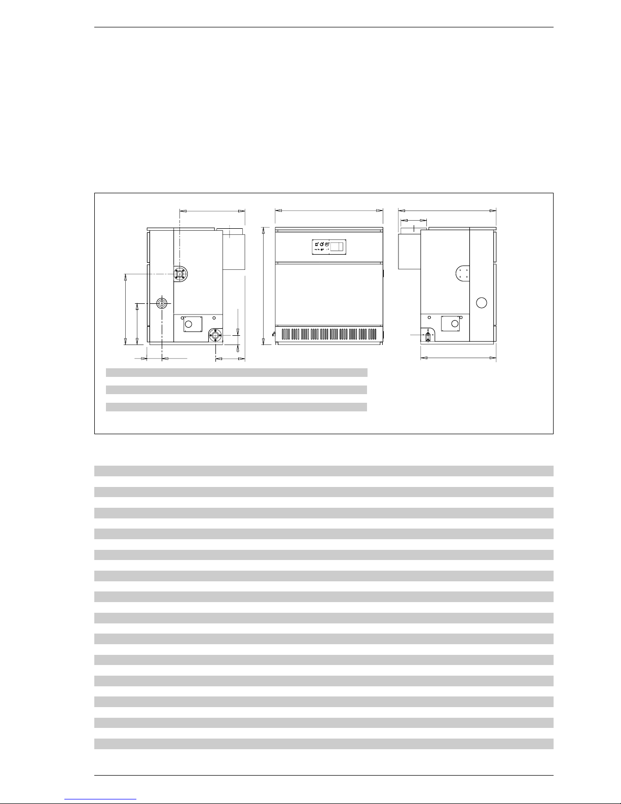
1.2 DIMENSIONS
129 151 172 194 215 237 258 279
L mm 810 920 1030 1145 1255 1370 1480 1580
P m m 1110 111 0 111 0 114 0 114 0 119 0 119 0 119 0
C mm 730 730 730 760 760 810 810 810
F mm 315 315 315 345 345 395 395 395
D ø mm 250 250 250 300 300 350 350 350
Fig. 1
R Return from heating system 2”
M Delivery to heating system 2”
G Gas 1
1
/
2
”
S Boiler drain 3/4”
1.3 TECHNICAL DATA
129 151 172 194 215 237 258 279
Thermal power kW 129,0 150,6 172,2 193,7 215,2 236,5 257,8 279,1
Thermal capacity kW 145,9 170,0 194,2 218,2 242,1 266,0 290,0 313,6
Electric power absorbed W 50 50 808080808080
Degree of electrical insulation IP 20 IP 20 IP 20 IP 20 IP 20 IP 20 IP 20 IP 20
Heating elements n° 7 8 9 10 11 12 13 14
Water content l 67,5 77,0 86,5 96,0 105,5 115,0 124,5 134,0
Max. operating pressure bar 5 5 5 5 5 5 5 5
Category II
2H3+ II2H3+ II2H3+ II2H3+ II2H3+ II2H3+ II2H3+ II2H3+
Type B11
B11 B11 B11 B11 B11 B11 B11
Maximum temperature °C 95 95 95 95 95 95 95 95
Main nozzles
Quantity n° 6 7 8 9 10 11 12 13
Methane gas ø mm 4,30 4,30 4,30 4,30 4,30 4,30 4,30 4,30
G30 - G31 ø mm 2,50 2,50 2,50 2,50 2,50 2,50 2,50 2,50
Gas rate of flow
Methane gas m
3
/h 15,44 17,99 20,55 23,10 25,63 28,16 30,70 33,20
Butane (G30) kg/h 11,50 13,41 15,32 17,21 19,10 20,98 22,88 24,74
Propane (G31) kg/h 11,32 13,19 15,07 16,93 18,79 20,64 22,50 24,34
Gas pressure at burners
Methane gas mbar 9,7 9,7 9,7 9,7 9,7 9,7 9,7 9,7
Butane (G30) mbar 28 28 28 28 28 28 28 28
Propane (G31) mbar 35 35 35 35 35 35 35 35
Gas supply pressure
Methane mbar 20 20 20 20 20 20 20 20
Butane (G30) mbar 30 30 30 30 30 30 30 30
Propane (G31) mbar 37 37 37 37 37 37 37 37
Weight kg 542 612 682 757 829 904 974 1044
59
1.4 SHIPPING
“RS Mk.II” thermal units are supplied
in three separate packs:
PACK N. 1
Cast iron body strapped onto pallet,
complete with:
– n° 2 flanges with 2” collar for hea-
ting system delivery and return
– n° 1 blind flange
– n° 1 flange with 3/4” connection for
drain cock
– n° 2 combustion chamber doors
with cast iron indicator door
– n° 2 sheaths for thermostats and
thermometer
– n° 1 water distributor located in the
boiler return manifold, supplied in
two different lengths:
L = 406 mm vers. “129÷194”
L = 851 mm vers. “215÷279”.
PACK N. 2
Wooden crate containing:
– flue gas chamber to be assembled
– cardboard box containing skirt
– main burners, one for each element
in the body minus one
– burner manifold
– plastic bag containing:
•
n° 13 tornillos M5 x 8 screws for
anchoring burners to manifold
•
n° 32 self-tapping 12E x 1/2”
screws for fastening various parts
of the flue gas chamber and skirt
•
n° 4 M8x30 screws with plate, flat
washer and M8 nut for anchoring
flue gas chamber to boiler body
•
n° 1 3/4” drain cock with cap.
PAQUETE n° 3
Cardboard box containing:
– Gas assembly, comprising:
•
main gas valve with coil unit
•
gas pressure switch
•
pressure intake
•
second gas solenoid valve
– Electric control panel, consisting of:
•
BRAHMA SM 191.1 control device
•
interference filter
•
ignition and detection electrodes
•
sockets for connection with control panel
•
anchoring screws
– Control panel consisting of:
•
two-step control thermostat
•
manually reset safety thermostat
•
thermometer
•
gas pressure indicator light
•
device shutdown indicator light
•
illuminated main switch
•
anchoring screws.
6
7
4
2
3
1
5
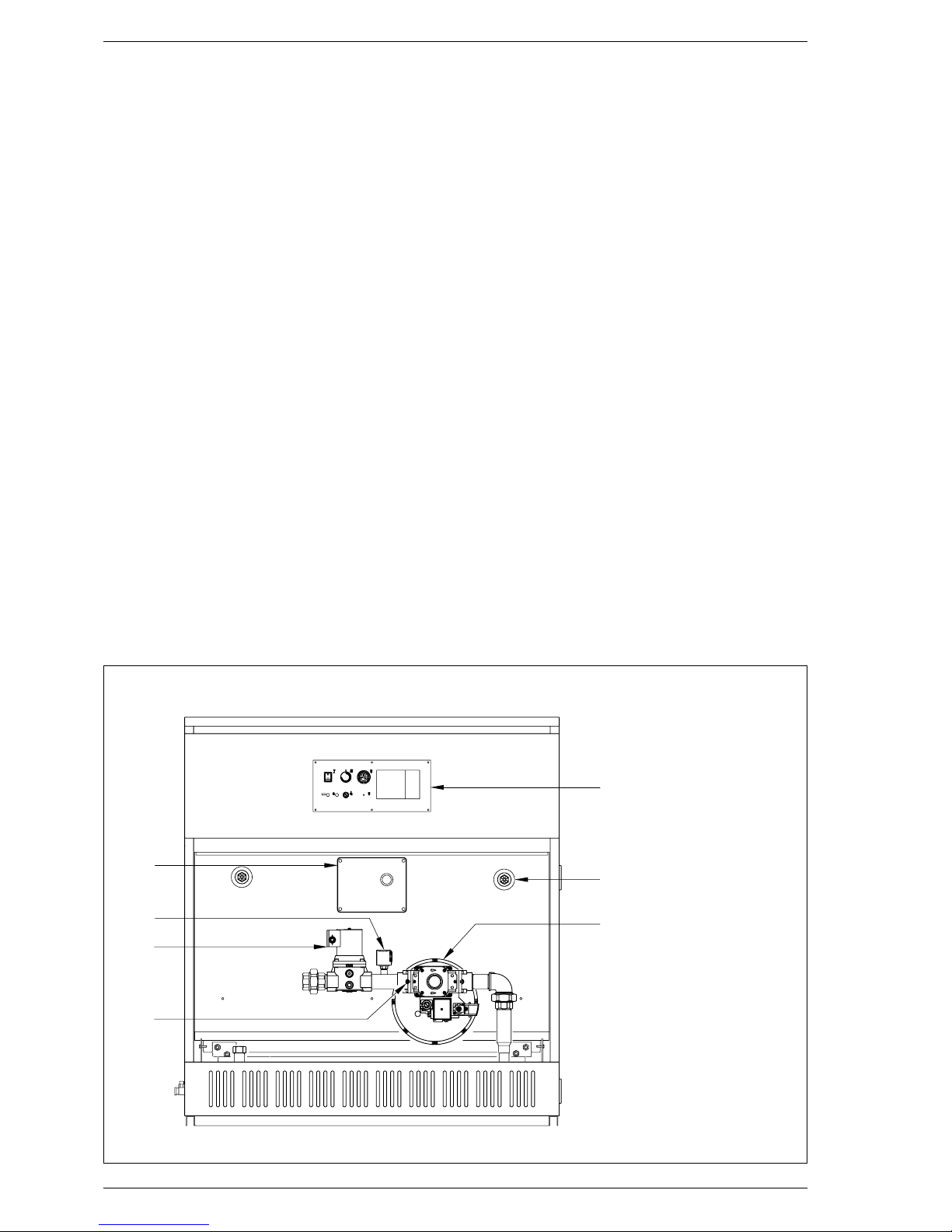
Fig. 2
1.5 FRONT INSIDE VIEW
KEY
1 Electrical control panel
2 Gas pressure switch
3 Second gas solenoid valve
4 Pressure intake
5 Control panel
6 Bulb housing sheath
7 Gas valve
 Loading...