

Page 1

Users, Installation & Servicing Instructions
Gas & Oil Fired Heaters
Direct Drive Fans
WARNING: THIS APPLIANCE MUST BE EARTHED
CE
TE Range Users, Installation & Servicing Instructions Issue 7.0 April 2014
The Powrmaster TE
Range
Page 2
Dear Customer
This is to certify that this heater is guaranteed for two years parts and one year
labour from the date of original commissioning. The heater must be
commissioned within 4 weeks of installation.
The heat exchanger, where fitted, is guaranteed (parts only) for a further eight
years, chargeable on a sliding scale basis, price relative to age.
To make a claim
In the first instance you must contact your appliance supplier, or installer and
provide:-
1. The appliance type and serial number.
2. The original commissioning documentation.
3. As much detail as possible on the fault.
Your supplier, or installer, will then contact Powrmatic to make a guarantee
claim on your behalf.
Conditions of Guarantee
1. The heater must have been installed by a competent recognised installer, and
in accordance with the manufacturers instructions, building regulations and
local regulations.
2. The heater has been professionally commissioned, within 4 weeks of
installation, and a copy of the Commissioning Sheet returned to Powrmatic.
3. The heater has been maintained on a yearly basis by a competent servicing
company.
4. The heater has been used in accordance with the manufacturers instructions.
5. The correct specification fuel has been used
6. No unauthorised repairs or modifications have been made.
7. Powrmatic ‘General Conditions of Sale’ have been observed.
8. Except for the obligation of Powrmatic Ltd to perform warranty repairs during
the guarantee period, Powrmatic will not be liable in respect of any claim for
direct or indirect consequential losses, including loss of profits or increased
costs arising from loss of use of the heater, or any event arising there from.
Exclusions
1. Gaskets and fan belts are not included in the guarantee
Important: This certificate must
be kept with the appliance
Certificate of Guarantee
Powrmatic Ltd, Hort Bridge, Ilminster, Somerset, TA19 9PS
tel: 01460 53535 fax: 01460 52341
web: www.powrmatic.co.uk e-mail: [email protected]
Installed
Date: ___________ Signed______________________________________ Installer
Commissioned
Date: ___________ Signed________________________ Commissioning Engineer
Failure to provide a copy of the Commissioning Sheet invalidates the heater warranty
Page 3
1
1. Checks before lighting the Air Heater
The following checks must be made before lighting the heater(s)
a) Ensure that the Auto/OFF switch on the heater panel is
switched to OFF
b) Ensure that the electrical supply to the heater is switched ON.
b) Check that the MC200 is calling for heat (See MC200 User
Instructions).
c) Check that any other controls are calling for heat and, if there
is a Summer/Winter mode, it is set to Winter.
d) Check that the overheat (Limit) thermostat has not operated.
2. Lighting the Air Heater
2.1 Gas-fired Heaters
1. Switch the Auto/OFF switch to Auto.
2) The main air fans will start. Note that, with the exception of
the TE21, the fan start may be staggered in which case the
second fan will not start until the first is running.
3) The burner air fan will run and after a pre purge period of
approximately 30 seconds the ignition spark will be generated.
TE21
The main gas valves will open and the main burner will be
established
TE 31, 41 & 61
The start gas valves will be opened and a start gas flame
established. When a start gas flame is established the main gas
valves will be energized and the start gas flame will expand to
main flame.
NOTE: If the main burner or a start gas flame fails to establish
the burner will go to lockout and the lockout indicator / reset
button on the burner control box will be illuminated. To restart
the burner push the lockout reset button. Additional, more easily
accessible, controls may be fitted that mimic the lockout indicator
and reset button functions.
If the unit will not light after four or five attempts then shut
down the unit and call in a service engineer.
2.2 Oil-fired Heaters
NOTE: If it is not possible to light the heater after 2/3 attempts
contact the local service company.
1. Switch on the electrical supply at the isolator.
2. The main air fans will start. Note that, with the exception of
the TE21, the fan start may be staggered in which case the
second fan will not start until the first is running.
3. The burner air fan will run and after a pre purge period of
approximately 30 seconds the ignition spark will be generated
and the oil valve opened. The main burner will then fire.
NOTE: If the burner fails to light it will go to lockout and the
lockout indicator / reset button on the burner control box will
be illuminated. To restart the burner push the lockout reset
button.
If the unit will not light after two or three attempts then shut
down the unit and call in a service engineer.
3. To Shut Down the Air Heater
3.1 For Short Periods:
Set the MC200 to OFF (See MC200 User Instructions).
3.2 For Long Periods:
Set the MC200 to OFF. Wait approximately 4-5 minutes
Users Instructions
for the residual heat in the heat exchanger to be dissipated
and then turn off the gas or oil supplies and electric supplies
to the heater.
4. Description of Operation
Important: All heaters must be controlled by the fitted controls
and not by use of the main switch in the electrical supply to the
heater.
TE heaters are designed for the main air fans to run continuously
thereby continually circulating the air in the building. The burner
start up sequence will commence when the MC200 calls for
heat. The burner air fan will run and after a pre purge period
the burner will light.
When the MC200 is satisfied the burner will be turned off. On
Hi/Lo and Modulating units the firing rate of the burner will be
adjusted automatically by the MC200 to suit the heat demand.
4.1 Summer / Winter Modes
Summer: The heater fans alone will run at the dictate of the
MC200 to provide air movement.
Winter: The heater will operate normally.
5. Fan and Limit Control
The fan and limit controls are mounted towards the top of the
side panels of the heat exchanger section .
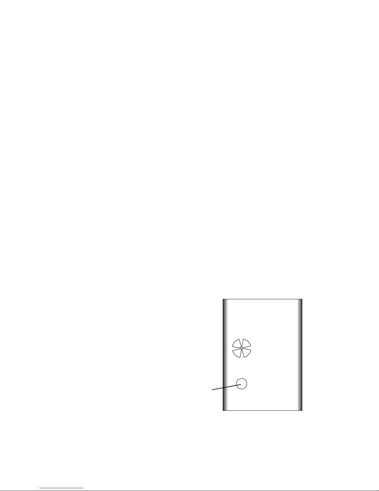
i) Main Air Fan MAN / Auto
When the white button (Refer to Figure 1 below) is pushed in
the fans will run continuously i.e not controlled by any external
controls e.g. Timeclock. When the white button is pulled out
the fans will start and stop automatically in conjunction with
the burner. See Section 4.
PUSH MAN
PULL AUTO
Honeywell
Fig 1. Fan Thermostat
White
Fan
button
ii) Limit Thermostat
This operates if high temperatures within the heater are detected,
the burners are turned off and a red indicator light on the front
of the heater is illuminated. The fault condition must be identified
and rectified and the thermostat manually reset. Remove the
black cover cap and press the exposed button to reset.
When the unit has cooled push the reset switch on the front of
Page 4

2
the heater to reset the limit thermostat interlock relay, the red
indicator light will go out and the unit is operational again.
Note: The limit thermostat(s) can only be reset once the unit
has cooled down.
Unless the cause of the fault condition is readily obvious, for
example a power cut whilst the heater was operating, a service
engineer should be contacted.
6. Maintenance
Regular servicing is essential to maintain efficient, reliable and
safe operation of the heater. Users are strongly recommended
to have the heater serviced at least annually and preferably at
the end of the heating season.
7. IMPORTANT
Free access must be maintained to and around the heater for
servicing purposes and the air supply to the heater must not be
restricted in any way. Combustible materials must not be stored
adjacent to the heater.
All Powrmatic heaters use gas, or oil, and electricity to power
them, they may also contain moving parts such as pulley belts.
It would be hazardous to tamper with or attempt to service unless
you are a competent person in the field of Gas and Electrical
work.
If you have any safety questions reference the servicing and
installation of any of our heaters please do not hesitate to contact
our head office for expert advice.
Your safety is paramount to us.
For gas fired heaters only:
If at any time a gas leak is suspected turn OFF the gas supply
- DO NOT USE A NAKED FLAME - and contact the local gas
undertaking immediately.
Gas Safety (Installation & Use) Regulations
It is law that all gas appliances are installed, adjusted and, if
necessary, converted by qualified persons* in accordance with
the latest edition of the above regulations. Failure to install
appliances correctly can lead to prosecution. It is in your own
interests and that of safety to ensure that the law is complied
with.
* An approved class of person listed on the gas register.
Page 5

1. INTRODUCTION
The Powrmatic Powrmaster TE range of gas fired forced draught,
closed flue, fanned circulation air heaters cover a heat output
range of 88 kW (300,000 Btu/h) to 806 kW (2,750,000 Btu/h)
and are intended primarily for heating commercial or industrial
premises.
Fuel Types
Gas fired units are certified for use on Natural Gas, Group H G20, Group L - G25 and Propane - G31.
Oil fired units are supplied as standard for use with 35sec fuel
and can be supplied for use with 28sec fuel as an option.
In accordance with guidelines from our burner supplier, Riello,
the burners fitted to Powrmatic oil-fired heaters are suitable for
fuels with a bio content of up to 10% only.
For fuels with a bio content of more than 10%, please consult
our Technical Department.
The heaters are for floor mounting, freeblowing applications
only.
TE heaters are also available as /EA variants which are suitable
for siting externally.
TE heaters have a double axial fan assembly fitted upstream of
the combustion chamber / heat exchanger assembly to circulate
the air being heated and the system design is for the fans to run
continuously thereby constantly circulating the air in the building.
Each fan is directly mounted onto the drive motor shaft and the
speed is governed by an inverter. Heaters are fitted as standard
with fully automatic monoblock On/Off forced draught gas
burners and monoblock gas control assemblies. High/Low or
3
CONTENTS
Section Title Page
1. Introduction 3
2. Technical Data 4
3. General Requirements 5
4. Installation 6
5. Commissioning & Testing 7
6. Servicing 8
7. Fault Finding 10
8. Short List of Parts 10
Appendix A 11
Tables Title Page
1. Dimensions (S.I. Units) 4
Figure Title Page
1. Direction of Fan Rotation 7
2. Main Control Panel 8
3. Taper Lock Bush Detail 8
4. Fan/Limit Thermostat 9
modulating burners are available as options.
Unless otherwise specified each heater is fitted with an MC200
electronic time and temperature control.
Each air heater must be connected to a closed flue system only.
Gas Safety (Installation & Use) Regulations
It is law that all gas appliances are installed, adjusted and, if
necessary, converted by qualified persons* in accordance with
the current issue of the above regulations. Failure to install
appliances correctly can lead to prosecution. It is in your own
interests and that of safety to ensure that the law is complied
with.
* An approved class of person listed on the gas register.
Page 6
F
E
D
C
G
A
ACCESS
DOOR
AIR
OUTLET
MODULE
B
R.H. SIDE VIEW.FRONT VIEW
CLEAN OUT DOOR
REAR VIEW
EXTENSION
MODULE
HEAT
EXCHANGER
MODULE
FAN
MODULE
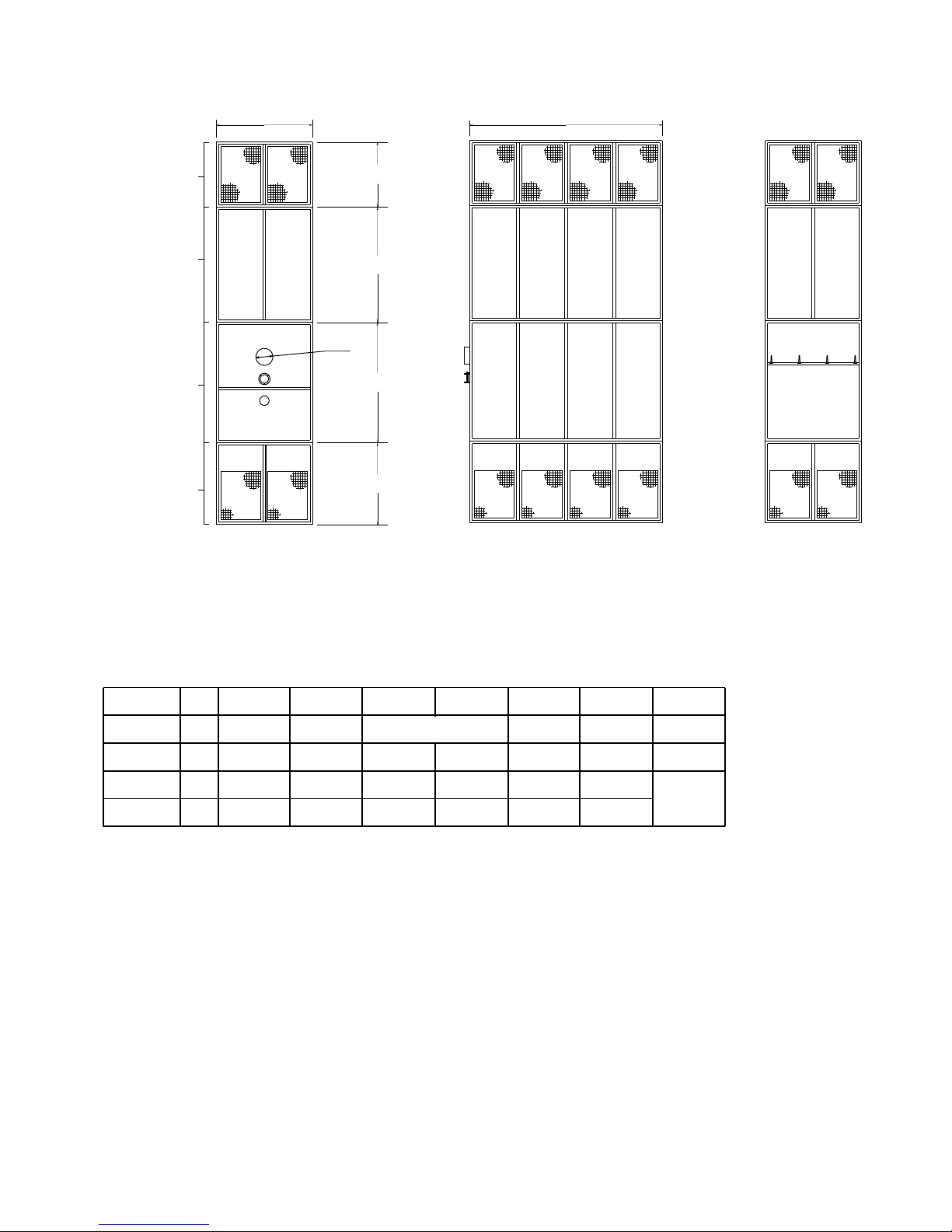
Note: TE 21 Fans and Combustion chamber/Heat exchanger are in one section
Table 1. Dimensions (S.I. Units)
TE21
TE31
TE41
TE61
Model A B C D E F G
mm
1010 1568 1873 in Total 1873 1416 150
mm
1162 2025 1213 1574 1778 660 200
mm
1518 2991 1213 1975 1899 959
300/350
mm
2026 4058 1721 2534 2432 1365
Specications, Burner Pressures and Electrical Data.
TE heaters are designed to suit individual applications. Please refer to the enclosed specification
sheet for the data specific to the heater supplied.
Note: The number of extension modules (0 - 2) depends on the application.
2 Technical Data
2.1 Dimensions
4
Page 7

3. General Requirements
3.1 Gas Fired Heaters
3.1.1 Related Documents
The installation of the air heater(s) must be in accordance with
the rules in force and the relevant requirements of the Gas Safety
Regulations, Building Regulations and the I.E.E. Regulations
for Electrical Installations.
It should also be in accordance with any relevant requirements
of the local gas region, local authority and fire authority and
the relevant recommendations of the following documents.
Institution of Gas Engineers & Managers
IGE/UP/1 (Ed.2) Strength and tightness testing and purging of
industrial and commercial gas installations.
IGE/UP/1A (Ed.2) Soundness testing and direct purging of
small low pressure industrial and commercial gas installations.
IGE/UP/1B (Ed.2) Tightness testing and direct purging of small
Natural Gas installations.
IGE/UP/2 Gas installation pipework, boosters and compressors
on industrial and commercial premises.
IGE/UP/4 (Ed.2) Commissioning of gas fired plant on industrial
and commercial premises.
IGE/UP/10 (Ed.3) Installation gas appliances in industrial and
commercial premises.
British Standards & Codes of Practice
BS 9999 Code of practice for fire safety in the design,
management and use of buildings
BS 6230: 2011 Installation of Gas Fired Forced Convection Air
Heaters for Commercial and Industrial Space Heating.
3.1.2 Service Pipes
The local gas undertaking should be consulted at the installation
planning stage in order to establish the availability of an adequate
supply of gas. An existing service pipe must not be used without
prior consultation with the local gas undertaking.
3.1.3 Meters
A gas meter is connected to the service pipe by the local gas
undertaking or a local gas undertaking contractor. An existing
meter should be checked, preferably by the gas undertaking, to
ensure that the meter is adequate to deal with the total rate of
gas supply required.
3.1.4 Installation Pipes
Installation pipes should be fitted in accordance with
IM/16:1988. Pipework from the meter to the air heater must be
of adequate size. Do not use pipes of a smaller size than the
inlet gas connection of the heater. The complete installation
must be tested for soundness as described in the above Code.
The complete installation must be tested for soundness as
described in BS 6230.
3.1.5 Boosted Supplies
Where it is necessary to employ a gas pressure booster the
controls must include a low pressure cut off switch at the booster
inlet. The local gas undertaking must be consulted before a gas
pressure booster is fitted.
3.2 Oil Fired Heaters
3.2.1 Related Documents
The installation of the air heater(s) must be in accordance with
the rules in force and the relevant requirements of the Building
Regulations and the I.E.E. Regulations for Electrical
Installations.
It should also be in accordance with any relevant requirements
of the local authority and fire authority and the relevant
recommendations of the following documents.
OFTEC Technical Book 3: Domestic & Commercial
requirements for oil storage and supply equipmement.
OFTEC Technical Book 4: Oil fired appliances & system
installation requirements.
OFTEC Easy Guides to non domestic oil feed pipes and oil
storage.
3.3 Air Supply
In buildings having a design air change rate of less than 0.5 /h,
and where TE heaters are to be installed in heated spaces having
a volume less than 4.7 m
3
/kW of total rated heat input grilles
shall be provide at low level as follows:The total minimum free area shall not be less than 270cm2 plus
2.25 cm2 per kilowatt in excess of 60 kW rated heat input.
The air vent(s) should have negligible resistance and must not
be sited in any position where it is likely to be easily blocked
or flooded or in any position adjacent to an extraction system
which is carrying flammable vapour.
3.4 Air Distribution System
Care should be taken to avoid impeding the air throw with
racking, partitions, plant or machinery etc.
A full and unobstructed return air path to the air heater(s) must
be provided.
Care must be taken to ensure that return-air intakes are kept
clear of sources of smells and fumes, and in special
circumstances where there is any possibility of pollution of the
air by dust, shavings etc., precautions must be taken by carefully
positioning return air intakes and by the provision of screens to
prevent contamination.
3.5 Electrical Supply
Wiring external to the air heater must be installed in accordance
with the I.E.E. Regulations for Electrical Installations and any
local regulations which apply. Wiring should be completed in
flexible conduit.
TE heaters require a 400V - 3N, 50Hz supply. The method of
connection to the main electricity supply must facilitate the
complete electrical isolation of the air heater(s) and the supply
should serve only the air heater(s).
The isolator must have a contact separation of at least 3mm in
all poles. The method of connection should be provided adjacent
to the air heater(s) in a readily accessible position.
See the accompanying wiring diagram for the heater electrical
connections.
5
Page 8

4. Installation of Air Heater(s)
4.1 General
Before installation, check that the local distribution
conditions, nature of gas and pressure (or oil type), and
adjustment of the appliance are compatible.
The air heater must be installed in accordance with the rules in
force and the relevant requirements of any fire regulations or
insurance company’s requirements appertaining to the area in
which the heater is located, particularly where special risks are
involved such as areas where petrol vehicles are housed, where
cellulose spraying is carried out, in wood working departments
etc.
The following minimum clearances for installation and servicing
must be observed.
To the front 1.0m
To the rear The depth of the heater
To the side 1.0m
Above the heater 1.0m
Any combustible material adjacent to the air heater and the flue
system must be so placed or shielded as to ensure that its
temperature does not exceed 65 °C.
IMPORTANT:
1.No air heater shall be installed where there is a foreseeable
risk of flammable particles, gases vapours or corrosion inducing
gases or vapours being drawn into either the heated air stream
or the air for combustion. In such cases installation may only
proceed if the air to be heated and the air for combustion are
ducted to the heater from an uncontaminated source preferably
outside the building. In certain situations where only airborne
particles are present it may suffice to fit filters on the air inlet
ducts of the heater. Advice in these instances may be obtained
from Powrmatic Ltd.
4.2 Location
The location chosen for the air heater must permit:
- the provision of a satisfactory flue system and an adequate air
supply.
- adequate space for servicing and air circulation around the air
heater.
The heater(s) must not be installed in conditions for which it is
not specifically designed e.g. where the atmosphere is corrosive
or salty, and they are not suitable for outdoor use unless the /EA
style is specified. /EA heaters must be installed on a plinth such
that there is a minimum distance of 0.5m between ground level
and the lowest point of any air inlet grilles.
Where the location of the air heater is such that it might suffer
external mechanical damage e.g. from overhead cranes, fork
lift trucks, it must be suitably protected.
TE heaters are for normal operation within an ambient
temperature range of -10 to 25°C.
4.3 Installation
TE heater installation may only be completed by Powrmatic
Ltd or their appointed representatives.The heaters must be
installed on a level noncombustible floor capable of supporting
the weight of the heater.
4.4
Combustion & Ventilation Air Supply
There shall be provision for a supply of air for combustion.
1) Installation in the heated space
In buildings with a design air change rate of 0.5 /h or greater,
additional natural or mechanical ventilation is not necessary.
In buildings not having a design air change rate of 0.5 /h the
following apply.
Natural Ventilation
Grilles having a free area of at least 2cm² per kW of rated heat
input shall be provided at low level i.e. below the level of the
heater flue connection.
Mechanical Ventilation
Must ensure that the space air change rate is at least 0.5/h, must
be of the ‘input’ type and interlocked to ensure the heaters cannot
work if the input system is not working.
2) Installation in plant rooms or enclosures
This type of installation is not applicable to TE heaters.
4.5 Flue System
A single wall tee piece is supplied with each heater and must
be fitted to the flue outlet socket on the heater. A closed chimney
system that conforms to the requirements of EN1856-1 and has
a designation appropriate to the application must be connected
to the outlet of this tee. The cross sectional area of the chimney
serving the appliance must be not less than the area of the flue
outlet of the air heater. The chimney must have a minimum
height, from the heater to the flue terminal, of 2m. Horizontal
runs of flue must be minimised but where they are
unavoidable the ratio of vertical to horizontal flue should be
not less than 3:1.
If necessary a single offset using two 45° bends can be included
to avoid obstructions. The minimum equivalent resistance of
the flue system should not be less than 0.0mb, the maximum
not greater than 0.5mb. Details of how to calculate the resistance
of the flue to be installed are given in Appendix A.
In order to minimise condensation the use of twin wall chimney
is recommended. With high efficiency heaters some condensation
in the chimney, particularly at the terminal, is unavoidable and
in addition there can also be rain water ingress. Use of a chimney
system having joint seals will minimise any leakage from the
flue system. The heater tee is provided with a collection tray
and the outlet from this should be run to a drainage point e.g.
a gully. The condensation pipe from the collection tray to the
disposal point should be of non-corrodible material of not less
than 22mm (3/4") size.
Facilities should be made for disconnecting the chimney pipe(s)
from the air heater(s) for inspection and servicing purposes.
The chimney outlet must be fitted with a terminal and where
the heater chimney is less than 200mm (8") in diameter an
approved terminal must be used.
The chimney must be supported independently of the air heater.
The chimney must terminate in a freely exposed position and
must be situated so as to prevent the products of combustion
entering any opening in a building in such concentration as to
be prejudicial to health or a nuisance..
The chimney terminal must be installed not less than:
- 300mm below an opening e.g. window, air brick etc.
- 200mm below eaves or gutter.
- 300mm from an internal or external corner.
- 1200mm from a surface facing the terminal.
- 1500mm vertically from another terminal on the same wall.
- 300mm horizontally from another terminal on the same wall.
- 2000mm from ground level.
4.6 Fuel Connection
4.6.1 Gas Connection (if applicable)
A servicing valve and downstream union must be fitted at the
inlet to the air heater gas controls assembly to facilitate servicing.
The gas supply to the air heater must be completed in solid
pipework and be adequately supported.
Warning
When completing the final gas connection to the heater do not
place undue strain on the gas pipework of the heater.
4.6.2 Oil Connection (if applicable)
Refer to the supplied burner installation instructions for details
regarding oil supply options.
6
Page 9
5.4 Lighting the Air Heater
5.4.1 Gas Controls Assembly - Soundness
Check
1. Ensure the gas service valve at the inlet to the gas controls
assembly is shut.
2. To prove soundness of the first main safety shut-off
valve and first start gas safety shut-off valve:a) Connect pressure gauge to the inlet pressure test point on
the main valve block or inlet pipework.
b) Open gas service valve and allow pressure to
stabilise before shutting it again. The valves are sound if
no pressure drop is observerved. If a pressure drop is
observed do not proceed until the fault has been rectified.
Remove pressure gauge and refit sealing screw in pressure
test point.
5.4.2 Sequence Check
1. Refer to the burner instructions supplied with the heater.
5.4.3 Final Adjustment
1. Remove the sealing screw from the pressure test point located
on the side of the gas inlet to the burner head and attach a
pressure gauge. Remove the sample point cover plug from the
outlet flue length and insert a CO
2
measuring instrument.
2. Remove the link in the main electrical control panel to isolate
the main gas valves.
3. Turn "ON" the main electricity supply and check that the
following sequence of events occur.
i) Burner fan runs.
ii) Ignition spark is heard.
iii) Start gas valves open.
iv) Start gas flame is established.
4. Check that the start gas pressure agrees with that in Tables
3.1 or 3.2. If necessary adjust the start gas pressure (See Data
Sheet).
4. Turn "OFF" the main electricity supply.
5. Reconnect the main gas valves electrical link.
6. Turn "ON" the main electrical supply and the burner will run
through its sequence untill main flame is established. Check
that the main burner gas pressure agrees with that on the
specification sheet. If necessary adjust the main burner gas
pressure (See Data Sheet and also Burner Manual for method).
7. Measure the CO2 content of the flue gases. If it is necessary
to adjust the combustion air ratio controls, to obtain a reading
of 9.0 - 9.5%, refer to the Burner Manual.
8. Remove pressure gauge, refit sealing screw in pressure test
point and flue sample point cover plug.
5.4.4 Final Soundness Test
1. After making final gas rate checks all joints on the gas controls
assembly must be tested for soundness using leak detection
fluid.
5.5 Controls
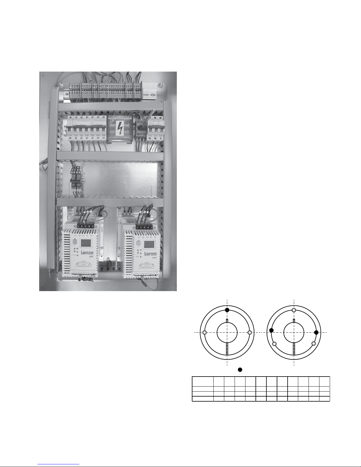
The general layout of the control panel is as shown opposite.
The MC200 controller is mounted in the access door of the
electrical panel.
5.5.1 Inverter Drives
This will have been set prior to the heater being despatched. A
data sheet of the settings used is included for future reference.
5.5.3 MC200
See the MC200 instructions seperately supplied.
5.6 Hand Over
Hand the Users Instructions to the user or purchaser for retention
and instruct in the efficient and safe operation of the air heater
and associated controls.
Adjust the automatic controls to those values required by the
User.
Finally, advise the user or purchaser that, for continued efficient
4.6 Electrical Connections
Wiring external to the air heater must be installed in accordance
with the I.E.E. Regulations for Electrical Installations and any
local regulations which apply. Wiring should be completed in
flexible conduit.
Heaters are for use with 230V, 1N, 50Hz or 400V, 3N, 50Hz
supplies (see heater data plate).
The method of connection to the main electricity supply must:-
- facilitate the complete electrical isolation of the heater(s) that
will prevent remote activation of the heater during servicing.
- be in a readily accessible position adjacent to the heater(s).
- serve only the heater(s).
- have a contact separation of at least 3mm in all poles. See the
wiring diagram for the heater electrical connections. All units
are fully pre-wired and only require final connections for the
incoming mains supply. The electrical supply must be run to a
point adjacent to the heater and be suitably terminated to provide
an isolation point that will prevent remote activation of the unit
during servicing. The heater electrical panel is located at the
front of the heater and cable entry points are provided in the
adjacent heater framework. Reference must be made to the
enclosed data sheet to ascertain the electrical loading of the air
heater(s) being installed so that cables of adequate cross-sectional
area to safely carry that load are used for the electrical
installation. The length of the conductors between the cord
anchorage and the terminals must be such that the current
carrying conductors become taut before the earth conductor if
the cable or cord slips out of the cord anchorage. All external
controls must be of an approved type.
See the wiring diagram accompanying these instructions.
5. Commissioning & Testing
Note: TE41 & TE61 - Turn key for electical panel access door
locks may be used to operate door elctrical interlock for
commissioning purposes .
5.1 Electrical Installation
Checks to ensure electrical safety must be carried out by a
qualified person.
5.2 Gas Installation
The whole of the gas installation, including the meter, should
be inspected and tested for soundness and purged in accordance
with the recommendations of the applicable IGE documents.
5.3 Fan Rotation
1. Whilst the main electrical supply is isolated and locked off
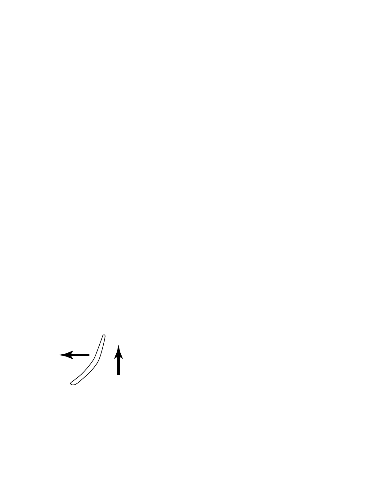
inspect the fan blades and ascertain the required direction of
rotation. See below.
1. Reinstate the electrical supply Turn the AUTO-OFF-MAN
switch to 'MAN'. Depending on the current state and setting of
the MC200 the mains fans may start immediately. If they do
not switch MC200 control (see MC200 manual supplied) to
‘Summer’ mode and then press the fan button on the front cover.
2. Ensure that the fan direction of rotation corresponds with the
direction of rotation arrow on the fan blades. If necessary turn
the AUTO-OFF-MAN switch to 'OFF', turn OFF the main
isolator and reverse the direction of rotation by interchanging
any two of the 3ph main supply leads at the terminal strip in the
electrical panel.
2. If appropriate reset the MC200 to Winter mode.
7
Direction of
blade rotation
Direction of air
ow
Fig 1 Direction of Fan Rotation
Page 10
8
and safe operation of the air heater, it is important that servicing
is carried out annually.
In the event that the premises are not yet occupied turn off the
gas and electricity supplies and leave instructional literature
adjacent to gas meter.
6. Servicing
WARNING: Always switch off and disconnect electricity supply
and close the gas service valve before carrying out any servicing
work or replacement of failed components. Access doors on TE
units are fitted with electrical interlocks however these alone
must not be relied upon to prevent equipment operation during
maintenace or servicing work.
6.1 General
Full maintenance should be undertaken not less than once per
year. After any servicing work has been completed or any
component replaced the air heater(s) must be fully commissioned
and tested for soundness as described in Section 6.
6.2 Burner Maintenance
1. Refer to the Burner Instructions supplied with the heater.
6.3 Heat Exchanger Cleaning
1. Disconnect the gas supply at the inlet to the gas controls
assembly.
2. Unplug the electrical connections from the heater electrical
panel to the buner.
3. Remove the nuts securing the burner to the heat exchanger
and remove the burner.
4. (TE 41 & 61 only) Remove the fixings of the second section
(from the floor) rear panel and hinge panel down to expose the
heat exchanger clean out access plate.
(TE21 only) Remove heater rear panel.
5. Remove the nuts securing the cleanout plate and remove.
6. Withdraw the heat exchanger baffles, if fitted.
7. Brush through heat exchanger tubes and remove loose material
using a vacuum cleaner.
8. Reassemble all components in reverse order. Inspect all gaskets
and replace if necessary.
6.4 Fan Assembly
WARNING Electrical supplies to the heater must be isolated
and locked OFF before proceeding.
1. Gain access to the fan section by removing the lower panels.
2. Inspect the fan blades to see that they are not damaged and
that there is no excessive build up of deposits that could give
rise to an imbalance. If necessary clean the fan blades using a
stiff brush and vacuum cleaner.
6.5 Replacement of Faulty Components
6.5.1. Burner Components
1. Refer to the burner supplement supplied with the heater.
6.5.2 Gas Controls Assembly
1. Refer to the burner supplement supplied with the heater.
6.5.3 Main Fan Motors
DANGER Electrical supplies to the heater must be isolated
and locked OFF before proceeding.
1. Remove fan assmbly from motor shaft. Note: On TE41 and
TE61 units the fans are fitted to the motor shafts by taper lock
bushes.
To remove a bush slacken all screws in it and remove (one or
two screws depending on the size of the bush). After oiling point
and thread of grub screws (bush size 1008 to 3030) or under
the head and thread of cap screws (bush size 3535 to 5050)
insert them into the jacking off hole(s) in the bush.
Tighten the screw(s) uniformly and alternatively until the bush
is loose in the hub and fan is free on the motor shaft. Remove
fan and bush.
Fig 2 Main Control Panel
Fig 3 Taper Lock Bush Detail
Inverter
Drive
Relays
1 & 2
Burner
MCB
ON/OFF
switch
Main Fan
MCB’s
Inverter
Drive
Bush
1008
1108
1310
1315
1210
1215
1610
1615
2012 251 7
3020
3030
3535 404 0 4 545 5050
Torque (Nm) 5.6 20 20 20 31 48 90 112 1 70 192 271
Screws 2 2 2 2 2 2 2 3 3 3 3
Screw Size (BSW) 1/4" 3/8" 3 /8" 3/8" 7/16" 1/2" 5/8" 1/2" 5/8" 3 /4" 7/8"
Jacking Point =
2. Disconnect the electrical connections from the motor and
remove the motor. Note: Providing the replacement motor is
identical it is recommended that bolts are fitted in the motor
mounting plate directly under the existing motor so that mounting
position is marked. The bolts will also support the weight of the
new motor whilst it is fitted.
Page 11
9
CAUTION
DO NOT ROT ATE - HOLD
DIAL WHEN SETTING POINTERS
2
0
4
0
6
0
8
0
1
0
0
1
2
0
F
A
N
L
I
M
I
T
O
F
F
O
N
O
F
F
C
°
Limit Setpoint
Adjustment
Fan Circuit
Limit Circuit
Fan ON
Override
Set Point Dial
Brass Link Location
Mechanical Limiter
Release Point
Mechanical limiter
Fan OFF Setpoint
Adjustment
Limit CircuitFan Circuit
Fan ON Setpoint
Adjustment
3. Fit new motor and reassemble in reverse order.
Refit the taper lock bush into the fan and line up the holes (half
threaded holes must line up with half straight holes). Lightly
oil the grub screw or cap screws and srew in but do not tighten.
Fit fan to shaft. Gradually tighten the grub/cap screws in
accordance with the torque schedule. Fill all holes with grease
to prevent dirt ingress. Recheck torque settings after half an
hours running.
6.5.4 Main Air Fan(s)
DANGER Electrical supplies to the heater must be isolated
and locked OFF before proceeding.
Should it be necessary to replace one or both of the fans
proceed as follows.
(TE41 & 61)
1. Remove fans as detailed in 6.5.3 above. On units with fans
having a high number of blades it may also be necessary to
remove one or two heat exchanger module side panels.
(TE21 & 31)
1. Remove one or two side panels to gain access to the top of
the fan shaft. Remove set screw securing fan assembly to the
motor shaft and remove fan.
2. Fit new fan(s) and reassemble in reverse order. Ensure the
loose key that prevents the fan assembly rotating on the fan
shaft is refitted.
6.5.5 Fan and Limit Thermostats
6.5.5.1 Honeywell L4064B
1. Release the single screw securing the fan and limit thermostat
cover and remove cover by pulling forward.
2. Release wiring from screw terminals.
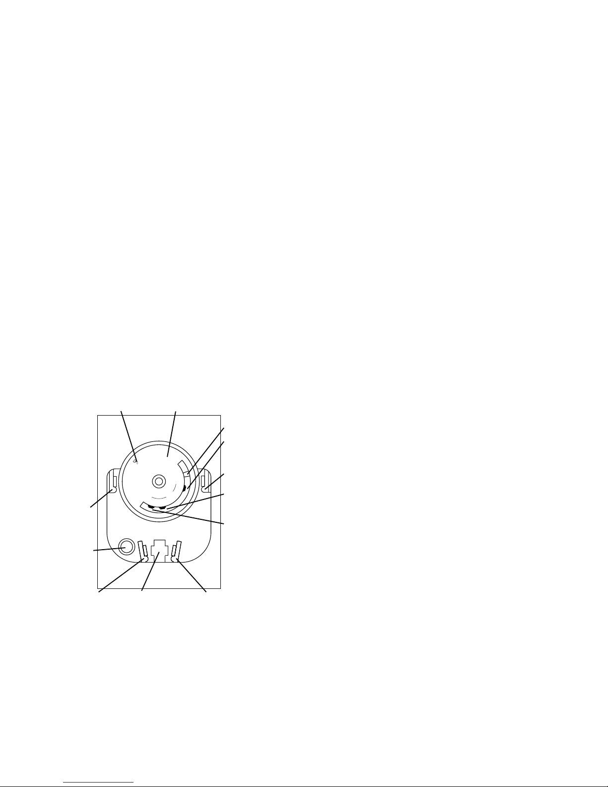
Figure 4 Fan/Limit Thermostat
3. Remove the 2 screws securing the thermostat to the heater
panel and withdraw thermostat and sensor.
4. Reassemble new unit in reverse order refering to the heater
wiring diagram to ensure correct wiring location.
Important: A replacement fan/limit thermostat will have a brass
link between the bottom fan terminal and the bottom limit
terminal (situated in the slot between the two terminals). This
MUST be removed, by breaking the link off using a pair of thin
nose pliers, before the replacement thermostat is installed.
5. Ensure that the fan and limit settings are as follows: Fan ON - 40°C, Fan OFF - 20°C
Limit 60°C
Note: The new L4064B may be supplied with the limit
temperature mechanically limited to less than the setting required.
To release the mechanical limit push a pointed object into the
small hole at the top of the dial. At the same time prevent the
dial from rotating and push the limit temperature adjuster around
to the required setting.
6.5.5.2 High Limit Thermostat
TE41 & 61
1. Release the two screws securing the limit thermostat housing
cover and remove cover by pulling forward.
2. Release the thermostat from the front cover, two screws
3. Pull off wiring connectors from under the thermostat.
4.Remove a central side panel from the heater exchanger section
to gain access to the heat exchanger and release the thermostat
sensing phial from its holder on top of the heat exchanger and
withdraw thermostat and phial.
5. Reassemble new unit in reverse order refering to the heater
wiring diagram to ensure correct wiring location.
6. Ensure that the setting is as follows: Limit 100°C
TE21 & 31
1. Release the two screws securing the limit thermostat housing
cover and remove cover by pulling forward.
2. Release the thermostat from the front cover, two screws
3. Pull off wiring connectors from under the thermostat.
4.Remove heater side panels and release the thermostat sensing
phial from its holder on the fan shroud and withdraw thermostat
and phial.
5. Reassemble new unit in reverse order refering to the heater
wiring diagram to ensure correct wiring location.
6. Ensure that the setting is as follows: Limit 50°C
6.5.5.3 Fan Protection Thermostat
TE 21 & TE31
1. To replace the thermocouple remove the side panels on
on side of the heater. Release the tip of the thermocouple
from its holder and disconecct the other end from the relay
base. Renew using a Type K thermocouple only.
Page 12

10
Fault
Main burner will not light
Main burner lights, but
goes out before main fan
comes on.
Main fan fails to run
Cause
Electrical
Electrical
Electrical
Action
1. Check electrical and fuel supplies are ON.
2. Check controls are ON or calling for heat.
1. Unit goes out on high limit a. Check limit thermostat setting - See Section 7.5.5.
b. Faulty limit thermostat - change.
3. Inverter code 0C6, motor overloaded. - Check running amps. See
specification sheet.
1. Fan motor (or capacitor - 1ph only) failed - replace.
2. Fan thermostat faulty - replace.
3. Inverter failed - replace
8. Short List of Parts
Refer to the burner supplement supplied with the heater.
Refer to Powrmatic Ltd for the details of other parts quoting the serial number of the heater.
7. Fault Finding
Refer also to the burner supplement supplied with the heater
Page 13

Appendix A
Calculation Of Flue System Equivalent Resistance
The pressure resistance of the flue system (Pr) = 1.5 * [(PFF*H/D+SRF)Qm/Wm2] (pa)
Where H = Effective flue height in m
D = Internal Diameter of flue in m
PRF (Pipe Friction Factor) = 0.118*(0.21147/D0.4)
Where D = Internal Diameter of flue in m
SRF (Sum of individual resistance factors)
Typical resistance factors for individual components are as follows
Segmented 90° bend 0.5
45° Elbow 0.4
Cowl 1.0
Qm (Mean Density of the column of exhaust gas in kg/m3) = 97000/(300*Tm)
Where the mean temperature of the column of exhaust gas (Tm) = 288+((Te-TL)/0.2)*(0.18)
Where Te is the exhaust gas temperature in °C
TL is the external air temperature in °C
Wm (Mean exhaust gas velocity in m/s = M/(A*Qm)
Where A is the cross sectional area of the flue in m2
M is the exhaust gas mass flow in kg/s which for this heater is
______________
Every effort is made to ensure accuracy at time of going to press. However as part of our policy of continual product improvement, we reserve the right to alter specifications without prior notice.
HEATING DIVISION
Hort Bridge
Ilminster, Somerset TA19 9PS
Tel: 01460 53535 Fax: 01460 52341
BSI Registered Firm
FM 414
Ind. & Comm. Air Heaters;
Air Moving Equipment;
Natural, Smoke & Heat
Ventilators;
Powered Supply & Extract
Fans & Systems.
ISO 9001
Page 14

Every effort is made to ensure accuracy at time of going to press. However as part of our policy of continual product improvement, we reserve the right to alter specifications without prior notice.
HEATING DIVISION
Hort Bridge
Ilminster, Somerset TA19 9PS
Tel: 01460 53535 Fax: 01460 52341
BSI Registered Firm
FM 414
Ind. & Comm. Air Heaters;
Air Moving Equipment;
Natural, Smoke & Heat
Ventilators;
Powered Supply & Extract
Fans & Systems.
ISO 9001
 Loading...