

OPERATOR’S MANUAL & PARTS LIST
PAS17BA
(Base Unit Only)
PAS17BA-BC
(with Batteries and Charger)
WARNING: OPERATOR MUST READ AND UNDERSTAND THIS MANUAL
COMPLETELY BEFORE OPERATING THIS EQUIPMENT.
©
Tacony Corporation, All rights reserved
Save These Instructions
PAS17BA-BA-BC-Man 9/2017

TABLE OF CONTENTS
Warranty .......................................................................................................... 3
Safety Instructions .......................................................................................... 3
Machine Set-Up .............................................................................................. 4
Machine Specication ..................................................................................... 4
Daily Operation and Maintenance .................................................................. 5
How to Install Batteries .............................................................................. 5
How to Charge the Batteries ...................................................................... 5
How to Install the Squeegee ....................................................................... 5
How to Install Pad Holder and Brush ......................................................... 5
How to Fill the Solution Tank .................................................................... 5
How To Operate The Machine ........................................................................ 6
How to Turn the Vacuum Motor On and Off ............................................. 6
How to Lower/Raise the Brush/Pad ........................................................... 6
How to Lower/Raise the Squeegee ............................................................ 6
How to Set the Solution Flow .................................................................... 6
What to Do When You’re Operating The Machine ........................................ 7
Vacuuming Up Solution ............................................................................. 7
How to Control Excess Foam in the Recovery Tank ................................. 7
How to Empty the Recovery Tank ............................................................. 7
Maintenance .................................................................................................... 7
Daily ........................................................................................................... 7
Weekly ........................................................................................................ 7
Monthly ...................................................................................................... 7
Replacement Parts: .......................................................................................... 8
Brush .......................................................................................................... 8
Clutch Plate ................................................................................................ 8
Battery ........................................................................................................ 8
Charger ....................................................................................................... 8
Parts List: ........................................................................................................ 8
Assembly List:............................................................................................ 8
Chassis Assembly ....................................................................................... 9
Valve Assembly .......................................................................................... 9
Brush Assembly........................................................................................ 10
Control Panel Assembly ........................................................................... 10
Vacuum Motor Assembly ..........................................................................11
Float Assembly ..........................................................................................11
Lift Assembly ........................................................................................... 12
Squeegee Assembly .................................................................................. 12
Squeegee Lift Assembly ........................................................................... 13
Vacuum Hose Assembly ........................................................................... 14
Recovery Drain Hose Assembly .............................................................. 14
Solution Drain Hose Assembly ................................................................ 14
Troubleshooting ............................................................................................ 15
2

WARRANTY
The manufacturer warrants to the original purchaser that products manufactured are free from
defects of workmanship and material, provided such goods are installed, operated and maintained in
accordance with written manuals or other instructions for a period of 5 years from date of purchase
on housings, tanks and frame, 2 years motors, 1 year parts and workmanship (excludes normal wear
items). In case you as our customer, meet any trouble with your machine, contact your Powr-Flite
representative who will be happy to be of service to you and will take care of the warranty settlement.
NOTE: Alterations and changes made to the machine without written approval of the manufacturer
and use of unapproved spare parts will not be covered by warranty.
SAFETY INSTRUCTIONS
FOR COMMERCIAL USE
READ ALL INSTRUCTIONS BEFORE USING THIS MACHINE
• Use indoors only. Do not expose to rain.
• Do not allow it to be used as a toy. Use caution when operating near children.
• Use only as described in this manual.
• Use only manufacturer’s recommended accessories.
• Charge batteries in a ventilated room. Gases given off during charging could ignite in a conned space.
To avoid an explosion, top cover should be open and battery caps installed when charging.
• Disconnect all positive and negative battery terminals before attempting any adjustment or maintenance.
Brush drive and vacuum motors and components can cause injury if accidentally started.
• Battery acid can cause injury to the eyes or skin. Wear protective goggles, gloves and clothing BEFORE
lling or charging batteries.
• If charger is not working properly, (due to it being dropped, damaged, left outdoors or exposed to water)
return it to a Powr-Flite Service Center.
• Do not handle the plug or machine with wet hands.
• Do not put any objects into openings. Keep the openings unblocked
• Keep it away from dust, lint, hair and anything that may reduce air ow.
• Keep hair, loose clothing, ngers and all body parts away from openings and moving parts.
• Make sure the main power switch is OFF before removing or installing pads or brushes.
• Never operate the machine if you are tired or under the inuence of drugs and/or alcohol.
• Always operate the machine while standing behind it.
• Use care when working on electrical terminals. Short circuits can cause burns.
• Do not store the machine on inclines.
3
19 20
1
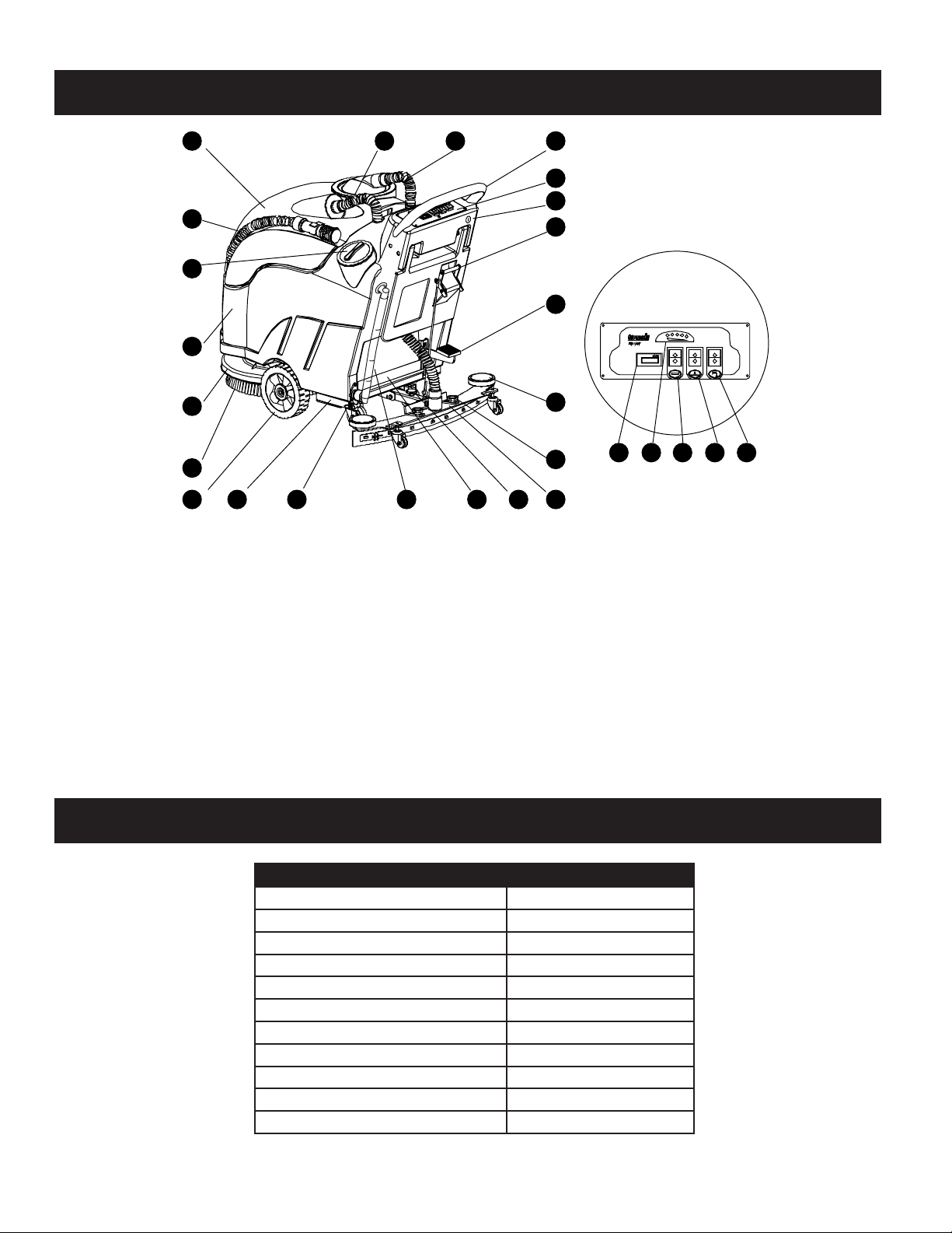
Machine Set-Up
18
17
16
2
22
3
4
15
14
13
1. Handle Bar
2. Control Panel
a .....Hour Meter
b ....Battery Condition Indicator
c .....Brush Motor Switch
d ....Vacuum Motor Switch
e. ....Solution Switch
3. Squeegee Release Handle
4. Brush Lift Pedal
5. Wheel, Bump
6. Squeegee Mount Knob
7. Squeegee
8. Squeegee Tilt Knob
9. Water level sight tube
Machine Specication
5
6
a21b c
d
789 101112
10. Battery
11. Valve, Solution Volume Control
12. Frame
13. Wheel
14. Brush/Pad Holder
15. Strap, Splash Guard
16. Solution Tank
17. Solution Fill Hole
18. Recovery Drain Hose
19. Recovery Tank
20. Squeegee Hose
21. Vacuum Hose
22. Key Switch
e
4
PAS17BA+ AUTOMATIC SCRUBBER
Brush Width 17"
Squeegee Width 30"
Solution Tank 11 gal.
Recovery Tank 12 gal.
Brush Rotation 200 rpm
Productivity Rate 12,700 ft
Voltage 24 V
Vacuum Motor Power .75 HP
Brush Motor Power .75 HP
Weight (without Batteries) 210 lbs.
Length x Width x Height 49" x 26" x 44"
2
per hour
Daily Operation and Maintenance
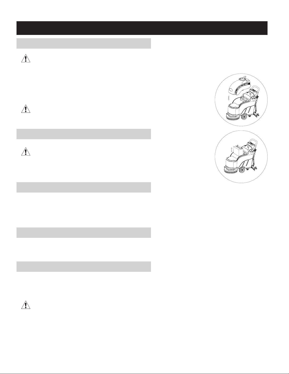
How to Install Batteries
Caution: Batteries are heavy.
Install (2) 12-volt deep cycle batteries. New Batteries should be given a full charge before rst use.
1. Unplug the hoses (20, 21) from the recovery tank (19).
2. Make sure the recovery tank is empty then lift it up.
3. Place batteries on the tray. Use the bracket to secure them. Position them correctly.
4. Connect all the cable terminals.
Caution: Make sure you connect RED (+) cable terminals to positive (+) posts and BLACK
(-) cable terminals to negative (-) posts. Machine will not operate if not connected properly.
Failure to do so will result in damage to batteries and possible explosion.
Spray each post with a protective lubricant. Place battery terminal protectors over all posts.
How to Charge the Batteries
Caution: Only use a battery charger designed for the machine. Failure to do so can result
in damage to the batteries.
Remove the recovery tank from machine and disconnect anderson plug from the control planel.
Next connect the charging plug to the anderson plug connected to the battery terminal. Plug the
other charger plug to wall outlet. The charger will automatically begin to charge the batteries.
How to Install the Squeegee
1. Put squeegee Release Handle (3) in the UP and locked position.
2. Position the squeegee blade assembly on the swing arm. Make sure the guide wheels face
the rear of the squeegee.
3. Hand tighten the 2 thumb screw (6).
4. Place the solution recovery hose (20) over the nozzle. Make sure it ts tight.
How to Install Pad Holder and Brush
1. Raise the brush pad by stepping on Brush Lift Pedal (4) at the rear of the machine.
2. With the pad holder/brush (14) in lifted position, insert it into the plate underneath by
turning it counter-clockwise until it locks.
How to Fill the Solution Tank
1. Open the solution ll cover (17).
2. Fill the tank (16) with the desired level of clean water.
3. Add cleaning chemical.
Do not overll.
5

How To Operate The Machine
1. To turn the power on, turn the key switch (22). The power/battery indicator (b)
will light up.
2. Check the battery capacity to see if it is full – all indicators are lit up when
batteries are fully charged.
3. To turn on the brush motor, vacuum motor and the solution ow, press the
switches (c,d,e).
Turn off the brush motor when the brush deck is in the up position.
How to Turn the Vacuum Motor On and Off
1. Push the top half of the right switch (d) down. This turns the vacuum motor on.
2. To turn the vacuum motor off, push the lower half of the right switch (d) down.
How to Lower/Raise the Brush/Pad
1. To raise the brush pad, step down on the Brush Lift Pedal (4) until it locks in place.
2. To lower the brush pad, slightly step on the Brush Lift Pedal (4) to unlock it, and raise it up
slowly.
How to Lower/Raise the Squeegee
1. Pull the handle (3) down to lower the squeegee.
2. Lift the handle (3) up to raise the squeegee.
Vacuum Motor BrushMotor Water Flow
How to Set the Solution Flow
Adjust the water ow based on the oor conditions. Turn the adjustment knob (11) to control the water ow. Position 1 shows
the closed position. Position 2 shows the maximum water ow position.
6

What to Do When You’re Operating The Machine
Vacuuming Up Solution
1. Make sure the squeegee is in the down position.
2. As the machine moves forward and solution is dispensed, the squeegee will vacuum it up into the recovery tank.
3. If necessary adjust squeegee pressure by turning knob (8).
If solution is missed, reduce the amount of solution ow, raise the squeegee and pull the machine back over the missed area.
Lower the squeegee and move the machine forward to pick up any remaining solution.
How to Control Excess Foam in the Recovery Tank
Watch the liquid as it accumulates in the recovery tank. If you notice excess foaming, stop the machine. Add the recommended
amount of chemical defoamer in the recovery tank (19).
How to Empty the Recovery Tank
Open the Recovery Drain Hose (18) to empty the Recovery Tank (19).
Maintenance
Daily
1. Empty and rinse the recovery tank with clean water. Leave the tank cover (21) open on top to air dry.
2. Remove the squeegee assembly, rinse and wipe clean. Check the squeegee inlet for clogs or debris.
3. Clean and wipe the tops of batteries with an ammoniated window cleaner.
4. Fill each battery cell with DISTILLED water as needed. DO NOT use tap water.
5. Charge the batteries as described in this manual.
Weekly
Never test the strength of the battery unless it is fully charged and cool.
Check the battery cells with a hydrometer.
Monthly
1. Lubricate brush and squeegee lift mechanisms with light oil.
2. Check for wear or damage of clutch plate, brushes, pads or squeegee blades.
3. Clean all battery terminals.
4. Check all electrical connections and tighten if any are loose.
5. Clean the entire machine with all purpose cleaner.
7

Replacement Parts
PART DESCRIPTION
SF616 Poly Scrub Brush (Optional)
PFLG16 Lite Grit Scrub Brush (Optional)
PFMG16 Medium Grit Scrub Brush (Optional)
PFHG16 Heavy Grit Scrub Brush (Optional)
UP2P Clutch Plate (must be used with all scrub brushes)
PAS17PD 17” Pad Driver
B27TMX 12 Volt Battery (2 Required)
EC24 24 Volt, 20 Amp Charger
Parts List
Brush
Clutch Plate
Pad Holder
Battery
Charger
Assembly List
REF. PART NO. DESCRIPTION
1 See pg. 9 Chassis Assembly
2 See pg. 10 Brush Motor Assembly
3 See pg. 11 Vacuum Motor Assembly
4 33647 Solution Tank
5 33648 Recovery Tank
6 See pg. 11 Float Assembly
7 See pg. 12 Lift Assembly
8 See pg. 13 Squeegee Lift Assembly
9 See pg. 12 Squeegee Assembly
10 See pg. 10 Control Panel Assembly
11 33654 Cap
12 See pg. 9 Valve Filter Assembly
13 See pg. 14 Vacuum Hose Assembly
14 See pg. 14 Water Level Sight Tube
15 See pg. 14 Recovery Tank Hose Assembly
16 33659 Battery Holding Plate
17 33660 Hose Clip
18 B27TMX 12 V Battery (2 Required – see
“Replacement Parts”)
8

Chassis Assembly
Valve Assembly
REF. PART NO. DESCRIPTION QTY
1 33668 Chassis 1
2 33669 Bracket 1
3 33670 Screw 3
4 33671 Nut 8
5 33672 Castor 2
6 33673 Screw 4
7 33674 Washer 4
8 33675 Bearing 4
9 33676 Wheel 2
10 33677 Spacer 2
11 33678 Cap 2
12 33679 Bolt 2
13 33680 Screw 8
14 33681 Spring Washer 8
REF. PART NO. DESCRIPTION QTY.
1 33808 Hose 1
2 33809 Cover 1
3 33810 O-Ring 1
4 33811 Spring 1
5 33812 Filter 1
6 33813 Washer 1
7 33814 Screw 1
8 33815 Screw 3
9 33816 Filter Support 1
10 33817 O-Ring 1
11 33818 Nut 4
12 33819 Filter Bracket 1
13 33820 Hose 1
REF. PARTNO. DESCRIPTION QTY.
14 33821 Nut 2
15 33822 Screw 2
16 33823 Bracket 1
17 33824 Bolt 2
18 33825 Solution Solinoid
1
Valve
19 33826 Hose 1
20 33827 Nut 3
21 33828 Screw 4
Screw 1
Solution Valve 1
22 33101
O-Ring 1
O-Ring 1
Solution Control
1
Lever
9

Brush Assembly
REF. PART NO. DESCRIPTION QTY
1 33682 Brush Motor 1
2 33683 Key 1
3 33684 Bolt 4
4 33685 Cover 1
5 33686 Skirt 1
6 33687 Strap 1
7 33688 Bracket 1
8 33689 Water Drain Out 1
9 33690 Washer 1
10 33691 Bolt 1
Brush
11 SF616
12 33692 Brush Driver 1
13 33693 Screw 3
14 33694 Bolt 5
15 33695 Nut 4
16 33696 Spacer 1
17 33697 Nut 1
18 33698 Liner 1
19 33699 Screw 3
20 33700 Side Pulley 1
21 33701 Bolt 1
22 33702 Lid 1
(See “Replacement
Parts”)
1
Control Panel Assembly
REF. PART NO. DESCRIPTION QTY
1 33797 Control Box 1
2 33798 Nut 6
3 33799 Key Switch Assembly 1
REF. PART NO. DESCRIPTION QTY
4 33800 Bolt 6
5 33801 Control Panel 1
6 33802 Screw 4
10

Vacuum Motor
Assembly
REF. PART NO. DESCRIPTION QTY
9 33711 Muffler 1
10 33712 Sponge 2
11 33713 Core 1
12 33714 Screw 2
13 33715 Bolt 2
14 33716 Spacer Ring 1
15 33717 Bolt 4
16 33718 Bolt 4
Float Assembly
REF. PART NO. DESCRIPTION QTY
1 33719 Top Lid 1
2 33720 Seal 1
3 33721 Fitting Mesh 1
4 33722 Screw 3
5 33723 Filter 1
6 33724 Gasket 1
7 33725 Cover 1
8 33726 Float 1
9 33727 Bucket 1
10 33728 Screw 1
11 33729 Hose 1
12 33730 Hose Liner 1
13 33731 Sleeve 1
REF. PART NO. DESCRIPTION QTY
1 33703 Elbow 2
2 33704 Bracket 1
3 33705 Connector 4
4 33706 Gasket 1
5 33707 Vacuum Motor 1
6 33708 Nut 4
7 33709 Hose 1
8 33710 Sleeve 1
11

Lift Assembly
REF. PART NO. DESCRIPTION QTY
1 33732 Lift 1
2 33733 Washer 2
3 33734 Pin 2
4 33735
5 33736 Washer 2
6 33737 Screw 2
7 33738 Nut 2
8 33739 Pedal Cover 1
9 33740 Pedal 1
10 33741 Spring Pin 1
11 33742 Bolt 2
12 33743 Pin Shaft 1
13 33744 Washer 1
14 33745 Cotter Pin 1
15 33746 Arm 1
16 33747 Nut 2
17 33748 Pin Shaft 1
Eccentricity
Bushing
2
Squeegee Assembly
REF. PART NO. DESCRIPTION QTY
1 33780 Squeegee Assembly 1
2 33781 Squeegee Blade Front 1
3 33782 Squeegee Blade Strap Front 1
4 33783 Butterfly Nut 6
5 33784 Nut 2
6 33785 Screw 3
7 33786 Squeegee Guide Wheel 2
8 33787 Bolt 2
9 33788 Lid 2
REF. PART NO. DESCRIPTION QTY
10 33789 Butterfly Nut 2
11 33790 Knob 2
12 33791 Nut 1
13 33792 Squeegee Blade Strap Rear 1
14 33793 Bolt 1
15 33794 Strap Rear 1
16 33795 Squeegee Blade Rear 1
17 33796 Castor 2
12

Squeegee Lift Assembly
REF. PART NO. DESCRIPTION QTY
1 33749 Bolt 1
2 33750 Plate Right 1
3 33751 Pipe 1
4 33752 Handle 1
5 33753 Plate Left 1
6 33754 Screw 2
7 33755 Washer 1
8 33756 Screw 1
9 33757 Nut 1
10 33758 Liner 3
11 33759 Rope Assembly 1
12 33760 Hang Ring 1
13 33761 Nut 1
14 33762 Balance Frame 1
15 33763 Shaft 1
16 33764 Cotter Pin 1
17 33765 Washer 1
18 33766 Pin Shaft 1
19 33767 Adjust Nut 1
20 33768 Supporting Arm 1
21 33769 Supporting Arm 1
22 33770 Nut 1
23 33771 Washer 1
24 33772 Spring 1
25 33773 Bolt Shaft 1
26 33774 Cotter Pin 1
27 33775 Washer 1
28 33776 Pin Shaft 1
29 33777 Adjust Bolt 1
30 33778 Adjuster 1
31 33779 Spring Pin 1
13

Vacuum Hose Assembly
Recovery Drain Hose Assembly
1
Water Level Sight Tube
REF. PART NO. DESCRIPTION QTY.
Vacuum Hose Assembly
1 33829 Sleeve 1
2 33830 Hose 1
3 33831 Sleeve 1
4 33832 O-Ring 2
Recovery Drain Hose Assembly
1 PAS700 Drain Out Plug 1
2 33834 Screw 2
3 33835 Hose Clamp 2
6 33838 Clamp 1
7 33839 Screw 3
8 33840 Base Joint 1
9 33841 Gasket 1
10 33842 Screw 2
Water Level Sight Tube
1 XD18W-14-00 Sight hose assembly 1
2 33834 Screws 3
14

Troubleshooting
Problem: Possible Cause:
Solution is not being
picked up
Squeegee is leaving
streaks
Solution is not feeding or
turning off properly
Batteries are not
holding a charge
Floors are not being
scrubbed, stripped or
buffed properly
Vacuum motor is not running
Water lter is clogged
Recovery tank is full
Squeegee or vacuum hose is clogged, broken or disconnected
Bad seal at tank cover, vacuum motor or squeegee
Worn or misaligned squeegee blades.
Incorrect squeegee pressure.
Squeegee swing arm mechanism not functioning properly
Debris is on blade
Blades are torn or damaged
Floors not properly swept before cleaning
Clogging of hose or valve
Batteries need to be replaced
High current draw from high brush pressure
Charger needs servicing
Battery is run down
Brush motor not working
Excessive pad or brush wear
Going too fast over dirty spots
Inadequate solution feed
Inadequate cleaning procedure
15

PAS17BA-BA-BC-Man 9/2017
16
A Tacony Company
3101 Wichita Court • Ft. Worth, TX 76140-1755
1-800-880-2913 • Fax: 1-817-551-0719 • www.Powr-Flite.com
 Loading...