


Index
1. Notes on thi s manual ............................................................. 2
1.1 Scope of Validation ............................................................. 2
1.2 Symbols Used ..................................................................... 2
1.3 Technical Competence ........................................................ 3
1.4 Target Group ....................................................................... 4
2. Preparation ........................................................................... 5
2.1 Safety Instructions ............................................................. 5
2.2 EC Directives ....................................................................... 7
2.3 Use condition ...................................................................... 8
2.4 Selection of fuse and cables ................................................ 9
2.5 Capacitor discharge .......................................................... 10
2.6 PE connection and leakage current ................................... 11
2.7 Safety Check ..................................................................... 12
2.8 Explanations of Symbols on Inverter ................................ 13
3. Product Information ............................................................ 16
3.1 Overview .......................................................................... 16
3.2 Major Characteristics ........................................................ 16
3.3 Product Identification ....................................................... 17
3.4 Quality Certificate Card ..................................................... 18
3.5 Further Information .......................................................... 18
3.6 Mounting Sequence ........................................................... 20
4. Electrical Connection ........................................................... 20
4.1 Safety ............................................................................... 20
4.2 Selection of fuse and cables. ............................................. 22
4.3 Overview of Connection Area ............................................ 23
5. Display ................................................................................
24
5.1 LCD Display ....................................................................... 24
5.2 Error Message ................................................................... 32
5.3 Troubleshooting ................................................................ 33
6. Recycling and Disposal ........................................................ 37
7. Maintenance ........................................................................ 37
7.1 Cleaning the Cabinet ......................................................... 37
7.2 Cleaning the Heat Sink ...................................................... 37
8. Guaranty Sc ope and Guaranty Service ................................. 39
8.1 POWFUTURE Factor y Guaranty Scope ............................... 39
8.2 Guaranty Conditions ......................................................... 39
8.3 Guaranty Exclusion ........................................................... 40
9. Accessories.......................................................................... 41
10. Contact ................................................................................ 42
11. Abbreviation ........................................................................ 43
Powfuture Science &Technology Co., Ltd
User Manual V2.0 2
1. NOTES ON THIS MANUAL
1.1 Scope of Validation
The main purpose o f th is User’s Manual is to pr ovide instructions and
detailed procedures for installing, operating, maintaining, and
troubleshooting of the following Powfuture Grid-Connected Solar
Inverters:
Venus – 3000TL
Venus – 4000TL
Venus – 3600TL for G83
Venus – 5000TL
This manual is an integral part of the unit. Please read the instruction
manual carefully befor e installation, op eration or mainte nance. Keep
this instruction manual for future reference.
All the illustrated pictures in this Manual concerning POWFUTURE
Grid-Connected Solar Inverters derive from the simulated model of
Venus – 5000TL.
Considering that dimensions and parameters of products have varied,
please take the la test doc ument as stan dard. Fur ther n otificatio n wi ll
not be issued.
User can get the latest user manual from here:
http://www.power-future.com/services.asp?sort=Download
1.2 Symbols Used
DANGER
DANGER: indicates a hazardous situation which, if not
avoided, will result in death or serious injury.
WARNING:
indicates a hazardous situation which, if
not avoided, can r esult in serious injury or moderate
injury.
WARNING
Powfuture Science &Technology Co., Ltd
User Manual V2.0 3
Danger, Warnings, cautions and Notice tell you about the
dangerous conditions that can occur if you do not follow all instructions
in this manual. Read and follow all warnings and cautions carefully.
1.3 Technical Competence
The procedures described in this manual should be performed by
trained and authorized personnel only.
Maintenance should only be undertaken by competent individuals who
have a general knowledge of and experience with devices of this
nature. No repairs should ever be undertaken or attempted by any one
not having such qualifications.
Compliance with safety regulations depends upon installing and
configuring system correctly, including using the specified wirings. The
system must be installed only by professional assemblers who are
familiar with requir ements for safety, refrige ration system and EMC.
The assembler is responsible for ensuring that the end system
complies with all the relevant laws in the country where it is to be used.
POWFUTURE require using only genuine replacement parts,
manufactured or sold by POWFUTURE for all repair parts
replacements.
Read completely through each step in every procedure before starting
the procedure; any e xce ptions m ay r e s ult in a failure to pro pe r ly and
safely complete the attempted procedure.
The individual sub-assembly of the system shall be interconnected by
means of the wiring methods outlined in national/international
regulations such a s the Natio na l Ele ctric Co de (NFPA ) No . 7 0. o r VDE
regulation 0107.
CAUTION
CAUTION: indicates a hazardous condition which, if
not avoided, can result in moderate or minor injury.
NOTICE
NOTICE: indicates a situation that can result in
property damage, if not avoided.
Powfuture Science &Technology Co., Ltd
User Manual V2.0 4
Servicing of this product in accordance with this manual should never
be undertaken in the absence of proper tools, test equipment and the
most recent revis ion to this manual w hich is clearly and thoro ughly
understood.
1.4 Target Group
Manuals are prepared for anyone who is intended to use POWFUTURE
Grid-Connected Solar Inverter. Before any further action, the
operators must first read all safety regulations and be aware of the
potential danger to operate high-voltage devices. Operators must also
have a complete understanding of this device’s features and functions.
All installation, commissioning, main tenance, repair and re cycling of
POWFUTURE Grid-Connected Solar Inverter must be done only by
qualified personnel.
”Installation Guide” are o nly fo r qua li fied personnel who are inte nded
to install or uninstall the POWFUTURE Grid-Connected Solar Inverter.
All installation, commissioning, maintenance, repair and recycling of
Powfuture Grid-Connected Solar Inverter must be done only by
qualified personnel.
NOTICE
Hereby qualified personnel means he/she has the
professional training, knowledge, and experience in:
Installing electrical equipment and PV power systems
(up to 1000 V).
Applying all applicable installation codes.
Analyzing and reducing the hazards involved in
performing electrical work.
Selecting and using Personal Protective Equipment
(PPE).
WARNING
Do not use this product unless it has been successfully
installed by qualified personnel in accordance with the
instructions ”Installation Guide”.
Powfuture Science &Technology Co., Ltd
User Manual V2.0 5
2. PREPARATION
2.1 Safety Instructions
This chapter contai ns the safety instructions which you must follow
when installing, operating a nd servicing the unit. If ignor ed, physical
injury or death may follow, or damage may occur to the unit. Read the
safety ins tructions befor e you work on the unit. If you are unable to
understand the Dangers , Warnings, Cautions o r Instructio ns, contact
the manufacturer or an authorized service dealer before installing,
operating and servicing the unit.
DANGER
DANGER due to electric shock and high voltage
DO NOT touch the operating
component of the
inverter, it might result in burning or death.
TO prevent risk of electric shock during installation and
maintenance please make sure that all AC and DC
terminals are plugged out.
DO NOT touch the surface of the inverter while the
housing is wet, it might lead to electric shock.
DO NOT stay closely to the instrument s while there is
severe weather conditions including storm, lighting,
and etc.
CAUTION
The PV inverter will become hot during operation please don’t
touch the he at sink or pe ripheral surfa ce during or shortly afte r
operation.
Risks of damage due to improper modifications.
Never modify the inverter or other components of the system.

Powfuture Science &Technology Co., Ltd
User Manual V2.0 6
WARNINGS - Do not operate device which is damaged,
lacking parts or dented. Failure to observe this warning may
result in an electric shock, injury, fire or accident.
WARNINGS - The grid connected inverter is intended to be
used with appropriate PV generator, switchgear, SPDs,
distribution board, electrical protection components and other
device to form complete end systems. Compliance with safety
regulations depends upon installing and configuring inverter
correctly, including using the specified emergency stop device
adjacent to solar inverter. The unit must be installed only by
professional assemblers who are familiar with requirements for
safety and EMC. The assembler is responsible for ensuring that
the end product or system complies with all the relevant laws in
the country where it is to be used.
WARNINGS - RS485 and USB interface is classed to be as
SELV, Only PELV or SELV voltages may be connected at these
port.
WARNING
The installation, service, recycling and disposal of the
inverters must be performed by qualified personnel
only in compliance with national and local standards
and regulations. Please c ontact your de aler to get the
information of authorized repair facility for any
maintenance or repairmen.
Any unauthorized actions including modification of
product functionality of any form will affect the
validation of warranty service; Powfuture may deny
the obligation of warranty service accordingly.
PV generator must never be grounded.
The unit is heavy. Do not lift it alone.
Do not open cover. No us er serviceable parts inside.
Servicing limited to qualified service personnel.
Powfuture Science &Technology Co., Ltd
User Manual V2.0 7
2.2 EC Directives
This chapter follows the requirements of the European Low Voltage
Directives, contains the safety instructions and conditions of
acceptability for the end-use system, which you must follow when
installing, oper ati n g and servicing the unit. If ignor e d, ph ysical injury
or death may follow, or damage may occur to the unit. Read this
instructions before you work on the unit. If you are unable to
understand the Dangers , Warnings, Cautions o r Instructio ns, contact
the manufacturer or an authorized service dealer before installing,
operating and servicing the unit.
The Grid Connected Inverter meets the requirements stipulated in Low
Voltage Directive (LVD) 2006/95/EC and Electromagnetic
Compatibility (EMC ) Directive 2 004/108/EC. The unit is teste d based
on:
NOTICE
Public utility only
The PV inverter designed to feed AC power directly to
the public utility power grid; do not connect AC output
of the device to any private AC equipment. Before the
inverter is connected to the grid, official written
approval from the local bureau of power should be
obtained.
CAUTION
The PV inverter will become hot during operation
please don’t touch t he heat sink or peripher al surface
during or shortly after operat ion.
Risk of damage is due to improper modifications.
Never modify the inverter or other components of the
system.
Powfuture Science &Technology Co., Ltd
User Manual V2.0 8
EN 62109-1:2010;
FprEN 62109-2:2009;
VDE 0126-1-1:2006+A1:2011.
In case of installati on in PV system, startup of the uni t (i.e. start of
designated operatio n) is prohib ited until it is de termine d that the ful l
system meets the requirements stipulated in the EC Directive
(2006/95/EC, 2004/108/EC etc.).
The grid-connected inverter leaves the factory completely c o nne cting
device and ready for connection to the mains and PV supply. The unit
shall be installed in accordance with national wiring regulations.
Compliance with safety regulations depends upon installing and
configuring system correctly, including using the specified wirings. The
system must be installed only by professional assemblers who are
familiar with requirements for safety and EMC. The assembler is
responsible for ensuring that the end system complies with all the
relevant laws in the country where it is to be used.
The individual subass embly of the sy stem shall be interconne cted by
means of the wiring methods outlined in national/international
regulations such as the National Electr ic Code (NFPA ) No. 7 0 . or VDE
regulation 0107.
2.3 Use condition
1. Overvoltage category: Overvoltage category III for MAINS
connection, overvolta ge category II for PV supplies according to
EN /IEC 60664-1.
2. Pollution degree: Pollution degree III, not intended for
heavy pollution of the air by dust, smoke, corrosive or
radioactive particles, vapors or salt.
3. Class of protection: I.
4. Protection against ingress of water: IP65, WARNINGS -
The Degree of prote ction ratin g IP54 to IEC 60529 is applicable
to the device when the supplied cable grommets are fitted into
the gland, suitable external cord was fitted and communication
port was covered. If the unit is not mounted in this way,
hazardous live parts may be exposed and the IP Rating o f the
unit will be invalid
Powfuture Science &Technology Co., Ltd
User Manual V2.0 9
5. The equipment is rated to operate at an altitude less than
2000 m.
6. Installation:
Equipment is not su itable fo r use in the presence of explosio n
gas. Equipment is not suitable for use in the presence of
explosion and flammable gas.
Not suitable for use in the presence of Exposure to strong
electric or magnetic fields.
Not suitable for use in the presence of Exposure to heavy
vibration and shocks.
Not suitable for use by untrained personnel.
7. The unit is suitable for connection to a MAINS circuit capable
of delivering not more than 1000rms symmetrical Amperes.
The absolute maximum total PV array short circuit current (d.c.)
that the inverter is rated to have connected to its PV input,
under worst-case conditions of ambient temperature,
irradiance, shall be less than 25A for Venus -3000TL, 30A for
Venus -3600TL & Venus -4000TL and 32A for Venus -5000TL.
8. PV modules for non-isolated inverters: PV modules shall
have an IEC 61730 Class A rating; PV modules must have a
maximum system voltage rating based upon the AC mains
voltage.
2.4 Selection of fuse and cables
Mains cable (AC line cable) shall be short circuit protected and
thermal overload protected.
Always fit the i nput cable with f uses. No rmal gG (U S: CC o r T) fuses
will protect the input cable in shortcircuit situations. They will also
prevent damage to adjoining equipment.
Dimension the fuses according to local safety regulations, appropriate
input voltage and the rated current of the solar inverter.
AC output protected by external fuse (gG, rated current 25 A/ 250 VAC,
for Venus-3000TL; 30A/ 250 VAC for Venus-3600TL; 30A/ 250 VAC for
Venus-4000TL; and 32A/250V for Venus-5000TL;) provided in all live
connections to the AC supply.
The rated short circuit breaking capacity of the above protective device
Powfuture Science &Technology Co., Ltd
User Manual V2.0 10
shall be at lea st equal to the prospe ctive fault c urrent a t the point o f
installation. See section technical data of this manual for details.
L,N+PE, 2x4+4 mm² @400C ambient (Venus-3000TL) with a max
length of 5m; Cu, L,N+PE, 2x4,0+4,0mm²@400C ambient
(Venus-3600TL&Venus-4000TL) with a max length of 10m, and Cu,
L,N+PE, 2x4+4 mm²@400C ambient (Venus-5000TL) with a max
length of 5m, with oper ating time of t he fuse is less tha n 5 seconds,
installation method B2 according to EN 60204-1: 2006, annex D: cable
in conduit cable tru nking system, number of loaded circuit o nly one.
Use H07RNF (cord designation 60245 IEC 66) for an ambient
temperature of 40 °C or less and use 90 °C wire for ambient
temperature between 40 °C and 60 °C.
Note 1: For conditions differing from those mentioned above,
dimension the cables according to local safety regulations, appropriate
input voltage and the load current of the unit. (You can choose a
thicker cable but the fuses must be rated according to the table.)
Note 2: Fuses must be approved by notified body.
Inverter is not prov ided galvanic isola tion from the MA INS to the PV
array, feedback current to the array is 16 A for Venus-3000TL; 18A for
Venus-3600TL; 20A for Venus-4000TL; and 25A for Venus-5000TL
based on fuse provided in the MAINS. Also, in the worst case, the
reverse current comprises the sum of the short-circuit curre nts of all
intact lines, therefore, the current-carrying capacity of the
components and sub-assemblies provided in the end-use system
(connectors, cable s, junction box, switchgear, e tc.) and the reverse
current PV module shall be considered based on feedback current and
reverse current. The direct current (DC) circuit breaker or fuse
between each solar generator and inverter shall be provided based on
solar inverter input ratings.
Select DC cables b ased on the above inverter feedback current and Isc
PV rating and Vmax ratings.
2.5 Capacitor discharge
The unit contains capacitors that remain charged to a
potentially lethal vo ltage after the MAI NS and PV supply has
been disconnected.
RISK OF ELECTRIC SHCOK!
Hazardous voltage present for up to 40 minutes after disconnection
Powfuture Science &Technology Co., Ltd
User Manual V2.0 11
from power supply.
CAUTION – Risk of electric shock from energy stored in
capacitor, never work on the solar inverter couplers, the MAINS
cable, PV cables or the PV gene rator when power is applied.
After switching off the PV power and mains, always wait for 15
min to let the inte rme diate c ircuit cap acitor s dischar ge bef ore
you unplug DC input and MAINS couplers, when access to
internal circuit of solar inverter, It is very important to wait 40
minutes before working on power circuit or demounting the
electrolyte capacitors inside the device. Do not open the device
before hand since the capacitors require this long to discharge
sufficiently!
Measure the voltage between terminals UDC+ and UDC with a
multimeter (impedance at le ast 1 Mohm) to ensur e that t he de vice i s
discharged before beginning work (35VDC) inside the device.
This waiting period can be reduced by shorting the input terminals with
a 10 Ohm/10 W resis tor.
If the device is failed to discharge, do not use, call manufacturer.
Only trained and authorized professional personnel were allowed to
perform, installation, servicing and maintenance works.
The unit stop functi on does not r emove dange rous vol tages from the
unit, cut off the MIANS and PV input supply to the end use equipment
incorporating the unit.
The capacitors may fail to discharge, or be prevented from being
discharged by a voltage applied to the output terminals. If the unit has
failed in a manner that causes the display to go blank immediately, it is
possible the capacitors will not be discharged. In this case, consult
POWFUTURE or their authorized distributor.
WARNING! Do not work on the s olar inverter when the device
is running.
Never touch either the positive or negative pole of PV
connecting device. And never ever touch both at the same
time!
2.6 PE connection and leakage current
The end-use application shall monitoring of the protective
conductor by a residual current operated protective device
Powfuture Science &Technology Co., Ltd
User Manual V2.0 12
(RCD) with rated fau lt cur r e nt Ifn ≤ 30mA which automatically
disconnects the device in the case of a fault.
DC differential currents are created (caused by the insulation
resistance and through capacities of the PV generator). In order to
prevent unwanted triggering during operation, the rated residual
current of the RCD has to be min. 30mA。
The device is intended to connect to a PV generator with a capacitance
limit of approx. 300 nF
HIGH LEAKAGE CURRENT! EARTH CONNECTION ESSENTIAL
BEFORE CONNECTING SUPPLY.
Incorrect grounding can cause physical injury, death or
equipment malfunction and increase electromagnetic interference.
Make sure that grounding conductors are adequately sized as required
by safety regulations.
Do not connect the ground te rmina ls of the unit i n ser ies in case o f a
multiple installation.
This product can cause current with a d.c. component. Where a
residual current to operated protective (RCD) or monitoring (RCM)
device is used for p r o te c tion in c a se o f dir e c t or indirect contact, o nly
an RCD or RCM of Type B is allowed on the supply side of this product.
2.7 Safety Check
The following safety checks should be performed at least every 12
months by manufacturer’s qualified person who has adequate training,
knowledge, and practical experience to perform these tests. The data
should be recorded in an equipment log. If the device is not functioning
properly or fails any of tests, the device has to be repaired.
1. Inspect the equipment and accessories for mechanical and
functional damage.
2. Inspect the safety relevant labels for legibility.
3. Inspect the fuse to verify compliance with rated current and
breaking characteristics.
4. Verify that the device functions properly as described in the
instructions for use.
5. Verify that the current/voltage sensors functions properly.
Powfuture Science &Technology Co., Ltd
User Manual V2.0 13
6. Verify software or firmware that performs safety critical application
functions properly.
7. Check earth connection, retightening of terminals.
8. Check interface protection and inverter setpoints functions
properly. Refer to section” Interface protection and Inverter set
points;
9. Measurement of insulation resistance, consult manufacturer.
10. Measurement of earth resistance, consult manufacturer.
11. Mounting structures: Verify tightness and integrity of bolts and
other fastening devices; Verify if there is significant corrosion.
12. Using manufacturer’s procedures and/or technical data on an
“as-needed” basis when performing periodic component
calibrations.
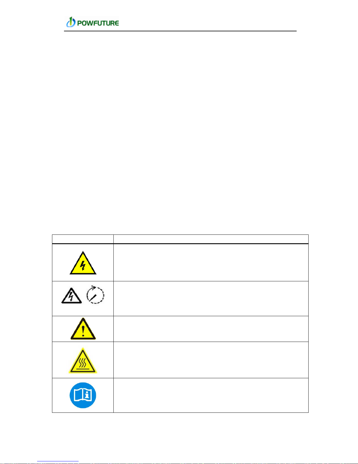
2.8 Explanations of Symbols on Inverter
Symbols, replace words on the equipment, on a display, or in manuals.
Symbol
Description
Dangerous electrical voltage
This device is directl y connected to public grid, thus all work to the
inverter shall only be carried out by qualified personnel.
30 minutes
DANGER to life due to high electrical voltage!
There might be residual currents in inverter because of large
capacitors. Wait 30 MINUTES before you remove the front lid.
NOTICE, danger!
This device directly connected with electricity generators and
public grid.
Danger of hot surface
The components inside the inverter will release a log of heat
during operation, DO NOT touch aluminum housing during
operating.
An error has occurred
Please go to Chapter 9 “Trouble Shooting” to remedy th e error.

Powfuture Science &Technology Co., Ltd
User Manual V2.0 14
This device SHALL NOT be disposed of in residential
waste
Please go to Chapter 8 “Recycling and Disposal” for proper
treatments.
Without Transformer
This inverter does not use transformer for the isolation function.
CE Mark
CE mark is attached to the solar inverter to verify that the unit
follows the provisions of the European Low Voltage and EMC
Directives Equipment with the CE mark fulfils the basic
requirements of the Guideline Governing Low Voltage and
Electro-magnetic Compatibility.
No unauthorized perforations or modifications
Any unauthorized perforations or modifications are strictly
forbidden, if any defect or damage (device/person) is occurred,
POWFUTURE shall not take any responsibility for it.
Trademark
No access for unauthorized personal
Symbol for the marking of electrical and electronics devices
according to Directive 2002/96/EC. Indicates that the device,
accessories and the pa cka gi n g mus t no t be di sposed as unsorted
municipal waste and must be collected separately at the end of
the usage Please follow Local Ordinances or Regulations for
disposal or contact an authorized representative of the
manufacturer fo r information concerning the de co mmi ssioning of
equipment.
Direct current
Alternating current
Protective conductor

Powfuture Science &Technology Co., Ltd
User Manual V2.0 15
Earth (ground) TERMINAL
PROTECTIVE CONDUCTOR TERMINAL
Isc PV
Absolute maxim um to t al PV ar ray s hor t cir c uit cu r ren t (d. c. ) t h a t
the inverter is rated to have connected to its PV input, under
worst-case conditions of ambient temperature, irradiance,etc.
This rating o f the PCE re fers to the a bsolute max imum curre nt the
PV input to the solar inverter is designed for under conditions of
expected use. Thi s diff ers f ro m the si mple s um o f the marke d Isc
ratings of the conn ected PV modules, since thos
e markings are
based on shortcircuit conditions under standard test conditions,
and may be exceeded in cold temperatures or with irradiance
above the standard level.
OVC
overvoltage category (OVC), numeral designation defining a
classification of transient overvoltage conditions
Vmax PV
maximum rated d.c. input voltage the PCE is designed to
withstand from the PV array (i.e. maximum opencircuit voltage)
under worst case conditions of ambient temperature, irradiance,
etc.
PV
Photovoltaic
+
DC terminal, indicating the polarity of the connections, positive,
all positive connections shall be made with Red
Insulated wire .
-
DC terminal, indicating the polarity of the connections, negative,
all negative connections with Black insulated wires.
PCS
Power conversion equ ipment, hereby is our DC/AC inverter.
service
personnel
a person having appropriate technical training and experience
necessary to be aware of hazards to which that person may be
exposed in performing a task and of measures to minimize the
risks to that person or other persons.

Powfuture Science &Technology Co., Ltd
User Manual V2.0 16
3. PRODUCT INFORMATION
3.1 Overview
Industrial Layout Reduced Heat Sink
3.2 Major Characteristics
Powfuture Grid-Connected solar inverter has following characteristics
which make POWFUTURE inverter “High Efficiency, High Reliability,
High price-to–performance ratio”.
Higher DC input voltage, can be connected with more PV panels.
Wider MPPT voltage range can fit in differ ent locations or various
weather conditions.
Qualified
personnel
Person adequately advise d or supe rvised by an elect rically ski lled
person to enable him o r her to perceive risks and to avoid hazards
which electricity can create. For the purpose of the safety
informat
ion of this ma nual, a "qualifie d person" is some one who is
familiar with requirements for safety, refrigeration system and
EMC and is authorized to energize, ground, and tag equipment,
systems, and circuits in accordance with established safety
procedures.
The inverter and e n d u se sys te m may only be commissioned a n d
operated by qualified personnel.

Powfuture Science &Technology Co., Ltd
User Manual V2.0 17
Higher MPP tracking accuracy, catch most of electricity from panels
and reduces your Payback Period.
Complete protection integrated within the inverter.
Also, following protection methods are integrated in inverter:
Internal over voltage
DC insulation monitoring
Ground fault protection
Grid monitoring
Ground fault current monitoring
DC current Injection monitoring
3.3 Product Identification
You can identify the inverte r by the sid e type label. Info rmation s uc h
as serial number (SN.), type of the inverter, as well as inverter
specifications are specified on the side type label. The type label is on
the middle part of the right side of the inverter housing.
(Side type label example as on Venus 5000TL)

Powfuture Science &Technology Co., Ltd
User Manual V2.0 18
3.4 Quality Certificate Card
When the single product passe d a series of automation per formance
and safety tests, a quality certificate card, which represents the
outcome of internal inspection, will be issued by POWFUTURE’s quality
assurance department rather than by the third party (authoritative
laboratory or testing institute). With this card we want to convince our
clients that POWFUTURE puts a new premium on the quality of
products.
3.5 Further Information
If you have any further questions concerning the type of accessories or
installation, please check our website www.Power-future.com or contact
our service hotline (+86)-27-86635836.
WARNINGS: In case of installation in PV system, startup of the unit
(i.e. start of desi gnate d ope ratio n) is pr ohibite d unt il it i s d ete rmine d
that the full system meets the requirements stipulated in the EC
Directive (2006/95/EC, 2004/108/EC etc.).
The grid-Connected Inverter leaves the factory completely connecting
device and ready for connection to the mains and PV supply. The unit
shall be installed in accordance with national wiring regulations.
Compliance with safety regulations depends upon installing and
configuring system correctly, including using the specified wirings. The
system must be installed only by professional assemblers who are
familiar with requirements for safety and EMC. The assembler is

Powfuture Science &Technology Co., Ltd
User Manual V2.0 19
responsible for ensuring that the end system complies with all the
relevant laws in the country where it is to be used.
The individual subass embly of the sy stem shall be inter connected by
means of the wiring methods outlined in national/international
regulations such a s the Natio na l Ele ctric Co de (NFPA) No. 70 . or VDE
regulation 0107.
To ensure the safe op eration of the dev ices, they may b e installed and
commissioned only by qualified pe rsonnel in ful l compliance with the
warnings referred to in this manual.
Open the package and pick the product, check that if there is any
distortion or impaired during transpo r tatio n, m e anw h ile , check that if
all the relating accessories and materials ar e here, you can see the
accessories list in the “Appendix”.
The instruction manual is an integral part of the unit and should
therefore be read and kept carefully.
It is recommended that the packa g in g sho uld no t be re mo ve d unti l
the unit is located in the installation site.
Do not dispose of packaging materials in the environment or leave
them within reach of children as they may represent a hazard.
Check that there are no signs of damage. Before attempting
installation and operation, check the information on the type
designation label of the unit to verify that the unit is of the correct type.
The label includes a n IEC ratin g and CE markings , a type code and a
serial number, which allow individual recognition of each unit.
Check the mechanical and electrical installation of the unit before
startup. Go through the checklist below together with another person.
Read the sections “Safety instruction and EC Directives” and “Interface
protection and Inverter setpoints’ on the previous pages of this manual
before you work on the unit.
During lifting procedures ensure the unit is firmly secured to avoid the
risk of accidental tipping or dropping.
Use a solid hard wall or metal structure.
Before installing the unit, agree with the customer the site.
Do not allow foreign object into the unit.
Not intended for multiple installation.
The rating plate and warning marking must be readable after
installation.

Powfuture Science &Technology Co., Ltd
User Manual V2.0 20
DANGER to life due to potential fire or electric shock.
With the inverter powered, comply with all prevailing
national regulations on accidents prevention.
This inverter will be directly connected with HIGH
VOLTAGE power generation device, the installation
must be performed by qualified personnel only in
compliance with national and local standards and
regulations.
Installed to be clear of obstruction. The enclosure must never be
covered.
The equipment is classed as one not accessible to the general public.
A suitable guarding which is keep min. 1.5mm distance around the
perimeter of the device is mandatory to prevent against access to
general public, especially for children or infirm persons when the
device is located in an unprotected area.
Make sure that dust from drilling does not enter the unit when
installing.
Do not place flammable materials near the unit. Failure to observe this
warning may result in a fire.
3.6 Mounting Sequence
1. Read the manual, pay special attention to the section on safety.
2. Install the inverter according to 《Installation Guide》.
3. Turn on PV by turning the DC switch on.
4. The inverter is now ready for operation.
4. ELECTRICAL CONNECTION
4.1 Safety
DANGER

Powfuture Science &Technology Co., Ltd
User Manual V2.0 21
The unit shall be installed in accordance with national wiring
regulations. Compliance with safety regulations depends upon
installing and configuring system correctly, including using the
specified wirings . The system must be ins talled only by pro fessional
assemblers who are familiar with requirements for safety and EMC.
The assembler is responsible for ensuring that the end system
complies with all the relevant laws in the country where it is to be used.
The individual sub-assembly of the system shall be interconnected by
means of the wiring methods outlined in national/international
regulations such a s the Natio na l Ele ctric Co de (NFPA ) No . 7 0. o r VDE
regulation 0107.
Power to the unit must be turned on only after installat ion work has
been completed. All electrical connections must be carried out by
qualified personnel in accordance with legislation in force in the
country concerned.
Before connecting, disconnect the connection between solar
generator and inverter and locked it to the open position during
installation. Place a warning sign “do not turn on – maintenance
in progress” on the external disconnecting switch when it is
shut down, and make sure that on-off remote controls are
inhibited. Refer to this manual, section 3.Safety instruction and
EC Directives – isolation device.
The open-circuit voltage of PV generator under worst case
conditions of ambient temperature, irradiance, etc. shall never
not exceed 500V, failure to observe this, it may cause elctric
shock hazards or completely damage of the inverter.
WARNING: HIGH LEAKAGE CURRENT, EARTH CONNECTION
ESSENTIAL BEFORE CONNECTING SUPPLY.
For the cables connected to PV inverter and Grid, choose the
appropriate wires according to the capacity of the inverter and PV
components.Calculate the max. input current and max. output current
of The inverter according to the actually system , inverter rating Label
NOTICE
Electrical connections shall be carried out in
accordance with the applicable regulations, such as
conductors, fuses, PE connection.

Powfuture Science &Technology Co., Ltd
User Manual V2.0 22
and Te chnical paramete r. For details, r efer to this manu al, Scetion 3
Safety instruction and EC Directives.
4.2 Selection of fuse and cables.
The cables we recommend are as follow.
Model
AC cable
(Cu) mm2
DC cable
AC Circuit breaker
A V IZ
Venus-3000TL 2x4,0+4,0 See below 25 250 1,45 x Iz
Venus-3600TL 2x4,0+4,0 See below 30 250 1,45 x Iz
Venus-4000TL 2x4,0+4,0 See below 30 250 1,45 x Iz
Venus-5000TL 2x4,0+4,0 See below 32 250 1,45 x Iz
Check that the operating time of the circuit breaker and fuse is
below 5 seconds.
To select power supply cables as specified in the above table (for
details, the cable manufacturer should be consulted.)
Dimension the mains (input power) and DC input cables according
to local regulations.
Double insulated shielded symmetrical copper cable with a max.
length of 5m is required for power circuit.
AC cable: Rated voltage of the cable amount to at least Uo/U=
300V/500V (in accordance with DIN VDE 0298), VDE or equivalent
approved cord, see section [Selection of fuse and cables].
DC cable: Code designation: PV1F; min.2, 5²mm, but not less than
nominal cross-sectional area of mains cable as specified as above.
Rated voltage AC U0/U 0, 6/1 kV; ambient temperature:–40 °C to
+90 °C; Max. Conductor temperature: 120 °C; TUV or equivalent
approved recommended.
All positive connections shall be made with Red insulated wire, and
all negative connections with Black insulated wires.
To guarantee the deg ree of protection IP54, the RS 485 plugs, cable
gland and cables must be matched to each other and all unused
connections must be provided with blanking plugs.

Powfuture Science &Technology Co., Ltd
User Manual V2.0 23
4.3 Overview of Connection Area
Recommended fuse rated current value
Object Description
A
DC fuse, outside the scope of our supply
B
Photovoltaic arrays
C
Logger, outside the scope of our supply
. User can order it
from POWFUTURE.
D
Remote PC, outside the scope of our supply. User can order it
from POWFUTURE.
E
AC fuse, outside the scope of our supply
F
Power grid
Model
DC fuse
( recommended)
AC fuse
( recommended)
Venus-3000TL
26A
26A
Venus-3600TL
30A
30A
Venus-4000TL
30A
30A
Venus-5000TL
32A
32A

Powfuture Science &Technology Co., Ltd
User Manual V2.0 24
5. DISPLAY
5.1 LCD Display
After the inverte r is started, system will be ini tia lize d and d ispla y the
connection screen showing as follows;
HostStatus:Waiting
2012-08-10 12:00:00
Safty Type:VDE0126
Connecting 60s ......
After the connect ion delay, if there are no faults found, system w ill
work normally, and if there is no button pressed, the system will
display the system current information, PV, AC and every day energy
record in turn;
DC AC
HostStatus:Normal
2012-08-10 12:00:00
400.6V
6.30A
229.2V
16.45A
HostStatus:Normal
2012-08-10 12:00:00
Fgrid 50.01 Hz
Igrid 16.45 A
Pac 3768 W
Vgrid 229.2 V
MaxP 3935 W
HostStatus:Normal
2012-08-10 12:00:00
Ipv1 6.30 A
Vpv1 400.6 V
Vpv2 400.6 V
Ipv2 3.21 A
TempR 37 C
TempA 34 C
HostStatus:Normal
2012-08-10 12:00:00
80
60
40
20
10
9
8
7
6
kWh
0
By pressing the “UP”, “DOWN”, “OK” and “ESC” button on display panel
you can also review all informat ion relevant to the system, suc h as
yield power, fault info, etc.

Powfuture Science &Technology Co., Ltd
User Manual V2.0 25
Main menu
HostStatus:Normal
2012-08-10 12:00:00
Current Value
Fault Information
History Data
Configuration
Device Information
Yield Power
Yield Power
Select “Yield Power ” optio n to ente r the sub menu and the c umulated
power generation by Day will be presented on the screen;
Yield power
HostStatus:Normal
2012-08-10 12:00:00
Today 13.60 kWh
Total 198.20 kWh
Current Value
Press “ESC” button to exit from the submenu and back to main menu.
Press the “down” button to select the “Current Value” option with “OK”
for confirmation. Subsequently, you have the free choice to check the
current value from the corresponding objects PV string1 or AC through
operation of “up” and “down” button.
PV String1
HostStatus:Normal
2012-08-10 12:00:00
AC
PV String2
PV String1 Power
HostStatus:Normal
2012-08-10 12:00:00
2523 W
PV String1 Voltage
400.6 V
PV String1 Current
6.30 A
PV String2 Power
HostStatus:Normal
2012-08-10 12:00:00
1285 W
PV String2 Voltage
400.6 V
PV String2 Current
3.21 A

Powfuture Science &Technology Co., Ltd
User Manual V2.0 26
AC Power
HostStatus:Normal
2012-08-10 12:00:00
3768 W
AC Voltage
229.2 V
AC Frequency
50.01 Hz
Fault Information.
Press “ESC” button to exit from the submenu and back to main menu.
Press the “down” button to select the “Fault Information.” option with
“OK” for confirmation. You are able to check all fault information
generated at different mome nts during the running of inverter or to
delete all the fault records.
Latest Fault
HostStatus:Normal
2012-08-10 12:00:00
Fault List
Delete Record
Error No: 2
HostStatus:Normal
2012-08-10 12:00:00
2012-06-08 09:41:50
Grid Volt Fault
Grid Freq Fault
Utility Loss
History Information
Press “ESC” button to exit from the submenu and back to main menu.
Pressing the “down” key to select the “History Information” option with
“OK” for confirmation you can check the power generation by figure or
list within 30 days.
Figure
HostStatus:Normal
2012-08-10 12:00:00
List
HostStatus:Normal
2012-08-10 12:00:00
80
60
40
20
10
9
8
7
6
kWh
0

Powfuture Science &Technology Co., Ltd
User Manual V2.0 27
Date Energy
HostStatus:Normal
2012-08-10 12:00:00
2012-08-10 13kWh
2012-08-09 32kWh
2012-08-08 46kWh
2012-08-07 39kWh
2012-08-06 49kWh
Configuration
Press “ESC” button to exit from the submenu and back to main menu.
Press the “down” button to select the “Configuration” option with “OK”
for confirmation. Subsequently, you are able to set up the “Language”,
“Date/Time”, “Address”, “Protection Set” and able to test the
overvoltage/undervoltage and overfrequency/underfrequency by
pressing the “Self Test” button.
HostStatus:Normal
2012-08-10 12:00:00
Date/time
Address
Language
Protection Set
Self Test
Language Set:
HostStatus:Normal
2012-08-10 12:00:00
Deutsch
Italiano
English
Españo
Dansk
Français
Date/Time Set:
2012-08-10 12:00:00
HostStatus:Normal
2012-08-10 12:00:00
Address Set:
HostStatus:Normal
2012-08-10 12:00:00
001
Protection Set:
Users need input password for protection setting, the interface is
showed as following

Powfuture Science &Technology Co., Ltd
User Manual V2.0 28
HostStatus:Normal
2012-08-10 12:00:00
PassWord:
0000
PassWord Set
The default password is 3816.You also can change the password by
selection the “Password Set” menu. Please remember the password
setting by yourself.
When Input the correct password, system protection parameters can
be set showing as follows.
HostStatus:Normal
2012-08-10 12:00:00
Parameter Set
Maxpower Set
Safety Type
Press “UP” or “DOWN” button to select safety type, parameter set or
maximum power set.
Safety Type
Safety Type
HostStatus:Normal
2012-08-10 12:00:00
VDE0126
Countdown Thr:
060S
Parameter Set
HostStatus:Normal
2012-08-10 12:00:00
Upper Volt:280.0V
Lower Volt:180.0V
Upper Freq:54.99Hz
Lower Freq:45.00Hz
DCI Set: 0.999A
These five parameters is set bit by bit , every bit is set by press ing the
“UP” or “DOWN” button. When setting is ok, please press the “OK”
button to set next bit, until the last bit of DCI Set to finish parameters
set.
MaxPower Set

Powfuture Science &Technology Co., Ltd
User Manual V2.0 29
MaxPower means the maximum power that system can output.
HostStatus:Normal
2012-08-010 12:00:00
5200 W
Password setting interface is showed as follows
HostStatus:Normal
2012-08-10 12:00:00
0000
New PassWord:
Original PassWord
Confirm PassWord:
0000
0000
First you shall input the current password correctly, and then press
“OK” button to set the new password, next input the new password
again to confirm the new password.
Self Test (Optional except Italy necessary)
Press the “down” button to select the “ S e lf T e s t” o ptio n w i th “OK” for
confirmation. Then machine will enlighten you as following.
HostStatus:Normal
2012-08-06 09:14:29
Self Test
OK CANCEL
Result of Test
If the “OK” button is pr essed, the machine w ill enter into “Self T est”
mode. The following is an example of self test. Every time the machine
will save the result of test automatically and cover the older test
record.
The first is the minimum frequency limi tatio n te st
FW Version:Msv200
HostStatus:Normal
2012-08-06 09:37:36
Min Freq CHECK
Threshold Reading
49.75Hz Waiting
100 mS Waiting
Waiting
While test is finished, system will show the results of test.

Powfuture Science &Technology Co., Ltd
User Manual V2.0 30
FW Version:Msv200
HostStatus:Normal
2012-08-06 09:37:58
Min Freq CHECK
Threshold Reading
49.75Hz 49.80Hz
100 mS 87mS
PASS
Then the maximum frequency limitation test is started.
FW Version:Msv200
HostStatus:Normal
2012-08-06 09:38:34
Max Freq CHECK
Threshold Reading
50.25Hz Waiting
100 mS Waiting
Waiting
While test is finished, system will show the results of test.
FW Version:Msv200
HostStatus:Normal
2012-08-06 09:38:59
Max Freq CHECK
Threshold Reading
50.25Hz 50.15Hz
100 mS 72 mS
PASS
Next is the minimum voltage limitation test
FW Version:Msv200
HostStatus:Normal
2012-08-06 09:39:36
Min Vol CHECK
Threshold Reading
190 V Waiting
200 mS Waiting
Waiting
While test is finished, system will show the results of test.
FW Version:Msv200
HostStatus:Normal
2012-08-06 09:40:24
Min Vol CHECK
Threshold Reading
190 V 198.5 V
200 mS 096 mS
PASS
The Last is the maximum voltage limitation test
FW Version:Msv200
HostStatus:Normal
2012-08-06 09:41:04
Max Vol CHECK
Threshold Reading
265 V Waiting
100 mS Waiting
Waiting
While test is finished, system will show the results of test.

Powfuture Science &Technology Co., Ltd
User Manual V2.0 31
FW Version:Msv200
HostStatus:Normal
2012-08-06 09:41:51
Max Freq CHECK
Threshold Reading
265 V 262 V
100 mS 083 mS
PASS
After complete the all test, you can view the final re sults b y se le ctio n
the “Result of Test” menu.
Press “UP” or “DOWN” button to view the result of minimum/maximum
frequency test and minimum/maximum voltage test result.
FW Version:Msv200
HostStatus:Normal
2012-08-10 12:00:00
Min Freq CHECK
Threshold Reading
49.75Hz 49.80Hz
100 mS 87mS
2012-08-06 09:41:56
FW Version:Msv200
HostStatus:Normal
2012-08-10 12:00:00
Max Freq CHECK
Threshold Reading
50.25Hz 50.15Hz
100 mS 72 mS
2012-08-06 09:41:56
FW Version:Msv200
HostStatus:Normal
2012-08-10 12:00:00
Min Vol CHECK
Threshold Reading
190 V 198.5 V
200 mS 096 mS
2012-08-06 09:41:56
FW Version:Msv200
HostStatus:Normal
2012-08-10 12:00:00
Max Freq CHECK
Threshold Reading
265 V 262 V
100 mS 083 mS
2012-08-06 09:41:56
Device Information
Press “ESC” button to exit from the submenu and back to main menu.
Press the “DOWN” button to select the “Device Information” option
with “OK” for confirmation. Then you can get access to system
information involving company information and ARM software version

Powfuture Science &Technology Co., Ltd
User Manual V2.0 32
HostStatus:Normal
2012-08-10 12:00:00
Product SN:
Machine Type:
01111AAX28B4U4X3
Venus5000
Safety Type:
VDE0126
HostStatus:Normal
2012-08-10 12:00:00
Monitor FW Version:
Msv200-20120730
Master FW Version:
Vdv200-00000000
Slave FW Version:
Vdv200-00000000
5.2 Error Message
If any of the following messages occurs in LCD Screen, or the status of
“Fault” LED is on, there is one or m ore error that has b een detected by
POWFUTURE Inverter.
Error No. Information
0 Grid Volt. Fault
1 Grid Volt .10min Fault
2 Grid Freq. Fault
3 Utility Loss
4 AC-Over current
5 DC Bus-Over voltage
6 PV-Over voltage
7 Device Fault
8 Cur. Sensor Fault
9 Comm. disturbed
10 Consistence Fault
11 GFCI Fault
12 GFCI Device Fault
13 DC INJ Fault
14 DC INJ Device Fault
15 Isolation Fault
16 Varistor Fa ult

Powfuture Science &Technology Co., Ltd
User Manual V2.0 33
17 CPU Ref 2.5V Fault
18 EEPROM R/W Fail
19 Relay Fault
20 Over-temperature
5.3 Troubleshooting
Error No. Message Corresponding Action
0
“Grid volt. Fault”
The gird voltage has exceeded the
permitted range according to local
gird regulations.
• Check the grid voltage.
• Check the grid connection
of the inverter.
If the grid voltage exceeds the
permitted range because of
local grid conditions, pl ease ask
the utility operator if the
voltage can be adjusted at the
feed-in point or if changes in
the values of the monitored
operational limits are possible.
If the grid vol tage tha t checke d
is within the permitted range,
yet this error is still showing in
the LCD screen, please contact
Powfuture Service Line.
1
“Grid volt. 10min Fault”
The average gird voltage over 10
minutes has been outside the
permitted range according to local
gird regulations.
Following causes might lead to
error 0 or error 1:
• Grid volt
age is too high at the
point of common coupling to the
inverter.
• Grid impedance a t t he ter mi nal
of the inverter is too high.
For safety consideration, the
inverter will disconnect itself from
the grid for a short period of time,
and it will reconnect to th
e grid
automatically af ter a short perio d of
time if the grid voltage is back to
the permitte d r a nge.
2
“Grid Frequency Fault”
The grid frequency has left the
permitted range.
For safety consideration, the
inverter will disconnect itself from
the grid f or a short period of time,
and it will reconnect to the grid
automatically af ter a short perio d of
time if the grid fre quency is back to
the permitte d r a nge.
• Within safety scope, check
the grid frequency and obse rve
how often major deviations
occur.
If there are repeated frequency
turbulences which lead to this
error, ple ase co n ta ct Powfuture
Service Line.

Powfuture Science &Technology Co., Ltd
User Manual V2.0 34
Error No. Message Corresponding Action
3
“Utility Loss”
The inverter has detected an error
in the cabling and cannot connect
to the grid.Following causes might
lead to this error:
•
Grid connection installation
failure.
• Cabling failure.
• Incorrect country set ti ng.
• Check AC installation.
• Check grid connectio n.
• Check if the co untry setti ng
is correct:
− Via LCD screen
If this error is not solvable,
please cont
act Powfuture
Service Line.
4
“AC-Over current”
The detected AC current has
exceeded the pre-
set Max. AC
Current.
Following causes might lead to this
error:
•
Short circuit happens in the
output circuit.
If this event occurs often:
•
Please contact Powfuture
Service line.
5
“DC Bus-Overvoltage”
The voltage of the Bus which
paralleling connected with the
string is too high.
Following causes might lead to this
error:
• The DC input vo ltage connecte d
to the inverter is too high.
• Sudden DC surge.
For safety conside
ration, the
inverter will shutdown itself.
•
Please immediately
disconnect the inverter from
the PV strings (se e ch a p te r 6 .5
“DC side Disconnection”) or
else the inverter might be
damaged.
•
Check the DC voltage of
the strings fo r adherence to the
maximum inpu
t voltage of the
inverter, before you reconnect
the inverte r to the PV st rings.
6
“PV-Overvoltage”
The DC input voltage which
connects to t he inve rter is too high.
Following causes might lead to this
error:
• The open-
circuit voltage of the
PV generator is
higher than the
maximum DC input voltage of the
inverter.
• Sudden DC surge.
•
Junction temperature of solar
panel too low.
•
Please immediately
disconnect the inverter from
the PV strings (se e ch a p te r 6 .5
“DC side Disconnection”) or
else the inverter might be
damaged.
•
Check the DC voltage of
the strings fo r adherence to the
maximum input voltage of the
inverter, before you reconnect
the inverte r to the PV st rings.

Powfuture Science &Technology Co., Ltd
User Manual V2.0 35
Error No. Message Corresponding Action
7
“Device Fault”
A fault ha s o ccur red i n o ne o r more
major components of the inverter.
For safety consideration, the
inverter will shutdown itself.
If this event occurs:
−
Please contact
Powfuture Service line.
8
“Current Sens o r Fault”
A fault ha s o ccur red i n o ne o r more
current sensor of the inverter.
For safety
consideration, the
inverter will shutdown itself.
If this event occurs:
−
Please contact
Powfuture Service line.
9
“Comm. Disturbed”
A fault has occurred in the internal
communication of the inverter.
However, the inverter continues
feeding into the grid.
If this event occurs often:
−
Please contact
Powfuture Service Line.
10
“Consistence Fault”
Following causes might lead to this
error:
• Interference device
If this event occurs often:
−
Please contact
Powfuture Service Line.
11
“GFCI Fault”
The inverter has detected a ground
fault in the PV generator.
•
The installer of the PV
generator must solve the
ground faults before you
re-connect t he s tri ng s .
• If this error is not solvable,
please contact Powfuture
Service Line.
12
“GFCI Device Fault”
The internal sensor h
as detected
that the GFCI Device is out of
function.
For safety consideration, the
inverter will shutdown itself.
If this event occurs:
−
Please contact
Powfuture Service Line.
13
“DC INJ Fa ult”
The direct component of the AC
current is out of the permitted
range.
If this event occurs often:
−
Please contact
Powfuture Service Line.
14
“DC INJ Device Fault”
A fault has occurred in the sensor
which detect s the direct com ponent
of the AC current.
For safety consideration, the
inverter will shutdown itself.
If this event occurs:
−
Please contact
Powfuture Service Line.

Powfuture Science &Technology Co., Ltd
User Manual V2.0 36
Error No. Message Corresponding Action
15
“Isolation Fault”
There is a sudden isolation fault
which is detected by the inverter.
Normally this fault will only exist for
a very short period of time and shall
not have any bad influence to the
inverter.
If this event occurs often:
−
Please contact
Powfuture Service Line.
16
“Vari sto r Fault”
At least one of the varistors from
the DC or AC side is defected.
Following causes might lead to this
error:
• Varis
tor is bust due to
over-voltage protection.
If this event occurs:
−
Please check the
varistors as chapter 5.6
“Check Varistors”.
If this error is not solvable,
please contact Powfuture
Service Line.
17
“CPU Ref 2.5V Fault”
The CPU voltage that detected by
i
nternal sensor is deviating the
pre-set 2.5V reference line.
If this event occurs:
−
Please contact
Powfuture Service Line.
18
“EEPROM R/W Fail”
Internal devic e f a ul t.
For safety consideration, the
inverter will shutdown itself.
If this event occurs:
− Please contact
Powfuture Service Line.
19
“Relay Fault”
A fault has occurred in the relay
which will automatically disconnect
the inverter from the grid.
For safety consideration, the
inverter will shutdown itself.
If this event occurs:
−
Please contact
Powfuture Service Line.
20
“Over-temperature”
The delivered power of the inverter
was reduced below rated power
because of abnormal temperature
within 0.5s.
Following causes might lead to this
error:
•
At least one or more of the
thermally monitored varistors are
defective.
• Overheating inside.
• Not sufficient v entilation.
If this event occurs of t en:
•
Please ensure sufficient
ventilation.
• Check the varis to r s.
• If this error is not solvable,
please contact Powfuture
Service Line.

Powfuture Science &Technology Co., Ltd
User Manual V2.0 37
6. RECYCLING AND DISPOSAL
To comply with European Directive 2002/96/EC on waste Electrical and
Electronic Equipment and its implementation as national law, electrical
equipment that has reached the end of its life must be collected
separately and retur ned to a n approve d recyc ling fa cility. Any device
that you no longer require d must be returned to your dealer or you
must fine an approved collection and recycling facility in your area.
Ignoring this EU Directive may have severe affects on the environment
and your health.
7. MAINTENANCE
Normally, the inver te r needs no maintenance o r calib ra tio n . It s ho uld
be ensured, however , that the cool ing is not o bstructed an d that the
inverter is kept dry.
To ensure the functiona lity of the DC switch, all switches should be
switched on and off (by t urnin g the sw i t c h to o n and o ff po sitio ns te n
times)once a year.
7.1 Cleaning the Cabinet
Clean inverter with a soft cloth. Do not use aggressive chemicals,
cleaning solvents or strong detergents to clean the inverter.
7.2 Cleaning the Heat Sink
In order to secure proper function and long inverter life, it is essential
that the free air circulation around the heat sink is not obstructed.
WARNIN
This device SHALL NOT be disposed
of in residential waste.

Powfuture Science &Technology Co., Ltd
User Manual V2.0 38
No use-serviceable parts inside, before servicing and in the
event of internal malfunction the unit, send the inverter to
authorized representative or manufacturer!
Never operate this product and change any part of inverter yourself.
Only trained and authorized professional personnel WHO ARE
FAMTLIAR WITH THE REQUIREMENTS OF SAFETY was allowed to
perform servicing and maintenance work.
Wear gloves and safety glasses.
Turn off the device with the button on the front panel.
Turn off the power fuses of the device feeder cable.
Turn off DC isolating switc h in t he PV generat or and inverter.
Disconnect AC
Connection an d protec t aga inst be ing s witche d on aga in a ccide nta lly,
refer to this manual, sect ion “Safety instruction a nd EC Directives –
Isolating device”.
Waiting for 45 minutes since the internal capacitors require this long to
discharge sufficiently, the n loosen cable glands, disconne ct covering
plate from the connection area. Disconnect the power cables and
communication cables.
Unlock device by removing the holding screws in back under the
bottom cover, li ft the device from the wall and send it to a uthorized
representative or manufacturer.
You may also call authorized representative or manufacturer to
remove the invert er.
Safety checks
Safety checks should be performed at least every 12 months by
manufacturer’s qualified person who has adequate training,
knowledge, and practical experience to perform these tests. The data
should be recorded in an equipment log. If the device is not functioning
properly or fails any of tests, the device has to be repaired.
For safety check details, refer to this manual, section “Safety
instruction and EC Directives”.
Maintain periodically
Only qualified person may perform the following works.
During the process of using the inverter, the manage person shall
examine and maintain the machine regularly. The concrete operations
are as follow.
1、Check that if the inlet and outlet of the inverter are blocked, if the
fans work normally, the machine can be cleaned and abso rbed dust
when necessary. This work shall be check time to time.
2、Check that if the indicators of the inverter are in normal state, check
if the keys of inver t e r ar e in n or ma l state, check that if the dis p lay of
the inverter is normal. This check should be performed at least every 6
months.

Powfuture Science &Technology Co., Ltd
User Manual V2.0 39
3、Check if the input and output wires are damaged or aged. This check
should be performed at least every 6 months.
4、 You should get the inverter panels cleaned and their security
checked at least every 6 months.
Before cleaning the inverter:
Wear gloves and safety glasses.
Turn off the device with the button on the front panel.
Turn off the power fuses of the device feeder cable.
Turn off DC isolating switch in the PV generator and inverter.
Disconnect AC connection and protect against being switched on again
accidentally, refer to this manual, section 3 Safety instruction and EC
Directives – Isolating device.
Clean the inverter with wet cloth carefully.
8. GUARANTY SCOPE AND GUARANTY SERVICE
8.1 POWFUTURE Factory Guaranty Scope
This guaranty declaration is solely applied to the following
POWFUTURE Grid-Connected Solar Inverter:
Venus – 3000TL
Venus – 3600TL for G83
Venus – 4000TL
Venus – 5000TL
For the above named products, you will receive a POWFUTURE factory
warranty card whic h will valid for 5 years from the date of purchase.
The POWFUTURE factory warranty covers any costs which you incur for
repair or replacement parts during the agreed period beginning at the
date of purchase of the device, subject to the guaranty conditions
listed below. This is not associated with a durability warranty.
You have the possibility of purchasing an extension of this
POWFUTURE factory warranty within the 5 years term of the
POWFUTURE factory warranty. The prices are based on the respective
POWFUTURE price list valid a t the time the warranty ext ension was
signed.
8.2 Guaranty Conditions
This guaranty declaration is solely applied when any defect of
POWFUTURE inverter is detected.
If a device becomes defective during the POWFUTURE guaranty period,

Powfuture Science &Technology Co., Ltd
User Manual V2.0 40
and it is proved that further functional performance is impossible, the
device will be, as selected by POwfuture:
Repair the defect at the factory free o f cha rge w it hin t he g uar anty
period.
Exchange for a replacement device of equivalent value according to
model and age.
If it is the latter case, the remainder of the warranty entitlement will be
automatically transferred to the replacement device. In this case, you
will not receive a new certificate since your entitlement is already
documented at POWFUTURE if the rest warranty period is more than 1
year. If a replacement occurs when rest warranty period is less than 1
year, it will automatically extend the rest warranty period to exactly 1
year.
POWFUTURE will only perform guaranty service only if the user
provides a copy of invoice which was issued to the user by the dealer
and a completed warranty c ard. If any one of these two is missing,
POWFUTURE has the rights to deny the guaranty service or only
provide paid service.
8.3 Guaranty Exclusion
Guaranty declaration is excluded in the following cases:
Transport damage
Improper installation and installation that does not comply with
standards
Use of the devices in ways not intended
Improper operations without following the user manual
Operation of units with defective protective equipment which might
lead to damage
Unauthorized modifications to the units or repair attempts
NOTICE
If exchange for a replacement device of equivalent
value according to mode l and age is needed. The
defected unit must, where possible, be returned in
its original or equivalent packaging.

Powfuture Science &Technology Co., Ltd
User Manual V2.0 41
Influence of foreign objects and force majeure (lightning, grid over
voltage, severe weather, fire)
Insufficient ventilation of the unit
Failure to observe the relevant safety regulations
If the device becomes defective when in any of the above cases,
POWFUTURE will not perform guaranty service and the user shall take
whole responsibility for the defects.
9. ACCESSORIES
You will find the corresponding accessories and replacement parts for
you product in the following overview. If required, you can order these
from POWFUTURE.
Description Brief description
Powfutrue order
number
DC plug connector Field plug for condu ctor H4CF(M)C6DC
AC plug connector Field plug for conductor 96-031-4154-3

Powfuture Science &Technology Co., Ltd
User Manual V2.0 42
10. CONTACT
Wuhan Headquarter
Wuhan POWFUTURE Science and Technology Co.,Ltd.
Canglong Building
Changzui Optoelectronics Industrial Park
No. 18 Jiufeng Street, Jiangxia District,
Wuhan, 430074, Hubei, P.R.China
Tel: (+86)-27-86635836
Fax: (+86)-27-86635896
Email: info@ Power-future.com
www.Power-future.com
Service line
Tel: (+86)-27-86635836
Fax: (+86)-27-86635896
Email: service@Power-future.com
www.Power-future.com

Powfuture Science &Technology Co., Ltd
User Manual V2.0 43
11. ABBREVIATION
LCD
Liquid Crystal Di spl ay
LED
Light Emitting Diod e
MPPT
Maximum Power Po int Tr acki ng
PV Photovoltaic
GFCI Gro und Faul t Circ uit In ter rupter
Vdc Voltage at the DC s ide
Vac Voltage at the AC s ide
Vmpp
Voltage at the Max imum Powe r Poin t
Impp
Amperage at Maximum Power Point
Voc
Open Circuit Vo ltag e
Isc Short Circuit Current
AC Alternating Cur rent ( Form of e lectrici ty supp lied by
Utility Compan y )
DC Direct Curre nt ( Fo rm of electr icity genera ted by PV
modules )
VDE
0126-1-1
German standards for establishing suitability for Grid
Connection of the Inverter.
UL 1741
US standards for establishing suitability for Grid
Connection of the Inverter.

Powfuture Science &Technology Co., Ltd
User Manual V2.0 44

 Loading...