

Page 1
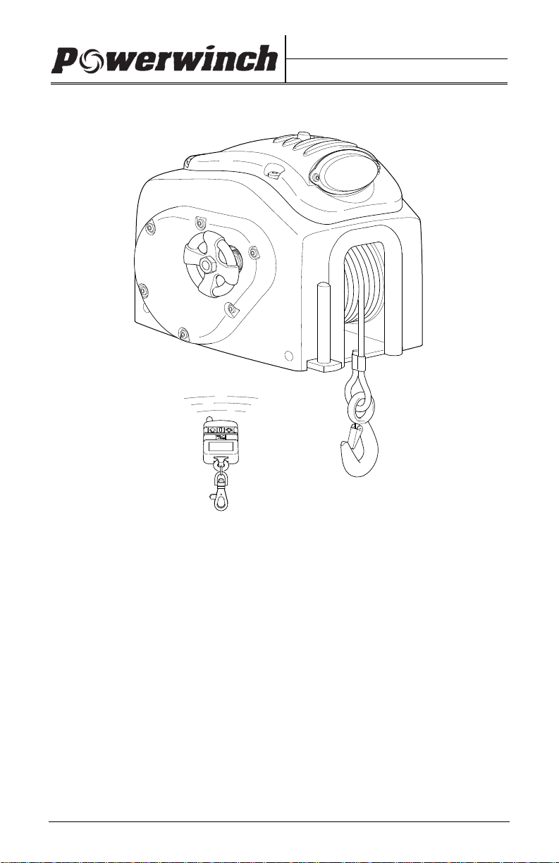
OWNER'S MANUAL
RC23 & RC30 Trailer Winches
pwRC003
12 Volt Powered Winch
Wireless Remote Operation
Remote Power-In / Freewheel-out operation
Spot Light Mounted in Housing
Refer to the Specifications Page for Load Capacity
These instructions apply to all models listed. Details and procedures unique to a
specific model are labeled appropriately.
P5593104AV Printed in USA September, 2008
Page 2

PROPRIETARY STATEMENT
The Powerwinch RC23 and RC30 Trailer Winches are products of Carefree of
Colorado, located in Broomfield, Colorado, USA. The information contained in or
disclosed in this document is considered proprietary to Carefree of Colorado. Every
effort has been made to ensure that the information presented in the document is
accurate and complete. However, Carefree of Colorado assumes no liability for errors
or for any damages that result from the use of this document.
The information contained in this manual pertains to the current configuration of the
models listed on the title page. Earlier model configurations may differ from the
information given. Carefree of Colorado reserves the right to cancel, change, alter or
add any parts and assemblies, described in this manual, without prior notice.
Carefree of Colorado agrees to allow the reproduction of this document for use with
Carefree of Colorado products only. Any other reproduction or translation of this
document in whole or part is strictly prohibited without prior written approval from
Carefree of Colorado.
TABLE OF CONTENTS
Safety Information ................................................................................... 1
General Safety Information ........................................................................... 1
Specifications .......................................................................................... 2
Installation ............................................................................................... 3
Mounting the Unit .......................................................................................... 3
Assembling the Pulley Block ......................................................................... 3
Wiring the Unit ............................................................................................... 4
The Remote Transmitter ............................................................................... 4
Testing the Remote ................................................................................ 4
Programming a Replacement Remote ................................................... 5
Remote Operational Notes ..................................................................... 5
Replacing the Remote Battery ............................................................... 5
Operating the Winch ............................................................................... 6
Unloading The Boat....................................................................................... 6
Loading the Boat ........................................................................................... 6
Manual Override Switch ................................................................................ 7
Emergency Hand Crank ................................................................................ 7
Operating the Light ........................................................................................ 8
Replacing the Light Bulb ........................................................................ 8
Maintenance ............................................................................................. 8
Lubrication ..................................................................................................... 8
Cable Replacement ....................................................................................... 9
Troubleshooting Guide ................................................................................ 10
Replacing the In-Line Fuse .................................................................. 11
Illustrated Parts List ..................................................................................... 12
Cover and Electronics .......................................................................... 12
Gear Assemblies .................................................................................. 14
Warranty ................................................................................................. 17
Powerwinch 2145 W. 6th Avenue Broomfield, CO 80020
by Carefree of Colorado 303-469-3324 ♦ www.powerwinch.com
Page 3

POWERWINCH RC 23 & RC30 TRAILER WINCHES
SAFETY INFORMATION
WARNING
A WARNING INDICATES A POTENTIALLY HAZARDOUS SITUATION WHICH, IF NOT AVOIDED,
COULD RESULT IN DEATH OR SERIOUS INJURY AND
/OR MAJOR PROPERTY DAMAGE.
CAUTION
A CAUTION INDICATES A POTENTIALLY HAZARDOUS SITUATION THAT MAY CAUSE MINOR
TO MODERATE PERSONAL INJURY AND
ALERT AGAINST UNSAFE P RACTIC ES
NOTE: A note indicates further information about a product, part, or step.
Tip: A tip provides helpful suggestions.
/OR PROPERTY DAMAGE. IT MAY ALSO BE USED TO
.
GENERAL SAFETY INFORMATION
The following Safety Precautions Must be Followed at ALL Times
Failure to follow the warnings and cautions in this manual could result in
serious injury and/or property damage.
Thoroughly read the manuals furnished with this product and be familiar with the
controls. Do not allow individuals to operate the winch without understanding the
safe operation and procedures for the equipment.
WARNINGS
ALWAYS unplug the wiring harness before attempting to install, relocate,
service or perform maintenance on the unit.
NEVER use the winch to lift or move people or animals.
NEVER use the winch for overhead lifting.
NEVER attempt to pull a load greater than the rated load of the winch.
NEVER use the winch to exclusively hold, support or permanently secure the
load. Use separate straps to support the load.
NEVER use the winch alone to secure the boat to the trailer during transit.
Use separate straps or equivalent to secure the boat to the trailer.
ALWAYS stand away from the winch during operation. ALWAYS stand clear of
the area behind and between the load or anchor point and the winch.
Serious injury could occur if the cable breaks.
ALWAYS keep hands clear of the cable spool (drum area).
ALWAYS wear leather gloves when handling the cable. Steel cable can
cause serious damage to hands.
NEVER wear loose fitting clothes, scarves, ties or jewelry when operating the
winch. Loose clothing can become caught in moving parts.
1
Page 4

RC 23 & RC30 TRAILER WINCHES POWERWINCH
SPECIFICATIONS
Light Switch
Override/Learn
Switch
Clutch Control
e
t
S
9”
R
e
e
l
s
e
a
Emergency
Crank Handle
Knob
12V Light
Power Socket
9 1/2”
11 1/2”
pwRC005
Various load conditions affect winch performance. The line pull required for a
specific application depends on the weight of the load, condition of the trailer
rollers, and the degree of the loading ramp incline. The chart below is based on
a single line pull and is provided as a guideline in calculating pulling capabilities.
WARNING
THE CABLE FASTENERS ON THIS OR ANY WINCH ARE NOT DESIGNED TO HOLD RATED
LOADS INDEPENDENTLY
Chart 1. Approximate Rolling Load Capacities (values are in po unds)
% Incline Level 5% 10% 20% 30% 50% 70% 100%
˚ Incline 0˚ 3˚ 6˚ 11˚ 17˚ 26˚ 35˚ 45˚
RC23
RC30
A 10% incline (6˚) is 1 foot rise in 10 feet.
To convert from pounds (lbs) to kilograms (kgs) divide by 2.2.
Capacity can be increased by using a pulley block.
24000 13340 10040 6800 5220 3720 3060 2580
40000 23345 17570 11900 9135 6510 5355 4515
Chart 2. Winch & Boat Capacities (values are in pounds)
Model
RC23
Vertical Lift
Capacity Double Line Pull
2,400 4300 7500 17-23 Feet
RC30
* Boat size and weight is approximate and varies depending on boat type.
When calculating boat weight, use the fully loaded weight that includes boat,
motor, fuel, water, gear etc.
Chart 3. Approximate Rolling Load Capacities (values are in po unds)
Model
RC23
Line Speed @
Cap a c i t y ( F P M ) Gear Ratio Voltage
14 225:1 12 vdc 60 amps 34 lbs
RC30
Noise Level during Operation: less than 98db (A).
2
. ALWAYS LEAVE A MINIMUM OF FIVE WRAPS OF CABLE ON THE
DRUM TO ACHIEVE THE RATED LOAD VALUES
Approximate
Boat Weight*
.
Approximate
Boat Size*
4000 7500 11500 23-30 Feet
Circuit
Breaker Unit Weight
8 450:1 12 vdc 60 amps 36 lbs
Page 5
POWERWINCH RC 23 & RC30 TRAILER WINCHES
INSTALLATION
MOUNTING THE UNIT
The following instructions are for standard mounting of the winch. A quick mount
kit is available (p/n P7700000AJ). If installing with the quick mount kit, follow the
directions with the kit. Steps 3, 4 and 6 apply when using the kit.
The winch can be mounted on the trailer in the same position and location as an
existing hand winch.
1. Remove the existing hand winch.
2. Position the unit on the trailer mount stand.
3. Confirm that the winch's cable hook and the bow eye on the boat are at the
same height when the boat is in the fully loaded position on the trailer.
If the bow eye is too high, extra pull is required of the winch and extra stress
is exerted on the boat's stern and bow eye.
If necessary to create equal height, raise or lower the winch stand. In most
cases, trailer manufacturers have adaptors available for use with a winch.
4. Confirm that there is a minimum of 12 inches clearance between the winch
and the bow eye when the boat is in the fully loaded position. If necessary,
extend the bow stop to obtain the clearance.
5. Bolt the unit using a minimum of two (2) 3/8" grade 5 machine bolts and lock
nuts. If the existing mounting holes do not line up with the winch, use the
bottom of the winch as a template and drill two (2) 7/16" holes in the
mounting surface of the trailer stand.
6. If using a double line pull (using a pulley block), install a 3/8" eyebolt on the
stand as close as possible to the base of the winch.
12” minimum
Level
Pulley Block
Eye Bolt
ASSEMBLING THE PULLEY BLOCK
1. Place the two screws through one of the teardrop plates
and hold in place.
2. Slide a bushing over each screw.
3. Slide the pulley wheel and hook over the bushings as
shown. The components fit loosely on the bushings.
4. Wrap the cable around the pulley.
5. Place the second tear drop plate over the screws and
secure using the washers and nuts provided.
Bow
Eye
pwRC006
pwRC014
3
Page 6
RC 23 & RC30 TRAILER WINCHES POWERWINCH
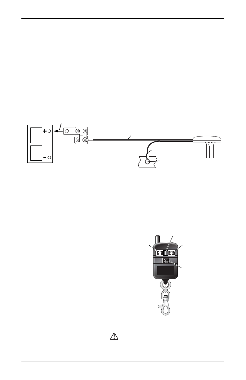
WIRING THE UNIT
The following instructions are for permanently wiring the winch. Two additional wiring
kits are available and sold separately: A universal bumper wiring kit (p/n P7702101AJ)
and a quick connect wiring harness (p/n P7866000AJ) for temporary connections. If
installing one of the kits, follow the directions with the kit.
1. Attach the circuit breaker to the battery's
POSITIVE (+) post or positive (+) terminal of
the starter solenoid.
2. Attach the ground wire (black) to the vehicle frame. Clean the metal frame with a
wire brush or equivalent then attach the ground lug using a 5/16" bolt and lock nut
(bolt and nut not furnished).
3. Route the wire under the vehicle and along the frame. Avoid sharp edges and
moving parts. Secure the wire to the frame approximately every 18" using nylon
ties or equivalent.
Connect To Positive (+)
Post of Vehicle Battery
12V Vehicle Battery
60 amp
Circuit Breaker
Red Wire
Secure Harness to Frame
Approximately Every 18”
Black Wire
Attach Ground
to Vehicle Frame
Power Plug
to Winch
pwRC007
NOTE: If the winch does not operate, follow the troubleshooting guide on page 10
and check the in-line fuse (page 11) before returning the winch.
THE REMOTE TRANSMITTER
The RC23 and RC30 winches are equipped with to operate with a RF (Radio
Frequency) transmitter and receiver. The transmitter and receiver are factory
programmed to communicate with each other.
Testing the Remote
1. Connect the 12V power cord to
the winch.
2. Press and hold the remote's
ON/OFF button for 3 seconds.
The blue LED will illuminate and
the winch light will flash.
3. Loosen the clutch knob (turn
counter clockwise) to prevent the
winch from pulling the cable in.
4. Press and hold the
button
Winch IN
Press to Pull
Cable In
Blue LED
On When Transmitting
Winch Light
Press
ON/OFF
ON/OFF
Press and Hold
for 3 Seconds to
Turn On Remote
and verify that the motor is
running. Release the button.
If the motor runs, the winch is
pwRC008
ready for use.
5. Tighten the clutch knob, the winch can now pull the boat onto the trailer.
CAUTION
WHEN NOT IN USE, PRESS THE ON/OFF BUTTON TO TURN OFF THE REMOTE. THIS WILL
PREVENT THE WINCH FROM ACCIDENTALLY OPERATING WHEN NOT IN USE
.
4
Page 7

POWERWINCH RC 23 & RC30 TRAILER WINCHES
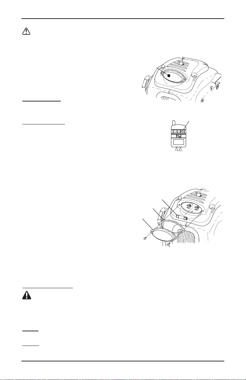
Programming a Replacement Remote
1. Connect the 12V power cord to the winch.
2. On the back of the winch, hold the learn switch in
Press to Learn
the up position until the winch light comes on (5-20
seconds).
Manual Override
3. Release learn switch.
4. While the winch light is on, push the arrow button on
pwRC009
the remote until the light on the winch flashes 1 time.
5. On the remote, hold the
ON/OFF button until the winch light flashes.
6. Test operation using the procedure given previously.
Remote Operational Notes
The transmitter (remote) is an electronic device and should be kept dry at all times.
The remote operates best within a 10'-15' range from the winch (receiver).
Maximum operating distance is 30'-40'. Actual distance may vary depending on
the environment the remote is used in.
For best operation, hold the remote level with or above the winch.
The transmitter and receiver have been tested and complies with the limits for a
Class B digital device pursuant to Part 15 of the FCC Rules.
This equipment generates, uses and can radiate radio frequency energy. There is
no guarantee that interference will not occur in any particular installation. This
interference may affect radio and television reception.
To prevent accidental operation of the winch and to preserve battery life, the
remote must be turned off after every use.
Replacing the Remote Battery
The remote uses a 12V size A23 battery. Batteries are available through your local
battery outlets. For best performance, the battery should be changed every 3 months
or twice during the boating season. Actual battery life is dependent on frequency of
use, environmental conditions and the condition of the remote.
1. Remove the small screw from the back of the remote.
2. Carefully separate the two halves of the remote.
NOTE: When removing the old battery, make note of the polarity of the
battery. When inserting the new battery, place the negative end
agains the coil spring terminal.
3. ;Remove the old battery and insert the new battery.
4. Reattach the covers and screw removed previously.
5
Page 8

RC 23 & RC30 TRAILER WINCHES POWERWINCH
OPERATING THE WINCH
WARNINGS
To avoid personal injury and property damage, clear the area around and
behind the boat of people, animals and obstructions before loading or
unloading the boat.
Never stand between or behind the load or anchor point and the winch.
Serious personal injury could occur if the cable breaks.
ALWAYS wear leather gloves when handling the cable. Steel cable can
cause serious damage to hands.
NEVER use the winch alone to secure the boat to the trailer during transit.
Use separate straps or equivalent to secure the boat to the trailer.
UNLOADING THE BOAT
1. In not previously done, attach the winch cable hook to the bow eye on the boat.
2. Connect the power to the winch. The power cord plug goes into the socket on the
right side of the winch.
3. Remove the tie down straps from the boat.
4. Slowly turn the clutch knob (counterclockwise) to release the winch brake.
5. Allow the boat to slide off the trailer. If necessary, the clutch knob can be
tightened to slow the speed of the boat.
6. When the boat is in the water, release the cable hook.
7. Tighten the clutch control knob clockwise until finger tight to set the brake.
8. While maintaining tension in the cable, press the
Roll the cable up completely. D
damage to the cable and winch components could occur.
9. Secure the cable hook to prevent any accidental injury or damage.
O NOT allow the cable to roll up loosely,
button on the remote.
LOADING THE BOAT
1. Connect the power to the winch. The power cord plug goes into the socket on the
right side of the winch.
2. Align the boat and trailer.
3. Loosen the clutch knob (turn counterclockwise) and free-wheel the cable to the
boat. Attach the hook to the eye on the bolt.
NOTE: If the winch cable is initially difficult to pull out, try engaging the
motor for a few seconds with the clutch fully released. This
should free the clutch allowing the cable to pull out.
4. Tighten the clutch control knob clockwise until finger tight to set the brake.
D
O NOT over tighten the clutch knob; over tightening can cause damage to
the clutch.
5. Step clear of the cable, winch and boat.
6. Turn on the remote by pressing the
and the winch light flashes.
7. Press and hold the button. Power in the cable until the boat touches the
bow stop. Release the button.
8. When fully loaded, secure the boat to the trailer.
6
ON/OFF button until the blue LED illuminates
Page 9

POWERWINCH RC 23 & RC30 TRAILER WINCHES
MANUAL OVERRIDE SWITCH
If the remote is lost or damaged before retrieving the boat, a manual override
switch is provided on the back of the winch.
1. Connect the power to the winch. The power cord plug goes into the socket on the
right side of the winch.
2. Align the boat and trailer.
3. Loosen the clutch knob (turn counterclockwise)
and free-wheel the cable to the boat. Attach the
Press to Learn
hook to the eye on the boat.
4. Tighten the clutch control knob clockwise until
finger tight to set the brake. D
O NOT over
tighten the clutch knob; over tightening can
Manual Override
pwRC009a
cause damage to the clutch.
5. Press down and hold the manual override switch. Power in the cable until the
boat touches the bow stop. Release the switch.
6. When fully loaded, secure the boat to the trailer.
EMERGENCY HAND CRANK
An emergency hand crank is stored in the LH cover. The crank is used when
there is no power (i.e. a dead battery).
WARNING
NEVER USE THE HAND CRANK TO ASSIST A RUNNING MOTOR.
SERIOUS PERSONAL INJURY CAN OCCUR.
1. Disconnect the power cord from the winch.
2. Remove the outer nut from the shaft
on the side opposite the clutch knob.
3. Remove the emergency crank
handle from the storage position and
Clutch Knob
place on the shaft.
4. Secure the handle to the shaft with
the nut removed previously. Tighten
the nut snugly against the handle.
Storage
Position
5. Tighten the clutch control knob
clockwise until finger tight to set
the brake. D
O NOT over tighten
the clutch knob; over tightening
can cause damage to the clutch.
6. For the RC23, turn the crank handle counter clockwise to wind in the cable.
7. For the RC30, turn the crank handle clockwise to wind in the cable.
8. After the boat has been secured on the trailer, remove the handle from the
shaft. Replace the nut on the shaft and tighten firmly against the inner nut.
9. Place the handle in the storage position. Make sure the handle is firmly
seated in the storage position before traveling.
7
Manual Crank
Outer Nut
pwRC010
Page 10
RC 23 & RC30 TRAILER WINCHES POWERWINCH
OPERATING THE LIGHT
CAUTION TO AVOID DAMAGE TO THE LIGHT, DO NOT OPERATE THE LIGHT FOR
LONGER THAN
The RC23 and RC30 winches are
equipped with a 12V light mounted on the
top of the unit. The light can be used
when the winch is running or when it is
idle. Two methods of operating the light
are available.
Connect the power cord to the winch.
From the winch: A switch is located on the
top of the unit. To turn the light on or off
press and release the light switch.
With the remote: To turn the light on or
off press and release the light button.
NOTE: The light will automatically turn
20 MINUTE S AT A TIME.
off after 20 minutes
Light Switch
Press ON/Press OFF
12V Light
OR
Light Button
Press ON/Press OFF
pwRC011
Replacing the Light Bulb Units
For units built prior to July 2012, the light uses a filament type bulb. For units
built after July 2012, the light is an LED assembly. The LED lights have an
approximate life span of 50,000 hours.
1. Remove the two (2) screws that hold the lens onto the cover.
2. Remove the gasket and inspect for
tears or damage, replace if necessary.
3. Rotate the old bulb 1/4 turn and pull
out of the clips.
4. Insert the new bulb and lock with a
Lens
Bulb
Gasket
1/4 turn in the clips.
5. Reattach the gasket and lens.
The 12V bulb (p/n 55908) is a 212-2
automotive bulb available at local
automotive parts stores.
pwRC012
A lens replacement kit (p/n R001312) includes lens, gasket and bulb.
Older units can be updated with the LED light assembly (p/n R001728).
MAINTENANCE
WARNING ALWAYS DISCONNECT THE WIRE HARNESS FROM THE WINCH
BEFORE ATTEMPTING TO INSTALL
LUBRICATION
The following steps should be performed a minimum of once a year.
Cable: Lubricate the cable with Whitmore's Wire Rope Spray, WD40 or
equivalent. Spray the shaft and the cable as the cable is being wound.
Gears: Remove the covers and lubricate the gears with a lithium base grease.
Be careful not to get grease on the clutch lining.
8
, SERVICE OR PERFORM ANY MAINTENANCE ON THE UNIT.
Page 11
POWERWINCH RC 23 & RC30 TRAILER WINCHES
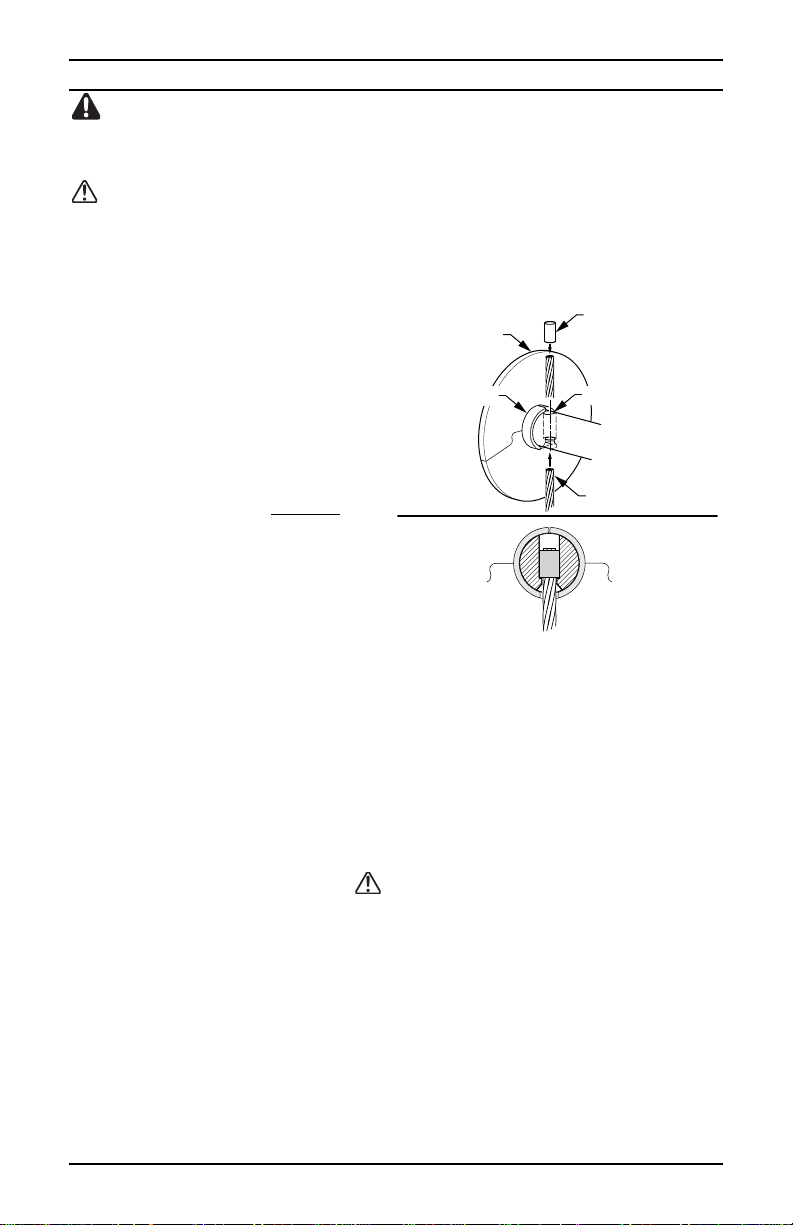
CABLE REPLACEMENT
WARNING ALWAYS USE THE EXACT POWERWINCH REPLACEMENT CABLE
(P/N P7188800AJ). WINCH RATING AND CABLE STRENGTH ARE MATCHED FOR SAFE
AND OPTIMUM PERFORMANCE
CAUTION ALWAYS WEAR LEATHER GLOVES WHEN HANDLING THE CABLE. STEEL
CABLE CAN CAUSE SERIOUS DAMAGE TO HANDS
1. Unplug the wire harness from the winch.
2. Loosen the clutch knob (turn counterclockwise) and pull the cable out completely.
3. Cut the old cable off
approximately 2" from the cable
drum.
4. Slide the collar away from the cable
then push the old cable out of the
drum shaft.
5. Insert the new cable through the
shaft. The cable must be inserted
through the side opposite the
counter bore.
6. Insert the stop sleeve over the
end of the cable until the cable is
flush with the end of the stop.
Solder or crimp the stop onto the
cable.
7. Pull the cable back through the shaft until the stop is seated in the counter bore of
hole.
8. Slide the collar around the cable. The notch on the collar fits around the cable.
9. Tighten the clutch control knob clockwise until finger tight to set the brake.
D
O NOT over tighten the clutch knob; over tightening can cause damage to
the clutch.
10. Reconnect the harness to the unit. Power-in the cable, keeping tension on the
cable as it is winding.
IF THE CABLE IS NOT WOUND CORRECTLY, IT MAY CAUSE LOSS OF POW ER AND RISK DA MAGE TO
THE LEVELWIND PLATE
UNWIND THE CABLE THEN REWIND WHILE KEEPING TENSION ON THE CABLE
. NEVER REPLACE THE CABLE WITH ROPE.
.
Stop Sleeve
Drum Flange
Drum Collar
Crimp or Solder
Over End of Cable
Counterbore
Stranded Cable
Completed Installation
pwRC013
CAUTION
. IF THE CA BLE IS NOT CORRECT (TOO LOOSE OR WOUND ON ONE SIDE),
.
9
Page 12

RC 23 & RC30 TRAILER WINCHES POWERWINCH
K
TROUBLESHOOTING GUIDE
WINCH DOES NOT OPERATE
A. Confirm power to winch
1. Check vehicle battery is fully charged
2. Confirm connections are for tight & clean.
3. Check wires are worn or bare that may
cause shorts
B. Check circuit breaker at battery
Bypass circuit breaker and test winch.
Does the winch run?
CAUTION Do not operate the winch
without the circuit breaker. Removing the CB
from the circuit is
ONLY for testing.
C. Check In-Line Fuse
A 5 amp in-line fuse is located under the top
cover of the winch. Refer to page 11.
NOTE: If fuse blows immediately when power is applied, disconnect power
cord from winch and battery. Check the polarity of the wiring in the
connector (refer to page 11). Correct as required.
LOAD SLIPS
A. Load slips during retrieval Thrust washers and thrust bearings
B. Load slips back after boat is retrieved Clutch bearing inside the 120 gear
C. Check clutch lining
The clutch lining is located on the 120
tooth gear under the LH (clutch side) of
the case. Ensure that the clutch is clean
free of grease.
EY FOB REMOTE DOES NOT OPERATE WINCH
For optimum performance, the remote should be operated within 10-15 feet
from winch. Refer to page 4 for additional information.
A. Check the remote battery
The battery must provide a minimum of 9V
to correctly transmit to the receiver.
B. Reprogram the remote/receiver
Follow the directions on page 4. YES Remote works
LIGHT WILL NOT TURN ON (Winch does operate)
A. Check the bulb
Refer to page 8 for access and
replacement information
B. Light does not turn on with switch but
works with remote
C. Light does not turn on with remote but
works with switch
10
Correct as required.
YES If winch runs, circuit
breaker is bad, replace.
NO Reconnect circuit breaker
and go to step C.
YES Fuse is good. Contact your
authorized service center.
NO Replace Fuse and test winch
operation.
are worn or deformed. Replace
has failed. Replace gear assy
Clean as required. If clutch lining is
worn or damaged, replace the 120
tooth gear assy.
YES Battery is good, go to step B.
NO Replace battery.
NO Transmitter or receiver is
defective. Contact your
authorized service center.
YES Bulb is good, go to step B.
NO Replace bulb
Switch is bad, replace
Check the remote. Refer
to page 4
Page 13

POWERWINCH RC 23 & RC30 TRAILER WINCHES
Replacing the In-Line Fuse
CAUTION
ALWAYS USE THE CORRECT RATED FUSE. USING THE WRONG FUSE CAN CAUSE THE
WINCH TO NOT OPERATE AND
An in-line fuse is located under the top cover of the unit. The in-line fuse is a
standard automotive AGC glass type fuse. Required rating is 5A, 250V. Fuses
are available at local automotive parts stores.
To access the fuse:
1. Disconnect the power cord
from the winch.
2. Remove the four (4) T-30 torx
drive screws that attach the top.
3. Lift the top up. Use care to not
break or damage the wires.
4. Locate the fuse holder and
open to inspect/replace the
fuse.
5. Test operation of the winch.
If the fuse blows when power is
applied, check the polarity of the
wires in the power cord
connector.
1. Disconnect the power cord
from the winch AND battery.
2. Test the continuity of the cable:
Using a continuity tester,
place one probe in the
negative terminal of the
connector. Touch the
second probe against the
vehicle frame.
3. If there is no continuity, remove
the cover from the plug.
4. The large diameter (8 ga) wire
goes to the gold terminal (+).
The small diameter (10 ga) wire
goes to the silver terminal (-).
If the connector is wired correctly (step 4), but there is no continuity (step 3), the
harness is defective and must be replaced.
/OR CAUSE DAMAGE TO THE ELECTRICAL COMPONENTS.
T-30 Torx Drive
Screw (qty: 4)
5A Fuse
Gold Terminal (+)
Large Dia.
(8 ga) Wire
Silver
Terminal (-)
Small Dia.
(10 ga) Wire
(Ground)
pwRC015
11
Page 14

RC 23 & RC30 TRAILER WINCHES POWERWINCH
ILLUSTRATED PARTS LIST
Cover and Electronics
17
16
1
15 (NLA)
13
14
17
11
10
18
1
19
12
8
12
2
4
3
5
6
1
7
9
pwRC501a
Page 15

POWERWINCH RC 23 & RC30 TRAILER WINCHES
Item RC23 RC30 Description Notes
1
R001333 R001311 Cover Kit
2
P5594700AJ P5594700AJ Hand Crank Handle
3
P7188800AJ P7188800AJ Replacement Cable
4
P7904300AJ P7904300AJ Pulley Block Kit
5
P7830201AJ P7830201AJ Wire Harness w/ items 6 & 7
6
P7810500AJ P7810500AJ Plug, Wire Harness
7
P7837300AJ P7837300AJ Circuit Breaker, 60amp
8
P7810300AJ P7810300AJ Power Socket
9
R001501 R001501 Key FOB Remote
10
R001499 R001500 Receiver Module 4
11
12
13
P55908 P55908 Bulb
14
R001312 R001312 Lens Replacement Kit
15
16
R001728 R001728 LED Light Kit 2
17
R001320 R001320 Switch, Light 3
18
R001287 R001295 Motor Assy
19
R001317 r001317 Solenoid
Notes 1. The in-line fuse is a standard automotive AGC glass type fuse.
2. Light Replacement Kit (item 15) with reflector, clips, bulb and lens
3. All items marked "17" are included in light switch kit.
4. The learn/override switch (item 12) is part of the receiver module
- Note 1 - Fuse, In-Line, 5A, 250V 1
- Note 4 - Switch, Learn/Override 4
- Note 2 - Light Replacement Kit 2
Required rating is 5A, 250V. Fuses are available at local
automotive parts stores.
kit is no longer available. Order LED Light kit (item 16)
(item 10)
13
Page 16

RC 23 & RC30 TRAILER WINCHES POWERWINCH
ILLUSTRATED PARTS LIST
Gear Assemblies
21
22
23
22
25*
26
23
25*
20
26
26
*
25*
24
* Items marked with astericks (*) are not used on RC23
14
pwRC502
Page 17

POWERWINCH RC 23 & RC30 TRAILER WINCHES
Item RC23 RC30 Description Notes
20
R001275 R001275 Level Wind Plate
21
R001314 R001314 Clutch Knob
22
P7160901 P7160901 Clutch Spring & Washer Kit 5
23
P91011 P91012 120T Stud and Gear Kit 6
24
P91007 P91007 Drum Shaft and Gear Kit 7
25
26
Notes 5. All items marked "21" are included in item 21 kit (clutch spring kit).
not used P91008 Intermediate Shaft and Gear Kit 8
P91010 P91009 Rear Shaft and Gear Kit 9
6. All items marked "22" are included in item 22 kit (120T stud and
gear kit).
7. All items marked "23" are included in item 23 kit (drum shaft and
gear kit).
8. All items marked "24" are included in item 24 kit (intermediate shaft
and gear kit).
9. All items marked "25" are included in item 25 kit (rear shaft and gear
kit).
15
Page 18

RC 23 & RC30 TRAILER WINCHES POWERWINCH
NOTES:
16
Page 19

POWERWINCH RC 23 & RC30 TRAILER WINCHES
WARRANTY
Carefree of Colorado (hereafter referred to as Carefree) warrants to the FIRST retail Purchaser that
the Powerwinch Product described in this manual is free of defects in material and workmanship
within the terms and conditions as set forth below. Carefree’s obligation under this warranty is
limited to the repair or replacement, at Carefree’s option, of any defective component within the
stated warranty period. T
1. D
URATION
a) 1 years on parts and labor.
b) Carefree will pay the transportation charges for return shipment to the purchaser of any
product received for legitimate warranty repair.
Warranty duration is not extended by the length of time the product is not in use or the time
that the purchaser is deprived the use of the product. The duration of coverage is determined
by the date of the original product purchase, not the date of repairs.
HAT IS COVERED UNDER THIS WARRANTY
2. W
Defects in the manufacturer’s material and workmanship of product under normal use, and
which occur within the duration of the warranty period.
HAT IS NOT COVERED UNDER THIS WARRANTY
3. W
a) Improper installation and/or any consequent damage or failure that results from improper
installation of the product.
b) Normal wear.
c) Conditions that are not related to the material or workmanship of the product: including
any failure that results from an accident, wind, rain, or other acts of God.
d) Purchaser’s abuse, including but not limited to neglect; failure to operate, use or maintain
the product in accordance with the instructions provided with the product.
e) Any component not sold or manufactured by Carefree.
f) Any failure that results from the use of another manufacturer’s product with a Carefree
product that is not specifically approved by Carefree.
g) Any incidental, indirect, or consequential loss, damage or expense that may result from
any defect, failure or malfunction of the product.
h) The removal or alteration of any product component or device. In the event of such
removal or alteration, this warranty is void.
i) Any expense related to delivery or pick-up of product to/from the service dealer.
ESPONSIBILITIES OF THE PURCHASER
4. R
N ORDER FOR THE WARRANTY TO BE HONORED, THE PURCHASER MUST HAVE PROOF OF
I
PURCHASE
WARRANTY CLAIM
. FAILURE TO PROVIDE THE REQUIRED DOCUMENTATION MAY DELAY OR VOID ANY
a) Retain dated proof of purchase for the product, and provide it as requested.
b) Perform “Periodic Maintenance” as specified in Owners Manual.
c) Use reasonable care in maintenance, operation, use and storage of the product in
accordance with the instructions contained in the owner’s manual.
HIS WARRANTY GIVES THE OWNER SPECIFIC LEGAL RIGHTS. THE LAWS OF CERTAIN JURISDICTIONS MAY
T
GRANT THE OWNER ADDITIONAL RIGHTS AND PRIVILEGES
no warranty, whether statutory or otherwise, including without limitation, any warranty of
merchantability or fitness for a particular purpose. Carefree shall have no liability except to repair,
replace or adjust defective products and parts. Carefree specifically excludes any liability, whether
in contract, tort or otherwise, for personal injury, property damage, economic or consequential
losses. Carefree has not authorized any person or company to alter the terms of this warranty.
It is Carefree of Colorado’s policy and practice to continuously improve the company’s products and
services. Therefore, Carefree reserves the right to make changes in design and components,
without notice, whenever it is believed the quality of the product will be improved, but without
incurring any obligation to incorporate such improvements in any product which has been shipped
or in service.
HIS WARRANTY IS NOT TRANSFERABLE.
.
. Except as set forth above; Carefree makes
17
Page 20

RC 23 & RC30 TRAILER WINCHES POWERWINCH
FOR YOUR RECORDS:
DEALER/INSTALLER
AME:
N
A
DDRESS:
PHONE:
PURCHASE DATE:
PART NUMBER:
SERIAL NUMBER:
PRODUCT NAME
OR DESCRIPTION:
Retain your original proof of purchase.
It is required for all warranty repairs and returns.
18
 Loading...