

Page 1

OWNER'S MANUAL
Capstan Powered Lift Assist
This Manual Provides Installation and Operation Instructions for the following models:
CAPSTAN 1000
C
APSTAN 300
UICK CATCH POT PULLER
Q
pwcs101
12 Volt Powered Winch
Powered Lift Assist for anchors, pots and traps.
These instructions apply to all models listed. Details and procedures unique to a
specific model are labeled appropriately.
056018-001 Printed in USA August, 2012
Page 2

PROPRIETARY STATEMENT
The Powerwinch Capstan is a product of Carefree of Colorad o, located in Broomfield,
Colorado, USA. The information contained in or disclosed in this document is
consideRED proprietary to Carefree of Colorado. Every effort has been made to ensure
that the information presented in the document is accurate and complete. However,
Carefree of Colorado assumes no liability for errors or for any damages that result from
the use of this document.
The information contained in this manual pertains to th e current configuration of the
models listed on the title page. Earlier model configurations may differ from the
information given. Carefree of Colorado reserves the right to cancel, change, alter or
add any parts and assemblies, described in this manual, without prior notice.
Carefree of Colorado agrees to allow the reproduction of this document for use with
Carefree of Colorado products only. Any other reproduction or translation of this
document in whole or part is strictly prohibited without prior written approval from
Carefree of Colorado.
TABLE OF CONTENTS
Safety Information ................................................................................... 1
General Safety Information ........................................................................... 1
Specifications .......................................................................................... 2
Furnished Materials: ...................................................................................... 3
Required Materials (not included with winch) ................................................ 3
Mounting the Unit .................................................................................... 4
Wiring the Unit ......................................................................................... 5
Testing the Unit ............................................................................................. 6
Operating the Winch ............................................................................... 7
Loading the Rope .......................................................................................... 7
Lowering the Load ......................................................................................... 7
Retrieving the Load ....................................................................................... 7
Maintenance .................................................................................................. 7
Replacement Parts List .......................................................................... 8
Warranty ................................................................................................. 10
Powerwinch 2145 W. 6th Avenue Broomfield, CO 80020
by Carefree of Colorado www.powerwinch.com
Page 3

POWERWINCH CAPSTAN POWERED LIFT ASSIST
SAFETY INFORMATION
WARNING A WARNING INDICATES A POTENTIALLY HAZARDOUS SITUATION WHICH,
IF NOT AVOIDED, COULD RESULT IN DEATH OR SERIOUS INJURY AND/OR MAJOR PROPERTY
DAMAGE
.
CAUTION A CAUTION INDICATES A POTENTIALLY HAZARDOUS SITUATION THAT
MAY CAUSE MINOR TO MODERATE PERSONAL INJURY AND
ALSO BE USED TO ALERT AGAINST UNSAFE PRACTICES
NOTE: A note indicates further information about a product, part, or step.
Tip: A tip provides helpful suggestions.
/OR PROPERTY DAMAGE. IT MAY
.
GENERAL SAFETY INFORMATION
The following Safety Precautions Must be Followed at ALL Times
Failure to follow the warnings and cautions in this manual could result in
serious injury and/or property damage.
Thoroughly read the manuals furnished with this prod uct and be familiar with the
controls. Do not allow individuals to operate the winch without understanding th e
safe operation and procedures for the equipment.
WARNINGS
ALWAYS unplug the wiring harness before attempting to install, relocate,
service or perform maintenance on the unit.
NEVER use the winch to lift or move people or animals.
NEVER use the winch for overhead lifting.
NEVER attempt to pull a load greater than the rated load of the winch.
NEVER use the winch to exclusively hold, support or permanently secure the
load. Use separate straps to support the load.
ALWAYS stand away from the winch during operation. ALWAYS stand clear of
the area behind and between the load or anchor point and the winch.
Serious injury could occur if the rope breaks.
ALWAYS keep hands clear of the drum area.
ALWAYS wear leather gloves when handling the rope.
NEVER wear loose fitting clothes, scarves, ties or jewelry when operating th e
winch. Loose clothing can become caught in moving parts.
ALWAYS tie off the anchor to a secure mount (e.g. a deck cleat) for storage
and after lowering the anchor. N
ALWAYS use the recommended rope.
EVER use the winch to tie off the anchor.
1
Page 4

CAPSTAN POWERED LIFT ASSIST POWERWINCH
SPECIFICATIONS
Davit/Bow Roller
This product requires the use of a closed loop davit or bow roller. Davit or bow roller
must be installed prior to installing inch to ensure proper performance.
CAUTION USE OF A DAVIT WITH AN OPEN LOOP IS NOT RECOMMENDED WITH THIS
PRODUCT
AND
* Recommended rope is three (3) strand, medium lay, premium nylon.
. USE A DAVIT WITH A CLOSED LOOP TO PREVENT SERIOUS PERSONAL INJURY
/OR PROPERTY DAMAGE.
6 7/16"
7 1/8"
Model
10 5/8"
Maximum
Pull Rope Size* Voltage
8 5/16"
Circuit
Breaker
pwcs004
Unit
Weight
Capstan 1000 1000 lbs. 1/2-3/4" 12VDC 80 amps 23 lbs.
Capstan 300 300 lbs. 1/2-5/8" 12VDC 25 amps 20 lbs.
Quick Catch Pot Puller 200 lbs. Up to 5/8" 12VDC 80 amps 19 lbs.
2
Page 5

POWERWINCH CAPSTAN POWERED LIFT ASSIST
FURNISHED MATERIALS:
Capstan 1000 Capstan 300 Quick Catch Pot Puller
qty Description qty Description qty Description
1 Winch 1 Winch 1 Winch
3 5/16-18 x 3.5 Stud 3 5/16-18 x 3.5 Stud 3 5/16-18 x 3.5 Stud
3 5/16 Lock W asher 3 5/16 Lock Washer 3 5/16 Lock Washer
3 5/16 F lat W asher 3 5/16 Flat Washer 3 5/16 Flat Washer
3 5/16-1 8 Nut 3 5/16-18 Nut 3 5/16-18 Nut
1 80A Circuit Breaker 1 25A Circuit Breaker 1 80A Circuit Breaker
1 Foot Switch 1 Foot Switch 1 Foot Switch
1 Mounting Template 1 Mounting Template 1 Mounting Template
REQUIRED MATERIALS (NOT INCLUDED WITH WINCH)
Loctite 242 thread locker or equivalent.
Silicone sealant.
LECTRICAL INSTALLATION – CAPSTAN 1000 & QUICK CATCH POT PULLER
E
These items are furnished by the installer.
Qty Description
6 awg RED Wire Class 105˚C Wire is used for the "run" wire from winch to
6 awg BLACK Wire Class 105˚C
7 5/16" 6 awg ring terminals
5 1/4-20 x 1/2 Screws Screws and nuts should be stainless
5 1/4-20 Nuts
a/r Wire ties
2 ft 1" diameter heat shrink
2 ft 2" diameter heat shrink
E
LECTRICAL INSTALLATION – CAPSTAN 300
These items are furnished by the installer.
Qty Description
8 awg RED Wire Class 105˚C wire is used for the "run" wire from winch to
8 awg BLACK Wire Class 105˚C
7 5/16" 8 awg ring terminals
5 1/4-20 x 1/2 Screws Screws and nuts should be stainless
5 1/4-20 Nuts
a/r Wire ties
2 ft 1" diameter heat shrink
2 ft 2" diameter heat shrink
switch, battery to sw itch and battery to winch.
Length is based on installation.
steel to avoid rust and corrosion.
switch, battery to sw itch and battery to winch.
Length is based on installation.
steel to avoid rust and corrosion.
3
Page 6

CAPSTAN POWERED LIFT ASSIST POWERWINCH
MOUNTING THE UNIT
P1053700AV Mounting Template
3/8" Hole Thru
Center Of Rope
Anchor Winch To Davit
Winch Mounting Hole
(3 Plcs)
3 1/2"
(88.9mm]
[139.7mm]
BOW OF BOAT
Drill 5/8" Hole for Foot Switch
(see text for location suggestions)
5 1/2"
6 7/8"
[174.6mm]
3 1/4"
[82.6mm]
5/16"
[7.9mm]
1/2" Hole Thru
Wire Harness
STERN OF BOAT
5/16" Mounting Stud
(x3)
Drill Holes as
Shown on Template
(4 total)
Mounting Template
Flat Washer
Centerline
of Davit/Bow Roller
Lock Washer
5/16" Nut
(x3)
1. Place the mounting template on the deck in the desired
location a nd secure
pwcs001
with tape.
a. The centerline of the capstan must line up with the centerline of the
davit or bow roller.
2. Drill the holes as marked on the template.
3. Remove the template.
4. Use a small amount of thread locker on t he end of the studs then thread the
5/16-18 x 3 1/2" studs into the winch. Hand tighten until snug.
5. Align the winch a nd the studs with the holes in the deck. Insert the wires
through the hole in the deck. Lower the winch to the deck.
6. Under the deck, secure the winch to the deck use one (1) each 5/16 flat
washer, 5/16 lock washer and 5/16 nut on each of the studs. Tighten the
nuts to secure the winch to the deck.
4
Page 7

POWERWINCH CAPSTAN POWERED LIFT ASSIST
WIRING THE UNIT
WARNINGS
ALWAYS disconnect the battery before working on electrical equipment.
ALWAYS use the recomme nded wire size and rated circuit breakers. Failure
to use the furnished and recommended sizes can cause a fire hazard and
void warranty.
When routing the wiring, avoid sources of heat.
When routing the wiring, avoid sharp edges that can cut or fray the wire
insulation.
1. Locate a suitable location for the switch.
Location should be easily accessible when handli ng the rope from the
capstan.
Locate the switch outside the normal traffic patterns. This is to avoid
the switch being accidently stepped on or tripped over.
2. Drill a 5/8" ho le through the mounting surface.
3. If attached, unscrew the rubber cap from the top of
the switch and install the switch from the underside of
the deck.
4. Fully thread the cap back onto the switch. Tighten the
jam nut from below deck to secure the switch.
5. Connect the two (2) red wires to the switch.
6. At the winch, terminate the wires from the winch with 5/16" ring terminals.
7. Route one BLACK wire from the winch to the battery location. Be sure to
allow adequate wiring to make connections, allow the wire to have some
slack when routing. Secure the wires with wire ties.
Tip: Before making the mechanical connection, slide a 2 1/2" piece of the
shrink tubing over one wire. Make the connection then slide the wrap over
the connection. Lightly heat the wrap until it shrinks around the terminals.
8. At the winch, terminate the BLACK wire with a 5/16" ring terminal. Attach the
new wire to the motor B
LACK wire with a 1/4 -20 screw and nut and shrink wrap.
9. At the battery, terminat e the BLACK wire with a 3/8" ring terminal. Attach the
new wire to the
NEGATIVE (-) terminal of the battery.
10. Route one RED wire from the winch to the switch location. Be sure to allo w
adequate wiring to make connections, allow the wire to have some slack
when routing. Secure the wire s with wire ties.
11. Terminate each end of the R
ED wire with 5/16" ring terminals.
12. Connect the motor GREEN wire to the RED wire with a 1/4 -20 screw and nut and
shrink wrap.
13. At the switch position, connect the R
ED wire to one of the short wires from switch
with a 1/4 -20 screw and nut and shrink wrap.
Switch Cap
5/8" Hole
Jam Nut
Switch
pwcs006
5
Page 8

CAPSTAN POWERED LIFT ASSIST POWERWINCH
14. Route one RED wire from the battery to the switch location. Be sure to
allow adequate wiring to make connections, allow the wire to have some
slack when routing. Secure the wires with wire ties.
15. At the switch terminate the new wire with a 5/16 ring terminal and attach to
the second short wire from the switch with a 1/4 -20 screw and nut and shrink
wrap.
16. At the battery terminate the R
ED wire with a #10 ring terminal. Attach the wire to
the "AUX" post of the circuit breaker.
17. Attach the circuit breaker to the
Circuit Breaker
Red
Foot Switch
*awg
POSITIVE (+) terminal of the battery.
awg
*awg
Green
Black
Red *
Black
Battery
Tape or
Heat Shrink
1/4-20 x 1/2
Screw & Nut
Ring Terminals
= Mechanical Connection
* Use 8awg wire for Capstan 300
Use 6awg wire for Capstan 1000
Use 6awg wire for Quick Catch Pot Puller
To Battery
(+12VDC)
Terminal
25A Circuit Breaker
(used w/ Capstan 300)
To Battery (+12VDC)
Terminal
80A Circuit Breaker
(used w/ Capstan 1000 &
Quick Catch Pot Puller)
Ring
Ring
Red
Wire
Red
Wire
pwcs005
TESTING THE UNIT
1. Ensure that all connections are secure and correct.
2. With no rope on capstan, press down the switch. If the motor runs but the
capstan does not turn, motor wires are reversed. Reverse the red and black
wires at the motor leads.
6
Page 9

POWERWINCH CAPSTAN POWERED LIFT ASSIST
OPERATING THE WINCH
The Capstan can be used to retrieve anchors, traps or pots; these are referred t o
as the "load" in the directions below.
LOADING THE ROPE
1. Thread the rop e throug h the davit or bow roller and pull back to the winch.
2. Wrap the rope counterclockwise 4-5 wraps around the capstan.
CAUTION ALWAYS SECURE THE ROPE TO A DECK CLEAT OR SIMILAR DEVICE. DO
NOT USE THE WINCH TO TIE OFF THE LOAD.
CAUTION ALWAYS USE THE RECOMMENDED ROPE (SEE PAGE 2). USE OF
DIFFERENT ROPE CAN CAUSE PROPERTY DAMAGE AND PERSONAL INJURY
LOWERING THE LOAD
1. Turn boat into wind and place boat motors in neutral.
2. After the boat has stopped a ll forward progress, release the rope from the
deck cleat. Allow the load to free fall to the sea bed.
CAUTION NEVER USE THE WINCH TO LOWER THE LOAD OR TO BRAKE THE LOAD
DURING FREE FALL
3. After the desired amount of rope has been released, tie the rope off to a
deck cleat. D
4. For anchors, place the boat's motors in n eutral and allow the boat to drift
back and set the anchor in the sea bed.
. THIS CAN RESULT IN SERIOUS DAMAGE TO THE GEAR TRAIN.
O NOT use the winch to tie-off the anchor.
RETRIEVING THE LOAD
1. Untie the rope from the deck cleat.
2. Align bow of boat with load.
3. Place the boat's motors in forward and
move boat slowly toward the anchor
Pull Rope Hand over
Hand While Pressing
the Foot Switch
point.
4. Press the winch switch and pull the
rope hand over hand.
NOTE: The rope must be kept under
tension for the winch to work properly.
Foot Switch
5. After the load is secured, tie the
rope off to a deck cleat. D
O NOT
use the winch to tie-off the load.
MAINTENANCE
Following each boat outing, flush exterior of winch with fresh water. Use only
mild detergents to clean exterior. Use of solvents can cause damage to the
finishes and seals, as well as void product warranty
Every 6 months inspect capstan for wear. Replace any worn components.
Check rope periodically for abrasion or deep cuts. Never splice an ol d rope with a new
rope. If replacement is necessary, use only Powerwinch recommended rope.
Check electrical connections every 6 months for corrosion. Replace any
connection or wire which is damaged, corroded, frayed or worn.
.
Wrap Rope
4-5 Times
Counterclockwise
pwcs002
7
Page 10
CAPSTAN POWERED LIFT ASSIST POWERWINCH
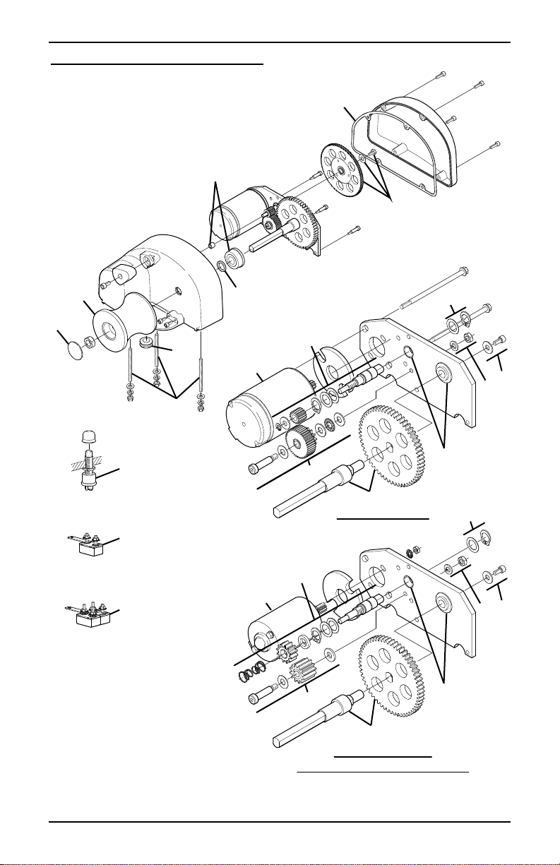
REPLACEMENT PARTS LIST
1
7
12,13
3
1
1
2
5
6
7
1
12
8
10
9
CAPSTAN 1000
13
8
11
12
7
7
13
11
10
9
9
9
CAPSTAN 300 &
QUICK CATCH POT PULLER
8
Page 11

POWERWINCH CAPSTAN POWERED LIFT ASSIST
Item Description Capstan
1000
1
Sea l & G a s k e t K i t P10346 P10346 P10346
2
Mounting Kit P10728 P10728 P10728
3
Capstan Kit R001461 R001461 R001461 1
4
Foo t S w i t c h P7817600AJ P7817600AJ P7817600AJ
5
Cir c u it Bre a k e r , 2 5 A -- P1027600AJ --
6
Cir c u i t B r e a k er, 80 A P1066800AJ -- P1066800AJ
7
Bearing Kit P10725 P10343 P10343
8
Motor Kit R001462 R001451 R001463
9
Capstan Shaft R001456 R001456 R001456
10
Locking Gear Kit P10731 -- --
11
Locking Gear Kit -- R001453 R001453
12
Intermediate Shaft P10723
13
Intermediate Shaft -- R001446 R001446
Capstan
300
Quick Catch
Pot Puller
Notes
Notes: 1. Capstan kit (item 3) includes seal and nut.
FOR YOUR RECORDS:
DEALER/INSTALLER
PURCHASE DATE:
PART NUMBER:
SERIAL NUMBER:
PRODUCT NAME
OR DESCRIPTION:
AME:
N
A
DDRESS:
PHONE:
Retain your original proof of purchase.
It is requi
RED for all warranty repairs and returns.
9
Page 12

CAPSTAN POWERED LIFT ASSIST POWERWINCH
WARRANTY
Carefree of Colorado (hereafter referred to as Carefree) warrants to the FIRST retail Purchaser that
the Powerwinch Product described in this manual is free of defects in material and workmanship
within the terms and conditions as set forth below. Carefree’s obligation under this warranty is
limited to the repair or replacement, at Carefree’s option, of any defective component within the
stated warranty period. T
1. D
URATION
a) 2 years on parts and labor.
b) Carefree will pay the transportation charges for return shipment to the purchaser of any
product received for legitimate warranty repair.
Warranty duration is not extended by the length of time the product is not in use or the time
that the purchaser is deprived the use of the product. The duration of coverage is determined
by the date of the original product purchase, not the date of repairs.
HAT IS COVERED UNDER THIS WARRANTY
2. W
Defects in the manufacturer’s material and workmanship of product under normal use, and
which occur within the duration of the warranty period.
HAT IS NOT COVERED UNDER THIS WARRANTY
3. W
a) Improper installation and/or any consequent damage or failure that results from improper
installation of the product.
b) Normal wear.
c) Conditions that are not related to the material or workmanship of the product: including
any failure that results from an accident, wind, rain, or other acts of God.
d) Purchaser’s abuse, including but not limited to neglect; failure to operate, use or maintain
the product in accordance with the instructions provided with the product.
e) Any component not sold or manufactured by Carefree.
f) Any failure that results from the use of another manufacturer’s product with a Carefree
product that is not specifically approved by Carefree.
g) Any incidental, indirect, or consequential loss, damage or expense that may result from
any defect, failure or malfunction of the product.
h) The removal or alteration of any product component or device. In the event of such
removal or alteration, this warranty is void.
i) Any expense related to delivery or pick-up of product to/from the service dealer.
ESPONSIBILITIES OF THE PURCHASER
4. R
N ORDER FOR THE WARRANTY TO BE HONORED, THE PURCHASER MUST HAVE PROOF OF
I
PURCHASE
WARRANTY CLAIM
. FAILURE TO PROVIDE THE REQUIRED DOCUMENTATION MAY DELAY OR VOID ANY
a) Retain dated proof of purchase for the product, and provide it as requested.
b) Perform “Periodic Maintenance” as specified in Owners Manual.
c) Use reasonable care in maintenance, operation, use and storage of the product in
accordance with the instructions contained in the owner’s manual.
HIS WARRANTY GIVES THE OWNER SPECIFIC LEGAL RIGHTS. THE LAWS OF CERTAIN JURISDICTIONS MAY
T
GRANT THE OWNER ADDITIONAL RIGHTS AND PRIVILEGES
no warranty, whether statutory or otherwise, including without limitation, any warranty of
merchantability or fitness for a particular purpose. Carefree shall have no liability except to repair,
replace or adjust defective products and parts. Carefree specifically excludes any liability, whether
in contract, tort or otherwise, for personal injury, property damage, economic or consequential
losses. Carefree has not authorized any person or company to alter the terms of this warranty.
It is Carefree of Colorado’s policy and practice to continuously improve the company’s products and
services. Therefore, Carefree reserves the right to make changes in design and components,
without notice, whenever it is believed the quality of the product will be improved, but without
incurring any obligation to incorporate such improvements in any product which has been shipped
or in service.
HIS WARRANTY IS NOT TRANSFERABLE.
.
. Except as set forth above; Carefree makes
10
 Loading...