

Page 1
Operating Instructions and Replacement Parts List Deckmate 25 Freefall Pontoon Windlass
Please read and save these instructions. Read carefully before attempting to assemble, install, operate or
maintain the product described. Protect yourself and others by observing all safety information. Failure to
comply with instructions could result in personal injury and/or property damage! Retain instructions for
future reference.
Deckmate 25 Free Fall
PontoonWindlass
Featuring patented
“free fall release
system” & over-
sized davit roller for
smooth hands free
operation
Description
The Deckmate 25 Free Fall Pontoon Windlass assists in the launching and retrieving of a “mushroom” or
“river” style anchor typically used on pontoon boats. This windlass has the capacity to lift up to a fi fty pound
anchor and the patented free fall feature gives it the ability to drop and set the anchor in a fraction of the time
that it takes a traditional power down windlass. The built in light assists retrieving anchors and launching or
retrieving the boat at night.
Unpacking
When unpacking, inspect carefully for any damage that may have occurred during transit. Make sure any loose
fi ttings, bolts, etc.., are tightened before putting unit into service.
General Safety Information
Throughout this manual potential safety hazards will be noted with the following terms. Please read and
understand these terms before operating the product.
Danger means a hazard that
will cause death or serious injury if the warning is ignored.
© 2006 Powerwinch
Warning means a hazard that
cause death or serious
could
injury if the warning is ignored.
Caution means a hazard that
may cause minor or moderate
injury if the warning is ignored.
It also may mean a hazard that
will only cause damage to property
P4405401AV 12/06
Page 2

Operating Instructions and Replacement Parts List Deckmate 25 Freefall Pontoon Windlass
Rope breakage and
whiplash hazard.
1. Never stand between the load point and the
winch. If the rope breaks it could snap back with
enough force to cause severe injury or death.
2. The winch is shipped with a closed loop
anchor roller. If the included anchor roller is
ever replaced it must be replaced by a closed loop
anchor roller. The closed loop anchor roller will
prevent the anchor line from snapping onto the
boat deck in the event the rope breaks.
3. Always use nylon rope specifically rated for
this product. Never substitute cable for rope.
Cable is not an acceptable anchor line because
it does not stretch and is easily frayed. If cable
breaks it can snap back with more force than
nylon rope.
4. This product is intended to lift only river &
mushroom anchors. Do not attempt to lift or
move people or other objects with this winch.
Cruising and boat
trailering hazards.
1. When the boat is cruising or being trailered, the
anchor must be tied to a cleat (or other secure point)
or secured with a safety chain/strap. If the anchor
breaks free during cruising or trailering, it will cause
serious damage and/or injury.
Anchoring hazards.
1. Always tie the anchor line off to a cleat (or other
secure point) when the boat is anchored. The winch
must not be used to hold the load of the boat while
anchored. Serious damage to the motor and/or
failure of the winch could occur.
2. Do not pull a load greater than the rating for the
winch. If the circuit breaker halts operation of the
winch during retrieval or deployment, the winch
may have been overloaded. Stop using winch until
the cause of the problem has been determimed.
5. Inspect entire rope for weak or worn condition
or kinking (short tight twist or curl) before
each use. Replace worn rope with nylon rope
specifically rated for this product.
Electrical shock and
fire hazards.
1. Do not use electrical wire sizes other than
those specified in this manual. Using wire that is
too small could result in overloading and a fire.
2. Use only the supplied or recommended circuit
breakers when installing this winch. Using
incorrect circuit breakers could result in a fire.
3. Use only marine grade, fully tinned wire for
electrical connections between the battery and the
winch.
4. Make sure any crimped electrical connectors
meet can withstand a 25 lb pullout force before
failing.
5. Always disconnect the wiring harness from the
battery before attempting to install, relocate, or
service the winch or switch.
Entanglement
hazards.
1. Never place any object or tool in the rope
spool while retrieving or deploying the anchor.
The tool or object could become tangled in the
rope resulting in serious injury and/or damage to
the winch.
2. Do not wear loose fitting clothing, scarves,
or neck ties during the operation of the winch.
Loose clothing may become caught in moving
parts resulting in injury or death.
3. Do not operate the winch under the influence
of drugs and/or alcohol.
Operation hazards
1. It is always best to make sure that the windlass
is visible while under operating conditions. If
the rope should become “tangled” or “caught
up” while retrieving or deployment of the anchor
then the operator will be able to quickly turn the
windlass off before damage can occur.
2
Page 3
Operating Instructions and Replacement Parts List Deckmate 25 Free Fall Pontoon Windlass
Deckmate 25 Freefall Pontoon Windlass Product and Performance Specifications
Maximum Line Size, Average Line Motor Circuit Unit
Anchor Type, and No Load Speed With Operating Breaker Unit Dimensions
Model Weight Length Line Speed 50 lb. Anchor
Deckmate 25 50 lbs 3/16” dia
Nylon,
100’ long
85 ft/min 33 ft/min 12V DC 25 amps 15 lbs. 12.25x8.5x8.25
Voltage Rating Weight (LxWxH)
Deckmate 25 Installation
IMPORTANT: REVIEW THESE INSTALLATION INSTRUCTIONS BEFORE INSTALLING!
There are 5 steps to installing the Deckmate 25 that must be completed in the order below for proper installation:
1. Assembling, locating, and installing the bow roller.
2. Locating and installing the winch mechanism.
3. Deciding location for switch (on the winch or at the helm).
4. Installing the switch and wiring the winch to the battery.
5. Assembling the cover and unit test.
STEP 1. Assembling, locating and installing the bow roller.
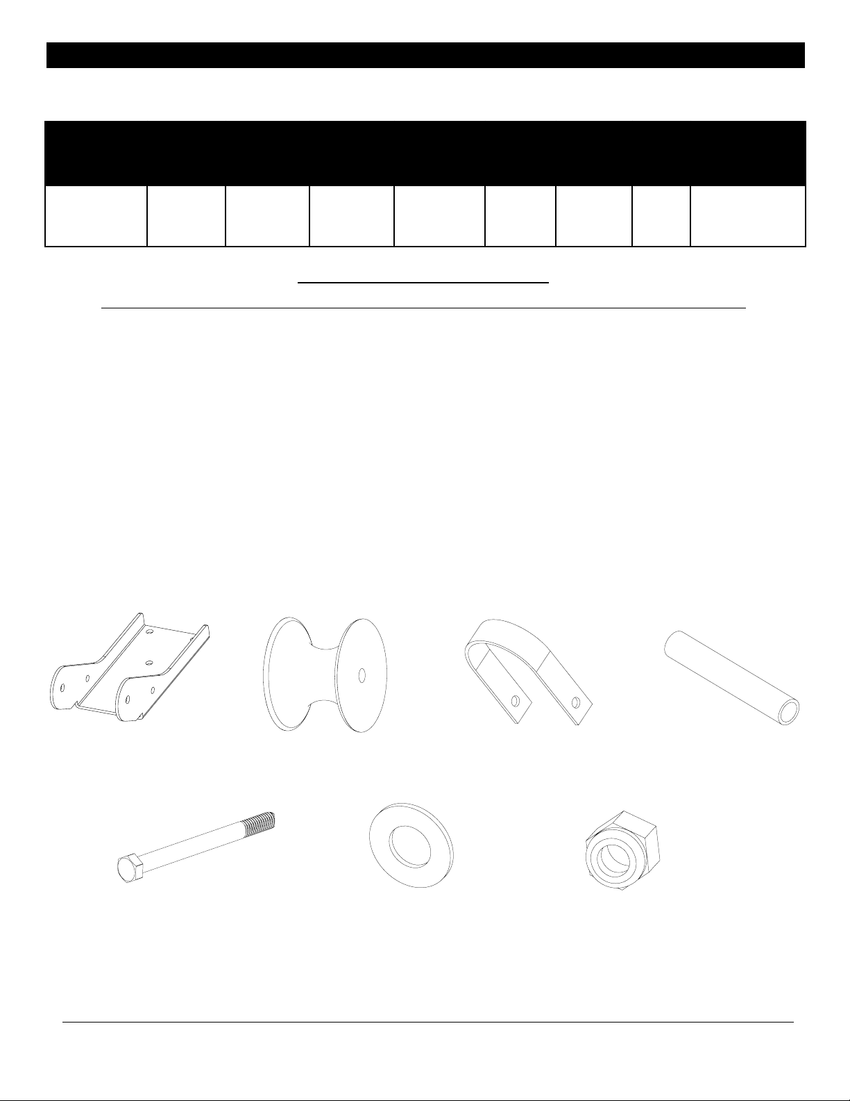
The bow roller comes unassembled in the packaging with the windlass. Locate the parts shown below before starting the assembly:
P10951 BOW ROLLER HOUSING P55710 ROLLER P55715 BOW ROLLER LOOP
P55712 BOW ROLLER SPACER
P55703 ROLLER BOLT STO70932AV WASHER P55704 HEX NUT
3
Page 4
Operating Instructions and Replacement Parts List Deckmate 25 Free Fall Pontoon Windlass
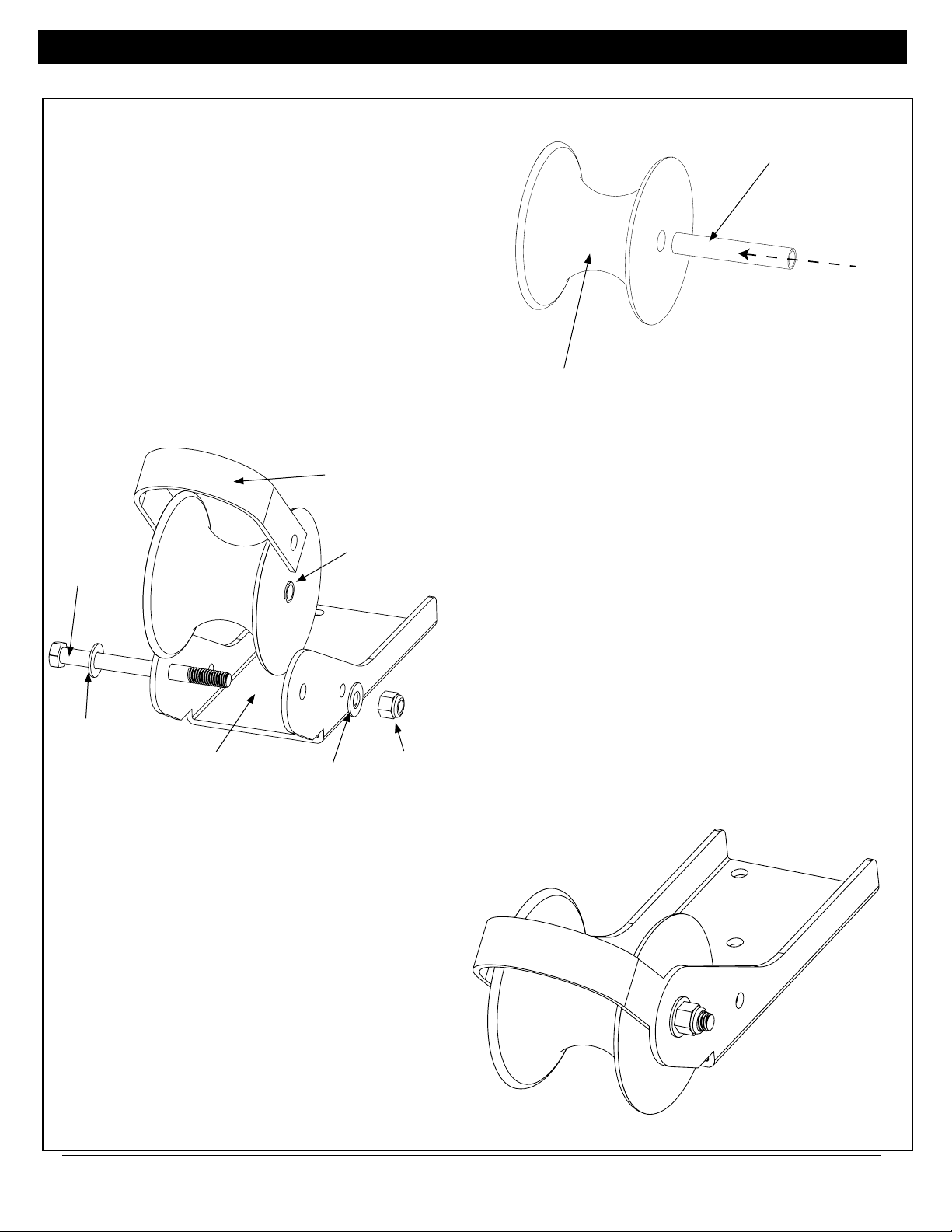
STEP 1. Assembling, locating and installing the bow roller. (Continuted)
P55712 BOW ROLLER SPACER
- Insert P55712 Bow Roller Spacer into P55710 as
shown in Figure 1.
INSERT SPACER
INTO HOLE IN
BOW ROLLER AS
SHOWN
P55710 ROLLER
FIGURE 1. ASSEMBLING SPACER INTO ROLLER
P55715 BOW
ROLLER LOOP
P55703
ROLLER
BOLT
ST070932AV
WASHER
FIGURE 2. ASSEMBLING ROLLER INTO HOUSING
P10951 BOW
ROLLER
HOUSING
ST070932AV
WASHER
ROLLER AND
SPACER
P55704
HEX NUT
- Insert bow roller and spacer into P10951 Bow Roller
Housing along with P55715 Bow Roller Loop as shown
in Figure 2. Make sure that the loop fi ts inside the bow
roller housing, not outside. Secure with P55703 Roller
Bolt, STO70932AV Washers (one per side) and P55704
Hex Nut. The completely assembled bow roller is shown
in Figure 3.
FIGURE 3. COMPLETELY ASSEMBED BOW ROLLER
4
Page 5
Operating Instructions and Replacement Parts List Deckmate 25 Free Fall Pontoon Windlass
CC
LL
CC
LL
STEP 1. Continued
With the bow roller assembled, it can now be located
on the bow of the boat.
!!IMPORTANT!!
Before drilling any holes, make sure the bow
roller extends over the bow or side of the boat far
enough so that the anchor will not hit the boat
when being retrieved or deployed.
Locate the bow roller and mark the three holes in
the bow roller on the deck of the boat. Using a 1/4”
diameter drill bit, drill the holes through the deck.
Using three of the 1/4-20 x 3.0 long screws in the
kit (along with three lock washers, flat washers, and
nuts), secure the bow roller to the deck as shown in
Figure 4.
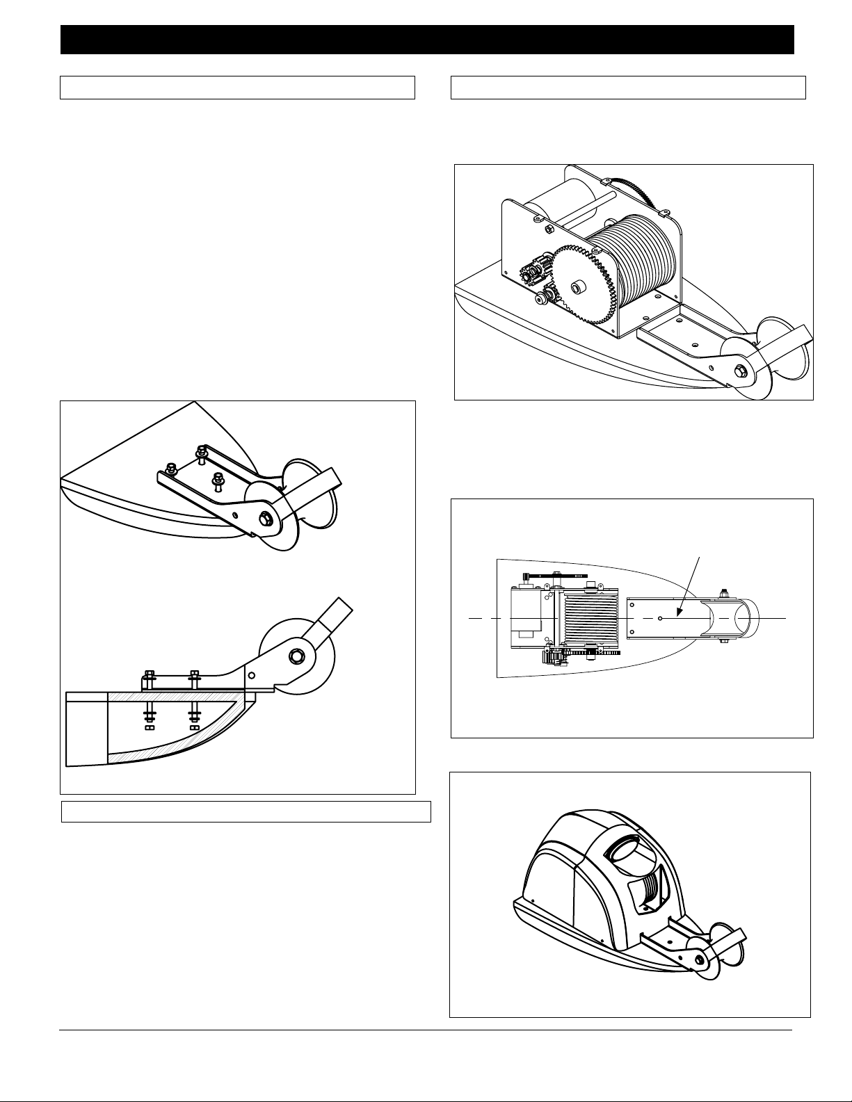
STEP 2. Continued
Remove the winch mechanism from the box and
locate behind the bow roller on the deck of the boat
as shown in Figure 5.
FIGURE 5.
Location of winch
mechanism on
bow of boat
Make sure the centerline of the rope spool is in line
with the center line of the bow roller as shown in
Figure 6. If the winch is not properly aligned with
the bow roller, the winch will not operate properly.
FIGURE 4
Bow roller assembly assembled to bow of boat
Cut-away view
Step 2. Locating and installing winch mechanism
!!IMPORTANT!!
BEFORE DRILLING HOLES TO MOUNT
WINCH MECHANSIM, MAKE SURE THERE
IS ENOUGH SPACE BETWEEN THE BOW
ROLLER AND THE WINCH COVER TO
PREVENT THE ANCHOR FROM HITTING
THE COVER WHEN THE ANCHOR IS RETRIEVED.
Centerline of bow roller must
line up with center line of rope
spool on winch
Figure 6.
Aligning winch rope
spool to bow roller
Remove cover from box and place over winch as
shown in Figure 7.
Figure 7. Winch cover
placed over winch
mechanism.
5
Page 6

Operating Instructions and Replacement Parts List Deckmate 25 Free Fall Pontoon Windlass
S
E
S
D
H
R
G
STEP 2. Continued
Place the anchor in the bow roller and make sure the
shank of the anchor does not touch the winch cover
when the anchor is seated in the bow roller. See
Figure 8.
Figure 8. Anchor shank
clearance check
MMAAKKEESSUURRE
AANNCCHHOORRSSHHAANNKKFFIITTS
IINNTTHHIISSAARREEAAAANND
DDOOEESSNNOOTTTTOOUUCCH
TTHHEEWWIINNCCHHCCOOVVEER
BBEEFFOORREEDDRRIILLLLIINNG
MMOOUUNNTTIINNGGHHOOLLEES
Once it is certain the anchor will not hit the cover
of the winch, remove the cover. Using a permanent
marker, mark the deck through the mounting holes
in the winch frame. Figure 9 shows which holes in
the winch frame should be used as mounting holes.
Figure 9. Locating
mounting holes.
Use these 3 holes in
the winch frame as
guides for mounting
holes
STEP 2. Continued
Wiring Harness Hole:
A hole in the deck is needed to pass the wiring har-
ness from the battery though to the winch. Locate the
template at the end of this manual and place it on the
deck. Line up the mounting holes on the template with
the mounting holes that were just drilled on the deck.
Find the hole on the template for the wiring harness and
mark it on the deck. Remove the template and drill the
hole with a 5/8” drill bit.
With all the mounting holes drilled, secure the winch
to the boat deck using the fasteners included in the kit.
Refer to Figure 10 for proper assembly of the fasteners.
Figure 10. Location of mounting fasteners
1/4”-20 Hex Head
Screw
1/4” Flat
Washer
1/4” Flat
Washer
1/4” Lock
Washer
1/4” Hex
Nut
Cut Away View of Winch on Deck
Step 3. Deciding Location of Switch
The Deckmate 25 has the capability of having the
switch mounted on the winch cover or at the helm of
the boat. Some items to consider about the location of
the switch:
After marking the holes as shown, remove the
winch and drill the holes through the deck using a
1/4” drill bit.
1. Locating the switch on the helm will allow the boat
to be steered torward the anchor point when the winch
is being used.
2. Locating the switch on the helm will require extra
wiring for the light to be operational.
3. Locating the switch on the helm will require a
switch cover plate to be installed on the winch cover.
This cover plate is included with the winch kit.
Step 4. Installing the switch and wiring the winch to the
battery.
To install the switch on the helm, go to Page 7. To install the switch on the winch cover, go to Page 9.
6
Page 7

Operating Instructions and Replacement Parts List Deckmate 25 Free Fall Pontoon Windlass
"
"
Step 4. Installing the switch and wiring the winch to the
battery. (continued).
Installing The Switch On The Helm
1. Find a suitable location to install switch. Make sure
there is enough room behind the switch mounting location for the switch and wiring to the switch.
2. Cut a rectangular hole that is 1 7/8” wide by 1 5/8”
high. Refer to Figure 11.
Figure 11. Size Of Switch Mounting Hole
Step 4. Installing the switch and wiring the winch to the
battery. (continued).
1177//88"
1155//88"
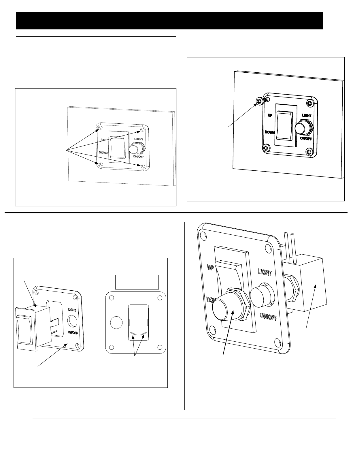
3. Locate rocker switch in parts pack and assemble
into switch plate as shown in Figure 12.
Figure 12. Switch Plate Assembly
Rocker Switch
Switch Plate
4. Locate push button switch for light and rubber
boot that fi ts over switch and assemble as shown in
Figure 13.
Top of Switch
Plate
Rear view of switch.
Make sure angled
terminals are located
as shown.
Switch Boot
Figure 13. Light Switch Assembly.
Insert push button switch through hole in switch
plate and secure with switch boot.
5. Locate the switch cover plate in the parts pack
and the four screws needed to secure the plate to the
winch cover. Assemble the switch cover plate as
shown in Figure 14.
Figure 14. Switch Cover Plate Assembly
Switch Cover Screw
(Qty of 4)
Switch Cover Plate
(Qty of 4)
Push Button
Switch
7
Page 8
Operating Instructions and Replacement Parts List Deskmate 25 Free Fall Pontoon Windlass
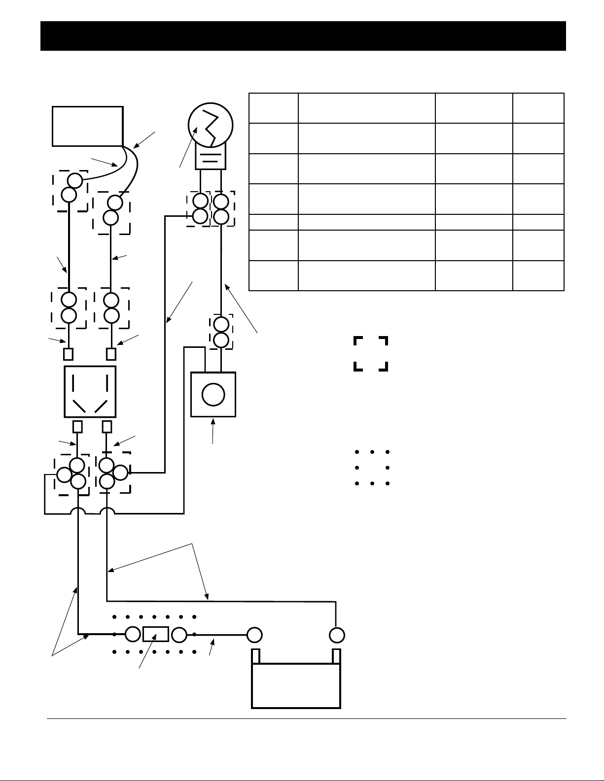
6. Refer to Figure 15 for the wiring needed between the winch, switch and battery. The kit contains all
the parts needed to complete the wiring.
Winch
Motor
GreenWire
F
C
8 GA
Red
Wire
C
D
D
CC
F
C
C
F
Black
Wire
Light In
Winch
Cover
8 GA
Black
Wire
E
Winch
Switch
(rear
view)
E
F
F
12 GA
Black
Wire
F
Push Button
Light Switch
8 GA
Black Wire
Symbol Description Part Number Quantity
in Kit
A 3/8” ring terminal for 8
gage wire
B #10 ring terminal for 8
gage wire
C 5/16” ring terminal for 8
gage wire
D Red switch wire assembly P44071 2
E Black switch wire assem-
bly
F 5/16” ring terminal for
10-12 gage wire
NOTES:
12 GA
Red
Wire
Denotes the ring terminals inside
the box should be connected
together with a 1/4-20 bolt and
nut inclueded in the kit. The
connection should then be sealed
with 1” diameter heat shrink tubing included in the kit.
Denotes the circuit breaker
should be sealed with the 2”
diameter heat shrink tubing included in the kit after it has been
connected to the wiring from the
winch and battery
P55801 2
ST072730AV 2
ST072732AV 6
P44072 2
ST072726AV 6
8 GA
Red Wire
B
Circuit
Breaker
(25A)
B
8 GA
Red Wire
Minimum
12” Long
A
+
12 Volt DC
Battery
A
Figure 15.
Wiring Diagram for
-
8
Mounting Switch on
Helm
Page 9
Operating Instructions and Replacement Parts List Deskmate 25 Free Fall Pontoon Windlass
Step 4. Installing the switch and wiring the winch to the
battery. (continued).
7. After the wiring has been installed as shown in Figure 15, place the switch plate assembly into the hole cut
in the panel and mark the holes for the switch plate as
shown in Figure 16. Drill pilot holes with a 1/8” drill
bit
Figure 16. Switch Plate Assembly
Mark these
holes and drill
through with a
1/8” drill bit
8. Secure switch plate to helm using screws supplied in
kit at shown in Figure 17.
Secure switch
plate using
screws in kit
Figure 17. Securing switch plate to helm
Installing The Switch On The Winch Cover
1. Locate rocker switch in parts pack and assemble
into switch plate as shown in Figure 16.
Figure 16. Switch Plate Assembly
Rocker Switch
Top of Switch
Plate
Rear view of switch.
Switch Plate
Make sure angled
terminals are located
as shown.
2. Locate push button switch for light and rubber
boot that fi ts over switch and assemble as shown in
Figure 17.
Push Button
Switch
Switch Boot
Figure 17. Light Switch Assembly.
Insert push button switch through hole in switch
plate and secure with switch boot.
9
Page 10
Operating Instructions and Replacement Parts List Deskmate 25 Free Fall Pontoon Windlass
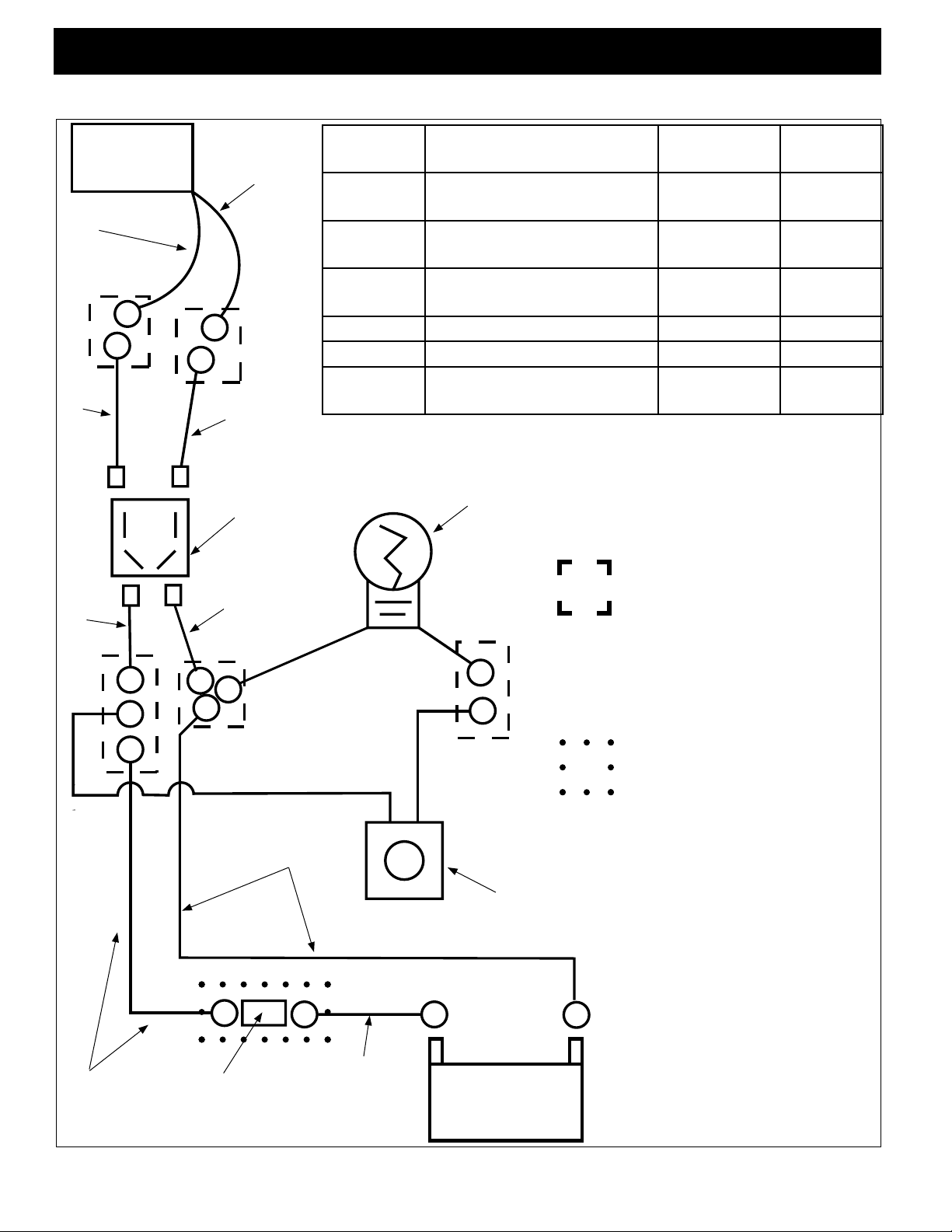
3. Refer to Figure 18 for the wiring needed between the winch, switch and battery. The kit contains all
the parts needed to complete the wiring.
Green
Wire
D
D
Winch
Motor
F
Black
Wire
F
E
Winch Switch
(rear view)
E
C
Symbol Description Part Number Quantity in
Kit
A 3/8” ring terminal for 8
gage wire
B #10 ring terminal for 8 gage
wire
C 5/16” ring terminal for 8
gage wire
D Red switch wire assembly P44071 2
E Black switch wire assembly P44072 2
F 5/16” ring terminal for 10-
12 gage wire
Light In
Winch Cover
NOTES:
Denotes the ring terminals inside
the box should be connected
together with a 1/4-20 bolt and
nut inclueded in the kit. The
connection should then be sealed
with 1” diameter heat shrink tubing included in the kit.
P55801 2
ST072730AV 2
ST072732AV 6
ST072726AV 6
8 GA
Red Wire
C
Circuit
Breaker
(25A)
Black Wire
B
8 GA
BA
8 GA
Red Wire
Minimum
12” Long
+
12 Volt DC
Battery
10
Push Button
Light Switch
A
-
Denotes the circuit breaker
should be sealed with the 2”
diameter heat shrink tubing included in the kit after it has been
connected to the wiring from the
winch and battery
Figure 18.
Wiring Diagram for
Mounting Switch on
Winch Cover
Page 11

Operating Instructions and Replacement Parts List Deskmate 25 Free Fall Pontoon Windlass
Step 5. Assembling Winch Cover and Unit Test
1. Before securing cover to winch frame, make sure all
wiring from the switchs, light, and battery are clear of
the winch gears. Wire ties may be used to secure these
wires to the winch frame.
2. Locate the cover mounting bars (4 total, 2 per side)
and cover mounting screws in the winch parts pack.
3. The winch cover screws pass through the cover and
the cover mounting bars to thread into the winch frame
as shown in Figure 19.
Figure 19. Assembling Winch Cover
Step 5. Assembling Winch Cover and Unit Test
Unit T est
1. Make sure area around winch is clear of all people
and objects.
2. Press the rocker switch in the down position and
hold for 5 seconds. The motor will reverse the gear
train and the winch is now in free-fall mode.
3. Release switch and pull approximately three feet
of rope out of the winch.
4. Now press rocker switch in the up position and
hold. The winch will now reverse direction and pull
rope back into winch.
5. Press light push button switch in once and the
light should illuminate. Press switch in again and the
light should go out.
Cover
Screws
Cover
Mounting
Bar
4. If you are mounting the switch to the winch cover,
locate the four screws that are needed to secure the
switch plate in Figure 17 and assemble them as shown
in Figure 20.
Secure switch
plate using
screws in kit
Figure 20. Securing switch plate to winch cover
11
Page 12
Operating Instructions and Replacement Parts List Deckmate 25 Freefall Pontoon Windlass
Recommended Operating Procedures
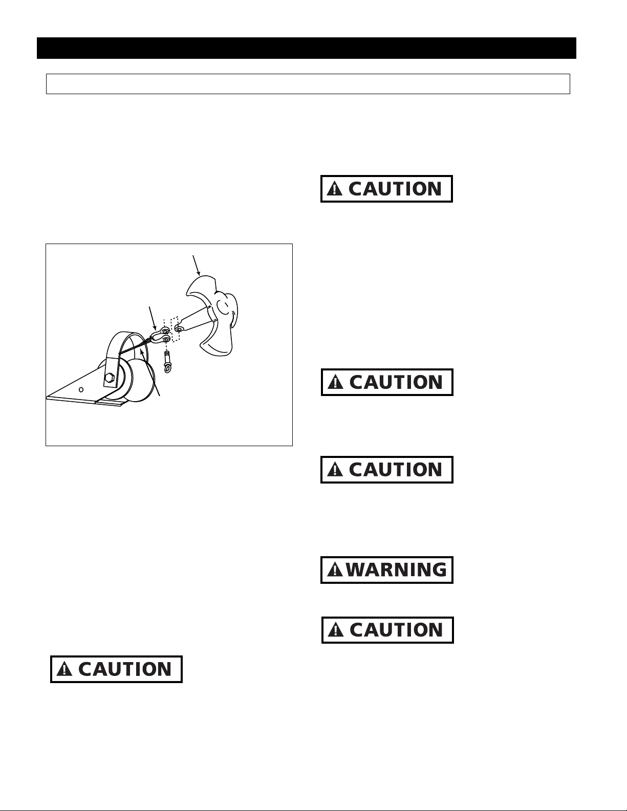
Attaching the Anchor
Note: Powerwinch recommends using a shackle
to attach the anchor to the anchor line.
1. Locate the loop at the end of the anchor line on
the spool.
2. Pass the shackle through this loop and then
secure the anchor by passing the shackle pin
throgh the anchor shank line. Securely tighten the
shackle pin. See Figure 21 for reference.
ANCHOR
SHACKLE
LOOP IN
ROPE
Figure 21. Anchor Attachment
Deploying The Anchor
1. Once an anchoring spot has been located and
the depth of the water is estimated, the anchor can
be dropped.
2. Turn the the boat into the wind and put the motor in neutral.
3. Once the boat has stopped all forward progress,
press the switch in the down position and hold for
5 seconds.
4. The anchor will release from the bow roller
and free-fall into the water. Once the anchor has
stopped free-falling, reverse the motors on the
boat and pull out as much rope as needed to safely
anchor.
Always wait for the
anchor to stop falling before retrieving the anchor line. Retrieving the anchor line while in free-fall will damage the winch and void your warranty.
5. Once the desired amount of rope has been
let out, Press the switch in the up position and
retrieve approximately 3 feet of line. This will
lock the winch and prevent any more line from
paying out.
Always tie the line
off to a cleat when
anchored. Do not use the winch to solely hold
the load of the anchor line.
Retrieving the Anchor
1. Untie the anchor line from the cleat.
2. Align the boat with the anchor line.
3. Engage boat motor and slowly begin to move
torward the anchor.
4. Press the winch switch in the up position and
hold to pull the anchor line in.
Never use the winch
to solely move the
boat toward the anchor. Always slowly move
torward the anchor using the boat motor.
5. Once the anchor is out of the water, jog the
switch to get the anchor up into the bow roller.
Never slam the
anchor into the bow
roller. This will cause damage to the winch
and may prevent the anchor from free-falling
on the next anchor deployment.
6. Once the anchor has been pulled into the bow
roller, always tie the anchor off to a cleat.
Always tie off the
anchor to a cleat
after retreival. This will prevent the anchor
from breaking free in transit.
Never use the wind-
lass to break a stuck
anchor free. This may overload the windlass
and cause damage to the gear train.
12
Page 13
Operating Instructions and Replacement Parts List Deckmate 25 Freefall Pontoon Windlass
Maintenance
Periodic maintenance to the Free Fall Pontoon
Windlass will help to extend the service life of the
equipment and the following steps can be taken to
do this.
Always disconnect power to the windlass at the
battery before preforming any maintenance on
the unit.
1. Lubricate the gear train with a lithium grease
at the beginning of each boating season.
2. Lubricate the shaft on the davit roller with a
small amount of lithium grease at the beginning
of each boating season.
3. Inspect the anchor line at the beginning of
each boating season. Replace the 3/16” diameter,
3 strand nylon rope if it is frayed, cut or kinked.
When replacing the rope refer to the following
instuctions.
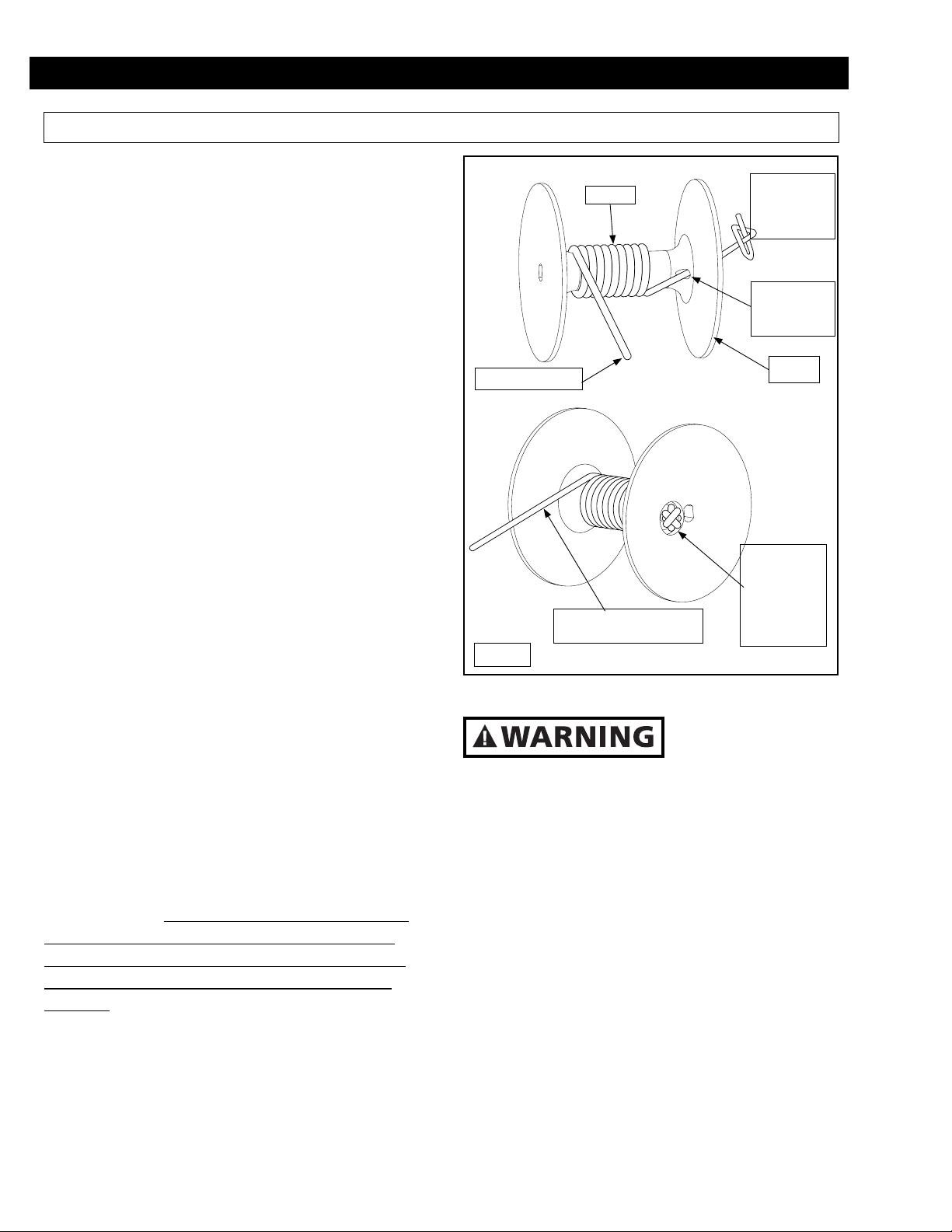
Anchor Line Replacement
Make sure that the windlass is in the free fall
mode of operation. Next, disconnect the power
to the windlass at the battery. Locate the portion
of the rope that inserts through the hole of the
rope spool. Push on this end so that the knotted
portion of rope on the opposite side of the fl ange
is pushed out of the counter bore and is exposed.
Take a thin screwdriver or fl exible piece of
wire and pull the knotted rope end out from between the frame and rope spool fl ange. Untie the
knot or cut the rope just below the knot and pull
the rope out of the spool.
Take the new rope and hold onto the non looped
end and throw the rope out into the water. Follow the illustration in Figure 22 to install the rope
onto the spool. Note: The illustrations in Figure
# depict the rope spool unattached to the windlass for clarity purposes. The rope spool can be
left assembled to the windlass when replacing
the rope. Reconnect the power to the windlass at
the battery. Finally, wind the rope onto the rope
spool while being careful to maintain even wraps
of rope as it winds.
nents.
ROPE
OUT TO ANCHOR
ROPE WINDS ONTO THE
SPOOL OVER THE TOP
Figure 22
Light Bulb Replacement
To prevent damage
to light, do not oper-
ate light for longer than 15 minutes.
1. Remove the two screws that hold the lens
against the winch cover.
2. Remove gasket and inspect for tears or damage, replace if necessary.
3. Rotate the expired light bulb a 1/4 turn or 90
degrees inside the clips and pull out.
4. Replace with new light bulb and reinstall gasket, lens and hardware. The light bulb is a 212-2
automotive bulb.
PULL THE
END OF ROPE
THROUGH AND
TIE END IN
KNOT
INSERT END
OF ROPE INTO
HOLE IN ROPE
SPOOL
ROPE
SPOOL
PULL KNOT
FIRMLY INTO
PLACE IN
THE COUN-
TER BORED
RECESS OF THE
FLANGE
13
Page 14

Operating Instructions and Replacement Parts List Deckmate 25 Freefall Pontoon Windlass
Troubleshooting Guide
Symptom Possible Causes Corrective Action
Windlass does not operate. 1. Disconnected wires, bad circuit
breaker, bad switch.
1. Start by checking the wiring at the battery.
Bypass the circuit breaker and test the winch.
If the winch operates, replace the circuit
breaker.
2. Check wiring insulation for worn or bare
spots that may be causing a short.
3. Check all connections for tightness.
The windlass runs but will
not retrieve rope.
Anchor tends to free fall too
quickly and the rope gets
1. Wave springs on locking gear are
worn.
1. The drag gear spring and washers
are worn.
1. Replace wave springs and push nut.
1. Replace the washers and drag gear spring.
tangled up on the rope spool.
Limited W arranty
A. This Limited W arranty is given by the Pow er winch Di vi sion of the Scott Fetzer Com pa ny (the “Com pa ny”) to the orig i nal purchaser (the
“Purchaser”) of a Pow er winch Prod uct (the “Product”) spec i fied in this man u al. This Limited War ran ty is not trans fer able to any other party.
B. Responsibilities of the Company under this Limited Warranty:
1. Re pair or replace (at the discretion of the Com pa ny) any part or parts of the Prod uct found by the Com pa ny to be defective within a two (2)
year period from the date of pur chase.
2. The Company will pay the transportation charge for ship ment back to the Purchaser of any Prod uct re ceived for legitimate War ran ty re pair.
C. Responsibilities of the Purchaser under this Limited War ran ty:
1. Pur chas er will have to show dated proof of pur chase to qualify for service under the pro vi sions of the Limited Warranty.
2. Promptly notify the Seller or the Com pa ny of any claim hereunder.
3. At the Option of the Company, return the Product to the Company for inspection. Au tho ri za tion must be given pri or to any Prod uct re turn.
Call the Company at 1-800-243-3097 or write the Com pa ny at 2145 West 6th Street, Broomfield, CO 80020 for authorization and com plete
in struc tions on how to return the Prod uct di rect ly to the Com pa ny.
4. Use reasonable care in maintenance, op er a tion, use and storage of the Product in ac cor dance with the in struc tions con tained in the Own er’ s
Man u al.
5. Have Warranty work performed by a deal er or rep re sen ta tive ap proved by the Com pa ny.
6. Except as noted in B.2., transportation charg es are the re spon si bil i ty of the Pur chas er.
D. This Limited W arranty covers:
1. Defects in workmanship or materials.
2. Any part or parts of the Product sold or man u fac tured by the Com pa ny.
E. This Limited W arranty does not cover:
1. Any failure that results from improper in stal la tion of the Product.
2. Any failure that results from accident, Pur chas er’s abuse, neglect, modification, improper main te nance, or fail ure to operate and use the
Product in ac cor dance with the in struc tions pro vid ed in the Own er’s Man u al sup plied with the Prod uct.
F. There is no other express war ran ty. Im plied war ran ties, in clud ing those of mer chant abil i ty and fit ness for a par tic u lar pur pose, are lim ited to one
(1) year from date of pur chase. This is the ex clu sive rem edy and any liability for any and all in ci den tal or con se quen tial dam ag es or ex pens es
what so ev er is ex clud ed.
Some states do not allow lim i ta tions on how long an implied war ran ty lasts, or do not allow ex clu sion or limitation of in ci den tal or con se quen tial
dam ag es, the above lim i ta tions may not apply to you. This Lim it ed Warranty gives you specific legal rights, and you may also have other rights
which vary from state to state.
14
Page 15

Operating Instructions and Replacement Parts List Deckmate 25 Freefall Pontoon Windlass
Technical Information
For information on the operation or repair, please call 1-800-243-3097.
Replacement Parts Information
For information regarding where to order replacement parts, call 1-800-243-3097. Please have the following information available:
Winch Model Number
Winch Serial Number
Part Number and Description
Address correspondence to:
Powerwinch
Attn: Customer Service
2145 West 6th Street
Broomfield, CO 80020
C
A
C
C
C
A A
C
A
A
A
ITEM # PART # DESCRIPTION QTY
A R001429 BOW ROLLER KIT 1
B R001473 COVER KIT 1
C R001474 LIGHT KIT 1
A
A
B
B
B
P44200 DECKMATE 25
PARTS LIST:
WINCH COVER
BOW ROLLER
15
Page 16

DD
FF
FF
EE
EE
EE
GG
GG
HH
II
PP
NN
OO
KK
KK
KK
KK
MM
LL
LL
LL
LL
MM
MM
OO
PP
OO
OO
OO
NN
OO
OO
OO
DD
DD
JJ
JJ
JJ
Operating Instructions and Replacement Parts List Free Fall Pontoon Windlass
P44200 DECKMATE 25
PARTS LIST:
WINCH MECHANISM
SWITCH
ITEM # PART # DESCRIPTION QTY
A R001429 BOW ROLLER KIT 1
B R001473 COVER KIT 1
C R001474 LIGHT KIT 1
D R001475 MOTOR WITH GEAR KIT 1
E R001476 SWITCH KIT 1
F R001477 LIGHT SWITCH KIT 1
G R001478 SWITCH PLATE KIT 1
H P2210700AJ ROPE KIT 1
I R001421 ROPE SPOOL KIT 1
J R001479 SPINOFF GEAR KIT 1
K R001480 LOCKING GEAR KIT 1
L R001481 DRAG GEAR KIT 1
M R001482 SHAFT KIT 1
N R001483 GEAR KIT 1
O R001484 FASTENER KIT 1
P R001485 BEARING KIT 1
NOT
SHOWN
NOT
SHOWN
P1027600AJ CIRCUIT BREAKER 1
P44050 WIRING AND MOUNTING KIT 1
16
 Loading...