

Page 1
Operating Instructions and Replacement Parts List 31’, 36’, 41’, 46’ Class Anchor Winch
Please read and save these instructions. Read carefully before attempting to assemble, install, operate or maintain the product described. Protect yourself
and others by observing all safety information. Failure to comply with instructions could result in personal injury and/or property damage! Retain instructions
for future reference.
Unpacking
When unpacking, inspect carefully for any
damage that may have occurred during
transit. Make sure any loose fittings, bolts,
etc., are tightened before putting unit into
service.
General Safety Information
Danger means a
hazard that will
cause death or serious injury if the
warning is ignored.
Warning means a
hazard that could
cause death or serious injury if the
warning is ignored.
Caution means a
hazard that may
cause minor or moderate injury if the
warning is ignored. It also may mean a
hazard that will only cause damage to
property.
NOTE: Note means any additional
information pertaining to the product or its
proper usage.
The following safety precautions must be
followed at all times:
1. Read all manuals included
with this product carefully.
Be thoroughly familiar with
the controls and the proper
use of the equipment.
Only persons well acquainted with
these rules of safe operation should be
allowed to use the winch.
Never stand
between load or
anchor point and product. If rope breaks,
it could snap with enough force to cause
serious injury or death.
Do not use electrical wire
sizes or types other than
those specified or included
with this product.
®
Free Fall Rope and
Chain Anchor Winch
Always tie off the
mount while cruising to prevent anchor
from breaking free.
2. This product is intended to lift
anchors. Never use product to lift or
move people or animals.
3. Do not wear loose fitting clothing,
scarves, or neck ties during operations
of the product. Loose clothing may
become caught in moving parts and
result in serious personal injury or
death.
Use supplied or recommended
circuit breakers for safe
installation. The warranty will
be void and fire could result
from using improper circuit breakers.
4. Make sure area around anchor point
is clear of people or objects before
releasing or retrieving anchor.
When product
must be tied off onto a cleat to relieve motor
tension and prevent boat damage. When
trailering boat, anchor must be tied off.
5. Never substitute cable for rope.
Always disconnect
battery before attempting to install, service
or relocate unit.
6. Use of a davit with an open loop is not
recommended with this product. Use
a davit with a closed loop to prevent
serious personal injury and/or property
damage.
Never place any
while retrieving or free-falling anchor.
Serious injury could result.
Use only spliced
rodes. Shackles should not be used
to secure rope to chain. Shackles will
damage winch and could cause personal
injury. Use of shackles will also void
warranty.
anchor to a secure
is not in use, anchor
wiring harness from
object in gypsy
rope and chain
7. Stand away from product when in use
and keep children away from product
area at all times.
8. When replacing rope and chain,
always use Powerwinch® brand or
Powerwinch® certified rope and chain.
Do not attempt to
pull a load greater
than rated load of product. Personal injury
and/or property damage could occur.
9. Do not operate product under the
influence of alcohol and/or drugs.
10. Inspect entire rope for weak or worn
condition or kinking (short tight twist
or curl) before use. Replace worn or
kinked rope for proper performance
from product.
11. Inspect the entire chain for broken or
bent links before use. Chain with bent
or broken links should be replaced to
obtain proper performance.
Installation
31’, 36’, 41’ Class
Anchor Winch
This product
requires the use of a
closed loop davit or bow roller. Davit or bow
roller must be installed prior to installing
anchor winch to ensure proper performance.
To install anchor winch, refer to Figure 1
and the following instructions:
TOOLS REQUIRED (NOT INCLUDED):
1. Electric drill
1
/
2. 2
2” hole saw
3. 11/32” drill bit
4. 5/8” drill bit
5. Adjustable wrenches
6. Terminal crimping tool and
wire cutter
7. Center punch
8. Hammer
9. Voltmeter
P1039005AVr1 April, 2012
Page 2
Operating Instructions and Replacement Parts List
Installation (Cont’d)
MATERIAL REQUIRED (INCLUDED WITH
ANCHOR WINCH):
1. Three 5/16”-18 stainless steel threaded
rods. These rods secure anchor
winch to boat. Length is determined by
thickness of boat deck.
2. Three lock washers (5/16” stainless
steel)
3. Three plain washers (5/16” stainless
steel)
4. Three nuts (5/16”-18 stainless steel)
MATERIAL REQUIRED (NOT INCLUDED):
NOTE: A wiring kit from Powerwinch® (Part
No. P55800) is available which contains
items 2-13.
1. Marine plywood for under deck support
(optional)
2. Six 1/4”- 20 x 1/2” hex head stainless
steel screws
3. Six 1/4”- 20 x 1/2” stainless steel nuts
4. Ten 5/16” 8-gauge ring terminals
5. #12 AWG red wire class 105°C
6. #12 AWG black wire class 105°C
7. Four 5/16” 12-gauge ring terminals
8. #8 AWG black wire class 105°C
(6-gauge 40’)
9. #8 AWG red wire class 105°C (6-Gauge
40’)
10. 1” diameter heat shrink tubing
11. 2” diameter heat shrink tubing
12. Wire ties
13. Four 12-gauge insulated female
5/8” Hole in Deck for
Motor Lead Wires
Flat Washer
Hex Nut
Figure 1 - AW31’, 36’, 41’ Class
disconnects
14. Silicone sealer
15. Loctite® 242 thread locker (optional)
MOUNTING ANCHOR WINCH ONTO
DECK
1. Place mounting template in desired
position on deck and secure with tape
into position. Ensure center-line of
gypsy lines up with centerline of davit
or bow roller.
IMPORTANT: Be certain anchor winch is
positioned above rope locker before drilling
any mounting holes. The anchor line and
chain will feed into rope locker through a
1
/
2” hole in boat deck and a molded part
2
called the rode glide. Minimum rope locker
dimensions required for proper storage of
anchor lines are shown in Chart 1.
2. Using a punch, mark center of each
Line Locker
Dimensions Dimensions (L x W)
1/2” x 200’ 15” x 17”
1/2” x 300’ 15” x 24”
5/8” x 200’ 15” x 24”
5/8” x 300’ 16” x 32”
Chart 1
mounting hole to be drilled. Remove
template and drill holes with an electric
drill. There are three
mounting studs, one 2
11/32” holes for
1
/2” hole for deck
insert, and one 5/8” hole for wiring
harness.
3. Place round side of insert into 21/2”
hole and seat deck insert so lip is flush
with boat deck. The half circle portion
Rode Glide
Stud
Lock Washer
NOTE: Mounting and gasket hardware
available in kits (P/N P10349 & P11162).
See page 11 for ordering information
of deck insert must be pointing toward
bow of boat.
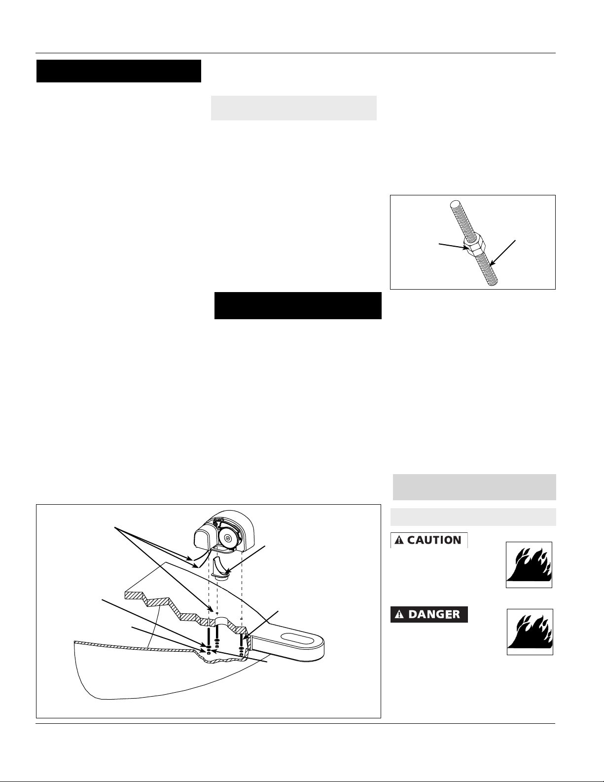
4. Insert three mounting studs into
threaded holes on underside of winch.
A small amount of thread locker can be
used to secure studs in housing. Use
two mounting nuts to help tighten studs
into housing as shown in Figure 2.
5. Gently guide winch over rode glide so
loop on anchor winch housing slides
over deck insert. Slide three mount-ing
studs into the three mounting holes
Mounting StudMounting
Nuts
Figure 2
in deck. Feed wiring harness from
underside of winch through 5/8” hole.
6. The winch must fit squarely over deck
insert and onto deck. Slide flat washers
and lock washers onto mounting studs.
Tighten nuts to fully secure the winch to
the deck.
7. Examine winch to make sure unit is
securely fastened and that centerline of
gypsy is aligned with centerline of bow
roller or davit.
Wiring Installation
WIRING AND SWITCH INSTALLATION
Do not use electrical wire
sizes or types other than those
specified or included with this
product.
Use supplied or recommended
circuit breakers for safe
installation. The warranty will be
void and fire can result from using improper
circuit breakers.
2
Page 3
31’, 36’, 41’, 46’ Class Anchor Winch
Installation (Cont’d)
and attach plate using four #8 round
head wood screws.
4. Measure and cut 8-gauge red and
Always disconnect
wiring harness from
battery before attempting to install, service or
relocate unit.
Follow order of
wiring steps to ensure
power is not applied to anchor winch until all
wires and circuit breakers are installed.
black wire to run from anchor winch to
switch. Allow some slack to prevent
connections from being too short and
so connections can be crimped to
end of wire. Install wire in boat before
crimping any connections. Cable ties
can be used to secure wiring to boat.
5. When running wire from anchor winch
Always keep wires away
from intense sources
of heat. Be sure newly
installed wires are away from any exposed
bare wires.
to switch, be sure to keep wire away
from sources of intense heat or areas
where the insulation of wire could be
worn away.
6. After wire is installed and secured,
connection to anchor winch can be
made.
SWITCH INSTALLATION
Make sure all crimps/
connections can withstand
at least 25 pounds of pullout
force. Failure to make strong enough crimps
between wire connectors and wires could
create a fire hazard.
1. Select a suitable location (console,
etc.) to locate switch. Make sure
there is enough room behind switch
mounting surface for entire switch and
wires.
2. Cut a hole 1
3/4” high and 1” wide.
3. Apply a thin bead of silicone sealer
around edge of switch mounting plate
Anchor
Winch
*NOTE: 41’ Class uses
6-gauge red & black wire
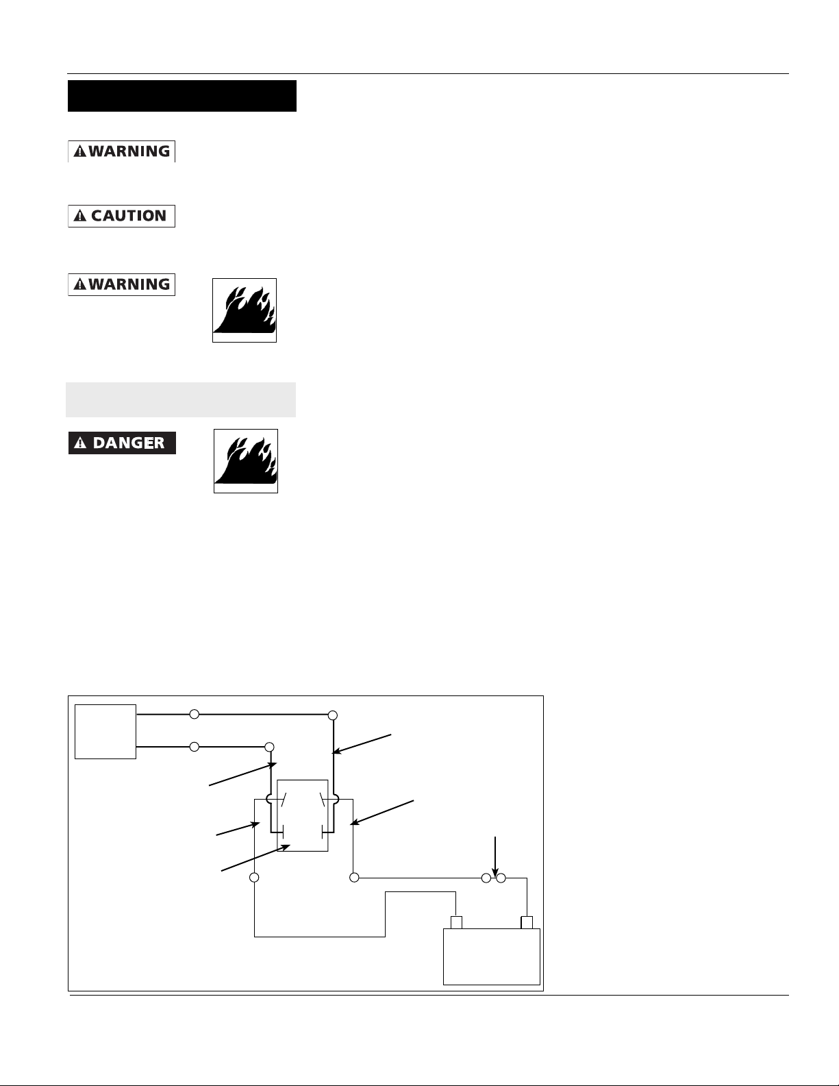
Figure 3 - Wiring Diagram for 31’, 36’, 41’ Anchor Winch
Black
Wire
Green
Wire
12-Gauge
Red Wire
12-Gauge
Black Wire
Control Switch
(Back View)
*8-Gauge Black Wire
*8-Gauge
Red Wire
*8-Gauge Black Wire
7. Crimp a 5/16” ring terminal to 8-gauge
red wire just cut.
8. Using a 1/4”-20 x 1/2” screw, connect
8-gauge red wire to ring terminal on
the green wire coming from anchor
winch. Tighten a
1/4”-20 nut to secure ring terminals
together. Protect junction by placing a
1” diameter piece of heat shrink tubing
over connection and applying heat
until tubing is secure.
9. Crimp a 5/16” ring terminal to 8-gauge
black wire just cut.
10. Using a 1/4”-20 x 1/2” screw, connect
8-gauge black wire to ring terminal on
black wire coming from anchor winch.
Tighten a 1/4”-20 nut to secure ring
D
C
A
B
12-Gauge
Black Wire
12-Gauge
Red Wire
*8-Gauge Red Wire
-
Circuit
Breaker
Battery
terminals together. Protect junction
by placing a 1” diameter piece of
heat shrink tubing over connection
and applying heat until the tubing is
secure.
SWITCH TO ANCHOR WINCH
The switch needs 12-gauge wire
connections and wiring just run is 8gauge. To complete anchor winch
to switch connections construct two
conversion wires by following these steps:
1. This switch wire is for the positive
(red) lead.
2. Cut a 1 foot section of 12-gauge red
wire and crimp a 5/16” ring terminal to
one end.
3. Crimp an insulated female disconnect
to other end.
4. Crimp a 5/16” ring terminal to 8gauge red wire coming from anchor
winch.
5. Using a 1/4”-20 x 1/2” screw, connect
8-gauge red wire coming from anchor
winch to ring terminal on red switch
wire. Tighten a 1/4”-20 nut to secure
ring terminals together. Protect
junction by placing a 1” diameter piece
of heat shrink tubing over connection
and applying heat until tubing is
secure.
6. Plug insulated female disconnect on
end of red switch wire to rocker switch
on terminal marked “A”.
7. To construct second switch wire and
make connection to switch, cut a 1
foot section of 12-gauge black wire
and crimp a 5/16” ring terminal to one
end.
8. Crimp an insulated female disconnect
to other end.
9. Crimp a 5/16” ring terminal to 8- gauge
black wire coming from anchor winch.
10. Using a 1/4”-20 x 1/2” screw, connect
8-gauge black wire coming from anchor
winch to ring terminal on black switch
wire. Tighten a 1/4”-20 nut to secure
ring terminals together. Protect junction
by placing a 1” diameter piece of heat
shrink tubing over connection and
applying heat until tubing is secure.
+
11. Plug insulated female disconnect on end
of black switch wire to rocker switch on
terminal marked “B”.
3
Page 4

Operating Instructions and Replacement Parts List
Installation (Cont’d)
SWITCH TO BATTERY
Make sure all crimps/
connections can withstand
at least 25 pounds of pullout
force. Failure to make strong enough crimps
between wire connectors and wires could
create a fire hazard.
1. Measure and cut 8-gauge red and black
wire to run from switch to battery. Allow
some slack to prevent connections
being too short leaving enough room to
crimp end of wire. Install wire in boat
before crimping any connections. Use
cable ties to secure wiring to boat.
2. When running wire from switch to
battery, be sure to keep wire away from
sources of intense heat or areas where
insulation of wire could be worn away.
3. After wire is installed and secured, make
remaining switch connections .
4. Make two more conversion wires
t
o attach battery wiring to switch by
following these steps:
a. This switch wire is for the positive
(red) lead to battery.
b. Cut a 1 foot section of 12-gauge red
wire and crimp a 5/16” ring terminal
to one end.
c. Crimp an insulated female
disconnect to other end.
d. Crimp a 5/16” ring terminal to 8-
gauge red wire coming from battery.
e. Using a 1/4”-20 x 1/2” screw,
connect 8-gauge red wire coming
from battery to ring terminal on red
switch wire. Tighten a 1/4”-20 nut
to secure ring terminals together.
Protect junction by placing a 1”
diameter piece of heat shrink tubing
over connection and applying heat
until tubing is secure.
f. Plug insulated female disconnect
on end of red switch wire to rocker
switch on terminal marked “D”.
g. To c
onstruct second switch wire and
make connection to switch, cut a 1
foot section of 12-gauge black wire
and crimp a 5/16” ring terminal to
one end.
h. Crimp an insulated female
disconnect to other end.
i. Crimp a 5/16” ring terminal to
8- gauge black wire coming from
battery.
j. Using a 1/4”-20 x 1/2” screw,
connect 8-gauge black wire coming
from battery to ring terminal on
black switch wire. Tighten a 1/4”20 nut to secure ring terminals
together. Protect junction by
placing a 1” diameter piece of heat
shrink tubing over connection and
applying heat until tubing is secure.
k. Plug insulated female disconnect on
end of black switch wire to r
ocker
switch on terminal marked “C”.
BATTERY CONNECTIONS
1. Crimp a 5/16” ring terminal to end of
8-gauge red and black wire coming
from switch.
2. Create a jumper to connect circuit
breaker to battery by cutting a 1
foot piece of 8-gauge red wire and
crimping a 5/16” ring terminal to each
end.
3. Assemble circuit breaker to jumper by
placing ring terminal onto post marked
“bat” and secure with nut on circuit
breaker
4. Assemble circuit breaker to switch by
attaching remaining 8-gauge wire to
post on circuit breaker marked “aux.”
5. Protect connection by placing a piece
of 2” diameter heat shrink tubing over
connection and applying heat until
tubing i
s secure.
6. Connect 8-gauge black wire from
switch to negative (-) battery terminal.
7. Connect 8-gauge black wire from
switch to negative (+) battery terminal.
8. Snap control switch into switch plate
and proceed to unit test instructions.
UNIT TEST
1. With no rope or chain in gypsy, press
switch in upward position. If wiring to
switch terminals is correct, gypsy will
spin counterclockwise.
2. If gypsy does not turn, but motor runs,
switch is incorrectly wired.
3. To correct, exchange wires at terminals
A and B on switch.
46’ Class Anchor Winch
This product
closed loop davit or bow roller. The davit
or bow roller must be installed on boat
prior to installing product to ensure proper
performance.
To install anchor winch, refer to Figure 4
and the following instructions:
TOOLS REQUIRED (NOT INCLUDED):
1. Electric drill
1
/2” hole saw
2. 2
11/32” drill bit
3.
4. 5/8” drill bit
5. Adjustable wrenches
6. Terminal crimping tool and
wire cutter
7. Center punch
8. Hammer
9. Voltmeter
MATERIAL REQUIRED (INCLUDED
WITH ANCHOR WINCH):
1. Three 5/16”-18 stainless steel
threaded rods. These rods secure
anchor winch to boat. Length is
determined by thickness of boat deck.
2. Three lock washers (5/16” stainless
steel)
3. Three plain washers (5/16” stainless
steel)
4. Three nuts (5/16”-18 stainless steel)
MATERIAL REQUIRED (NOT
INCLUDED):
NOTE: A wiring kit from Powerwinch®
(Part No. P10284) is available which
contains items 2-15.
1. Marine plywood for under deck
support (optional)
Six 3/8” 6-gauge ring terminals
2.
3. #6 AWG red wire class 105°C
8. #6 AWG black wire class 105°C
4. Two 5/16” 16-gauge ring terminals
5. #16 AWG black wire class 105°C
6. #16 AWG white wire class 105°C
7. #16 AWG red wire class 105°C
8. Six 16-gauge insulated female
disconnects
9. Two 1/4”-20 x 1/2” stainless steel hex
head screw
requires use of
a
4
Page 5

31’, 36’, 41’, 46’ Class Anchor Winch
Installation (Cont’d)
10. Two 1/4”-20 x 1/2” stainless steel nuts
11. 1” diameter heat shrink tubing
12. 2” diameter heat shrink tubing
13. ATO inline fuse holder
14. 10A ATO style fuse
15. Wire ties
16. Loctite® 242 thread locker (optional)
17. Silicone sealer
18. four 3/8” 6-gauge female disconnects
LOCATING MOUNTING HOLES FOR
ANCHOR WINCH
1. Place mounting template in desired
position on deck and secure with tape
into position. Ensure center-line of
gypsy lines up with centerline of davit
or bow roller.
IMPORTANT: Be certain anchor winch
is positioned above rope locker before
drilling any mounting holes. The anchor
line and chain will feed into rope locker
through a 2
molded part called deck insert. Minimum
rope locker dimensions required for
proper storage of anchor lines are shown
in Chart 2.
2. Spot holes with center punch as
shown on template. Use an electric
drill to drill holes. There are three
32
2” hole for deck insert, and one 5/8”
hole for wiring harness.
3. Place round side of insert into 2
and seat deck insert so lip is flush with
Figure 4 - AW46’ Class
1
/
2” hole in boat deck and a
11/
” holes for mounting studs, one 21/
1
/2” hole
5/8” Hole in Deck for
Motor Lead Wires
Hex Nut
Line Locker
Dimensions Dimensions (L x W)
1/2” x 200’ 15” x 17”
1/2” x 300’ 15” x 24”
5/8” x 200’ 15” x 24”
5/8” x 300’ 16” x 32”
Chart 2
boat deck. The half circle portion of
deck insert must be pointing toward
bow of boat.
4. Insert three mounting studs into
threaded holes on underside of winch.
A small amount of thread locker can
be used to secure studs in housing.
Use two mounting nuts to help tighten
studs into housing as shown in Figure
5.
5. Gently guide winch over rode glide
Mounting StudMounting
Nuts
Figure 5
so loop on anchor winch housing
slides over deck insert. Slide three
mounting studs into three mounting
holes in deck. Feed wiring harness
from underside of winch through 5/8”
hole.
6. The winch must fit squarely over
deck insert and onto deck. Slide
flat washers and lock washers onto
Rode Glide
Stud
Flat Washer
Lock Washer
NOTE: Mounting and gasket hardware
available in kits (P/N P10349 & P11162)
mounting studs. Tighten nuts to fully
secure winch to deck.
8. Examine winch to make sure unit is
securely fastened and that center-line
of gypsy is aligned with centerline of
bow roller or davit.
WIRING AND SWITCH INSTALLATION
Do not use electrical wire
sizes or types other than
those specified or included
with this product.
Use supplied or recommended
circuit breakers for safe
installation. The warranty will
be void and fire could result
from using improper circuit
breakers.
Always disconnect
battery before attempting to install, service
or relocate unit.
Follow order of
ensure power is not applied to anchor
winch until all wires and circuit breakers
are installed.
Always keep wires away
from intense sources of heat.
Be sure newly installed wires
are away from any exposed bare wires.
wiring harness from
wiring steps to
SWITCH AND SOLENOID LOCATION
1. Select a suitable location (console,
etc.) to locate switch. Make sure
there is enough room behind switch
mounting surface for entire switch
and wires.
3
2. Cut a hole 1
/
4” high and 1” wide.
3. Apply a thin band of silicone sealer
around edge of switch mounting plate
and attach plate using four #8 round
head wood screws.
4. Select a suitable location for relay
(reversing switch). Locate reversing
switch within 6-8 feet of switch plate
and in a location away from exposure
to water. Mount relay with power
terminals facing up.
5
Page 6

Operating Instructions and Replacement Parts List
Installation (Cont’d)
WIRING ANCHOR WINCH TO
RELAY (REFER TO FIGURE 6)
Make sure all crimps/
connections can withstand
at least 25 pounds of pullout
force. Failure to make strong
enough crimps between wire
connectors and wires could
create a fire hazard.
1. Measure and cut 6-gauge red and
black wire to run from anchor winch to
relay. Allow some slack to prevent
connections being too short leaving
enough room to crimp end of wire.
Install wire in boat before crimping any
connections. Use cable ties to secure
wiring to boat.
2. When running wire from anchor winch
to relay, be sure to keep wire away
Red
t or areas
Black 6-Gauge
Red 6-Gauge
from sources of intense hea
where insulation of wire could be worn
away. Cable ties can be used to secure
wiring to boat.
3. After wire is installed and secured,
connection to anchor winch can be
made.
4. Crimp 3/8” ring terminals to 6-gauge
red and black wire connected to anchor
winch.
5.
Attach 6-gauge red wire to red wire
coming from anchor winch. Secure
junction by placing a 1/4”-20 x 1/2”
Black
Anchor
(from motor)
Winch
(from motor)
screw through ring terminals and tighten
a 1/4”-20 nut on screw. Protect junction
by placing a 1” diameter piece of heat
shrink tubing over connection and
applying heat until tubing is secure.
6. Attach 6-gauge black wire to black wire
coming from anchor winch. The junction
can be secured in same manner as 6gauge red wire in step 5.
7. The connections at relay from
anchor winch can now be made.
8. Crimp 3
/8” female disconnects to red and
black wires to be attached to relay.
9. Connect 6-gauge red wire to relay
on post marked M1 and secure
by tightening supplied nut.
10. Connect 6-gauge black wire to relay
on post marked M2 and secure
by tightening supplied nut.
WIRING SWITCH TO RELAY
Make sure all crimps/
connections can withstand
at least 25 pounds of pullout
force. Failure to make strong
enough crimps between wire
connectors and wires could
create a fire hazard.
1. Measure a 16-gauge red, white,
and black wire to run from switch to
relay. Allow some slack to prevent
connections being too short leaving
enough room to crimp end of wire.
Install wire in boat before crimping any
nnections. Use cable ties to secure
co
wiring to boat.
2. When running wire from switch to
relay, be sure to keep wire away
from sources of intense heat or areas
where insulation of wire could be worn
away. Cable tie
s can be used to secure
wiring to boat.
3. Once wires are run and secured,
connect wires from switch to relay.
4. Starting on the wire ends for switch,
crimp one 16-gauge insulated female
disconnect to red wire.
5. Plug red wire into middle post on back
of switch.
6. Next, crimp a 16-gauge insulated
female disconnect to white wire.
7. Plug white wire into top post on back of
switch.
8. Crimp a 16-gauge insulated female
disconnect to black wire.
9. Plug black wire into bottom post on
back of switch.
10. Make connections at relay.
11. Crimp a 16-gauge insulated female
disconnect to white wire.
12. Plug wh
e into terminal marked S1
ite wir
on the relay.
13. Crimp a 16-gauge insulated female
disconnect to black wire.
14. Plug black wire into terminal marked S2
on relay.
15. Using a 16-gauge butt connector,
connect fuse holder to red wire.
16. Crimp a 16-gauge insulated female disconnect
to remaining open end of fuse holder.
17. Attach fuse holder with disconnect
crimped to it to terminal marked S3
on relay.
18. Insert 10 amp ATO style fuse in fu
se
holder.
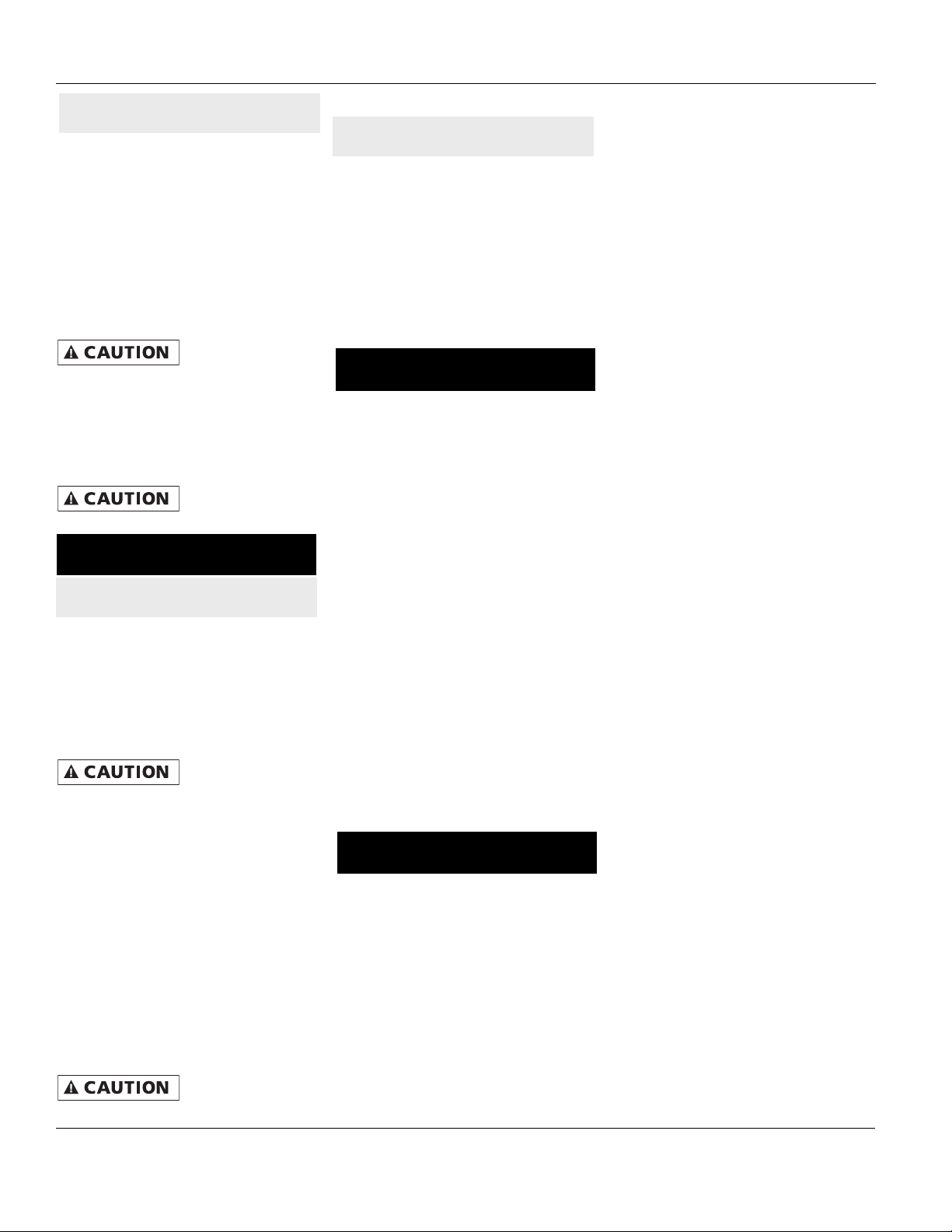
UP
DWN
Control
Switch
White 16-Gauge
Red 16-Gauge
Black 16-Gauge
10A Inline Fuse
M1 M2
S1
S3
S2
Relay
Module
Red 6-Gauge
Black 6-Gauge
6
Circuit Breaker
Battery
PW46001
WIRING RELAY TO BATTERY
Make sure all
connections can
at least 25 pounds of pullout
force. Failure to make strong
enough crimps between wire
connectors and wires could create a fire
hazard.
crimps/
withstand
1. Measure 6-gauge red and black wire
to run from relay to battery. Allow
Page 7

31’, 36’, 41’, 46’ Class Anchor Winch
Installation (Cont’d)
some slack to prevent connections
being too short leaving enough room to
crimp end of wire. Install wire in boat
before crimping any connections. Use
cable ties to secure wiring to boat.
2. When running wire from solenoid to
battery, keep wire away from sources of
intense heat or areas where insulation
of wire could be worn away.
3. Once wires are run and secured,
connect wires from switch to solenoid.
4. Crimp 3/8” ring terminals to 6-gauge
red and black wire to be connected to
solenoid.
5. Attach 6-gauge red wire to post marked
“+” on solenoid. Secure with supplied
nut.
6. Attach 6-gauge black wire to post
marked “-” on solenoid. Secure with
supplied nut.
7. Attach end of the jumper with ring
terminal to terminal marked “-” on
solenoid.
8. At end of 6-gauge red wire coming from
solenoid, crimp a 3/8” ring terminal.
9. At end of 6-gauge black wire coming
from solenoid, crimp a 3/8” ring terminal.
10. Create a jumper to connect circuit
breaker to battery by cutting a 5/16” ring
terminal to each end.
11. Attach circuit breaker to jumper just
created by securing post marked “bat”
through one of the ring terminals.
Secure with nut on circuit breaker post.
12. Attach remaining 6-gauge red wire
coming from the solenoid on circuit
breaker to post . The post on circuit
breaker marked “aux” must be
connected to this wire.
13. Protect connection by placing a piece
of 2” diameter heat shrink tube over
connection and applying heat until
tubing is secure.
14. The 6-gauge black wire from solenoid
can now be connected to negative (-)
battery terminal.
15. The 6-gauge red wire with circuit
breaker can now be connected to
positive (+) battery terminal.
16. The connections are now complete.
17. Snap control switch into switch plate and
proceed with unit test instructions.
UNIT TEST
1. Without rope or chain in gypsy, press
and hold switch in upward position. If
wiring to switch terminals is correct,
gypsy will spin counterclockwise.
2. If gypsy does not turn, but motor runs,
switch is incorrectly wired.
3. To correct, exchange locations of black
and white wires on back of switch.
4. If motor does not run, check to make
sure fuse has been installed in fuse
holder located in 16-gauge red switch
wire.
Anchoring Instructions
LOADING ROPE AND CHAIN
Use of rope NOT
specified by
Powerwinch® could cause unit or property
damage or personal injury and will void
warranty.
1. Feed rope through davit or bow roller
and pull toward anchor winch. Make
sure rope is not twisted or kinked and
can freely run through bow roller or
davit.
2. Lift finger and insert rope into rode
glide and down into rope locker. Allow
enough slack so rope can be tied off in
rope locker.
3. Release finger and make sure rope is
firmly seated in the gypsy.
4. Go below to rope locker and tie rope off.
5. Press switch up and begin retrieving
rope and chain into rope locker.
USING PROPER ROPE AND CHAIN
Powerwinch® Recommended Rope and Chain
Product Model Required Rope Required Chain
31’/36’ Class
41’/46’ Class
FAILURE TO USE RECOMMENDED ROPE AND CHAIN WILL VOID PRODUCT
WARRANTY
Chart 3 - Recommended Rope and Chain
1/2” diameter, three strand,
medium lay, premium nylon
Powerwinch® rope or New
England Rope
5/8” diameter, three strand
medium lay, premium nylon
Powerwinch® rope or New
England Rope
1/4” Acco G4 Hi-Test chain.
Failure to use recommended
chain will invalidate the
warranty of the product
5/16” Acco G4 Hi-Test chain.
Failure to use recommended
chain will invalidate the
warranty of the product
7
This product is a uniquely designed device
to raise and lower anchors using spliced
rope and chain rodes (a rode is a length of
rope and chain). It is very important that
only sizes and brands of spliced rope and
chain rodes specified by Powerwinch® are
used in this product. Use of non-specified
ropes and chains could cause reduced
levels of performance or serious personal
injury and/or property damage. Use of
non-specified ropes and chains will also
invalidate the product warranty. The ropes
and chain rodes specified for this anchor
winch are shown on page 7 in Chart 3.
Once an anchoring spot and depth is
determined, anchor may be released.
Page 8
Operating Instructions and Replacement Parts List
ANCHORING
• Turn boat into wind and place
motor(s) in neutral.
• After boat has stopped all forward
progress, drop anchor by pressing
anchor winch switch to down position
for five seconds.
• The anchor will release from bow
roller or davit and free-fall to sea bed.
Once anchor has begun free-falling,
it is safe to release switch.
After desired
amount of scope has
been released from anchor winch, retrieve
3-5 feet of line with anchor winch by pressing
switch to up position.
• Place boat’s motor(s) in neutral and
allow boat to drift back and set anchor
in sea bed.
Tie off anchor line
to a deck cleat. Do
NOT use anchor winch to tie off anchor.
Unit Operation
RETRIEVING THE ANCHOR
• Untie anchor line from deck cleat.
• To retrieve anchor, align bow of boat
with anchor rode.
• Place motor(s) in forward and move
boat slowly toward anchor point.
While moving, press anchor winch
switch up and retrieve anchor rode.
Do NOT pull boat
to anchor point
solely with anchor winch. The anchor
winch’s gear train or motor could suffer
damage. The boat’s motor MUST be used
to move boat toward anchor point.
• When chain begins entering gypsy,
this is an indication that the rode is
almost retrieved. Take care to prevent
anchor from being pulled up too
quickly into davit or bow roller.
• When anchor enters davit or bow
roller, do not place too much tension
on chain between anchor winch and
anchor. This could cause damage to
gypsy or davit. It may also degrade
free-fall performance on next anchor
drop.
Never use anchor
winch to break
anchor free. Never reverse anchor winch
while unit is in free-fall.
ANCHOR RELEASE (FREE-FALL)
To release anchor, push switch to down
position and hold for 5 seconds. The unit
will disengage and anchor will fall freely.
When sufficient line has been released and
gypsy has stopped turning, push switch to
up position and pull in slack on rode.
To retrieve anchor, push switch to up
position. When anchor is in bow roller or
davit, release switch. Make sure anchor is
secured in davit or bow roller.
Maintenance
1. Following each boat outing, flush
exterior of winch with fresh water. Use
only mild detergents to clean exterior.
Use of solvents may cause damage
and reduce effectiveness of corrosion
resistant parts, paint and gaskets, as
well as void product warranty.
2. Every 6 months inspect gypsy, stripper,
finger and deck insert for wear. Replace
any worn components.
3. Check electrical connections every 6
months for corrosion. Replace any
connection or wire which is damaged,
corroded, frayed or worn.
4. Check rope periodically for abrasion or
deep cuts. Never splice an old rope
with a new rope. If replacement is
necessary, use only Powerwinch® rope
specifically designed for this product.
5. Check chain periodically for bent links
and corrosion. Damaged links can
become jammed in gypsy or damage
stripper and finger. Use of damaged
chain will void warranty.
Technical Service
For information regarding operation or
repair of this product, please call 800-2433097 for assistance.
8
Page 9

31’, 36’, 41’, 46’ Class Anchor Winch
Troubleshooting Guide
Symptom Possible Cause(s) Corrective Action
Product will not operate
Rope slips or jams when
retrieving
Chain slips or jams when
retrieving or free falling
Anchor line will not freefall
1. Disconnected, bad wiring or bad
circuit breakers
2. 10A fuse not in fuse holder or
burned out (AW46’ only)
1. Wrong rope size
2. Rope is frayed and worn
3. Rope is too stiff
1. Wrong chain size
2. Chain links are bent or corroded
3. Chain is kinked
1. Rope tangled in rope locker
2. Chain is kinked
3. Anchor is wedged in bow roller
1. Check each connection with a voltmeter and with switch
engaged. Check circuit breaker connection closely
2. Replace fuse
1. Replace rope with Powerwinch® certified 1/2“ or 5/8“ rope
2. Replace rope
3. Replace rope
1. Replace chain with Powerwinch® certified 1/4“ or 5/16“
Acco G4 High Test chain
2. Replace chain
3. Unkink chain
1. Be sure rope is not kinked or twisted before anchoring
2. Unkink chain
3. Free anchor
LIMITED WARRANTY
A.This Limited Warranty is given by the Powerwinch Division of the Scott Fetzer Company (the “Company”) to the original purchaser (the
“Purchaser”) of a Powerwinch Product (the “Product”) specified in this manual. This Limited Warranty is not transferable to any other
party.
B. Responsibilities of the Company under this Limited Warranty:
1. Repair or replace (at the discretion of the Company) any part or parts of the Product found by the Company to be defective within a
2 year (AW31’), 3 year (36’/41’/46’) period from the date of purchase.
2. The Company will pay the transportation charge for shipment back to the Purchaser of any Product received for legitimate Warranty
repair.
C. Responsibilities of the Purchaser under this Limited Warranty:
1. Complete (fully and accurately) and return to the Company, the Warranty card included in the box. Otherwise, Purchaser will have
to show dated proof of purchase to qualify for service under the provisions of the Limited Warranty.
2. Promptly notify the Seller or the Company of any claim hereunder.
3. Use reasonable care in maintenance, operation, use and storage of the Product in accordance with the instructions contained in the
Owner’s Manual.
4. Have Warranty work performed by an authorized Powerwinch warranty repair center or representative approved by the Company.
5. Except as noted in B.2., transportation charges are the responsibility of the Purchaser.
D. This Limited Warranty covers:
1. Defects in workmanship or materials.
2. Any part or parts of the Product sold or manufactured by the Company.
E. This Limited Warranty does not cover:
1. Any failure that results from improper installation of the Product.
2. Any failure that results from accident, Purchaser’s abuse, neglect, modification, improper maintenance, or failure to operate and
use the Product in accordance with the instructions provided in the Owner’s Manual supplied with the Product.
F. There is no other express warranty. Implied warranties, including those of merchantability and fitness for a particular purpose, are
limited to one (1) year from date of purchase. This is the exclusive remedy and any liability for any and all incidental or consequential
damages or expenses whatsoever is excluded. Some states do not allow limitations on how long an implied warranty lasts, or do not
allow exclusion or limitation of incidental or consequential damages, the above limitations may not apply to you.
Do Not Return Your Product To The Factory. Unauthorized Returns Will Delay Repair of Your Product and Incurr Additional
Shipping Charges to You.
This Limited Warranty gives you specific legal rights, and you may also have other rights which vary from state to state.
Powerwinch reserves the right to alter specifications on any product without notice.
All rights reserved. This publication or parts thereof may not be reproduced in any form without written permission.
9
Page 10
Operating Instructions and Replacement Parts List
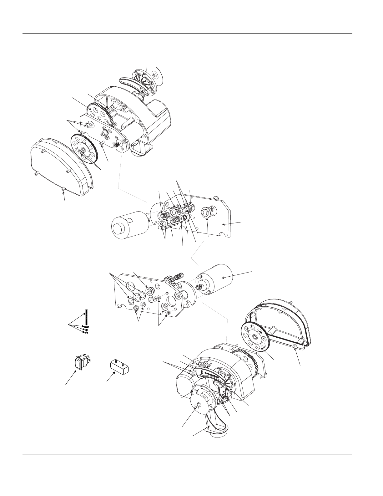
For Replacement Parts, Call 1-800-243-3097
J
I
J
J
J
F, G
F, G
F
F, G
G
J
K
G
H
H
H,J
H,J
F,G,J
J
L
M
D
H,J
E,J
A
A,J
A
B
H,J
D,K
C,J
E
I
J
B
C
B,J
J
Figure 7 - Replacement Parts Illustration for 31’, 36’, 41’ Class Anchor Winch
10
Page 11

31’, 36’, 41’, 46’ Class Anchor Winch
For Replacement Parts, Call 1-800-243-3097
J
I
J
H,J
H
F,G
N
H,J
E
F,G
G
K
D,K
J
J
D
G,J
G
H,J
J
L
Figure 8 - Replacement Parts Illustration for 46’ Class Anchor Winch
M
A,J
A
B
B,J
A
I
J
B
C
C,J
J
11
Page 12

For Replacement Parts, Call 1-800-243-3097
Please provide following information: Address parts correspondence to:
-Model number Carefree/Powerwinch
-Serial number (if any) 2145 West 6th Street
-Part description and number as shown in parts list Broomfield, CO 80020.
Ref. Letter Description 31’ Class 36’ Class 41’ Class
A Replacement Finger Kit R001430 R001443 R001443
B Replacement Gypsy Kit R001431 R001431 R001449
C Replacement Stripper Kit R001432 R001432 R001432
D Replacement Bearing Kit R001433 R001433 R001433
E Replacement Motor Kit R001434 R001434 R001434
46’ Class
R001443
R001449
R001432
R001443
R001450
F Replacement Shock Absorber Kit R001435 R001435 R001435
G Replacement Spinoff Gear/Shaft
R001436 R001436 R001436
R001446
Kit
H Replacement Locking Gear Kit R001437 R001437 R001437
I Replacement Gear Kit R001438 R001438 R001438
J Replacement Fastener Kit R001439 R001439 R001439
K Replacement Motor Plate Kit R001440 R001440 R001440
L Replacement Switch Kit R001441 R001441 R001441
R001445
R001438
R001444
R001440
R001447
M Replacement Circuit Breaker Kit P1027600AJ P1027600AJ P1027600AJ P1064800AJ
N Replacement Relay Kit - - -
P1028200AJ
-
Page 13

Operating Instructions and Replacement Parts List
Notes
31’, 36’, 41’, 46’ Class Anchor Winch
 Loading...