

Page 1
www.tera.co
User Manual
TR-7200
TR-7200
TR-7400
TR-7400
TERA
Thank you for purchasing TERA model TR-7200/TR-7400.
These models feature 1,024 channels, 64 zones. These
radios models are built to D M R standards which insures
operation worldwide.
To get the most out of your radio, please read this manual
carefully before use.
Page 2
Initial Programming
This commercial handheld radio ships from the manufacture “Displayed Locked” per FCC rules. You must
first use the programming software to unlock this radio for the first time of use. You will need the programming
cable to connect your radio to your computer for programming. Please contact your dealer for radio programming
software.
When programming this radio for the first time , it is recommended you first READ the radio with the software
and then save this file for future reference. In addition, after you READ this radio with software, first make
your programming and frequency changes, then send this edited file back to your radio. Please contact
the dealer you purchased this radio from or TERA should you have any questions.
On-line Service and Support
The TERA website provides additional information about
obtaining service or support for the TERA line of digital
portable radio and accessories.
visit: www.tera.co
User Manual
Safety Matters
The following recommendations will help you understand this radios safety requirements.
1. Only qualified TERA technicians are allowed to service this . Do
not disassemble the radio by yourself as it will void the warranty.
2. Use only the TERA brand battery pack and desk charger, so as to not damage the
transceiver.
3. Do not expose this radio to long periods of direct sunlight, or hot or humid areas.
4. Do not put this radio in dusty or dirty locations.
5. Do not use harsh chemicals, cleaning solvents, or strong detergent to wash this radio.
6. Never transmit on this radio without an antenna.
Caution
Safety and operability of this radio can’t be guaranteed unless TERA brand accessories
or parts are used.
digital portable radio
Contents
Safety Matters
Product Inspection
Get Acquainted
Cautions in Charging
Antenna Information
Attaching and Removing
Attaching/Removing the battery
Attaching/Removing the antenna
Installing/Removing the Belt Clip
02
03
04
05
05
06
06
07
08
Installing Hand Strap
Attaching the Audio Accessory /Removing
Radio Overview
Status Indicators
LED Indicator
Programmable Keys
Basic Operations
Turning the Radio On/Off
Adjusting the Volume
08
09
10
12
13
14
15
15
15
Page 3
Selecting a Zone
Contents
Selecting a Channel
Analog/Digital Switch
Locking/Unlocking the Keypad
Private Call
Group Call
Transmitting an All Call
Menu Navigation
Message
Contact
15
15
16
16
16
17
17
18
18
18
Call Logs
Scan
Settings
TOT
TX Power
Basic Settings
Functions and Operations
Care and Maintenance
Service and Support
Terms of Warranty
19
20
20
20
21
21
22
26
27
28
Safety Matters
Please read rules below. Nonobservance of these rules may cause
danger or violation of law.
The use this radio must comply with regulations of local government.
Turn off the radio before you enter places of flammable or
explosive environment.
Do not replace or charge battery pack in places of flammable
or explosive environment.
Turn off the radio before you approach blast area and detonator
area.
Do not use the damaged antenna which may cause lightly burn
on skin.
Only qualified technician are allowed to maintain this two-way
radio. Do not disassemble the radio by yourself.
To avoid problems caused by electro magneti c int erferen ce or
electromagnetic compatibility, please turn off the radio in places
with “Wireless Communication Transmit Equipment Prohibited”
mark, such as hospitals or other health care places. When taking
a plane, turn off the radio if required.
In a car with air bag, do not place the radio within possibly involved
area when air bag expands.
Do not expose the radio to direct sunlight or near heating devices
for a long time.
Keep the radio vertical and speak near the mi croph on e duri ng
transmitting.
Make sure that the antenna is 2.5 cm away from the body during
transmitting if you carry the radio on your body.
Safety Matters
01
Product Inspection
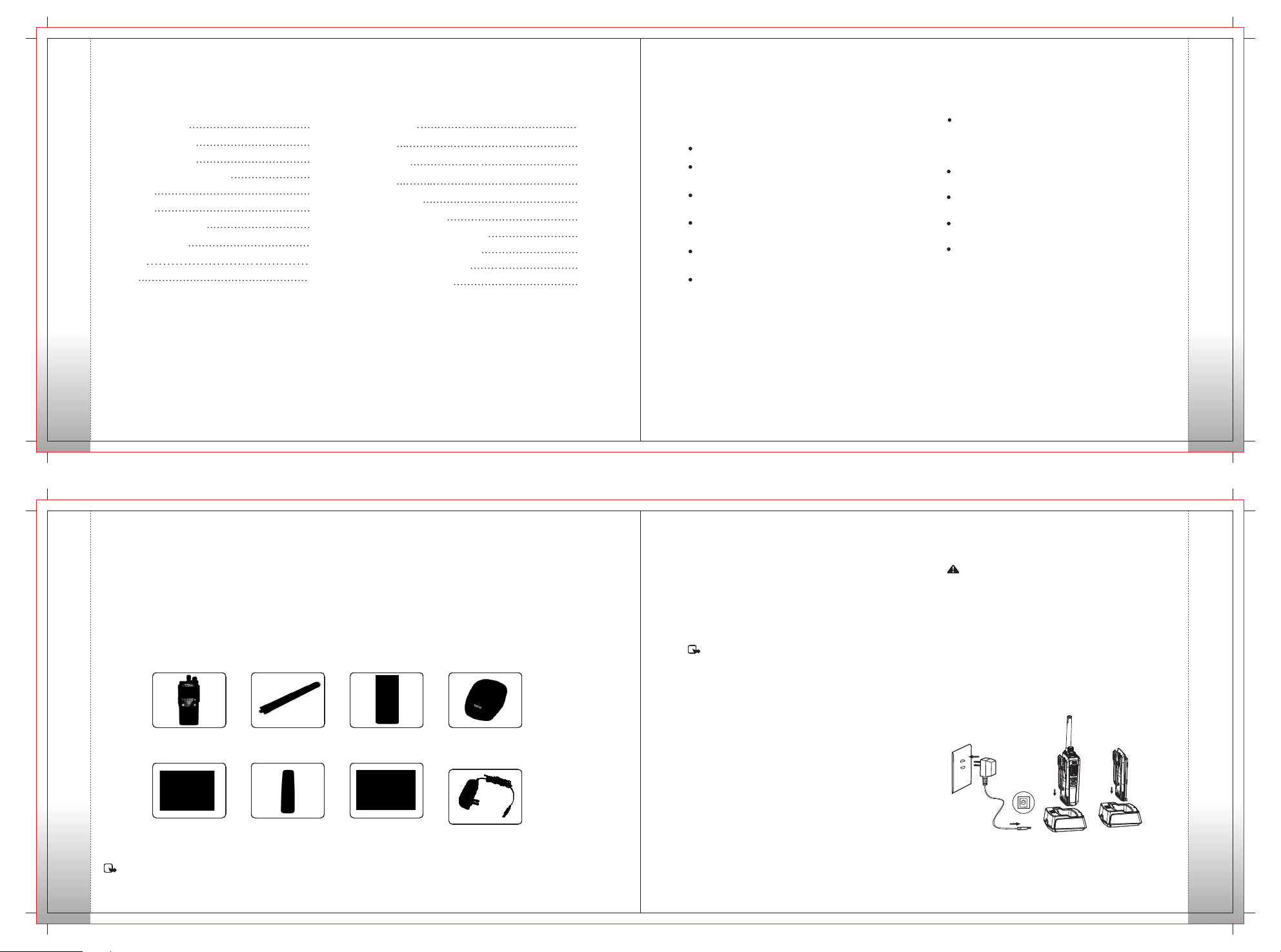
Thanks for using TR-7200 / TR-7400 . Before use, we recommend that:
First check the package for any signs of damage;
Carefully open the package and identify the items listed below;
If any items are missing or damaged during shipment, please contact your dealer.
Product Inspectionrs
digital portable radio
Items
Radio DH-9800
Qty:1
Lanyard Strap
Qty:1
Antenna
Qty:1
Belt Clip
Qty:1
Li-Ion Battery
Qty:1
User Manual
Qty:1
Charger
Qty:1
Adapter
Qty:1
Get Acquainted
Battery Information
Applicable Battery Model:
lease charge with TERA approv ed batter y; Using other
batteries may burst and cause personal damage.
Note:
1. Do not short-circuit the battery terminals or dispose the battery
in fire. Never attempt to disassemble the battery pack.
2. Charge the battery in 0-45℃ temperature. Otherwise the battery
may not be fully charged.
3. Turn off the radio equipped with battery before charge. Use the
radio while charging may interfere with charging.
4. Do not pull/plug the adapter and the battery during charging to
avoid interfere with the charging procedure.
5. When the battery power consumes quickly even if it is fully and
correctly charged, that means the battery life is over and please
replace with new battery.
6. Do not charge if the battery or radio is wet. Before charge, you
should dry it with cloth to avoid danger.
Warning:
Co ndu cti ve m e tal s s u c h as j e we l r y, k e y o r
decorating lace may result in short ci r c ui t a n d
generate a large quantity of heat w hen coming to
contact with battery ele c trode s . Treat any battery
carefully especially when placing it into pocket, wallet
or other metal container.
Charge Operation
Please charge as follows:
02
Get Acquainted
Note: Frequency is marked on the color circle at the bottom of the antenna.
03
04
Page 4
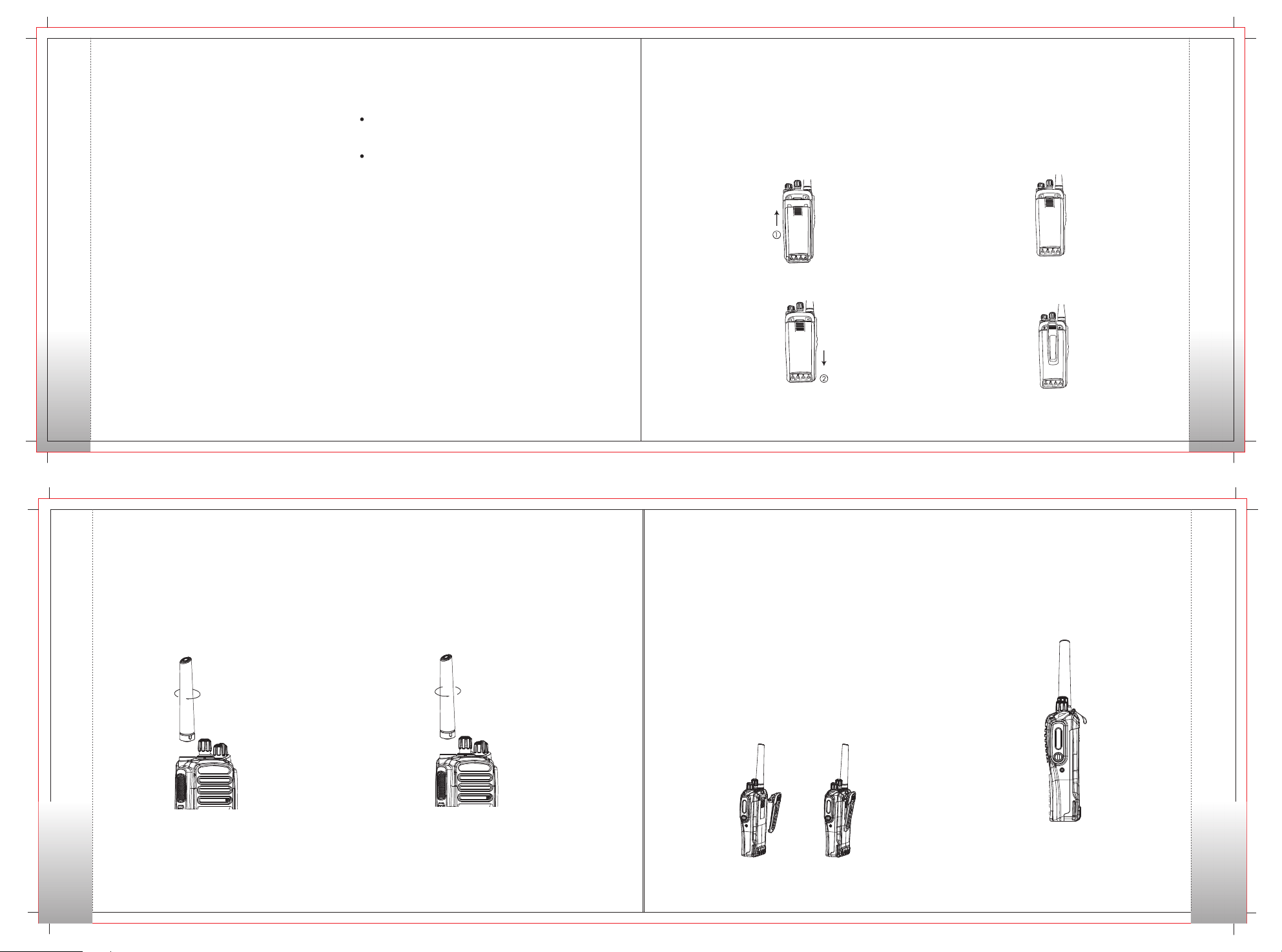
1. Turn off the radio. Plug the DC connector of adapter into the DC
jack on the rear of the charger.
2. Plug the AC connector of adapter into an AC outlet.
3. After the charger is electrified, the LED glows red for 1 second
and goes out. That means the ch arger is ready for normal
charging. If the LED flashes red, it means the charger is not ready
for battery charging.
Cautions in Charging
4. Insert the battery or radio equipped with battery into the charger.
Make sure the bat tery is in go od connection with the charger
electrode.
5. LED glows red during charging and flashed during trickle charging
because of very low battery power. And after the battery power
reached a certain mount duri ng trickl e charge, the charger
automatically turns to normal charge mode.
6. The battery is fully charged when LED glows green. The charger
stops charging automatically.
Antenna Information
Stubby antenna is suitable for short-distance communication;
thi n and l ong anten na wi ll provide best comm unication
effect. Also it is comfortable to carry on the waist.
The communication range may be shortened in rainy days or
in forest. Please make preparations for that .
Attaching and Removing
Attaching the Battery
Match the two grooves of battery with corresponding guides on
the back of the radio. And make sure the full contact and parallel
between the battery and aluminum chassis.
Then push the battery along the guide until the battery latch locks.
Removing the Battery
To remove the battery, first make sure the radio is turned off, then
push the battery latch in the opposite direction of the mark “LOCK”
to unlock it, and push the batte ry latch downwards.
Attaching/Removing the Battery
Cautions in Charging
1. The battery is not charged in factory. Please charge the battery
before initial use or after long-time storage.
2. Repeat charging 2 to 3 times will make the battery reach its
best capacity. Please replace or charge the battery if battery
power is low.
3. When the battery power consumes quickly even if it is fully and
correctly charged, that means the battery life is over and please
contact your dealer and buy new approved battery.
05
Attaching/Removing the Antenna
Attaching the antenna:
1. Insert the antenna into the connector on the top of radio by
holding the antenna at its base.
2. Rotate the antenna clockwise to fasten it.
Removing the Antenna:
Rotate the antenna counter clockwise until you can
remove it.
Push th e batt ery la tch toward s the mar k “Loc k” to loc k it.
Installing/Removing the Belt Clip
Installing Belt Clip
Match the grooves of belt clip with those on the rear of radio and
press the belt clip downwards until it is locked.
Removing Belt Clip
Use your nail or a tool to lift the metal spring piece in the belt clip
from topside and pull the belt clip upward from the battery pack.
Slide the battery away from the radio.
06
Installing Hand Strap
Thread the strap into the hole at the back of the radio
and fasten it.
Note:
Attaching/Removing the Antenna
07
1. To use belt clip, please install the belt cli p o nto the battery
before the installing of battery pack.
2. Remove the battery from th e rad io befor e the removing of
belt clip.
(Figure 1) (Figure 2)
Installing/Removing the Belt Clip
08
Page 5
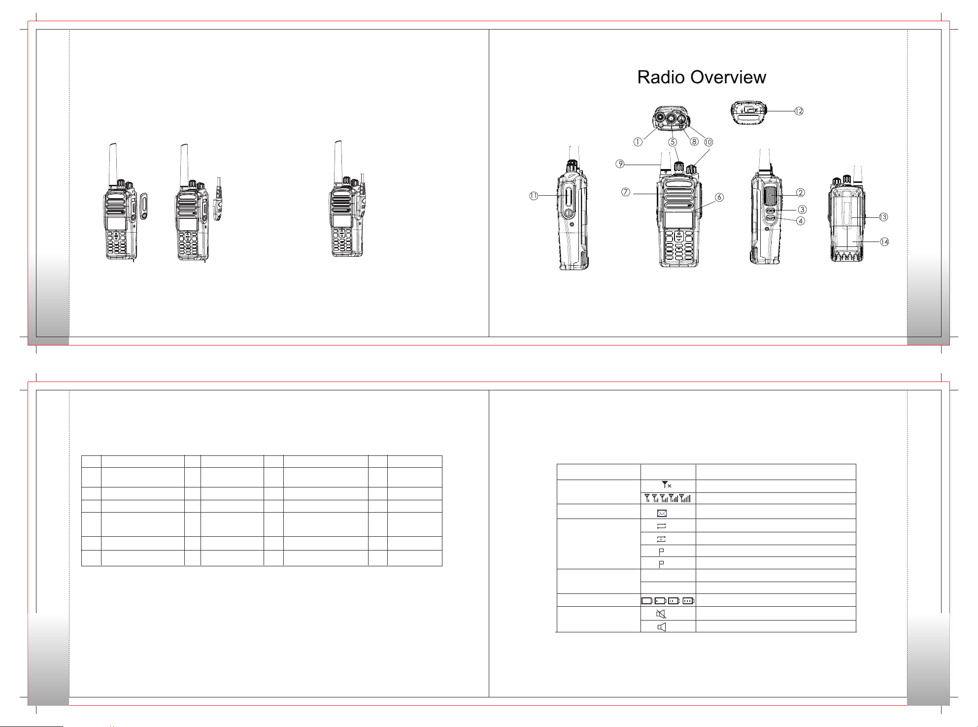
Attaching the Audio Accessory
Programming Cable
1. Remove the screw on the acces sory jack cover, open the
accessory jack cover as figure show below.
2. Align the plug with the accessory jack.
3. Tighten the screw on the plug.
Attaching the Audio Accessory
Removing the Accessory
To remove accessories, loosen the screw as figure
shown below.
Radio Overview
09
10
Status Indicators
No. No.
Part Name Part Name
Radio Overview
1 7 13
SK1(Side Key 1) LCD Display
2
PTT Key
3
SK2(Side Key 2)
4
TK(Top Key)
5
Channel Selector Knob
Microphone
No. No.
Part Name Part Name
Radio On-Off/ Volume
8
OK/Menu Key Accessory Jack
9
Speaker
Numeric Keypad
10
11
LED Indicator
12
Antenna
Control Knob
14
Back Key
15
16
Right Key/ Home
Screen Key
17
Left Key
18
Up Key
19
20
21
22
Down Key
Battery Latch
Belt Clip
Battery
LCD Icons
Icon Name
RSSI
Message Icons
Scan Icons
Tx Power Icons
Battery Strength Icons
Tone Icons
Icon
1
2
L
H
Radio Status
No signal
More bars indicate better signal strength
New Message/Unread Message
Scanning is in progress
Scanning pauses on a non-priority channel
Scanning pauses on Priority Channel 1
Scanning pauses on Priority Channel 2
Low Tx power for the current channel
High Tx power for the current channel
More bars indicate more battery power
Radio Silent is on
Radio Silent is off
Status Indicators
11
12
Page 6
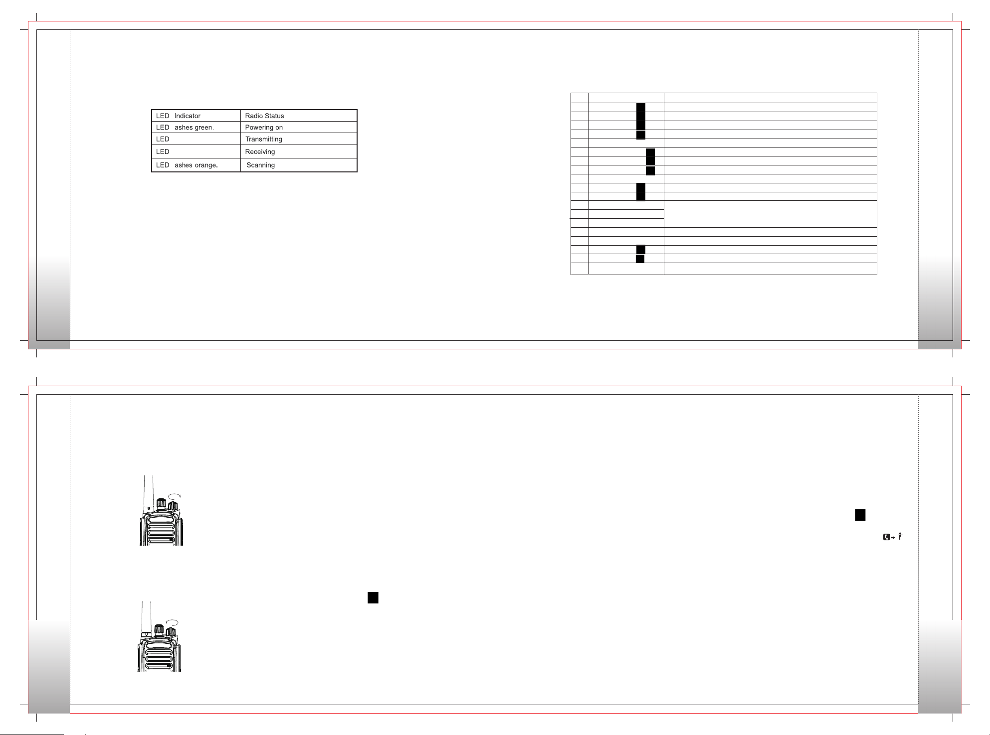
LED lndicator
The top LED indicator will help you easily identify current radio status.
LED lndicator
flas he s re d.
flas he s green .
Programmable Keys
For enhanced convenience, you may request your dealer to program the keys【SK1】、【SK2】、【TK】as shortcuts to the functions
listed below:
Shortcut Keys
No.
1
Radio Disable
2
Radio Enable
3
Radio Check
4
Alert Call
5
Adjust Power Level
6
Remote Monitor
7
Emergency On
8
Emergency Off
9
VOX
10
Message
11
Contact
12
Zone Up
13
Zone Down
14
Zone Switch
15
Keypad Lock
16
Vibration
17
Man Down
18
Squelch Off
19
Battery Power Indicator
Note: 1)Long and short press of a key can be assigned with different functions by your dealer.
2 The【TK】is programmed as the Emergency key by default, and is programmable by your dealer.)
To disable the radio of a private contact quickly
To enable the radio of a private contact quickly
To check the radio of a private contact quickly
To initiate an alert call
To change the TX power between High and Low
To remotely monitor a contact through one button press
To initiate an emergency call.
To stop the emergency call
To toggle the VOX function between on and off.
Quick access to the menu “Message”
Quick access to Contact List
Quick access to a desired zone
To lock or unlock the keypad quickly
To enable or disable Vibration function through one button press
To enable or disable Man Down function through one button press
To always unmute speaker no matter whether carrier is present or not.
To show the battery power through one button press.
Description
Programmable Keys
13
Basic Operations
Turning the Radio On/Off
Rotate the【Radio On-Off/Volume Control】knobclockwise/
counter-clockwise until a click is heard to turn the radio on/off.
Basic Operations
Adjusting the Volume
After turning the radio on, rotate the Radio On-O ff/Volume
Control knob clockwise to increase the volume, or counterclockwise to decrease the volume.
Selecting a Zone
A zone is a group of channels exhibiting the same property, and
is programmed by your dealer. The radio supports up to 16 zones,
each with a maximum of 16channels. You may select a zone
through any of the following methods.
1. Always Allow: the user can transmit all the time.
2. Through menu selection.
Go to the menu “Zone”, and use the 【Up】/ 【 Down】keys to
select your desired zone and use【OK】key to switch to the zone.
3. .
Through the function keys
You may quickly toggle to you desired zone by pressing the
programmed【Zone Up】/【 Zone Down】/【Zone Switch】
key.
Note: This feature is available for digital channel only.
Selecting a Channel
Rotate the【Channel Selector】knob to select a desired
channel.
Users can set the “Tx Admit” feature for each digital
channel via programming software. This feature prevents
users from transmitting on channels that are already in use.
1. Always Allow: the user can transmit all the time.
2. Channel Free: the radio can transmit only if the channel is
free.
3. Color Code Free: the radio can transmit only when the
channel is free or the color code is not matched.
Note: This feature is available for digital channel only.
Digital/Analog Switch
Each channel can be programmed as either analog channel or
digital channel. If the current zone includes both analog and
digital channels, you may quickly switch betwe en digita l and
analog through the 【Channel Selector】knob.
Locking/Unlocking the Keypad
When the keypad is not in use, y ou ca n lo ck th e k e y p a d t o
pre ven t a cci denta l keyp ad ope rat ion. Thre e m e t h o d s ar e
available for you to lock or unlock the keypad:
1. Through key combination
Use“【OK】+【*DEL】”to lock or unlock the keypad.
2. Through the function key
Press the programmed Keypad Lock key to lock or unlock the
keypad.
3. Through menu selection
Go to Settings -> Basic Setting -> Keypad Lock, and then select
On or Off.
Keypad Lock On:
The keypad will be locked automatically if no operation is made for
the preset time period.
Keypad Lock Off:
The keypad will not be locked automatically. However, you can
lock or unlock the keypad via the key combination or Keypad
Lock key mention above .
Call
Transmitting a Private Call
You may transmit a Private Call through any of the followi ng
methods. When transmitting a Private Call, the icon “ ”
will appear.
Transmitting a call to the preset contact
In standby mode, pressing PTT key will transmit a n indi vidu al
call to the contact (a Private Call number) preset for the current
channel.
Note: Your dealer may preset a contact for each digital channel.
The preset contact could be a Private Call number, a
Group Call number or an All Call number.
14
Call
15
16
Page 7
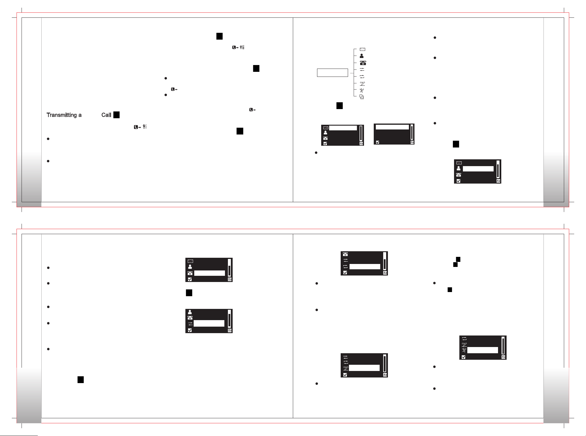
Transmitting a call through Contact List or Call Logs
1) Go to Contact, or go to Call Logs ->Call List
Missed List
Call
2) Use the Up/Down key to select the Private Call number you want
to call.
3) Hold down PTT key to transmit a Private Call to the selected
contact.
->Outgoing/Incoming/
Transmitting a call through Manual Dial
1) Go to Manual Dial.
2) Input a Private Call number you want to call.
3) Press PTT key to transmit a call.
Note: If the keypad input function is enabled by the dealer via
the programming software users can input a Private Call
number though Numeric Keypad.
Group
You may transmit a Call through any of the fo llo win g
methods. When transmitting a Group Call, the icon“ ”
will appear.
Transmitting a call to the preset contact
In standby mode, pressing PTT key will transmit a group call
to the contact (a Group Call number) preset for the cur re nt
channel.
Transmitting a call through Contact List or Call Logs
1) Go to Contact .
2) Use the Up/Down key to select the Group Call number you
want to call.
3) Hold down PTT key to transmit a Group Call to the selected contact.
17
Gro up
Transmitting an All Call
Methods are the same as those in Transmitting a Group Call
When transmitting an All Call, the icon“ ” will appear.
Note:
You can transmit an All Call only when it is enabled by your dealer.
Receiving and Responding to a CallGroup
Receiving an All Call
When an All Call is rec eive d, yo ur radio will display the
icon .
Responding to a Call , af ter a Call is
received, you may press the PTT key within the pr ese t
time period to call back. If you do not respond to a received
Private Call, the radio will display the missed call icon“ ”.
Group Group
Note: You cannot respond to an All Call.
Make a Call on Analog Channels
To transmi t on an anal og chan nel , h old do wn the PTT and
speak into the microphone. To receive, release the PTT.
Note: To ensure an optimal volume for the receiving radio, hold the
radio approximately 2.5 to 5 centimeters away from your mouth
during transmission.
Menu Navigation
Message
Contact
Main Menu
Message
To access this item, press the Menu key in idle mode and then
select “M essa ge”, or press the shortcut key for Message
directly.
Message
Contact
Manual Dial
Inbox
To access this item, press the Menu key in idl e mode an d then
select “ Mess age” , or press the shortcut key for Messag e
directly.
For each message, you can choose to perform any of these operations:
Reply/Forward/Edit/Delete. To delete all messages in the Inbox, select
“Message→Delete→Inbox”.
Manual Dial
Call Logs
Scan
Program
Settings
Zone
Inbox
New Msg
Outbox
New Msg
You can create your desired text messages (150 characters at
most) and send it to an individual user or to a talk group.
Outbox
The Outbox can save up to 15 sent messages. Whe n th e Outbox
is full, the oldest entry will be overwritten by the latest one auto
matically.For each message, you can choose to perform any of these
operations: Resend / Forward / Edit /Delete. To delete all messages
in the Outbox, select“Message→Delete→Outbox”.
Quick Text
Under this option there are some text messages (15 entries at
most) preset by your dealer. You can choose to edi t and s end
any entry.
Drafts Box
The Drafts Box can save up to 15 messages. Users can re-edit
or send the message saved in the Drafts Box.
Contact
To access this item, press Menu key in idle mode and then select
“Contact”.
Message
Contact
Manual Dial
Menu Navigation
18
You can save up to 64 entries in the list. To access this. item,
select “Contact” or press the shortcut key for Contact List.
Detail
You can view details of each contact.
Menu Navigation
New Contact
You can add a Private Call contact to the contact list. The number
and alias of each contact must be unique, and the available
number range is 1-16776415.
Editing a Contact
You can edit the number and alias of each Private Call contact.
Deleting a Contact
You can delete a Private Call contact. However, please note that
you can not delete the contact when there is only one entry left
in the list.
Sending Msg
Users can send a message to a contact.
You can enable Radio Check/ Alert Call/ Remote Monitor/ Radio
Disable/ Radio Enable of a Private Call contact.
Manual Dial
To access this item, press the【Menu】key and then select
“Manual Dial”.
19
You can manually input the Private Call number for calling.
Message
Contact
Manual Dial
Call Logs
To access this item, press the Menu key in idle mode and then
select “Call Logs”.
Contact
Manual Dial
Call Logs
This radio can save up to 20 entries in the Outgoing List, Incoming
List and Missed List respectively (only for private call list). When
the memory for call logs is full, the oldest entry will be overwritten
by latest one automatically. After accessing a list and selecting
an entry, you can perform any of these operations: hold down the
PTT key to initiate a call, view, send a message or del ete it. To
delete all entries in Outgoing List, Incoming List and Missed List at
a time, select “Call Logs→Delete→Outgoing /Incoming /Missed”.
Scan
To access this item, press the【Menu】key and then select
“Scan”.
Manual Dial
Call Logs
Scan
Scan On/Off
The fu nction “Scan ” allows you to li sten to commun ication
activities on other channels so that you can keep a close track
of your team members. This option is used to enable or disable
the function.
Scan List
The function “Sc an” allows you to listen to communication
activities on other channels so that you can keep a close track
of your team members. This option is used to enable or disable
the function.
Program
To access this item, press the【Menu】 key and then select
“Program”.
Call Logs
Scan
Program
Channel
You can optimize your radio performan ce by custom izing
related parame ters ac co rd in g to actua l needs a nd y ou r
preferences.
Frequency:to set the Rx frequency and Tx frequency of current
channel Slot :to select the Tx slot
Color Code :to set the co lor code val ue for cur rent digital
channel (available range: 0-15)
Radio
Radio ID :to view and change radio ID (this item is restricted by
its available range “1~16776415”and the program software).
Settings
To access this item, press the【Menu】key and then select
“Settings”. You can optimize your radio performance by
customizing related parameters according to actual needs
and your preferences.
Scan
Program
Settings
Device Information
With this option, you can view the basic information of. your radio,
including radio ID, software version, firmware version, model number.
Parameter Setting
TOT
With this option you can set the duration that the radio can
Settings
20
Page 8
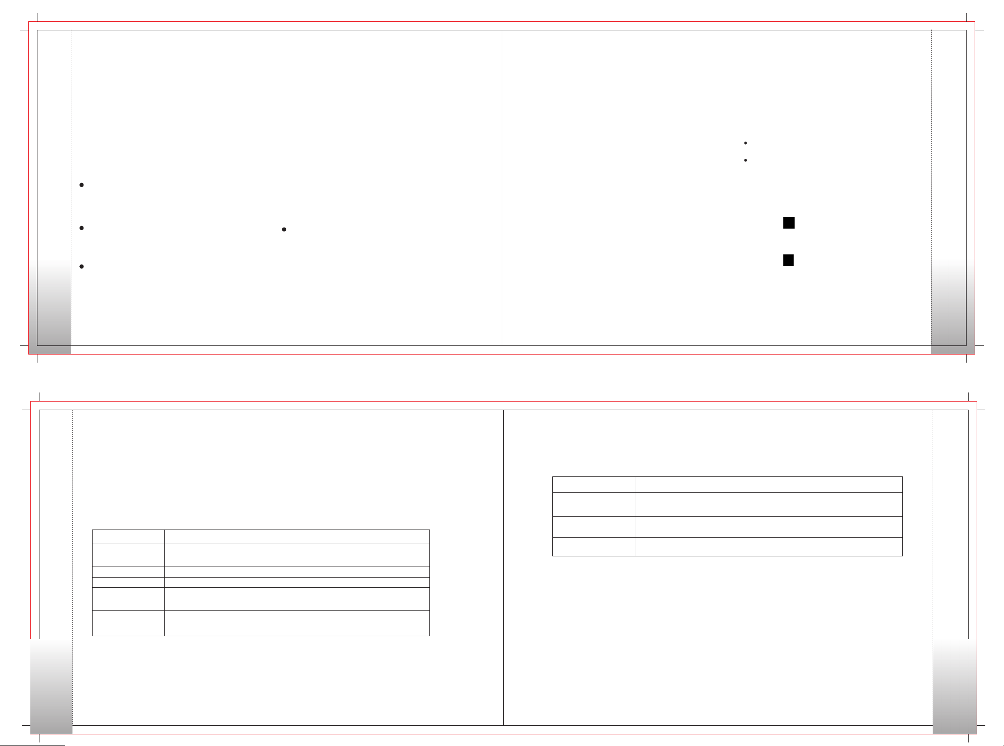
continuously transmit. The purpose of this feature is to prevent
any user from occupying a channel for an extended period. If
the preset time expires, the radio will automatically terminate
transmission and keep beeping. To stop beeping, please release
the PTT key. You must wait for a certain time period before you
Settings
can press and hold down the PTT key to transmit again.
Note:This feature is null in Emergency mode.
Tx Power
This option allows you to set transmit power level. Alternatively,
you can change the power level by pressing the shortcut key for
Adjust Power Level.
There are two levels availa ble: High (i ndi cated by H ) and
Low (in dicat ed by L ). Hig h po w er l eve l en a bl es y o u to
communicate with further team members.
VOX
This option allows users to configure the VOX function.
When enabled, this function allows users to speak into the radio
directly without pressing PTT key.
Vibration
This option allows users to enable vibration alert for messages,
private calls, alert calls and so on.
Tone
To set tones for your radio, you can set the following tones:
Radio Silent
To set whether the radio will give tone indication. If Silent on is
selected, all alerts will be off.
Keypad Tone
To set whether the radio will give tone indication when there are
keypad operations and to set the volume of the tone.
Low Battery Tone
To set whether the radio will give tone indication when the battery
power is low and to set the volume of the tone.
Message Tone
To set whether the radio will give tone indication when receiving
a message and to select a ring .
Private Call Tone
To set whether the radio will give tone indication when making a
private call and to select a ring.
Group Call Tone
To set whether the radio will give tone indication when making a
group call and to select a ring.
Basic Settings
Language
To set the language in which all interface information s displayed.
At the moment, this radio only supp ort s two languages:
Simplified Chinese and English.
Keypad Lock
To set whether to enable auto keypad lock.
Display Setting
Backlight:To set the backlight parame ters. There are three
options available: On, Off and Timer.
Backlight Time:The backlight will be off automatically upon
expiration of the time set here. The available range is 5-15s.
Brightness: To set the display brightness. You can increase or
lower it using 【Up】/【Down】 key.
Keypad LED
To set whether to enable keypad LED. When “On” is selected and
there is no keypad operation in 5s, the keypad LED will be off.
Zone
To access this item, press the【 Menu】 key and then select
“Zone”.
This radio supports up to 16 zones. You can use this menu to select
yo u r d e si red z o n e o r y ou can use pro gra m med Zone
Up】/ 【Zone Down】/【Zone Switch】key to switch to your
desired zone.
Functions and Operations
Scan
The feature “Scan” allows you to listen to communication activities
on other channels so that you can keep a close track of your team
members.
Operation:
1、To enable the feature, you can se lect “On”fro m th e
menu “Sca n”; or sw it ch to a channel for wh ic h t he
feature “Auto Scan”is enabled via the programming
software.
2、Af ter the fea tur e is e nab led , yo ur r adi o wi ll s c an
according to the scan list set for the channel on which
scanning starts. The scanning process is as follows:
During scanning, LCD displays icon , and LED flashes
orange.
When activities are detected on a cha nn el , the radio
will stay on the channel to receive current activities.
If your radio stays on a non-priority channel, LCD will
display icon ; If on Priority Channel 1 or Priority Channel
2, LCD will display icon or icon respectively.
To exit the scanning process, you can select “Off” from the
menu “Scan”.
Squelch Off
If the feature “Squelch Off” is enabled, your radio’s speaker
will keep unmuted no matter whether carrier is present.
Emergency
If the feature “Squelch Off” is enabled, your radio’s speaker
will keep unmuted no matter whether carrier is present.
1、Digital Emergency
In case of an emergency, you can use the feature to ask
for help from your companion or control center.
Basic Operations
21
The Emergency process has the highest priority.
You can make emergency operation even when your radio is transmitting or receiving.
To enable the feature on a channel, an emergency system must be assigned to the channel via the programming software.
In addition, the Emergency type and Emergency mode are settable via the programming software.
Emergency Mode
Emergency Type
There are five Emergency types available. You can select one of them via your dealer.
Emergency Type
Siren Only
Regular
Silent
Silent w/ Voice
Alarm w/ Siren
The radio will emit siren locally, but will not transmit any emergency
signal to the control center.
The radio gives visible and audible indications during emergency state.
The radio gives no indication during emergency state.
The radio gives no indication during emergency state, but will unmute
its speaker once it receives a call.
The radio transmits the emergency signals to the control center first,
and then gives siren locally with visible indication.
Description
Emergency Mode
Your radio supports three Emergency modes. You can select one of them via your dealer.
Emergency Mode
Alarm
Alarm w/ Call
Call Only
The radio only sends emergency alarm request upon emergency
activation.
The radio sends emergency alarm request before the emergency call
upon emergency activation.
The radio only transmit Emergency call upon emergency activation
2、Man Down
To set this feature via programming software. Once this feature is activated, the radio will enter Man Down status automatically
when it tilts to the preset gradient. Or you can press the shortcut key to enable or disable this function.
3、 Lone Worker
This feature triggers off the Emergency mode if the user fails to have any Lone Worker response operation on the radio for
a certain time period. This feature is designed for persons who work alone.
If the user cannot operate the radio within the preset time due to emergency, the radio will make an emergency al arm
automatically to inform user’s colleagues or the control center for help.
Description
22
Emergency Mode
23
24
Page 9
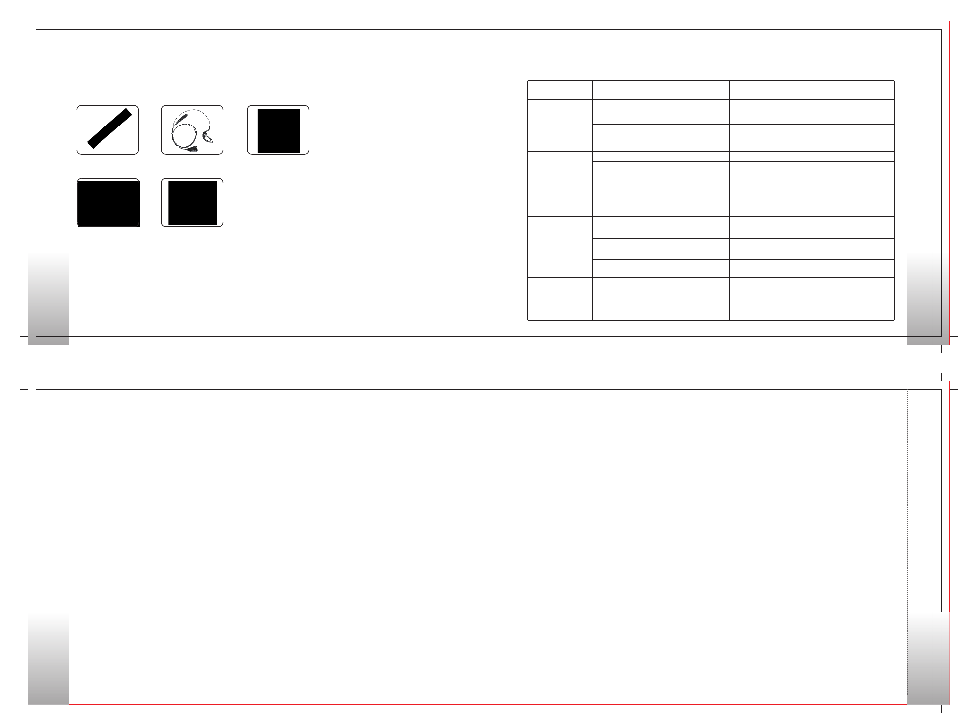
Optional Accessories
Optional accessories are available according to your requirements. All accessories with good quality will ensure you clear communication and
outstanding performance.
Optional Accessories
Optional UHF Antenna
USB Programming Cable Heavy Duty Speaker Mic
25
G-Hook Lapel Mic Covert Clear Acoustic
Tube Earphone MIc
Care and Maintenance
Question and Answer
Phenomena
The battery may be improperly installed.
The equipment can
not be powered on.
During receiving
signals, the voice
is weak,
discontinuous or
totally inactive.
You can not
communicate with
other members.
Irrelevant
communications or
noises are heard
on the channel.
The battery may run out.
The battery may suffer from poor contact
caused by dirtied or damaged battery
contacts.
The battery strength may be too low.
The volume may be set to a low level.
The antenna may get loose or may be
improperly installed.
The speaker may be blocked or damaged.
The frequency or signaling may be
inconsistent with that of other members.
The channel type (digital/analog) may be
set inconsistently.
You may be too far away from the group
members.
You may be interrupted by radios using the
same frequency.
The radio may not be set with any signaling.
Analysis
Solution
Remove the battery and attach it again.
Recharge or replace the battery.
Clean the battery contacts. If the problem can not
be solved, contact your dealer or authorized service
center for inspection and repair.
Recharge or replace the battery.
Increase the volume.
Power off the radio, and re-install the antenna.
Clean surface of the speaker. If the problem can not
be solved, contact your dealer or authorized service
center for inspection and repair.
Set your TX/RX frequency and signaling to the same
as that of other members.
Make sure all members are on the same digital/
analog channel.
Move towards other members.
Change the frequency, or adjust the squelch level.
Set signaling for all member radios to avoid
interference at the same frequency.
Care and Maintenance
26
Service and Support
TERA Radio provides warranty and non-warranty support for this radio and accessories.
Warranty and Repair Services
1. TERA two-way radio body has an industry leading 2-year warranty. Radio accessories(battery, charge adapter, charger and
antenna, spe aker mics) include a 6 month war ran ty from date of purchase.
2. The radio warranty of 2-years is in effect from the original purchase date on the sales receipt or invoice.
Service and Support
3. Repair or Replacement is available provided the original purchaser’s sales receipt copy is included when the radio or accessories
are sent in for repairs.
4. Replacement and repair or radios and accessories is provided at the discretion of TERA radio.
5. All repaired parts have its own warranty of 90-days from the repair date or the original radio warranty depending on the longer one is valid.
6. The warranty is only valid using this radio for normal use. And guaranty is unavailable under such conditions: dissembling or modifications
damages caused by outside force and usage of unapproved accessories or antenna, not according to the user manual and so on.
7. Warranty is void if the TERA label or Serial Number label is missing or torn off.
Cautions
1. Read the user manual before use.
2. Do not use the radio with damaged antenna. Use the radio only with standard antenna.
3. Turn off the radio in potential dangerous environment.
4. Avoid the contact between the battery and t he metal oily or corrosive objects.
5. Do not dip the radio or battery into water or throw them in fire.
6. Use the radio only with standard battery, adapter charger and earphone.
27
Terms of Warranty
1. TERA two-way radio body has an 2-year guarantee; accessories (battery, charge adapter, charger and antenna), earphone 6 months.
2. Only the original purchasing sales receipt or valid dealer’s invoice (The invoice will give clear indication of items purchased and the
radio serial-number, and purchasing date).
3. Replacement and repair is available subject to the presentation of original purchasing invoice in case that the radio cannot work
normally as the instruction says within 30 days from the purchase date. (Note that there must not be visible abrasion on radio body and
accessories.
4. Repair of accessories (battery, adapter, charger and antenna) is available to the presentation of original purchasing invoice.
5. The cost of materials and labor for repair are covered in warranty.
6. Warranty is void in case that the TERA mark or the serial-number mark is torn off.
7. Warranty is void in cases below:
1) Beyond the warranty period;
2) Defects or damages under abnormal use;
3) Defects or damages because of mis-operation, accident and carelessness;
4) Defects or damages because of incorrect testing, operation, repair, installation, reconfiguration or adjustment;
5) Defects or damages to antenna because of non-material or non-processing problems;
6) Defects or damages because of unauthorized repair and disassembling;
7) Product that the serial-number marks is torn off or unable to identify;
8) Product with unclear purchasing date on original sales receipt.
9) Battery under such conditions:
a. Any damages or unsealing to the battery pack;
b. Defects or damages to battery because of charging with improper equipment or use beyond regulated maintain condition;
10) Abrasion under normal use.
Terms of Warranty
28
Page 10
Warning Noes
Every effort has been made to ensure that the information in this document is complete, accurate, and up to-date. TERA Radio assumes
no responsibility for the results of errors beyond its control. The manufacturer of this equipment also cannot guarantee that changes in the
equipment made by non-authorized users will not affect the information in it.
FCC Licensing Information
This TERA radio operates on Commercial / Land Mobile frequencies which require a license from the Federal Communications Commission (FCC)
for business, personal, education and recreational use. To obtain forms, call the FCC forms hotline at: 1-800-418-3676 or go to
FCC Licensing InformationWarning
http://www.fcc.gov.
For questions concerning commercial licensing, contact the FCC at 1-888-CALL-FCC(1-888-225-5322).
Safety
The TERA handheld transceiver has been carefully designed to provide you with years of safe, reliable operation. As with all electrical
equipment, however, there are a few basic precautions you should take to avoid hurting yourself or damaging the radio:
• Read the instructions in this handbook carefully. Be sure to save it for future reference.
• Read and follow all warning and instruction labels on the radio and owner’s manual.
• Do not carry the transceiver by the antenna. This may damage the antenna or antenna terminal. Grasp the handheld by its base (not the
antenna) when you need to place or remove it.
• Do not keep the radio with the antenna very close to, or touching exposed parts of the body, while transmitting. TERA radios will perform
best, if you speak 2-4 inches away from the microphone and the radio is vertical.
• Be sure the “PTT” key is not pressed when you do not need to transmit.
• Do not operate the radio near unshielded electrical blasting caps or in an explosive atmosphere.
• Do not transmit without the antenna fitted on the radio. Though it is provided with a protection, it may damage the TX output final stage.
• Respect the environment conditions. The radio is designed to be used in heavy environments, however avoid exposing it to extre mely
hot or cold temperature (out of the range between –20 to +140°F). Do not expose the transceiver to excessive vibrations as well as dusty
or rainy locations.
• Never try to disassemble or service the radio by yourself (aside from the routine maintenance described in this handbook). It may cause
damage to the radio transceiver and void your warranty requiring extensive repair work. Always contact your local dealer for assistance.
• Use only authorized accessories. Using non TERA radio brand accessories may seriously damage your handheld transceiver and void
your warranty.
• Do Not spill liquid of any kind into your radio. If the transceiver gets wet, immediately dry it by a soft and clean cloth.
• Switch the radio off before you clean it. Follow the directions described in the paragraph “Care and maintenance”.
• Handle the battery properly. Never place the LI-ion battery in your pocket or purse with loose coins. This could result in short circuiting
the battery.
• Be certain that your power source matches the rating listed for the supplied battery charger (AC adapter). If you are not sure, check with
your authorized TERA dealer
• Avoid damaging the power cable of the battery charger. Do not step on or place anything on it as this could result in a damaged charger
power cord. This product complies with the requirements of the Council Directives 89/336/EEC and 73/23/EEC on the approximation of
the laws of the member states relating to electromagnetic compatibility and low voltage..
Safety
29
30
FCC Caution:
Any Changes or modifications not expressly approved by the party responsible for compliance could void the user's
authority to operate the equipment. This device complies with part 15 of the FCC Rules. Operation is subject to the
following two conditions: (1) This device may not cause harmful interference, and (2) this device must accept any
interference received, including interference that may cause undesired operation.
31
 Loading...