

Page 1

MCPS2000 Operations Manual
1 Introduction
This chapter introduces the MCPS2000 Series of Multi Carrier Power Amplifier
(MCPA) Systems. It describes structure of this manual and introduces the different
MCPS2000 Series amplifiers.
1.1 About this Manual
This Manual describes how to install, operate, and maintain the MCPS2000 series of
amplifiers. It is arranged in chapters.
Chapter 1, Introduction, introduces the systems in the MCPS2000 family and their
main features and describes how the system documentation is organized.
Chapter 2, Installation and Operation, describes how to install the MCPS2000
amplifier and place the amplifer in service.
Chapter 3, Troubleshooting, describes how to diagnose faults using the indicator
LEDs and status/alarm messages.
Chapter 4, Field Service Procedures, describes how to perform routine maintenance
and install new field-replaceable modules in the MCPS2000 amplifier.
The Specifications Appendix details the electrical, mechanical, and environmental
specifications met by this MCPS2000 amplifier, including the Connector Pinouts and
Interface Protocols used in the front panel diagnostic port and the optional base
station alarm and control interfaces.
1.2 Introduction to the MCPS2000 Family
The MCPS2000 is a modular, ultra-linear cellular-frequency amplifier system
providing up to 350 Watts (total) of output power. Designed for maximum flexibility
and reliability, the MCPS2000 can increase the range or capacity of both new and
existing base stations.
Modulations
The MCPS2000 can amplify any number of signal carriers using AMPS, CDPD, IS136 TDMA, or IS-95 CDMA modulation up to the maximum rated system output
power.
Spectrian Proprietary
This document contains proprietary information of Spectrian, Inc. and may not be
used or disclosed except in accordance with applicable agreements.
Copyright © Spectrian, Inc. All rights reserved.
1
Page 2

Introduction to the MCPS2000 Family
Modularity
The MCPS2000 family is designed for operation with 1 to 4 amplifier modules, each
providing 100 Watts of RF output power (up to 90 Watts effective output after
combining losses).
Installation
The MCPS2000 housing is an 8RU shelf. Mounting kits are available for installation
in 23-inch, 600mm, 24-inch, or 25-inch equipment racks.
RF Interfaces
It has a single RF input for the combined input signals, and a single RF output to t he
transmit filter.
Alarms and Control
The MCPS2000 provides status information through front-panel LED indicators and
an RS-232 status port. Status information can be viewed through a front-panel RS232 port using either a VT-100 terminal emulation program or Spectrian’s Graphical
User Interface program.
The MCPS2000 can also be optionally equipped with additional alarm and control
interfaces, including dry-contact or TTL alarm connections and RS-485 or RS-422
interfaces to network operations and administration systems.
Reliability
The MCPS2000 is designed to enable system maintenance without removing the
amplifier from service. The amplifier and system control modules can be hotswapped during operation without affecting calls in process. The amplifier modules
are designed so the cooling fans can be refit in the field by qualified service
technicians, greatly reducing service shipping costs and turn-around time.
1.2.1 MCPS2000 Systems Modules
A fully-equipped MCPS2000 consists of a rack-mounted shelf containing up to four
RF modules, an Alarm Management Module, and an internal divider/ combiner.
RF modules
The RF modules are ultra-linear amplifiers optimized for high power amplification
of cellular signals. After combining losses, each RF module provides up to 90 Watts
of RF output power.
Amplifier Management Module
The Amplifier Management Module contains the system control and alarm
management logic and the interface to external operations and control systems.
Divider/Combiner
The divider/combiner allows the four RF modules to function as a single system.
The divider/combiner has an active architecture, which automatically reconfigures to
minimize combining losses if a RF module should fail.
2
Spectrian Proprietary -- See notice on first page
MCPS2000 Operations Manual
Page 3

Introduction
Major Equipment Specifications for the MCPS2000
Electrical Specifications Specification @ 25ºC
Frequency Range 869 - 894 MHz
Average Power¹ into 50 Ohms 100W (50 dBm) to 350W (55.4 dBm)
Intermodulation Distortion (IMD) -65 dBc with AMPS and/or TDMA IS-136, or IS-97
CDMA dual mo de input sources under nominal
CDMA Adjacent Channel Power
3
@ 881 MHz, 100W Output < -60 dBc, 1.98 MHz offset, 30 KHz res bandwidth
Receive Band Noise -30 dBm/30 kHz bandwidth
Carrier Spacing (AMPS/TDMA) 60 KHz min., 25 MHz max.
Power Output Stability for Single Frequency ± 0.5 dB under nominal conditions
Operating Bandwidth up to 25 MHz
Gain Factory set, 30 to 60 dB, 85 dB with optional preamp
Gain Flatness vs. Frequenc y ± 0.5 dB (over all temps)
Gain Variation over Temp @ Any Inband Fr equency ± 1 dB
Forward Power Sample Port Gain -50 dB typ.
Input/Output Port Return Loss -15 dB min.
Second/Third and Greater Harmonic Output -13 dBm/-20 dBm max.
DC Input Voltage Range 26 to 28
DC Input Current @ 27VDC (max) 100W single RF module – 42A
1
Power levels at the output of the system combiner will vary depending on the configuration.
2
Reduced power performance over 21-26V. Full spec performance (22-30V) available with optional DC/DC converter.
3
Measured at the RF module out put connector and in acco rdance with IS-97.
conditions
< -45 dBc, 750 KHz offset, 30 KHz res bandwidth
2
VDC
175W two RF modules – 87A
260W three RF modules –130A
350W four RF modules – 170A
Mechanical Specifications
Operating/Storage Temperatures 0ºC to 50ºC/-40ºC to 85ºC
Size, 4 module system, mounting ears excluded (D x W x H)
17.72 x 21.56 x 13.97 in. max
(450 x 547,62 x 354,84 mm max.)
Weight, 4 module system Installed: approx. 230 lbs (105 kg)
Shipping: approx. 270 lbs max. (125 kg)
Heaviest Module: <45 lbs max. (20 kg)
Connectors RF Input(s): SMA (F)
RF Output(s): N (F)
Maintenance Port: RS232
Alarms Port: RS422
DC Inputs: 10-32 and ¼-20 threaded lugs
DC Ground: ¼-20 threaded lugs
RF Output Sample Port: SMA (F)
Indicators AMM: DC On, Alarm LEDs
MCPA Modules: DC On, Enable, Alarm, Fan LEDs
MCPS2000 System Operation 3
Spectrian Proprietary -- See notice on first page
Page 4
Introduction to the MCPS2000 Family
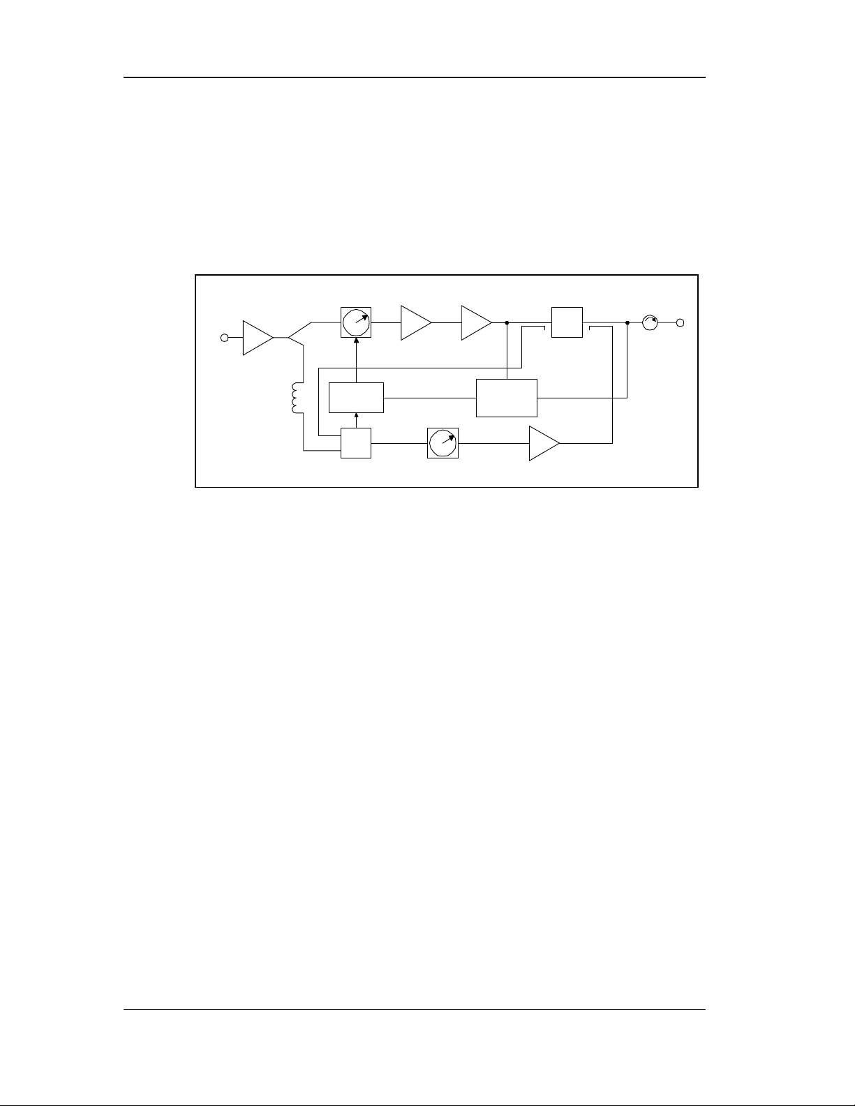
1.2.2 MCPS2000 Functional Description
To achieve the high level of linearity required to support multiple cellular carriers at
the minimum cost, the RF modules in the MCPS2000 use a single loop feed-forward
correction architecture with two amplification loops – the main loop, containing t he
main amplifier, and the error loop, containing the error amplifier. The combination
of the two loops results in a signal in which the distortion products have been
cancelled, enabling highly linear operation of the amplifier.
Preamplifier
RF Input
Delay
Line
1.2.2.1 Main Loop
The output of the main amplifier contains both the desired signal and Intermodulation Distortion (IMD) products. This signal is coupled off and combined with
the desired signal coupled off the preamplifier. The relative delay and phases of
these signals are adjusted so they combine to cancel out the desired signal, creating
an error signal composed of only the main amplifier IMD products.
1.2.2.2 Error Loop
Main
Vector Mod
Cancellation
Controller
Driver
Amp
Main
Amp
Pilot
Generator /
Reciever
Σ
Carrier
Cancellation
RF Module Functional Block Diagram
Error
Vector Mod
Error
Amp
Output Module
Delay Filter
τ
RF Output
The error signal is amplified in the error loop and then combined with the output of
the main amplifier containing both the desired signal and distortion products such
that the distortion products cancel. The error loop provides the adjustments
necessary so that the amplitude, phase and delay of both signals result in the desired
cancellation.
4
Spectrian Proprietary -- See notice on first page
MCPS2000 Operations Manual
Page 5

Installation and Operation
2 Installation and Operation
2.1 Introduction
This chapter describes how to install, set up, and operate an MCPS2000 series
amplifier in a base station. The described installation verification checks should be
performed following installation of the MCPS2000 and after major maintenance or
repairs have been completed.
The main installation steps detailed in this procedure are as follows.
• Installation Planning
• Installation Preparation
• Rack Installation
• Cable and Wire Installation
• Verify Installation
• Power-Up the MCPS2000
• Determine Required RF Input Power
• Set RF Input Power for each Channel
2.1.1 Safety Information
Please read and understand the instructions and warnings in this section and at the
beginning of this manual before handling or unpacking the MCPS2000 modules.
The MCPS2000 is designed to be installed by trained and qualified technicians.
Each MCPS2000 amplifier module and the shelf subassembly weigh 20 kgs (44 lbs);
when crated for shipping an MCPS2000 system can weigh in excess of 100 kgs (220
lbs) and be unbalanced. To avoid injuries or damage, use care and obtain assistance
when lifting a crate containing MCPS2000 components.
MCPS2000 System Operation 5
Spectrian Proprietary -- See notice on first page
Page 6

Installation Planning
2.2 Installation Planning
It is important to ensure all planning and site preparation is complete prior to
beginning to install the MCPS2000. This section describes some installation
considerations and the information required before beginning the installation
procedure.
2.2.1 Site Planning Guide
For each MCPS2000 cell site installation, there must be a Site Planning or Site
Engineering guide giving the detailed information on the site considerations, rack
installation, cable connections, and Radio Parameters.
2.2.1.1 Site Considerations
Intended Installations
The MCPS2000 is intended for installation only in restricted access areas (dedicated
equipment rooms, equipment closets, or the like) in accordance with Articles 110-16,
-17, and -18 of the National Electrical Code, ANSI/NFPA No. 70.
Weight
The MCPS2000 shelf and each RF module weigh approximately 20 kg (44 pounds);
the fully equipped system weighs 100 kg (220 pounds). The system must be
installed, using the appropriate mounting kit, into a rack capable of supporting the
unit, and located on a floor or surface capable of supporting the combined weight of
the rack, the MCPS2000, and the installer or technician.
Floor Covering
If you intend to use a floor covering under the MCPS2000, avoid combustible
materials, industrial carpeting, or materials that will permit generation of
electrostatic charges.
Illumination
The MCPS2000 is designed to be installed and serviced under normal workroom
lighting. During installation, room lighting must be bright enough to allow reading
instructions and inspection of modules, but not so bright as to interfere with viewing
the status LED indicators on the front panel. The MCPS2000 should be oriented or
shielded so that direct sunlight does not fall upon the front panel.
Fire Protection
Spectrian recommends that the MCPS2000 installation site be equipped with smoke
detectors and an automatic fire-extinguishing system. In addition, for personnel
safety, the site should be equipped with a portable halogen or CO
fire extinguisher.
2
Altitude
When installing the MCPS2000 above 5000 ft (1542 m), derate the maximum
operating temperature by 2° C per 1000 ft (304 m) above 5000 ft.
Ventilation
The MCPS2000 requires unrestricted airflow around the MCPS2000. The site must
be ventilated or air-conditioned so that ventilation air does not exceed 50° Celsius.
6
Spectrian Proprietary -- See notice on first page
MCPS2000 Operations Manual
Page 7

Ambient air quality
The MCPS2000 should be installed in a location that is free of airborne dust and
toxic or corrosive fumes.
Vibration and Noise
The MCPS2000 tolerates moderate levels of vibration and ambient noise. The
MCPS2000 should not be installed in a location subject to mechanical shocks or
vibrations conducted from nearby mechanical equipment. The MCPS2000 generates
fan noise below 85 dBa during operation and no additional acoustic treatment of the
site is needed.
Lightning Protection
Spectrian recommends that when used in locations subject to lightning discharge, all
power, RF, and signal lines that connect to the MCPS2000 be protected by approved
lightning arrestors. Your local fire or safety codes will determine the type of
lightning protection required.
2.2.1.2 Rack Installation Considerations
Rack Space
The MCPS2000 requires 8RU of rack space in a 24” rack (four-slot shelves) or a 19”
rack (three-slot shelves). Optional mounting hardware for other rack sizes is also
available. When used, the optional preamplifier requires an additional 2RU above the
shelf.
Installation and Operation
Clearance
When operating, the MCPS2000 requires front cabinet clearance for unrestricted cooling
air input, plus a minimum of 8 inches behind the MCPS2000 to exhaust hot air. Some
additional rear clearance is desirable to accommodate routing the RF input and output
cables and the DC power cables to their connections on the rear of the unit.
2.2.1.3 Cable Connections
DC Power Supply
The MCPS2000 requires customer-supplied connections to the site +27 VDC power
supply. The MCPS2000 is normally connected to the power supply with a separate
connection for each RF module; a single connection to each shelf is also possible
using the optional shelf power bus. The following tables show the required current
and recommended power service for MCPS2000 systems with the indicated number
of active amplifier modules installed in a system shelf.
MCPS2000 System Operation 7
Spectrian Proprietary -- See notice on first page
Page 8

Installation Planning
Individual Power Connections to each RF Module
# RF
Modules
1 100W 42 Amps 2 wires (2/module), #6AWG, #10 lugs
2 175W 87 Amps 4 wires (2/module), #6AWG, #10 lugs
3 260W 130 Amps 6 wires (2/module), #6AWG, #10 lugs
4 350W 170 Amps 8 wires (2/module), #6AWG, #10 lugs
Single Bussed Connection
When using the bussed connection option, the service should be sized for a fully
equipped shelf even if the shelf is not initially fully populated to enable future
expansion.
Recommended Service: 2 Wires, #2AWG, ¼”narrow tongue lug (T&B 55116 or
equivalent); 1 ea 200A Circuit Breaker.
Chassis Ground Wire
The MCPS2000 shelf requires a customer-supplied chassis ground connection using
#8AWG with a ¼” ring lug .
RF Output
Power
,
I
(Max)
27 VDC
1 ea 50A Circuit Breaker
2 ea 50A Circuit Breaker
3 ea 50A Circuit Breaker
4 ea 50A Circuit Breaker
Recommended Service
RF Input and Output Cables
The MCPS2000 requires a single customer-supplied SMA male RF input cable and a
single customer-supplied male type-N RF output cable. The female connectors are
on the rear of the MCPS2000 shelf.
Alarm Interface Cables
The MCPS2000 requires customer-supplied interface cables to the system alarm
interfaces. The standard system has screw terminal connections for form C relay
alarm contacts; optional RS 422 or 485 serial connections are also available. The
alarm connection options for this MCPS2000 are listed in the Appendix.
Radio Parameters
To set up the MCPS2000, the installer must know the radio parameters for the
MCPS2000 installation.
• Total Planned Output Power
• Number of CDMA Frequency Assignments and power of each
• Number of AMPS/TDMA/CDPD Channels
• Planned System Gain
Installation Equipment
Refer to the Tools and Materials listing in the following sections for the required
MCPS2000 installation and test supplies.
8
Spectrian Proprietary -- See notice on first page
MCPS2000 Operations Manual
Page 9

2.3 Prepare for Installation
Before beginning the installation, verify that all the necessary site and radio
information, installation materials, tools, and MPCS2000 equipment are on hand.
Correct any problems or omissions before continuing. If necessary, refer to the
following Receiving and Unpacking Procedure to prepare the MCPS2000
equipment.
Receiving and Unpacking Procedure
A Inventory Received Equipment
1. Upon receipt of the MC2004 remove the packing lists, installation kit, and other
documents attached to the shipping container.
2. Examine shipping documents to make certain that they agree with your copy of
the order. If there is a discrepancy between the order and the items or quantity
shipped, contact your Spectrian representative listed in the front of this manual.
3. Check the packing list and verify that all necessary equipment has been
delivered, and that the parts are undamaged. If any evidence of shipping damage
is noted, notify the delivery agency before continuing.
☛ NOTE: If the container or contents appear to be damaged, you must contact the
carrier without delay and file a damage claim. If shipping damage occurred, the
carrier may wish to have a claims agent present when theMCPS2000 is unpacked
and inspected. To protect your warranty rights, you must also notify your
Spectrian representative and advise that theMCPS2000 was damaged during
shipment.
Installation and Operation
B Unpack Received Equipment
Uncrating, inspecting, and preparing the MCPS2000 for site installation will require
some tools and materials not included in the shipment. Use of the following
materials is suggested to perform these tasks.
☛ Assemble all tools, materials, and safety equipment before beginning work.
Safety Equipment
• Safety glasses • Work gloves • Steel-toe shoes • Back-support belt
Tools
• Box knife • Pa ir o f large scissors • Inspection flashlight or lamp
• Pen or pencil • Strap cutter • Straight-blade screwdriver
Other Materials
•Purchase Order (copy) • Packing List (copy)
1. Open the shipping container(s) and inspect the contents. Using the required
safety equipment and tools, carefully cut the metal and/or nylon straps that
surround the shipping containers. When using a box knife or scissors, take care
not to damage the contents of the box. Take care to avoid scratching the cabinet
finish.
2. Do not remove the ESD protective wrapping that surrounds the cabinet, unless
wearing and ESD protective wrist strap. If possible remove this material by
unwrapping the MCPS2000 by hand, rather than cutting this material with
MCPS2000 System Operation 9
Spectrian Proprietary -- See notice on first page
Page 10

Prepare for Installation
scissors or knives. Spectrian recommends not removing the protective wrapping
until installation.
3. Remove spacers, packing inserts, protective coverings, plastic bags, and other
shipping materials from the outside of the MCPS2000. Avoid using knives or
scissors to perform this task.
4. Carefully collect and dispose of the packing materials. Many of the packing
materials used by Spectrian are suitable for recycling and need not contribute to
landfills.
5. While inspecting the unpacked MCPS2000 compare the quantity and labeling of
each module with shipping documents and the purchase order. If there is an
unresolved discrepancy between the order and the items received, contact your
Spectrian representative.
6. Inspect the MCPS2000 exterior for evidence of shipping damage. Metal surfaces
should not be dented or scratched. Panels, handles, screws, and indicators should
appear undamaged and properly aligned. Connectors should be tightly affixed to
the cabinet, with no visible dents or distortion.
☛ Note: If you discover damage during inspection, contact the shipper and Spectrian
at once. The shipper will furnish instructions on how to document the discovered
damage. Spectrian will arrange to pro mptly ship replacement parts.
C Repackaging for Return Shipment
Detailed repackaging instructions are beyond the scope of this document. If it
becomes necessary to repackage parts of the MCPS2000 for return shipment to the
factory, contact Spectrian Customer Service for detailed instructions..
10
MCPS2000 Operations Manual
Spectrian Proprietary -- See notice on first page
Page 11

Installation and Operation
2.4 Installation
This chapter provides instructions for site preparation and hardware installation.
Each MCPS2000 features rear-access RF input and output connectors, a DC voltage
input receptacle, and a front-access RS-232 status interface connector. Additional
optional features include a rear-access RS-422 or RS-485 serial interface connector
and a remote alarms interface connector. Specific connector pinout information for
your MCPS2000 configuration is provided in the Appendix.
☛ Local building and fire codes govern the manner in which some site preparation
and installation tasks are performed. If there are any questions concerning how
the site installation conforms to local building codes, Spectrian recommends that
you consult your local building inspector or a licensed engineer.
2.4.1 Task safety equipment, tools and materials
The following safety equipment, tools, and materials are recommended to perform
the installation tasks in this section.
Safety Equipment
• Safety glasses • Work gloves • Back-support belt
Tools
• Flat and Phillips screwdrivers • Adjustable wrench
• Inspection lamp or flashlight • Volt-Ohmmeter (VOM)
• ESD protective wrist strap or continuity tester
Materials
• Pressurized can of spray-on contact cleaner
• Rack-mounting hardware and fasteners
• DC Power, RF, and signal cables
• Crimp-on circular lugs
• 10 AWG solid copper ground wire
2.4.2 Rack Installation
The MCPS2000 mounts in the equipment rack using rack-mounted side support rails.
The MCPS2000 shelf subassemblies are labeled with the part and serial numbers,
using standard EIA part identification, date code, and serializing methods. It is also
labeled with the appropriate FCC approvals.
The MCPS2000 shelf subassembly contains all internal wiring for DC power and RF
signal distribution to the RF modules and the interfaces to the cell site. Brushless DC
cooling fans are mounted on each RF module; cooling air is drawn through grille
openings in the front of each module and discharged through the rear.
☛ Warning: The MCPS2000 shelf sub-assembly is heavy. Use caution when lifting.
MCPS2000 System Operation 11
Spectrian Proprietary -- See notice on first page
Page 12

Installation
2.4.2.1 Install Shelf Subassembly
1. Make certain that adequate vertical space (8RU) within the rack enclosure is
available. Verify that there will be at least 20cm (8 inches) of space behind the
unit when installed for cooling air flow.
2. Put on an ESD protective wrist strap.
3. Unpack the MCPS2000 side mounting rails and attachment hardware and install
them in the rack as shown on the accompanying job sheet.
4. Unpack the MCPS2000 shelf and record its serial number. Ensure the shelf is in
the proper upright vertical orientation and slide it onto the mounting rails.
5. Use the supplied mounting screws to attach the shelf to the rack.
2.4.2.2 Install Modules in Shelf
6. Unpack each RF module. Align each module with the guides in an amplifier
slot and slide the module as far as possible into the shelf, making sure the
module is fully seated. Note that each module weighs approximately 20 kgs (44
lbs); get a helper to assist if necessary. Tighten the fasteners at the bottom of
each faceplate to lock the modules in place.
7. Unpack and install the Amplifier Management Module (AMM) module in the
rightmost slot of the shelf. Tighten the fastener at the bottom of the faceplate to
lock the module in place.
8. Inspect the alignment of the finished installation, and adjust if needed. If no
problems are found, rack installation is complete.
2.4.3 Cable and Wire Connections
2.4.3.1 Connect Chassis Ground Wire
9. Locate the chassis ground stud on the rear of the MCPS2000 for ground wire
attachment.
10. Measure the distance and routing between the MCPS2000 ground stud and an
attachment point to earth ground. Cut a length of #8 AWG insulated (green)
solid copper wire sufficient for the connection.
11. Crimp a ¼”circular lug to one end of the ground wire.
12. Remove the nut and lock washer on the MCPS2000 ground stud. Attach the DC
ground wire lug to the grounding stud on the MCPS2000, and replace the lock
washer and nut. Tighten the nut securely.
13. Connect the other end of the ground wire to the appropriate earth ground.
14. Use a VOM to verify that the resistance between the chassis ground and true
earth ground is less than 100 Ohms.
15. Inspect the finished connection. If no problems are discovered, ground wire
installation is complete.
12
MCPS2000 Operations Manual
Spectrian Proprietary -- See notice on first page
Page 13

Installation and Operation
2.4.3.2 Connect DC Input Power Cables
The MCPS2000 power connection can be made using a pair of wires for each RF
module, or via a single bussed connection. The DC input voltage cabling must be
terminated by crimped lugs and sized to the correct wire gauge to accommodate the
wire length and the DC current requirements of the MCPS2000 in accordance with
local building codes and industry practice. Refer to paragraph 2.1.2.3 for the
recommended power supply circuit and wire sizing for each option.
☛ WARNING: Do not perform DC lea d installation with energized leads. Ensure
that the DC power supply is OFF for a ll installation activities!
16. Locate the positive and negative terminals on the customer-provided DC power
source, and verify polarity with a VOM.
17. Locate the power supply lugs at the top of the rear of the shelf subassembly.
The four #10 lugs for the per-RF-Module connection option, the single pair of
¼” lugs are for the bussed power option. Determine which set of lugs will be
used for this installation.
18. Measure the distance and routing between the power source and the MCPS2000
DC lugs.
19. For each power connection being made, cut equal lengths of wire for power and
return. Strip and connect each wire to the appropriate power connection.
☛ Verify the polarity of each supply wire prior to connecting them to the shelf
subassembly. A reversed-polarity connection will severely damage the MCPS2000
and will void the product warranty.
20. Crimp the appropriate terminal lugs onto each power supply wire.
21. Attach one positive supply wire and one return wire to each of the four sets the
power supply lugs at the top of the rear of the shelf subassembly. Tighten the
attachment nuts firmly.
2.4.3.3 Connect RF Output and Input Cables
The MCPS2000 has one female type-N amplified RF output for connection to a
customer-supplied coaxial cable terminated with a male connector, and one female
SMA RF input for connection to an operator-supplied input cable terminated with a
male SMA connector.
☛ Important: The integrity of RF cabling is critical to the electrical performance of
the MCPS2000. Ensure connectors are properly built, free of debris, and clean.
☛ WARNING: Do not perform RF ca ble installation with DC power supplied to the
MCPS2000. Ensure that the input DC power supply is OFF before handling RF
cables.
☛ Important: The Output cable must be connected before connecting the Input
cable.
22. Locate the male N-type RF output connector on the end of the coaxial cable
attached to the output load. Inspect the connector and clean if necessary; fix any
problems with the cable or connector before proceeding.
23. Locate the female connector labeled “RF OUTPUT” on the MCPS2000.
MCPS2000 System Operation 13
Spectrian Proprietary -- See notice on first page
Page 14

Installation
24. Screw the male cable connector firmly into the female RF output connector of
the MCPS2000.
25. Locate the male input RF connector on the end of the coaxial cable from the RF
signal source. Inspect the connector for damage or irregularity, and fix any
problems with the cable or connector before proceeding.
26. Locate the female SMA connector labeled “RF INPUT” on the rear of the
MCPS2000.
27. Screw the male cable connector firmly onto the MCPS2000 female connector.
2.4.3.4 Connect Alarm Interface Cables
28. The MCPS2000 provides optional factory-configured connections for dry
contact, TTL, RS-422, or RS-485 communications and alarm output to the
customer system. Refer to the connector pinout and descriptions in the Appendix
for the connections applicable to your MCPS2000.
29. Locate the interface connectors located on the rear of the shelf subassembly
behind the Amplifier Management Module (AMM). Inspect the connector and
clean if necessary; fix any problems with the cable or connector before
proceeding.
30. Connect the male connector or input wires to the connector mounted on the
MCPS2000. Tighten the two screws on the cable connector (if any) firmly.
2.4.4 Finish Installation
2.4.4.1 Set the MCPS2000 unit address
Each MCPS2000 may be configured with a unique address (0 – 7) for commands
and status reports sent through the RS-422 or RS-485 port.
31. If this option is included in the MCPS2000, locate the rotary switch on the rear
of the MCPS2000 Amplifier Management Module.
32. Set the switch to the desired address.
2.4.4.2 Verify Installation
33. Recheck all physical and electrical connections to the MCPS2000 and remedy
any problems discovered.
Once the installation is verified, the MCPS2000 is ready to be set up to be placed in
service, as described in the next section of this chapter.
14
MCPS2000 Operations Manual
Spectrian Proprietary -- See notice on first page
Page 15

2.5 System Start-Up
2.5.1 Safety Information and Tools
To avoid injury, installers, technicians, and maintenance personnel must follow
Spectrian's recommended procedures and observe safety precautions.
☛ Important: The MCPS2000 should be only operated by trained and qualified
personnel. Always follow safety warnings.
☛ Note: Before shipment, the MCPS2000 was inspected and found free of
mechanical and electrical defects. The electrical performance of the MCPS2000
should be verified using these procedures. If there is any deficiency, or if electrical
performance is not within specifications, notify yo ur Spectrian representative
immediately.
☛ Warning: Person s with cardiac pacemakers should avoid exposure to RF radiating
elements.
☛ Warning: Exposing the human eye to high levels of radio-frequency radiation may
result in the formation of cataracts. Do not operate exposed circuitry or radiating
elements with personnel in close proximity to the radiating source. Always replace
covers and shields during operation.
Installation and Operation
Tools
The following tools are recommended to perform installation tasks.
• HP 436 Power meter • Volt-Ohmmeter (VOM)
2.5.2 Verify system installation
Before operating the MCPS2000, verify proper installation as described in the
previous section.
34. Verify that there are no obstructions to airflow in the front or rear of the
MCPS2000.
35. Ensure that the DC power supply at the site is functioning normally. DO NOT
turn on the DC supply to the MCPS2000 at this time.
36. Ensure that the MCPS2000 is physically connected to an input RF signal source
and terminated in an output load. DO NOT turn on the RF signal source at this
time.
37. If used, verify that the MCPS2000 address is set correctly.
☛ WARNING: The RF output of the MCPS2000 should be connected to a 50-ohm
load before DC power is turned on. If a dummy load is used, it must be capable of
dissipating at least 350 watt average power and 4500 watts of peak power.
After mechanical and electrical installation tasks are complete, the MCPS2000 is
ready for power-on check.
MCPS2000 System Operation 15
Spectrian Proprietary -- See notice on first page
Page 16

System Start-Up
2.5.3 Power Up the MCPS2000
☛ Important: Read and understand the following steps before taking any action.
38. Switch on the DC input power to the MCPS2000. Measure the input voltage at
the bus bar connections at the rear of the unit and verify it is 27VDC. Adjust the
power supply if necessary.
The MCPS2000 AMM
is functional and that in input voltage is between 24 and 28 VDC. If the
POWER LED is amber, red, or does not light, turn off the DC input power and
correct the power supply fault.
The MCPS2000 RF modules will automatically be ENABLED. All four LEDs
on each MCPA module should be GREEN.
To DISABLE an RF module, set the front panel ENABLE/DISABLE switch to
DISABLE; the
39. Wait 5 minutes for the MCPS2000 to reach a stable operating temperature and
to charge the real-time clock backup power. DO NOT apply commercial traffic
signal power during this time.
40. If the MCPS2000 is connected to a remote operations center via one of the rear
panel interface connections, verify no alarms have been reported.
41. Verify that all MCPS2000 LED indicators remain GREEN.
42. If any LED indicators are AMBER or RED, then RF modules are disabled or
there is a problem which much be remedied before continuing.
If no problems are encountered, continue to the next step, determining the
required RF input drive power as described below.
ENABLE LED will be RED.
POWER LED should be GREEN, indicating that the unit
2.5.4 Determine the required RF input power
☛ Note: The MCPS2000 should be powered on and enabled before the RF input
power is applied.
43. Before applying the RF input power to the MCPS2000, determine the input
drive level and output power needed for each channel being amplified by using
the attached worksheet.
44. Before applying RF input power to the MCPS2000, verify that the applied RF
input power for a single channel and the sum of all channels is below the
calculated maximum rated RF input.
Once the required RF input power for each channel is determined, continue to the
next step, sett ing the RF input drive power.
2.5.5 Set RF input drive power for each channel
☛ Note: If RF Input Cable is connected to the MCPS2000, disconnect it from the
MCPS2000 and connect it to the Power Meter for the following step.
45. Switch on the RF input drive power at the customer provided host system
exciter following the instructions supplied with your RF source equipment.
16
Spectrian Proprietary -- See notice on first page
MCPS2000 Operations Manual
Page 17

Installation and Operation
46. Set and verify the RF input drive level for each individual channel
a. Key-on each RF input channel individually.
b. Monitor the RF input using a HP436A or equivalent power.
c. Verify that the maximum input power for that channel does not exceed the
calculated levels on the RF Drive Power worksheet (line G).
d. Key off the channel and repeat for the remaini ng channels. Continue to
verify the required channel input power is not exceeded.
47. After verifying the power of each individual channel indivi dually, ensure that
the total average input power remains less than or equal to the maximum rated
composite power (-1.6 dBm).
a. Key-on all channels at one time, including any CDMA F.A.s, and continue
to monitor input power.
If the average composite input power exceeds the calculated average
composite input power (line H), readjust all channels as necessary to ensure
average input power remains less than or equal to specifications.
RF Drive Power Worksheet
A) Total output power (P
) required = W dBm
OUT
B) Determine total output required for each fully loaded
CDMA Frequency Assignment (FA):
# of FA’s =
total power per FA =
total CDMA power (P
Total available analog power (PAN ) =
(P
= P
OUT
– P
AN
CDMA
)
CDMA
) =
W
D) Total # of analog channels, including setup (#ch) =
E) Maximum per channel analog output power (PAN/ch) =
(P
/ch = PAN/# of channels)
AN
WdBm
F) System Gain (Gain) = dB
G) Maximum per channel analog input power (PIN/ch ) =
(P
/ch in dBm = PAN/ch in dBm – Gain in dB)
IN
H) Maximum composite input power (PIN)=
(P
= P
in dBm – Gain in dB)
IN
OUT
dBm
dBm
MCPS2000 System Operation 17
Spectrian Proprietary -- See notice on first page
Page 18

Monitoring the MCPS2000 operation
2.6 Monitoring the MCPS2000 operation
The MCPS2000 Amplifier Management Module (AMM) has a front panel RS-232
status port. This port can be used to monitor the operation and status of the
MCPS2000 using a laptop computer or VT-100 compatible ASCII terminal.
There are two monitoring options.
• A LabView-based GUI, which can run on Windows95, 98, or NT4.0-based
laptop computers
• A VT-100 compatible status display, which can also be used with a laptop
computer running a terminal emulation program such as the Windows Terminal
accessory.
Documentation of these interfaces is included in the software distribution.
18
MCPS2000 Operations Manual
Spectrian Proprietary -- See notice on first page
Page 19

3 T roubleshooting
3.1 Introduction
This chapter provides basic information about diagnosis of problems with the
MCPS2000. Please read the following safety information prior to beginning
diagnosis and repair actions.
☛ Important: Troubleshooting and repairs should be performed only by trained and
qualified personnel or at authorized Spectrian repair depots. Observe all safety
warnings and use the required safety equipment when performing the tasks
described in this chapter.
3.1.1 Safety Information
To avoid injury, installers, technicians, and maintenance personnel must follow
Spectrian's recommended procedures and observe all safety precautions.
Troubleshooting
☛ The MCPS2000 transmits high power at radio frequencies. Severe radiation burns
can occur if recommended safety precautions are not strictly observed.
☛ Warning: Person s with cardiac pacemakers should avoid exposure to RF radiating
elements.
☛ Warning: Exposing the human eye to high levels of radio-frequency radiation may
result in the formation of cataracts. Do not operate exposed circuitry or radiating
elements with personnel in close proximity to the radiating source. Always replace
covers and shields during operation.
☛ Except where specifically indicated, always disconnect RF input power and DC
input power to the MCPS2000 before performing procedures that do not require
power. For those procedures that do require power, be extremely cautious in
handling test leads, tools, and equipment near live circuits. Never reach into an
enclosure for the purpose of servicing or adjusting except in the presence of a
person who can render aid.
3.2 Alarm Definitions
Fault management may be accomplished by various means with the MCPS2000.
The MCPS2000 includes alarm LEDs, an RS-232 diagnostics port, and an optional
base station status/alarm interface. These LEDs may be used for visual diagnostics
by on-site technicians.
3.2.1 Alarm classification
The MCPS2000 fault management subsystem classifies faults into three categories.
In order of escalation, these are minor faults, major faults, and critical faults.
MCPS2000 System Operation 19
Spectrian Proprietary -- See notice on first page
Page 20

Alarm Definitions
3.2.1.1 Minor Alarm
A minor problem exists, but the fault does not require a module to be taken out of
service.
Routine service attention is recommended.
3.2.1.2 Major Alarm
A major problem exists such that the MCPS2000 is not meeting all performance
specifications, but the unit is not automatically disabled.
Urgent service attention is required or the unit may take itself out of service.
3.2.1.3 Critical Alarm
A major failure or a condition exists that could result in damage. The MCPS2000 is
automatically taken out of service.
Immediate service attention is required.
3.2.2 Alarm Responses
The fault management system automatically responds when a fault is detected.
Responses vary in impact from alarm notification with no sub sequent action (for
minor faults) to alarm notification and shut -down (for o ut-of-service faults). The
hierarchy of responses is designed to keep the MCPS2000 in operation unless
continued operation would result in damage to the unit. Under some fault conditions,
the MCPS2000 continues to operate in a degraded state. The operator may choose to
continue to operate in a degraded state, shed channels, or shut down the MCPS2000
until repairs can be completed.
3.2.2.1 Automatic Alarm resets
Critical Alarm
When a critical alarm occurs, the MCPS2000 will automatically be DISABLED (i.e.,
taken out of service) until the operator ENABLES the unit.
Major Alarm
When a major fault is detected, the MCPS2000 attempts to clear the fault by
performing a reset. In most cases, the MCPS2000 will attempt to reset three times.
If the alarm condition fails to clear after three attempts, the MCPS2000 remains in
operation with the fault alarm set.
In the case of an over-temperature major alarm, the fault manager will attempt to
clear the alarm one time only by resetting. If the fault condition does not clear, the
alarm classification will escalate to out-of-service, and the MCPS2000 will shut
down and remain off-line until returned to service by the operator.
20
Alarm Transient Supression
To minimize false alarms from transient anomalies, the fault management system is
designed with built-in hysteresis. If the fault condition persists past the hysteresis
interval, the appropriate fault alarm is set.
MCPS2000 Operations Manual
Spectrian Proprietary -- See notice on first page
Page 21

3.2.2.2 Manual Alarm resets
When a major Alarm is detected the operator may choose from the following
options:
• Take no action and allow the MCPS2000 to operate in a degraded state until
service can be performed.
• Shed input channels to reduce the power to the MCPS2000.
• Disable the RF Module using the front panel switch, diagnostic po r t, or optional
base station alarm and control interface
• Enable the faulting RF using the front panel amplifier switch, diagnostic port, or
optional base station alarm and control interface, assuming that a false alarm has
occurred, and wait to see if the fault alarm returns.
☛ This action involves risk to the MCPS2000 and is not recommended by Spectrian.
Re-enabling an off-line MCPS2000 without determining the cause of the fault
could result in damage and void the product warranty.
3.3 Troubleshooting
Troubleshooting
3.3.1 Using LED Indicators
Each MCPS2000 RF Module is equipped with four LED indicators mounted on the
front panel. The system Alarm Management Module has two LED indictors mounted
on the front panel. These indicators provide useful status and diagnostic information
to operators and technicians.
RF LED Green Amber Red
Power Voltage OK, 26 VDC 22-24 V or 28-29V; RF
Enabled Enabled N/a Disabled
Status OK Minor Alarm
Fan OK N/a Fan Failure
AMM LED Green Amber Red
DC Power Voltage OK, 26 VDC 22-24 V or 28-29V;
Status No Faults N/a System Fault Exists
has degraded performance
system has degrade d
performance
<22 V or >29V; RF
shuts down
Major or Critical
Alarm
<22 V or >29V;
system shuts down
3.3.2 Using Diagnostic Port output
Use of the Diagnostic Port is described in the release notes with the interface
software distrib ution.
MCPS2000 System Operation 21
Spectrian Proprietary -- See notice on first page
Page 22

Introduction
3.3.3 Using Remote Alarm Monitoring
The MCPS2000 can include an optional alarm or control interface to base station
monitoring systems. These systems provide a serial interface to transmit status codes
to a remote host computer and receive a limited set of commands from the host. For
system with such an interface, the interface is described in detail in the specifications
Appendix.
☛ Note: The MCPS2000 fault management system and its associated alarms and
fault indicators operate independently of the serial interface.
4 Field Service Procedures
4.1 Introduction
☛ Important: TheMCPS2000 should be serviced only by trained and qualified
personnel. Always follow safety warnings.
☛ Note: Before shipment, theMCPS2000 was inspected and found free of mechanical
and electrical defects. The electrical performance of theMCPS2000 should be
verified using these procedures. If there is any deficiency, or if electrical
performance is not within specifications, notify yo ur Spectrian representative
immediately.
4.1.1 Safety Precautions and Tools
To avoid injury, installers, technicians, and maintenance personnel must follow
Spectrian's recommended procedures and observe safety precautions.
☛ Warning: Person s with cardiac pacemakers should avoid exposure to RF radiating
elements.
☛ Warning: Exposing the human eye to high levels of radio-frequency radiation may
result in the formation of cataracts. Do not operate exposed circuitry or radiating
elements with personnel in close proximity to the radiating source. Always replace
covers and shields during operation.
Tools
The following tools are recommended to perform system service tasks.
• HP 436 Power meter • Volt-Ohmmeter (VOM)
22
MCPS2000 Operations Manual
Spectrian Proprietary -- See notice on first page
Page 23

4.2 Periodic Maintenance
4.2.1 Dust Removal
Keep the air inputs and outputs of the MCPS2000 free of dust or other material that
could block cooling airflow.
4.2.2 Visual Inspection
Periodically visually inspect the MCPS2000 to ensure that all indicators are
functioning normally and that all system interfaces are properly connected.
4.3 Module Replacement
The RF and AMM modules of theMCPS2000 are hot-swappable Field Replaceable
Units (FRUs) which can be removed and inserted while the system is online without
affecting the operation of the other units in the system.
4.3.1 Replacing an RF Module
Field Service Procedures
☛ WARNING: The RF Module is very heavy (20kgs / 44 lbs.) Get assistance if
necessary.
7. Disable the RF Module being replaced by switching the front panel switch to
DISABLE. The ENABLE LED will be RED.
8. Undo the RF Module front panel fastener.
9. Slide the RF Module out of the shelf subassembly.
10. Place the RF module in a safe, static-free location.
11. Insert the replacement RF Module.
12. Fasten the RF Module front panel fastener.
13. The RF Module will automatically ENABLE; the ENABLE LED will be
GREEN.
4.3.2 Replacing an AMM
1. Undo the AMM front panel fasteners.
2. Slide the AMM module out of the shelf subassembly.
3. Place the AMM in a safe, static-free location.
4. Slide the new AMM into the shelf sub-assembly.
5. Fasten the AMM front panel fastener.
6. The POWER LED will be GREEN.
MCPS2000 System Operation 23
Spectrian Proprietary -- See notice on first page
Page 24

Module Service
4.3.3 Replacing shelf subassembly
☛ Caution: Turn off the DC voltage and RF power prior to replacing a MCPS2000.
Remove all DC and RF connectors prior to removing the MCPS2000 from the
rack.
1. Remove the RF Modules’ front panel retaining screws.
2. Remove the RF modules from the rack.
☛ WARNING: The RF Module is very heavy (20kgs / 44 lbs.) Get assistance if
necessary.
3. Set each RF Module aside in a clean, safe place, free of electrostatic charges.
4. Remove the rack retaining screws. Grasp the front panel with both hands and
pull the MCPS2000 straight out from the rack.
5. Set the disconnected MCPS2000 aside in a clean, safe place, free of electrostatic
charges.
6. Remove the replacement MCPS2000 from its static-protective packaging.
☛ Note: You may wish to re c ord the serial number on your repair record b efore
installing the module.
7. Follow the installation and operation instructions in Chapter 2 to place the unit
back in service.
4.4 Module Service
4.4.1 Replacing MCPS2000 Fan Modules
8. Remove the RF module with the failed fan from the rack. Note that thse
modules are heavy (20kgs / 44 lbs each).
9. Place the RF module on a clean, static-free work surface.
10. Remove the screws securing the fan module to the RF module.
11. Disconnect the wiring harness from the fan module.
12. Connect the harness to the new fan module.
13. Replace the fan module and replace the attachment screws.
Replace the RF module in the rack. The unit will automatically enable; the FAN
indicator LED should be GREEN.
24
MCPS2000 Operations Manual
Spectrian Proprietary -- See notice on first page
 Loading...