

Page 1
MULTI-CARRIER
May 23, 2001
POWER AMPLIFIER
MCPA
Product Number 1/KRB 101 1108
INSTALLATION, OPERATION AND
MAINTENANCE INSTRUCTIONS
Ericsson Amplifier Technologies Inc.
Technical Publication MCPA
Revision A
PREPARED
NOTICE
PROPRIETARY AND PRIVATE
The information contained in this document is the property of Ericsson
Amplifier Technologies Inc., (Company) and shall be kept in strict
confidence. Except with the written permission of the Company, such
information shall not be published, or disclosed to others, or used for
manufacture or sale or for any other purpose. This document shall not be
duplicated in whole or in part. Any recipient so agrees by acceptance of this
document.
ERICSSON AMPLIFIER TECHNOLOGIES INC.
49 Wireless Boulevard
Hauppauge, New York 11788
(631) 357-8200
Page 2
The following symbols are used throughout this technical manual:
WARNING
THIS SYMBOL INDICATES IMPORTANT INFORMATION THAT IS
EMPHASIZED TO ALERT THE READER TO THE POTENTIAL RISK OF
PERSONAL INJURY TO THE OPERATOR OR OTHER PERSONNEL.
CAUTION
This symbol indicates important information that is emphasized to alert
the reader to the potential risk of damage to the amplifier.
NOTE
This symbol indicates information that is highlighted signifying an
operation or procedural step requiring additional emphasis.
WARNING
THE USE OF AN EARTH GROUND IS REQUIRED TO
ENSURE SAFETY.
IF THE EQUIPMENT APPEARS TO BE DAMAGED IN ANY
WAY, REMOVE ALL POWER TO THE UNIT, AND HAVE IT
SERVICED AS SOON AS POSSIBLE.
Ericsson Amplifier Technologies Incorporated provides this technical manual “as is”
without warranty of any kind, either expressed or implied. Ericsson Amplifier
Technologies may make improvements or changes to the product and/or manual at any
time without notice.
Every effort has been made to ensure the accuracy and completeness of this technical
manual, however, it may contain technical inaccuracies or typographical errors.
Changes are made periodically to the information contained herein. These changes will
be incorporated into new editions of this technical manual.
Ericsson Amplifier Technologies is interested in receiving comments from the users of this
manual in order to improve its usefulness. All comments should be directed via regular
mail to the address listed on the title page of this document. Ericsson Amplifier
Technologies may use or distribute any of the information supplied in any way it believes
appropriate, without incurring any obligations.
All specifications are subject to change without notice.
© 2001 – Ericsson Amplifier Technologies Inc. i
Page 3

RETURN FOR REPAIR
FIELD OPERATION SUMMARY SHEET
Please make a copy of this sheet, and complete the following questionnaire. If necessary, attach
additional sheets. This information will assist in expediting repairs to the equipment, and is used for fault
trend analyses and ongoing product improvement.
FIELD TECH NAME:_______________________________ DATE: _____________________________
EQUIPMENT LOCATION (CELL SITE NUMBER): ___________________________________________
____________________________________________________________________________________
MODEL NUMBER: ____________________________________________________________________
SERIAL NUMBER: ____________________________________________________________________
FREQUENCY OF OPERATION: A:__________________________ B: _________________________
CARRIER POWER:____________________________________________________________________
MAXIMUM NUMBER OF CARRIERS: _____________________________________________________
LED INDICATOR STATUS:
LED DESCRIPTION LED ON
Check þ
DC ON:
ENABLE:
FAN ALARM:
LOOP ALARM:
VSWR ALARM:
POWER SUPPLY
ALARM:
TEMPERATURE ALARM:
OVER POWER ALARM:
UNIT SURFACE TEMPERATURE: _______________________________________________________
POWER SUPPLY MODEL OR CAPABILITY: _______________________________________________
____________________________________________________________________________________
o o
o o
o o
o o
o o
o o
o o
o o
LED OFF
Check þ
OTHER DETAILS OF PROBLEM REPORTED:______________________________________________
____________________________________________________________________________________
____________________________________________________________________________________
© 2001 – Ericsson Amplifier Technologies Inc. iv
Page 4

Table of Contents
1. GENERAL DESCRIPTION.....................................................................................1
1.1 Introduction .............................................................................................................................1
1.2 Related Publications ...............................................................................................................1
1.3 General Description.................................................................................................................1
1.4 Equipment Functional and Physical Specifications..............................................................2
1.5 Mechanical Description ...........................................................................................................3
2. INSTALLATION .....................................................................................................4
2.1 Introduction .............................................................................................................................4
2.2 Electrical Service Recommendations .....................................................................................4
2.3 Receiving, Unpacking and Inspection....................................................................................4
2.4 Repackaging for Shipment .....................................................................................................4
2.5 Environmental Limitations ......................................................................................................5
2.6 Installation ...............................................................................................................................5
2.6.1 Recommended Tools..........................................................................................................5
2.6.2 Blind Mate Configuration Mounting.....................................................................................5
2.7 Cable Interconnections...........................................................................................................7
2.8 Verify Connections..................................................................................................................8
2.9 Verify DC Supply Voltage ........................................................................................................8
3. OPERATING INSTRUCTIONS...............................................................................9
3.1 Safety Precautions ..................................................................................................................9
3.2 Controls and Indicators ........................................................................................................10
3.2.1 Local Controls and Indicators............................................................................................10
3.2.2 MCPA Power ON/OFF Sequence Summary.....................................................................13
3.2.3 Remote Control/Status Interface.......................................................................................15
3.3 Initial Turn On Procedure......................................................................................................15
3.4 Normal Operation ..................................................................................................................16
3.5 Shut Down Procedure...........................................................................................................16
4. PRINCIPLES OF OPERATION............................................................................17
4.1 Introduction ...........................................................................................................................17
4.2 RF Input Signal......................................................................................................................17
4.3 RF Output Load.....................................................................................................................17
4.4 System Functional Description ............................................................................................17
4.4.1 Main Amplifier ..................................................................................................................19
4.4.2 Error Amplifier ..................................................................................................................19
4.4.3 Amplitude and Phase Adjustment .....................................................................................19
4.4.4 Amplifier Module Cooling..................................................................................................20
4.5 Power Distribution.................................................................................................................20
4.6 Intermodulation Distortion Performance .............................................................................20
4.6.1 Intermodulation Distortion.................................................................................................20
4.7 Description of Operating Modes...........................................................................................20
4.7.1 Default mode ...................................................................................................................20
© 2001 – Ericsson Amplifier Technologies Inc. v
Page 5

4.7.2 Standby Mode: ................................................................................................................21
4.7.3 DC On Mode ....................................................................................................................21
4.7.4 Enable Mode....................................................................................................................21
4.7.5 Shutdown Mode..............................................................................................................21
4.7.6 ALC Mode........................................................................................................................21
4.7.7 Locking Mode..................................................................................................................22
4.8 Description of Alarm Conditions..........................................................................................22
4.8.1 LOOP Alarm.....................................................................................................................22
4.8.2 VSWR Alarm....................................................................................................................22
4.8.3 TEMP/WARN Alarm.........................................................................................................22
4.8.4 PWR SPLY Alarm ............................................................................................................23
4.8.5 FAN Alarm........................................................................................................................23
4.8.6 OVER PWR Alarm ...........................................................................................................23
5. MAINTENANCE ...................................................................................................25
5.1 Introduction ...........................................................................................................................25
5.2 Periodic Maintenance............................................................................................................25
5.2.1 Cleaning Air Inlets/Outlets ................................................................................................26
5.2.2 Test Equipment Required .................................................................................................26
5.2.3 Performance Tests ...........................................................................................................26
5.3 Troubleshooting Procedures ................................................................................................27
5.4 Fan Assembly Replacement Procedure ...............................................................................27
List of Figures
Figure 1. Ericsson Amplifier Technologies Inc. Multi-Carrier Power Amplifier.....................2
Figure 2. Outline/Installation Drawing, Ericsson Amplifier Technologies MCPA .................6
Figure 3. MCPA Local Controls and Indicators.....................................................................11
Figure 4. MCPA Power ON/OFF Sequence............................................................................14
Figure 5. Block Diagram, MCPA Power Amplifier.................................................................24
Figure 6. MCPA Troubleshooting Flow Chart ......................................................................28
List of Tables
Table 1. Performance Characteristics, MCPA Power Amplifier.............................................3
Table 2. J1 – Blind Mate 24W7 D Sub-miniature Connector..................................................7
Table 3. MCPA Local Controls and Indicators......................................................................12
Table 4. Periodic Maintenance Tasks....................................................................................25
Table 5. Test Equipment Required........................................................................................ 26
© 2001 – Ericsson Amplifier Technologies Inc. vi
Page 6

1. GENERAL DESCRIPTION
1.1 Introduction
This manual provides information for the installation, operation and maintenance of
Ericsson Amplifier Technologies MCPA multi-carrier power amplifier.
The manual is organized in 6 sections as follows:
• Section 1. General Description
• Section 2. Installation
• Section 3. Operating Instructions
• Section 4. Principles of Operation
• Section 5. Maintenance
• Section 6. Photographs
1.2 Related Publications
TMHPC8689-400 - ERICSSON AMPLIFIER TECHNOLOGIES
INSTALLATION, OPERATION AND
MAINTENANCE INSTRUCTIONS FOR
SUBRACK ASSEMBLY
1.3 General Description
The MCPA (Figure 1) is a microprocessor controlled, linear multi-carrier power
amplifier (MCPA), which operates over the frequency range of 869 to 894 MHz with a
rated output power of 120 watts total (average). At rated output, the amplifier provides
intermodulation products of better than 63 dBc. The design of the MCPA is entirely
solid state, providing trouble free operation and a minimum of maintenance. The MCPA
includes a high-speed I/O port to receive commands from the host controller. The
MCPA is equipped with microprocessor controlled status monitoring and control
circuitry which monitors key MCPA operating conditions and provides remote status
output via the rear panel I/O connector. Local operating status is provided via front
panel LED indicators. The MCPA is powered by an external (customer supplied) 26-28
VDC power supply.
© 2001 – Ericsson Amplifier Technologies Inc. 1
Page 7
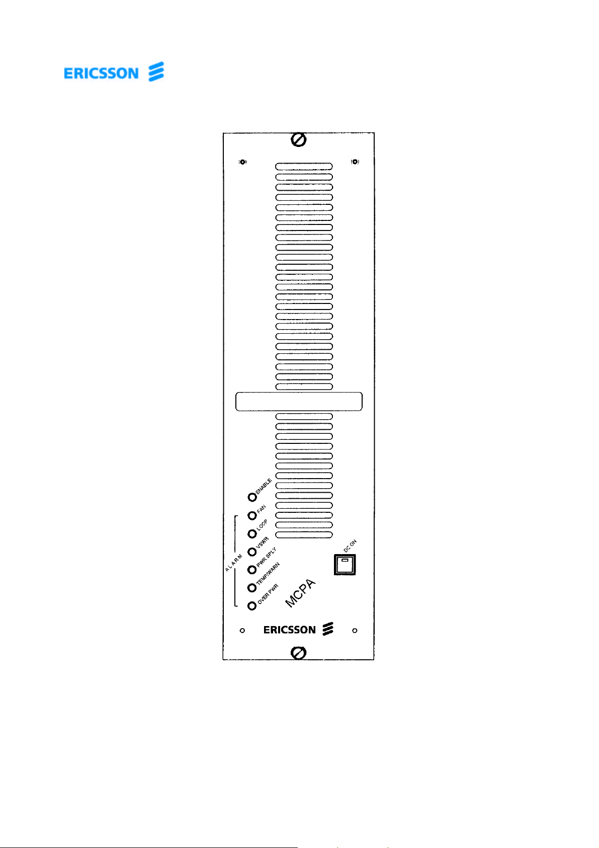
Figure 1. Ericsson Amplifier Technologies Inc.
MCPA Power Amplifier
1.4 Equipment Functional and Physical Specifications
Table 1 lists the functional and physical specifications of the MCPA power amplifier.
© 2001 – Ericsson Amplifier Technologies Inc. 2
Page 8

Table 1. Performance Characteristics
MCPA Power Amplifier
PERFORMANCE CHARACTERISTICS
Parameter Specification
Frequency 869 - 894 MHz
RF Output Power 120 Watts Average
Intermodulation Distortion -3 dBc minimum
when measured with 50 random phase sets.
Gain
69.5±0.25 dB
Modulation Format Any
Input Return Loss 14 dBr Minimum
Load Stability VSWR unconditional, all phases
Current Consumption 50 amperes nominal @ 27 VDC
DC Input Fully operational from 26 to 28 VDC
Operating Temperature
5° to 40° C
Operating Humidity 20% to 80% RH, non-condensing
Storage Humidity 20% to 95% RH, non-condensing
Dimensions 17.88” H x 5.12” D x 16.5” D
45.4 cm H x 13 cm W x 41.9 cm D
(Optional Configuration Available)
RF, DC, and I/O interface (Blind mate): 24W7 Sub-miniature connector, OSP
LED Status Monitoring Loop Alarm, VSWR Alarm, Temperature
Alarm, Power Supply Alarm, Fan Alarm,
Over Power Alarm, and DC On
1.5 Mechanical Description
The MCPA is contained in a chassis that can be mounted in a subrack enclosure. A
central heatsink is permanently mounted as part of the assembly (casting/housing).
Cooling is provided by 2 integral rear mounted fans that are easily replaced without the
need for chassis disassembly, or removal of power to the amplifier. Airflow through the
MCPA is from front through the rear of the unit.
© 2001 – Ericsson Amplifier Technologies Inc. 3
Page 9

2. INSTALLATION
2.1 Introduction
This section contains receiving, unpacking and installation recommendations for the
Ericsson Amplifier Technologies MCPA multi-carrier power amplifier. Carefully read
and review all of the information contained in this section before attempting to install or
operate the MCPA. In addition, read and review the operating instructions contained in
Section 3 before operating the equipment.
2.2 Electrical Service Recommendations
Ericsson Amplifier Technologies strongly recommends the use of AC line conditioning
and surge suppression devices at the primary AC input to the power source for the
MCPA. All electrical connections should be in accordance with the National Electric
Code, and any applicable state and local codes. In addition, lightning protection for all
systems is strongly recommended. The electric service must be well grounded.
The amplifier power source should be equipped with a separate circuit breaker,
installed in a load center with a separate mains switch or breaker. This arrangement
permits future service and maintenance of the MCPA without the necessity for
removing power to the entire site.
2.3 Receiving, Unpacking and Inspection
The MCPA has been tested and calibrated at the factory prior to shipment. No
additional readjustment is required prior to installation.
The MCPA is shipped in a single container. Check the exterior of the shipping
container for any visible signs of damage. If possible, open the container in the
presence of the delivery agent. Carefully unpack the MCPA and save all packing
material for possible reshipment. After removal from the container, check the MCPA for
physical damage such as scratched panels, damaged connectors, etc. If damage is
noted, immediately file claim with the delivery agent or freight carrier.
2.4 Repackaging for Shipment
Should it ever become necessary to re-ship the MCPA for service or repair, the
following procedure should be followed.
a. Use the original container, if possible.
b. Wrap the item in heavy paper or plastic before placing it in the shipping container.
c. Use packing material around all sides of the item.
d. Use a heavy cardboard box or a wooden container to house the item. Seal the
container with heavy-duty tape (Fiberglas) or strap the container with metal bands.
e. Mark the container: "FRAGILE - DELICATE INSTRUMENT".
© 2001 – Ericsson Amplifier Technologies Inc. 4
Page 10

2.5 Environmental Limitations
The MCPA is designed to operate in an environment as noted in Table 1 of this
manual. The MCPA must be installed in an area where an adequate and unrestricted
supply of air is available for cooling. Adequate clearance must be provided to prevent
obstruction of airflow. Confirm that proper dc power is available for the equipment.
2.6 Installation
The amplifier is produced in a Blind Mate configuration as shown in Figure 2. The
Blind Mate configuration is designed for mounting in an Ericsson Amplifier
Technologies subrack, and features a single connector on the rear panel for all RF, DC
and I/O interface connections. The following paragraphs provide installation details.
2.6.1 Recommended Tools
The following tools are recommended to assist in the installation of the amplifier.
• #1 and #2 Phillips screwdrivers
• Slotted screwdrivers, 1/8” and 1/4”
• A 5/16” or 3.5mm open-end wrench
• A multi-meter with probes
2.6.2 Blind Mate Configuration Mounting
a. Install an amplifier module into each of the mating slots of the subrack, beginning
from the left. Use firm, but not excessive force when installing the amplifiers to
ensure a good connection is made.
b. Hand tighten the retaining screws on the front panels of the amplifier modules. Do
not over tighten.
c. Ensure that an unrestricted supply of air is available at the front and rear of the
enclosure for cooling.
© 2001 – Ericsson Amplifier Technologies Inc. 5
Page 11

© 2001 – Ericsson Amplifier Technologies Inc.
Page 12

2.7 Cable Interconnections
The MCPA is produced in a Blind Mate configuration. The following paragraphs provide
interconnection details.
CAUTION
VERIFY THAT PROPER DC VOLTAGE IS AVAILABLE TO MCPA
BEFORE CONNECTIONS ARE MADE. DAMAGE TO THE MCPA
CAN OCCUR IF IMPROPER VOLTAGES ARE APPLIED.
The RF input, DC, and I/O interface is incorporated into a 24W7 Blind Mate “D” sub-miniature
connector, J1. Connections are as shown in Table 2. RF output is via an OSP Blind Mate
connector, J2.
Table 2. J1 – Blind mate 24W7 D Sub-miniature Connector
J1-Connector Pin Signal Name Description
A1 RF In PKZ26
A2, A7 No Connection No Connection
A3, A4 +DC Power In
A5, A6 DC Power Return
1-6 No Connection No Connection
7 RS-232 RXD_PS Data Out 1
8 RS-232 TXD_PS Data In 1
9 Signal Ground Ground
10 RUN/PGM PS
11 RS-232 TXD_IMD Data Out 2
12 RS-232 RXD_IMD Data In 2
13 RUN/PGM IMD
14 PA ID, GND
15-17 No Connection No Connection
© 2001 – Ericsson Amplifier Technologies Inc. 7
Page 13

2.8 Verify Connections
Recheck all connections. Make certain that all connections are correct and secure.
2.9 Verify DC Supply Voltage
Measure the DC supply voltage that will power the MCPA at the subrack terminals. The DC
supply voltage must be 27 VDC ±0.5 VDC. In addition, the power supply circuit breaker
rating must be 75 amperes minimum. Refer to Section 3 for operating instructions.
CAUTION
DO NOT OPERATE MCPA WITH A DC SUPPLY VOLTAGE
OUTSIDE OF THESE LIMITS. DAMAGE WILL OCCUR TO THE
MCPA FROM IMPROPER SUPPLY APPLICATION.
NOTE
When +27VDC is initially connected and applied to the MCPA,
all of the LED’s on the front panel except for the DC On will
illuminate momentarily.
© 2001 – Ericsson Amplifier Technologies Inc. 8
Page 14

3. OPERATING INSTRUCTIONS
3.1 Safety Precautions
During normal MCPA operation, personnel must be cognizant of the intrinsic hazards
related to electronic equipment in general, and RF power amplifiers in particular. This
amplifier subsystem generates high RF power (120 watts) which is dangerous and can
cause serious RF burns if contacted. Caution must be exercised when working with this
amplifier. While every practicable safety precaution has been incorporated into this
amplifier, the following rules must be strictly observed:
WARNING
KEEP AWAY FROM LIVE CIRCUITS
Operating personnel must observe all safety regulations
at all times. Do not make adjustments inside equipment
with hazardous voltages present. Do not operate the
amplifier without proper RF termination.
DO NOT SERVICE OR ADJUST ALONE
Under no circumstances should any person reach within
or enter any enclosure for purposes of servicing or
adjustment without the immediate presence and
assistance of another person capable of rendering aid.
Knowledge of first aid for electrical shock and burns is
necessary.
PERSONNEL
Only trained personnel are to service and adjust the
amplifier. Personnel must be trained in the maintenance
of equipment with hazardous RF power, and must be
familiar with this amplifier. In addition, the following
precautions must be observed during operation.
© 2001 – Ericsson Amplifier Technologies Inc. 9
Page 15

WARNING
MAINTAIN PROPER TERMINATION AT THE OUTPUT
PORT OF THE MCPA. DO NOT REMOVE OR EXCHANGE
RF CABLES OF THE OUTPUT LOAD CIRCUIT WHILE
THE MCPA IS IN OPERATION. DANGEROUS RF
VOLTAGE MAY EXIST AT THE FOREMOST TERMINAL
OF THE INTERRUPTED LOAD CIRCUIT DURING
OPERATION.
CAUTION
All interconnecting cables must be connected prior to
application of RF power. Although the MCPA is
designed to withstand all output load conditions
including open and short circuit conditions, it is
recommended to connect an appropriate RF load to the
output port of the MCPA prior to application of RF
power.
CAUTION
Maintain proper RF input to the MCPA. Damage to the
MCPA may occur if excessive RF input is applied.
3.2 Controls and Indicators
The MCPA is equipped with local controls and indicators on the front panel, and a rear
panel I/O interface for remote status monitoring and control. The following paragraphs
detail these features.
3.2.1 Local Controls and Indicators
Figure 3 is the front view of the MCPA. Table 3 describes the local controls and
indicators.
© 2001 – Ericsson Amplifier Technologies Inc. 10
Page 16

DC ON/OFF SWITCH
ENABLE
AND INDICATOR
SWITCH
ENABLE LED
FAN LED
LOOP LED
VSWR LED
PWR SPLY LED
TEMP/WARN LED
OVER PWR LED
Figure 3. MCPA Local Controls and Indicators
© 2001 – Ericsson Amplifier Technologies Inc. 11
Page 17

MCPA Local Controls and Indicators
CONTROL/INDICATOR FUNCTION
DC ON -
Power Supply switch and integral DC ON green LED indicator, enables
the external high power +27V power supply circuitry.
ENABLE ON -
Green LED indicates unit is ENABLED, biased on and the amplifier is
ready to amplify signals.
FAN ALARM LOOP ALARM
(Steady On)-
Yellow LED indicating a blocked or non-functioning fan.
Steady (not blinking) Red LED indicating internal control loops can no
longer minimize IMD performance. The sequence of disable and
enable commands may be used to reset the loops to their normal
conditions.
LOOP ALARM –
(Blinking On/Off, indicates
Locking Mode)
Blinking red LED indicating Locking Mode has been entered. The
locking mode is used to indicate when the module is unable to
minimize IMD performance and is attempting to adjust loop
coefficients. During this mode, IMD performance may not meet
specified values. The module will attempt to improve performance for
1 minute. If unable to improve performance during this period, the
module will indicate a loop alarm and enter the shutdown mode, and
will require power to be reset in order to clear the fault.
VSWR ALARM -
Red LED indicating load VSWR is greater than 3.0:1. Amplifier will
enter shutdown mode, and will require power to be reset in order to
clear the fault.
POWER SUPPLY ALARM -
Red LED indicating a power supply generated voltage is out of range.
Amplifier will enter shutdown mode, and will require power to be reset
in order to clear the fault.
TEMP WARNING/ALARM Dual color (Yellow/Red) LED.
TEMP WARNING: Yellow color indicates approach of excessive
operating temperature of approximately +80°C as monitored on the
heatsink. Operation of the MCPA can continue uninterrupted during
this warning condition.
Table 3.
TEMP ALARM: Red color indicates excessive operating temperature
of approximately +90°C as monitored on the heatsink. Operation of
the MCPA is disabled until the heatsink has cooled to a safe operating
temperature, at which point, operation will automatically resume.
OVERPOWER ALARM -
Red LED indicating that the RF output power from the MCPA is greater
than 2 dB above nominal output power. Amplifier will enter shutdown
mode, and will require power to be reset in order to clear the fault.
NOTE
Activation of the LOOP ALARM, VSWR ALARM, POWER SUPPLY
ALARM, TEMP ALARM or OVERPOWER ALARM will cause the
Amplifier to enter shutdown mode. The amplifier will attempt to auto
recover up to three times within 24 hours. If the alarm is still present,
the amplifier will continue to shutdown. The amplifier may also be
manually reset using the front panel button. Refer to Figure 4, which
details the ON/OFF sequence of the MCPA.
© 2001 – Ericsson Amplifier Technologies Inc. 12
Page 18

3.2.2 MCPA Power ON/OFF Sequence Summary
Figure 4 is a functional diagram of the MCPA Power ON/OFF sequence.
Initially, the MCPA +27 VDC and +15 VDC bias are both off.
After depressing the On/Off switch, both the external +27 VDC and +15 VDC bias are
on. Typical current without any RF applied to the MCPA is 18 amps.
Depressing the On/Off switch again will turn off the MCPA module completely, as it was
initially.
© 2001 – Ericsson Amplifier Technologies Inc. 13
Page 19

enabled as indicated
DC ON LED
STATUS
ENABLE LED
STATUS
INTERNAL
POWER SUPPLY
STATUS
MCPA
STATUS
OFF OFF OFF DISABLED
DEPRESS
DC ON/OFF
OPERATING
STATUS
Initial state.
MCPA is shut down.
Minimal current draw.
DC ON LED
STATUS
ENABLE LED
STATUS
INTERNAL
POWER SUPPLY
STATUS
MCPA
STATUS
OPERATING
STATUS
Module bias is
ON ON ON ENABLED
applied. MCPA is
by front panel
ENABLE LED.
Current draw
DEPRESS
DC ON/OFF
approximately 18
amps.
NOTE:
If resetting power to the MCPA does not clear the fault condition, contact Ericsson Amplifier Technologies,
or return MCPA for service.
© 2001 – Ericsson Amplifier Technologies Inc. 14
Figure 4. MCPA Power ON/OFF Sequence
Page 20

3.2.3 Remote Control/Status Interface
The MCPA is equipped with control inputs and status outputs at the I/O interface.
Section 2.7 details the interfaces for the Blind mate configurations and describes the
signals.
3.3 Initial Turn On Procedure
The following procedure is intended to verify operation of the MCPA following
installation, repair or replacement.
WARNING
EQUIPMENT OPERATORS MUST BE FAMILIAR WITH
ALL SAFETY PRECAUTIONS OUTLINED AT THE
BEGINNING OF THIS SECTION PRIOR TO OPERATING
THE MCPA. OPERATOR INJURY AND/OR EQUIPMENT
DAMAGE WILL RESULT FROM IMPROPER OPERATION.
a. Verify that all connections to the MCPA have been properly made in accordance with
Section 2 of this manual, and the outline and installation drawing, Figure 2.
NOTE
When +27VDC is initially connected and applied to the
amplifier, all of the LED’s on the front panel, except for the
DC ON, will illuminate momentarily. This is a normal
condition.
b. With no RF applied to the MCPA, press the POWER ON/OFF switch once. The DC
ON LED (part of the ON/OFF switch) will be illuminated, and the fans will be activated.
c. Observe that only the following indicators are illuminated on the MCPA front panel:
DC ON
ENABLE
d. Apply reduced RF input (-40 dBm) to the MCPA RF IN connector within the 869-894
MHz frequency range, and observe that only the DC ON and ENABLE LED indicators
remain illuminated.
© 2001 – Ericsson Amplifier Technologies Inc. 15
Page 21

CAUTION
Maintain proper RF input level within the 869-894 MHz
operating band. Improper RF input may cause severe
MCPA damage.
g. Increase input level to between -19 and -15 dBm, and observe that only the
following indicators are illuminated on the MCPA front panel.
DC ON
ENABLE
3.4 Normal Operation
The MCPA requires minimum attention during normal operation. Monitoring of the
status output provides an overall indication of MCPA health.
3.5 Shut Down Procedure
a. Reduce RF input signal level to minimum (-60 dBm).
b. Press the PWR ON/OFF switch once to disable the bias voltage and to disable +27
VDC to the internal amplifier module. The DC ON indicator will be extinguished.
WARNING
THE DC ON/OFF SWITCH DOES NOT CONTROL THE
MAIN +27 VDC FEED TO THE MCPA. IF MAINTENANCE
OR SERVICE IS TO BE PERFORMED ON THE MCPA,
DEACTIVATE PRIME DC POWER AT ITS SOURCE.
© 2001 – Ericsson Amplifier Technologies Inc. 16
Page 22

4. PRINCIPLES OF OPERATION
4.1 Introduction
This section contains a functional description of the multi-carrier power amplifier. Refer
to the block diagram of the MCPA, Figure 5, located at the end of this section.
4.2 RF Input Signal
The maximum input signal for all carrier frequencies must not exceed the limits
specified in the electrical specifications. The input VSWR should be 2:1 maximum (or
better).
4.3 RF Output Load
The load impedance should be as close as possible to 50 ohms (VSWR of 1.5:1 or
less) over the 869-894 MHz operating frequency band to ensure maximum RF power
transfer to the load.
4.4 System Functional Description
The MCPA amplifier is a multi-carrier, feed forward power amplifier, which operates
from 869 to 894 MHz with a rated output power of 120W total (average). The amplifier
employs feed forward carrier cancellation circuitry, providing extremely low
intermodulation products, equal to or less than –63 dBc. The front panel of the
amplifier contains the DC ON/OFF switch, and the status LEDs. The amplifier operates
from a 26-28 VDC input power source, and provides a rear panel input/output (I/O)
control and status interface to report all faults and alarms. Relay dry contacts are
provided for the following fault conditions:
OVERPWR – Relay dry contact closure provided for remote notification in the event
that the MCPA output is greater than 2 dB above the nominal operating power level.
The MCPA power will need to be reset in order to clear this fault condition.
MINORFLT – Relay dry contact closure provided for remote notification in the event
that the MCPA has encountered a minor fault condition, which has not caused shut
down of the amplifier, but which will require attention as soon as possible in order to
ensure uninterrupted operation. A TEMP WARNING or FAN ALARM will result in a
MINORFLT condition and remote notification. The MCPA power will need to be reset in
order to clear this fault condition.
MAJORFLT – Relay dry contact closure provided for remote notification in the event of
a potentially damaging fault condition, which has resulted in shut down of the MCPA.
Activation of the LOOP ALARM, VSWR ALARM, POWER SUPPLY ALARM, TEMP
© 2001 – Ericsson Amplifier Technologies Inc. 17
Page 23

ALARM and OVERPOWER ALARMS will result in a MAJORFLT condition and remote
notification. The MCPA power will need to be reset in order to clear this fault condition.
TTL control inputs are provided at the I/O interface. The Control and Status interface is
an 8-bit asynchronous serial bus, which complies with the EIA/TIA 232-E type Standard
for Electrical Characteristics for use in Balanced Digital Systems. The communications
protocol is as follows:
• Half Duplex
• 1 Start bit
• 1 Stop bit
• 8 Data bits
• No Parity
• 9600 bits per second (baud)
The MCPA will respond to commands, and will send a response only when commanded
first.
Although the MCPA contains no user-serviceable components (with the exception of
the fan assemblies), the following paragraphs provide operating principles, and a
general overview of its operation. Figure 5 is a functional block diagram of the MCPA.
The amplifier is comprised of the following internal functional elements:
• Carrier Cancellation
• Main/Error Driver Amplifier
• Main Amplifier
• Error Amplifier
• DC/DC Function
• Microprocessor Control
• Loop Processor
• Pre-distorter
The main amplifier employs class AB amplification for maximum efficiency and low
intermodulation distortion. The error amplifier and main/error driver amplifiers operate
class A mode. The input RF signal is amplified by the carrier cancellation circuit, and
then split into a signal and a reference path. The signal path is sent through the main
driver amplifier, where the amplitude and phase are modified, based on the reference
signal, and then amplified by the main amplifier. The signal is coupled to the carrier
cancellation circuit where the 180° phase shifted and amplified signal meets the
reference signal. At this point the combined signal, which has a canceled carrier
(called the IMD signal), is sent to the IMD leg of the feed forward amplifier.
© 2001 – Ericsson Amplifier Technologies Inc. 18
Page 24

The IMD signal is sent to the error driver amplifier and error amplifier. Signal amplitude
and phase are adjusted from the input by the loop processor. The signal is re-injected
into the main amplifier output signal, and the combined signal yields suppression of
intermodulation products of -65 dBc minimum.
The following paragraphs describe each of the functional elements of the MCPA.
4.4.1 Main Amplifier
The main amplifier operates class AB, and provides approximately 29.5 dB of gain over
the operating frequency band of 869-894 MHz. It operates from 27 VDC and utilizes 15
VDC to derive bias. The main amplifier is directly mounted to the heatsink. Within the
main amplifier are temperature sensors, which detect the baseplate (heatsink)
temperature. In the event that the heatsink temperature reaches approximately +80°C,
the TEMP WARNING (yellow) LED will be illuminated. Operation of the MCPA may
continue during this condition. In addition, should the heatsink temperature further rise
to approximately +90°C, bias to the internal amplifier is shut down to prevent damage
during the over temperature condition. The TEMP ALARM (red) LED will be
illuminated. Operation of the MCPA is inhibited until the heatsink temperature has
returned to a safe operating level. The fault condition will automatically self-clear when
the heatsink has cooled to a safe level, and normal operation will again be restored.
The cause of any TEMP WARNING or TEMP ALARM condition should be investigated
as soon as possible to ensure continuous uninterrupted MCPA operation.
4.4.2 Error Amplifier
The main function of the error amplifier is to amplify the distortion products generated
by the main amplifier. These distortion products are amplified and precisely phase
shifted (180° with those at the output), such that when they are combined with the main
signal at the output of the amplifier, the result is cancellation of the distortion products.
The error amplifier operates class A, has 57 dB of gain, and produces 2 watts of output.
The amplifier operates from 27 VDC, and utilizes 15 VDC to derive bias. The error
amplifier is mounted to the heatsink, and utilizes an output circulator to protect the error
amplifier output. The load port of the circulator is connected to a detector to monitor
reflected power. The resulting analog voltage is monitored by the microprocessor to
prevent operation and damage to the MCPA in the event of excessive load VSWR. In
the event of a load VSWR of greater than 3.0:1, the microprocessor will cause the
MCPA to go into a VSWR FAULT mode, and remove bias to the internal amplifier for
protection. Illumination of the front panel VSWR alarm indicator confirms this
condition. The fault condition may be reset by re-setting power to the MCPA. Refer to
Figure 4 for sequence.
4.4.3 Amplitude and Phase Adjustment
The two loops are controlled via the microprocessor through the main and error driver
amplifiers. The amplifiers include vector control circuitry to adjust amplitude and phase
© 2001 – Ericsson Amplifier Technologies Inc. 19
Page 25

of the RF signals. The microprocessor controls the amplitude and phase adjustments
of the two loops. The loop processor responds to the amplitude and phase of the IMD
loops. In the event of a failure of the loops or processor, the front panel LOOP alarm
indicator will be illuminated, and further operation of the MCPA will be inhibited. The
fault condition may be reset by re-setting power to the MCPA. Refer to Figure 4 for
sequence.
4.4.4 Amplifier Module Cooling
The amplifier is cooled via forced air through the heatsink. Two rear fans are used to
draw air through the heatsink. The fans are field replaceable and are monitored for fan
faults. In the event of a fan failure, the front panel FAN alarm indicator will be
illuminated. Operation of the MCPA will continue, however, at some point, the TEMP
WARN/ALARM circuitry may be activated due to reduced cooling, and may inhibit
MCPA operation (refer to paragraph 4.4.1). The fan(s) are externally mounted and are
easily replaced without removal of any of the MCPA covers, and without the need to
shut down the MCPA. Refer to Maintenance section 5.4 for fan assembly replacement
and ordering instructions.
4.5 Power Distribution
The amplifier employs a DC/DC converter to regulate the amplifier sub-circuits to the
required voltage, based on a 26-28 VDC input. The power supply board converts the
input voltage to +/-5V, and +/-15V used by the loop processor and microprocessor.
Internal monitoring circuitry monitors the supply voltages, and activates the front panel
POWER SUPPLY alarm LED indicator in the event of a fault. Operation of the MCPA
is inhibited following detection of this fault . The fault condition may be reset by resetting power to the MCPA. Refer to Figure 4 for sequence.
4.6 Intermodulation Distortion Performance
The MCPA amplifier is designed to deliver a 120W average power, multicarrier signal,
with extremely low intermodulation products, over the passband of 869-894 MHz.
4.6.1 Intermodulation Distortion
When measured with fifty (50) random phase sets, intermodulation products are
below -63 dBc.
4.7 Description of Operating Modes
4.7.1 Default mode
When initially powered up (or installed into the shelf), the MCPA amplifier defaults to
the standby mode after a brief initialization sequence is completed. During the
initialization sequence, the LEDs on the front panel will briefly illuminate.
© 2001 – Ericsson Amplifier Technologies Inc. 20
Page 26

4.7.2 Standby Mode:
(All LEDs off)
The MCPA has not had the DC power switch pressed and is not biased on. Low level
communication ( e.g. between the subrack and amplifier) is enabled.
4.7.3 DC On Mode
(DC Switch LED – ON)
The front panel DC on switch has been depressed, and the integral LED indicator is
illuminated. When used with the Ericsson Amplifier Technologies subrack, the subrack
acknowledges the initial operation of the module and configures the subrack to insert
the module into the combining circuit, provided the module does not indicate an alarm
which would shutdown the module. Thus the module system will reconfigure itself
automatically as the additional modules are (DC) powered-up, to effectively use the
new module.
4.7.4 Enable Mode
(DC Switch and Enable LED – ON)
The MCPA is amplifying the signal. (When used with Ericsson Amplifier Technologies
subrack, all power is being combined.)
4.7.5 Shutdown Mode
Any of these LEDs ON: VSWR, OVER PWR, TEMP/WARN, LOOP or PWR SPLY
The MCPA amplifier has turned itself off for protection. All alarm indications are
latched, and the amplifier is shutdown. The amplifier can be reset by pressing the DC
switch. If the alarm still exists, the amplifier will re-enter the shutdown mode.
4.7.6 ALC Mode
(Blinking OVER PWR LED)
The module supports power limiting to mitigate an overdrive condition. When the
OVER PWR LED blinks, the module has entered the ALC mode. In the ALC mode, the
module limits the maximum transmit power to 0.5 dB above nominal output power by
reducing the gain of the MCPA. The gain of the MCPA is continuously adjusted to
maintain this limited value. If the loop circuits can no longer maintain the limited value
due to excessive input power, the MCPA will protected itself by shutting down and
indicate a overdrive condition with a steady OVER PWR LED indication. After 30
seconds, the MCPA will turn back on in the minimum gain setting, and attempt to limit
power once again.
If the power is still too high during the subsequent attempt, the module will overdrive
again and shutdown. The re-enable sequence will be performed three times before the
module remains shutdown, and will require re-initialization (power up sequence) in
order to reset.
© 2001 – Ericsson Amplifier Technologies Inc. 21
Page 27

If the output power is below the limited value during a subsequent attempt, the gain of
the module will be increased until either the limited value is reached, or nominal gain is
restored.
4.7.7 Locking Mode
(Blinking LOOP LED)
The locking mode is used to indicate that the module is unable to minimize IMD
performance, and is attempting to adjust loop coefficients. During this mode IMD
performance may not meet specified values. The module will attempt to improve
performance for 1 minute. If unable to improve performance during this period, the
module will indicate a loop alarm and enter the shutdown mode.
4.8 Description of Alarm Conditions
The amplifier reports various alarms, indicated via a front panel LED, and via the I/O
connector on the rear. The following paragraphs detail the alarm conditions, and
expected operation during each. Refer also to Table 3 for a description of the alarm
indications.
NOTE
Activation of the LOOP ALARM, VSWR ALARM, POWER
SUPPLY ALARM, TEMP ALARM or OVERPOWER ALARM
will cause the MCPA to shut down. The fault condition may
be reset by re-setting power to the MCPA. Refer to Figure 4
for sequence.
4.8.1 LOOP Alarm
Indicates control loops can no longer minimize IMD performance. The sequence of
disable and enable commands may be used to reset the loops to their nominal setting.
4.8.2 VSWR Alarm
When the reverse power is more than 30 Watts for 5 seconds a VSWR is given.
4.8.3 TEMP/WARN Alarm
Two levels of temperature warnings are provided via the dual color TEMP/WARN LED.
A yellow TEMP/WARN LED indicates module heatsink temperature has risen to a high
level, approximately 80 degrees C. . Normal operation can continue, provided the
temperature remains below the 90 degree C TEMP/WARN shutdown level. At
approximately 90 degrees C, the TEMP/WARN indicator will switch to a red color,
© 2001 – Ericsson Amplifier Technologies Inc. 22
Page 28

indicating the excessive module heat sink temperature. The module will enter the
shutdown mode. After sufficient cooling has occurred, and the fault no longer exists,
the module will automatically re-enable itself.
4.8.4 PWR SPLY Alarm
This LED indicates a fault in a power supply generated voltage. The module will enter
the shutdown mode, requiring re-initialization (power up sequence) in order to reset the
fault condition.
4.8.5 FAN Alarm
This LED indicates that a fan is not operating or has been removed.
4.8.6 OVER PWR Alarm
This LED indicates that output power from the amplifier is above 52.8 dBm. The
amplifier will enter the shutdown mode, requiring re-initialization (power up sequence)
in order to reset the fault condition.
© 2001 – Ericsson Amplifier Technologies Inc. 23
Page 29

© 2001 – Ericsson Amplifier Technologies Inc.
Page 30

5. MAINTENANCE
5.1 Introduction
This section provides information for periodic maintenance of the MCPA, as well as
tests which are recommended in order to evaluate performance of the amplifier. Refer
to paragraph 5.3 for troubleshooting procedures for the MCPA.
CAUTION
Do not attempt to repair the MCPA. The amplifier
contains no user-serviceable components, with the
exception of the fan assemblies. Further damage will
result from improper repairs.
NOTE
Do not break the seals on the equipment, as this will void
the warranty.
5.2 Periodic Maintenance
Periodic maintenance tasks and recommended intervals are listed in Table 4.
Table 4. Periodic Maintenance Tasks
CATEGORY TASK RECOMMENDED
MAINTENANCE ACTION
INTERVAL
Cleaning
Inspection
Fans, Air
Inlets/Outlets
Cables and
Connectors
30 Days Inspect and clean in accordance
with paragraph 5.2.1.
12 Months Inspect all cables for any signs of
damage or wear. Check and
verify that all connections are
secure.
Performance
Tests
12 Months Perform tests as outlined in
paragraph 5.2.3.
© 2001 – Ericsson Amplifier Technologies Inc. 25
Page 31

5.2.1 Cleaning Air Inlets/Outlets
The air inlets and outlets are located at the front and rear of the unit. Air is drawn in
from the front, and exhausted through the fans at the rear of the MCPA. These areas
should be cleaned at 30 day intervals, or sooner, if the equipment is operated in a
severe dust environment. Use dry, low-pressure compressed air, or a brush with soft
bristles to loosen, remove and clean off any accumulated dust from the fans and the air
inlet and outlet areas.
5.2.2 Test Equipment Required
Table 5 lists the test equipment required for evaluating MCPA performance. Suitable
equivalents may be substituted.
Table 5. Test Equipment Required
NOMENCLATURE QTY MANUFACTURER MODEL
Signal Generator 1 H/P ESG
Attenuator, 40 dB, 250 Watt 1 Weinschel S3-40-43
Attenuator, 20 dB, 20 Watt 2 Weinschel AT20
Spectrum Analyzer 1 H/P 8560E
Directional Coupler, 30 dB 1 RF Power DDC-901-931-R5-30
Power Meter/Sensor 1 H/P 437B/8481A
Power Supply 1 H/P 6673A
5.2.3 Performance Tests
Performance tests should be performed at 12-month intervals, or as directed by the
resident maintenance authority, to ensure that the MCPA is functioning properly and
within expected specification limits.
© 2001 – Ericsson Amplifier Technologies Inc. 26
Page 32

5.3 Troubleshooting Procedures
Figure 6 is the troubleshooting flow chart for the MCPA.
CAUTION
Do not attempt to repair the MCPA. The amplifier
contains no user-serviceable components, with the
exception of the fan assemblies. Further damage will
result from improper repairs.
NOTE
Do not break the seals on the equipment, as this will void
the warranty.
5.4 Fan Assembly Replacement Procedure
The fan assemblies are mounted to the rear of the MCPA. Replacement is
accomplished by unlocking the 2 quick disconnects, which secure the fan to the rear
panel. Disconnect fan wiring harness connector. Reconnect the fan wiring harness
connector to the replacement fan. Mount replacement fan to rear panel by inserting the
tabs and locking the 2 quick disconnects on the fan assembly to the rear panel of the
amplifier chassis.
Replacement fan assemblies (part number BKV 106 59/1) can be ordered directly from
Ericsson Amplifier Technologies.
© 2001 – Ericsson Amplifier Technologies Inc. 27
Page 33

(Sheet 1 of 2)
BEGIN HERE
Is the
DC ON LED
illuminated?
Yes
Is the
ENABLE LED
illuminated?
Yes
Is the
FAN ALARM LED
illuminated?
Is the POWER
No
switch/circuit breaker
Yes
tripped or OFF?
No
No
Is there air
Yes Yes
flow through both fans
of the MCPA?
Reset switch/breaker by
pushing switch firmly down, then
release. If breaker trips again,
contact Ericsson Amplifier
Technologies for assistance, or
return MCPA for service.
Verify connections and
DC power to MCPA. If secure,
contact Ericsson Amplifier
Technologies for assistance, or
return MCPA for service.
Refer to Figure 5.
Reset MCPA.
If unable to achieve ENABLE mode,
contact Ericsson Amplifier
Technologies for assistance, or
return MCPA for service.
Attempt to reset
fault circuits by resetting power
to the MCPA as shown in Figure 5.
If fault returns, contact Ericsson
Amplifier Technologies for
assistance, or return MCPA
for service.
Remove obstruction, or replace
No
No
fan. Remove 4 screws which secure
it to the rear panel. Disconnect fan
harness connector. Install new
fan in reverse order.
Attempt to reset fault circuits
Is the
LOOP ALARM LED
illuminated?
Yes
by resetting power to the MCPA
as shown in Figure 5. If fault returns,
contact Ericsson Amplifier
Technologies for assistance,
or return MCPA for service.
No
Continue to sheet 2
Figure 8. MCPA Troubleshooting Flow Chart
© 2001 – Ericsson Amplifier Technologies Inc. 28
Page 34

(Sheet 2 of 2)
From sheet 1
Yes
Is the
VSWR ALARM LED
illuminated?
No
Yes
Is RF output
connection secure, and
connected to a suitable
load (or antenna)?
Attempt to reset fault circuits
by resetting power to the MCPA as
Yes
shown in Figure 5. If fault returns,
contact Ericsson Amplifier
Technologies for assistance, or
return MCPA for service.
POWER OFF!
No
Restore RF output connection,
and/or repair antenna, antenna
connection.
Is the
POWER SUPPLY
ALARM LED
illuminated?
No
Is the
TEMP ALARM LED
illuminated?
No
Is the
OVER PWR
ALARM LED
illuminated?
Yes
flow through the front
of the MCPA?
Reduce RF
input signal level
and verify that output
Is there air
Yes
power measurement
is < maximum rated power.
Does the OVER PWR
Yes
ALARM
remain?
Verify connections to MCPA.
If secure, contact Ericsson Amplifier
Technologies for assistance, or
to MPD for service.
return MCPA for service.
Attempt to reset fault circuits
by powering MCPA OFF/ON, and
then apply ENABLE command. If fault
Yes
returns, contact Ericsson Amplifier
Technologies for assistance,
or return MCPA for service.
Replace fan. Remove 4 screws
No
which secure it to the rear panel.
Disconnect fan harness connector.
Install new fan in reverse order.
Attempt to reset fault circuits
by resetting power to the MCPA as
shown in Figure 5. If fault returns,
Yes
contact Ericsson Amplifier
Technologies for assistance,
or return MCPA for service.
No
Ensure ambient temperature
Is the
TEMP WARN
No
ALARM LED
Yes
illuminated?
is < 50° C. Attempt to reset fault
circuits by resetting power to the MCPA
as shown in Figure 5. If fault returns,
contact Ericsson Amplifier
Technologies for assistance,
or return MCPA for service.
If problem remains or is not
No
listed, contact Ericsson Amplifier
Technologies for assistance,
or return MCPA for service.
Figure 8. MCPA Troubleshooting Flow Chart
© 2001 – Ericsson Amplifier Technologies Inc. 29
 Loading...