

Page 1
60 GOUGH ROAD, MARKHAM, ONTARIO L3R 8X7
Tel: (905) 940-1400 Toll Free: 888-86KAVAL Fax: (905) 946-3392
http://www.kaval.com
USER MANUAL FOR
BI-DIRECTIONAL AMPLIFIERS
800 & 900 MHz
MODEL BDA-1000
DCM000000001
Revision 1, May 27, 1999
l Page 1 Kaval Telecom Inc. DCM000000001
Page 2

TABLE OF CONTENTS
• FCC NOTICE 3
• INTRODUCTION 4
• BLOCK DIAGRAM 5
• TECHNICAL SPECIFICATIONS 6
• MULTIPLE CHANNEL AMPLIFICATION POWER DE-RATING REQUIREMENTS 7
• BOOSTER AUTOMATIC GAIN CONTROL (AGC) FUNCTIONAL DESCRIPTION 7
• BDA CONTROLLER OPERATION 8
• BDA Controller User Interface 9
• LED and Audible Indicators: 9
• Controls: 9
• Status Displays 10
• Current Monitor Status 10
• Thermal Monitor Status 10
• AGC Status 10
• Master Status 10
• Menus 11
• Main Menu 11
• Gain Menu 12
• Uplink & Downlink Booster Menus 12
• Uplink and Downlink PA Menus 13
• AGC Menu 13
• Temperature Menu 13
• Fan Select 13
• Battery 14
• Controller Menu 14
• Calibration Menu 14
• INSTALLATION 15
• FIELD ADJUSTMENTS 15
• TROUBLESHOOTING 16
• Maintenance & Safety 16
• Maintenance Philosophy 16
• Troubleshooting Procedure 16
l Page 2 Kaval Telecom Inc. DCM000000001
Page 3

• FCC NOTICE
l Page 3 Kaval Telecom Inc. DCM000000001
Page 4
• INTRODUCTION
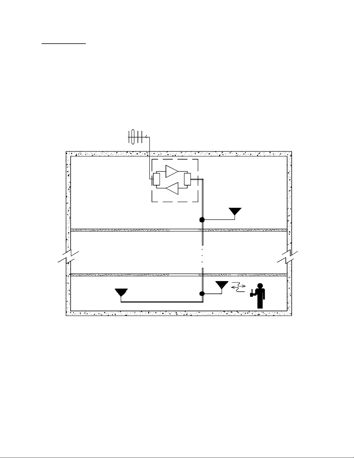
This Operator’s Manual covers the use, operation and installation of the BDA-1000 800 & 900 MHz Bi-Directional Amplifiers
(BDA’s). BDA’s are intended to extend radio frequency coverage into areas with coverage deficiency such as inside office
buildings, shopping malls, hospitals, tunnels etc. They are designed to be located independent of the Donor Transceiver Site and
are equipped with their own antenna systems - one to communicate with the Donor Transceiver Site and the other(s) to
communicate with radio equipment in the area with coverage deficiency.
For proper BDA System operation with no feedback problems, the RF isolation between the roof top antenna and the indoor
antenna(s) must exceed the net system gain by at least 12 dB. Note that the net system gain takes into account the BDA gain,
antenna gain, cable & connectors losses.
ROOF TOP ANTENNA
FROM / DONOR
TRANSCEIVER
N
KAVAL
BDA
D
D
SIGNAL
TAP
SIGNAL
TAP
COAX
CABLE
F2
F1
N-1
B
l Page 4 Kaval Telecom Inc. DCM000000001
Page 5
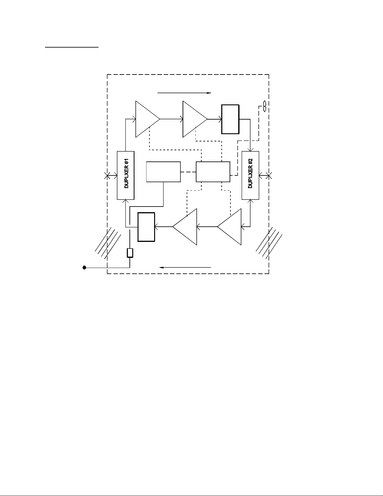
• BLOCK DIAGRAM
DOWNLINK DIRECTION
ROOF TOP
ANTENNA
VENTILATION
AC POWER
INPUT
BOOSTER #1
HP
LP
28V POWER
SUPPLY
REJECT FILTER #2
TERMINAL BLOCK
UPLINK DIRECTION
PA #1
PA #2
REJECT FILTER #1
BDA
CONTROLLER
BOOSTER #2
COOLING FANS
HP
IN BUILDING
ANTENNA
LP
VENTILATION
Power and Control Connections ------RF Connections ____
BDA Controller : An enclosed unit with microcontroller, LED indicators, buttons, and two-line display.
Temp Sense & Cooling Fans : Controlled by the BDA Controller to ensure safe and reliable operation.
28V Power Supply : Providing all DC Power, with optional Gell-Cell Battery Backup.
Duplexers : Isolating Downlink and Uplink Frequencies, and coupling to antennas.
Reject Filters : Installed if required to eliminate feedback.
Boosters : High Gain (11 to 65 dB) Linear Amplifiers supplying up to 1 Watt of RF Power. The
basic gain is adjustable via the BDA Controller over a 33 to 65 dB range, and an
Automatic Gain Control (AGC) provides an additional 23 dB range.
PA Power Amplifiers : Optional Linear Power Amplifiers providing 15 dB of additional gain, and up to 20 Watts
of RF Power.
l Page 5 Kaval Telecom Inc. DCM000000001
Page 6

• TECHNICAL SPECIFICATIONS
The BDA provides for both directions a nominal 65dB gain Booster and a 15dB gain Power Amplifier (PA). The linear Booster has
a high gain range of 11 to 65 dB supplying up to 1 Watt of RF Power. The basic gain is adjustable via the BDA Controller over a 31
dB range, and an Automatic Gain Control (AGC) provides an additional 23 dB range. The isolation between the uplink and downlink paths is provided by two high performance bandpass Duplexers.
RF Performance Downlink Uplink
1 dB Compression Point +27 dBm with Booster only
3rd Order Intercept Point IP3 +37 dBm with Booster only
BDA Controller
Electrical
Mechanical
Frequency Range As per Band requirements and Duplexer:
Trunking: 851-869 MHz
Cellular: 869-891.5 MHz
Cellular: 880-894 MHz
Trunking: 935-941 MHz
Please consult Kaval for other 800-960
MHz band options.
Nominal Max. Gain 65 dB with Booster only
80 dB with Booster & PA
Gain Adjustment 31dB (in 1dB steps)
+40 dBm with Booster & PA
+50dBm with Booster & PA
Impedance 50 ohms Nominal
VSWR 1.5:1 Max
Features Microprocessor Controller
Current Monitoring for 2 Boosters, 2 PA’s, 2 Fans
Full Gain Control
Battery Backup Control & Charging
Primary AC Power Switchmode Universal 120/230V AC +/- 10%, 50-60Hz
Total DC Current Drain Nominal 2 to 6 Amps @ 28 VDC
BDA Controller 300 ma @ 28 VDC
1W Boosters 650 ma @ 28 VDC
Fault thresholds Typically 200 ma and 900 ma
20 Watt PA’s 1.5A @ 28 VDC
Fault thresholds Typically 160 ma and 1.8 A
Batteries Two 12 VDC Sealed Lead -Acid Batteries, 10-100 AH
Battery Backup Time: Boosters only, 20 AH - 8 hrs Typical
Battery Backup Time: Boosters & PA’s, 100 AH - 8 hrs Typical
Charge Time: 10 AH - Approx. 6 hrs, 100 AH - Approx. 48 hrs. Typical
Charge Current from BDA Controller is 3 Amps Maximum
The BDA will shut down for Battery Voltages below 21 VDC.
Dimensions W x H x D 20” x 24”x12”
Weight 100 lbs. approx.
Housing Rugged Nema-Style Cabinet - Wall Mountable
Connectors N female
As per Band requirements and Duplexer:
Trunking: 806-824 MHz
Cellular: 824-846.5 MHz
Cellular: 835-849 MHz
Trunking: 896-902 MHz
Please consult Kaval for other 800-960
MHz band options.
l Page 6 Kaval Telecom Inc. DCM000000001
Page 7

• MULTIPLE CHANNEL AMPLIFICATION POWER DE-RATING REQUIREMENTS
BDA’s will amplify all signals that fall within their Pass-Band range. The output power will be “shared” between all channels being
amplified. Another multiple channel effect is Intermodulation - off-channel signals produced from non-linear effects between the
intended channel signals. These may cause interference to receiving equipment.
In order to minimize Intermodulation off-channel signals, Power De-rating must be applied. In the USA there are FCC
Intermodulation Specifications published in the EIA Standard PN2009. The Tables below give the maximum per channel Output
Levels allowed as a function of the number of channel.
Note that depending on the actual amplifier input levels, the gain of the BDA may need to be reduced to comply with the above
regulations.
Number of Channels Maximum Output Power per Single Channel for Uplink or Downlink
Using both a Booster and PA
1 +40.0 dBm
2 +28.7 dBm
4 +24.0 dBm
6 +21.3 dBm
8 +19.5 dBm
10 +18.1 dBm
Number of Channels Maximum Output Power per Single Channel for Uplink or Downlink
Using only a Booster
1 +27.0 dBm
2 +20.1 dBm
4 +15.4 dBm
6 +12.7 dBm
8 +10.8 dBm
10 +9.4 dBm
Note: Above levels are established with AGC disabled. De-ratings are based on values calculated using EIA standard
PN2009. Actual Amplifier performance may exceed the above criteria.
• BOOSTER AUTOMATIC GAIN CONTROL (AGC) FUNCTIONAL DESCRIPTION
Both Downlink and Uplink paths, with Boosters only, or with Boosters and PA’s, are equipped with AGC. The Booster based AGC
has a dynamic attenuation range that maintains a factory set composite output nominal power of +23.2 dBm at the Booster output.
The AGC gain varies dynamically to maintain this level and limits strong signal levels that could cause more Intermodulation. The
AGC starts to turn on at +23.2 dBm, therefore, at a gain setting of 70 dB, the AGC will start to turn on at +23.2 – 70 = -46.8 dBm
input level, and would maintain the +23.2 dBm output at an input levels higher than –46.8 dBm. Below the AGC turn-on threshold,
the output level will decrease linearly with the input signal. With a PA installed in the path, the AGC maximum output level is 15 dB
higher.
l Page 7 Kaval Telecom Inc. DCM000000001
Page 8
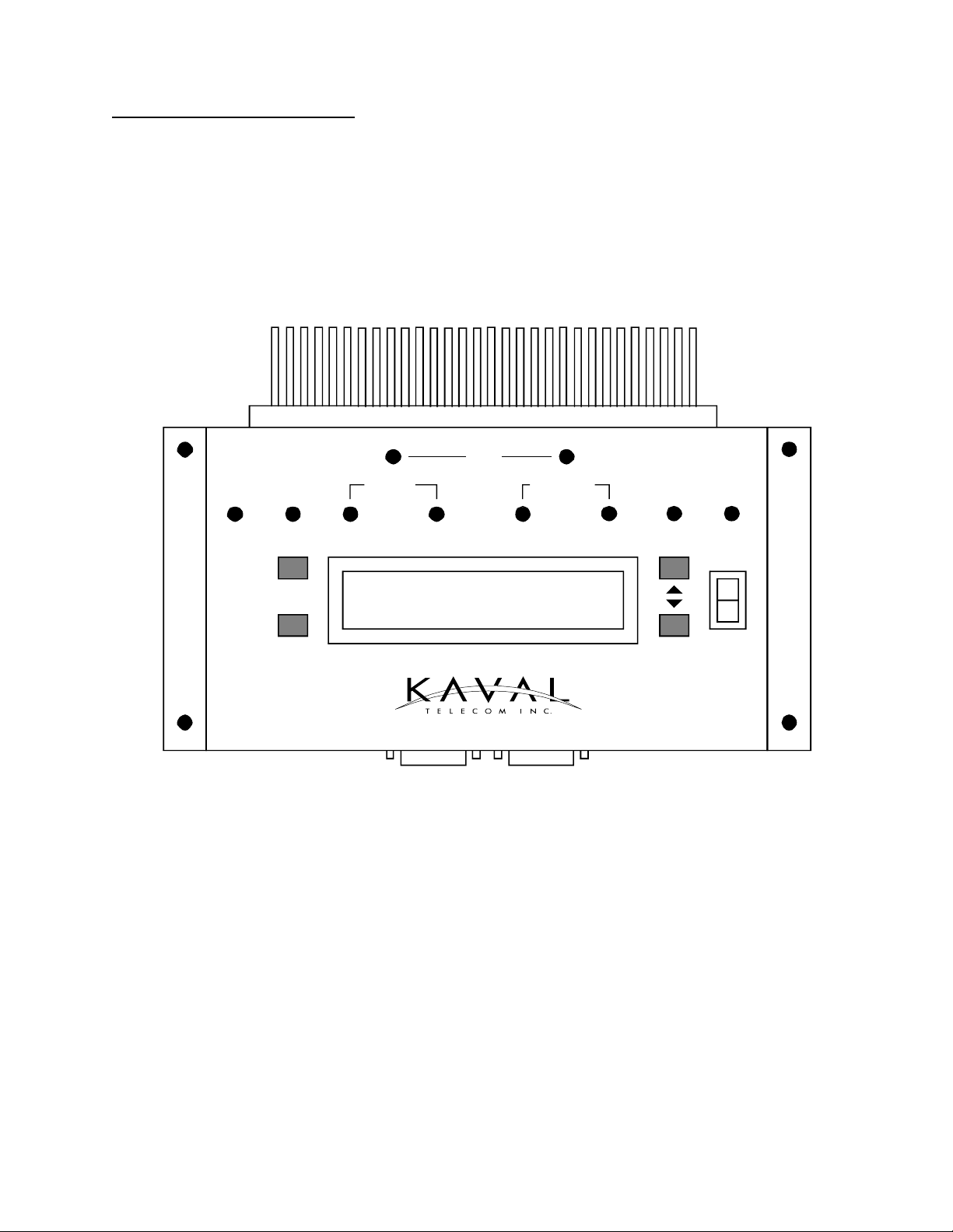
• BDA CONTROLLER OPERATION
The BDA Controller is a microprocessor based part of a Kaval BDA that provides all control, fault monitoring, and settings for the
BDA. It interfaces to the 28 VDC Power Supply, the optional 24 VDC Battery (both monitoring, transferring, and charging), control
signals to the Boosters, and provides monitored DC power for the Boosters and PA’s. Overall dimensions of the case are 9”
(including flanges) x 3.5” x 1.25”. The heatsink extends about 1.75 inches above the case and is 4 inches wide.
AGC
DOWNLINKUPLINK
PWR FAIL TEMP FAN
BDA CONTROLLER
BATT
BATT BOOST
SELECT
BDA OK
PA
BOOST PA
ADJUST
ON
OFF
POWEREXIT
The BDA Controller display is a 2 line by 20 character Vacuum Fluorescent (VFD) display. The connectors are all secure lock
types and should only be plugged and unplugged by a service technician.
l Page 8 Kaval Telecom Inc. DCM000000001
Page 9

• BDA Controller User Interface
• LED and Audible Indicators:
PWR FAIL Lights if primary power fails, and the system is on Battery Backup.
BATT Lights when the Battery (if installed) voltage drops below 24 VDC which roughly indicates 50% of backup
capacity remaining. This may occur as a result of normal discharge in a backup situation, Battery
exceeding its useful life, or a Battery failure such as water loss or shorted cell.
In addition, while running on Battery Backup, If the Battery drops below 22 VDC, the LED will begin to blink
indicating that self-shutdown is imminent. If the Battery drops below 21 VDC the BDA will shut down
completely to protect the Battery from damaging deep discharge.
UPLINK BOOST Lights if the Uplink Booster is enabled and has an overcurrent, undercurrent, or internal fault.
UPLINK PA Lights if the Uplink PA (Power Amplifier) is enabled and has an overcurrent, undercurrent, or internal fault .
DNLINK BOOST Lights if the Downlink Booster is enabled and has an overcurrent, undercurrent, or internal fault.
DNLINK PA Lights if the Downlink PA is enabled and has an overcurrent, undercurrent, or internal fault .
UPLINK AGC Lights to indicate that an Input Signal of sufficient strength is present to cause the AGC circuit (if enabled)
to act to reduce gain. The level at which AGC action occurs is not a fixed signal level. It depends upon the
user setting for output level target. When lower targets are set, the AGC will begin to act at lower input
levels. When AGC is disabled, the LED does nothing. If the Input Signal exceeds the AGC ability to reduce
gain, an overload condition exists, and the AGC LED blinks rapidly.
DNLINK AGC Operates the same as the Uplink AGC LED, but for the Downlink.
TEMP Lights when the BDA system temperature, as detected by a digital sensor in the fault monitor, exceeds the
user programmed high temperature threshold.
FAN Lights when the Cooling Fan(s) (if enabled) have an overcurrent or undercurrent condition.
BUZZER The Buzzer sounds briefly during button presses for audible feedback. Where a User Function requires a
confirmation, a short beep is emitted. During a Fault Condition, a long periodic beep is sounded (this can
be disabled). When the Battery is about to be depleted when on Battery Backup Power, the Buzzer will
sound continuously.
• Controls:
ON/OFF Power Switch for turning the BDA operation on and off. Note that this only controls the BDA Controller,
Boosters, PA’s, and Fans; the DC Power Supply is still operating.
SELECT This Button is used to enter the Main Function Menu and Submenus, and where applicable to confirm a
Function selection chosen with the Adjust Buttons.
EXIT This Button is used to cancel any Function changes, reverting to previous settings. If a Fault has occurred
and its Status is displayed, pressing the Exit Button clears the fault.
ADJUST These buttons Scroll up and down between Status, Function, and Menu display items. They also adjust
programmable numeric values up and down.
l Page 9 Kaval Telecom Inc. DCM000000001
Page 10

• Status Displays
The BDA Controller’s Display normally shows one of 4 Status Displays. Pressing the Adjust Buttons sequences
through the 4. Pressing the Select Button from any status screen enters the Main Menu. Pressing the Exit Button
does nothing, except when a Fault condition exists and Exit Button clears the fault. If a Fault occurs, the display
switches to the Master Status display and shows a text message for the Fault(s).
• Current Monitor Status
This Screen displays the current drawn by each Booster and PA in the system. The top row shows abbreviated
names for the amplifiers, the bottom row shows the current being drawn by each module. Entries for modules
disabled by another module’s fault show “Dsbl”. Entries for modules that are manually disabled are blank. Modules
that have a fault have their current indication blinking. If an overcurrent has occurred, then the word “Over” appears
instead of a number.
Up-B Up-P Dn-B Dn-P
0.65 Over 0.60 2.35
• Thermal Monitor Status
This Screen shows current temperature fan and battery status. Temperature readout is in degrees Celsius. If an
over-temperature condition exists, temperature will flash. Each fan has an indication of On, Off or Fail. Battery
voltage is displayed in volts to a resolution of 10 mV. If battery is not installed, display says “None” Battery voltage
flashes if it is low.
Temp FanA FanB Batt
53C ON Fail 26.25
• AGC Status
This Screen displays data about AGC operation and current gain setting. If AGC is disabled, then the readout for that
direction shows “Off” (*). If AGC is enabled, but input signal is below minimum input level for AGC action, readout
shows “Ok”. If AGC is enabled, and AGC is acting, then readout shows equivalent single carrier input level for that
direction in dBm. (*) If AGC is enabled, and amplifier is overdriven, readout shows blinking “Over” (*).
GN-UP-AGC GN-DN-AGC
65dB Dsbl 78dB 23dB
• Master Status
This Screen shows normally ;
BDA OK
If a Fault occurs, then a display such as ;
Fault!
Overtemperature
Will be shown.
l Page 10 Kaval Telecom Inc. DCM000000001
Page 11

Fault Displays include ;
Up Boost Overcurrent Up PA Overcurrent
Dn Boost Overcurrent Dn PA Overcurrent
Up Boost Undercurr. Up PA Undercurrent
Dn Boost Undercurr. Dn PA Undercurr
Fan A Fail Fan B Fail
Battery Low Imminent Shutdown
Primary Power Fail Overtemperature
Up Boost Internal Up PA Internal
Dn Boost Internal Dn PA Internal
External Fault Controller Fault
Calibration Fail Up Boost EEPROM
Dn Boost EEPROM Uplink Overdrive
Downlink Overdrive RS-232 Active
• Menus
• Main Menu
The Main Menu is entered by pressing the Select Button from any Status Display. If the Password is set to anything
but 000 (default), then a Password Entry Screen appears. The user uses the Adjust Buttons to select a digit, and
presses the Select Button to enter that digit. The cursor moves to the next digit and enters it. When the third digit is
entered, and the Password is correct, the Main Menu becomes available. If an incorrect Password is entered, then the
message “Wrong Password” appears for a few seconds and the user must start again. If the Password is set to 000
(disabled) the Main Menu is available immediately.
Enter Password
4**
Main Menu entries are used to group Functions by category. The User selects the Category and a Sub-Menu appears
listing available Functions. While in the Main Menu, the top row of the display shows “Main Menu”, and the bottom row
shows the Sub-Menu headings as one scrolls through them. When a Sub-Menu is selected, the Sub-Menu heading
replaces the Main Menu heading in the top row, and the bottom row then shows the Sub-Menu entries. If no Buttons
are pressed for 5 minutes while in any Menu the Display reverts to the last Status Display.
Available main Menu entries are:
Gain Uplink Booster
Uplink PA Downlink Booster
Downlink PA Temperature
Fans Battery
Controller Calibration
l Page 11 Kaval Telecom Inc. DCM000000001
Page 12

• Gain Menu
The gain menu allows adjustment of overall System Gain in dB for each direction. These functions take into account
programmed module gain values entered by the user, or entered during factory calibration. The values it considers
include Booster maximum gain and PA gain. These gains must be entered in the appropriate menus and must
account for system cable and duplexer losses. Invalid gains cannot be called up. Gain is set in 1 dB increments.
Gain menu entries (typical) are:
Uplink Gain: 80dB
Downlink Gain:75dB
• Uplink & Downlink Booster Menus
These Menus allow programming of Booster parameters. Current program range is up to 1 Amp. If max current is
reduced below the minimum current setting, the minimum current setting is pushed down automatically, and kept
50mA less than the max current setting. If the minimum current setting is raised above the maximum current setting,
the maximum current setting is pushed up and kept 50 mA higher. Current settings use 50 mA increments. Maximum
gain setting is 80 dB. This applies to Booster gain, not System Gain. Booster Gain entries should account for losses
before the booster. Menu selections are as follows (with typical data):
Enable: Yes
Max Current: 1.00A
Min Current: 0.25A
Max Gain: 70 dB
Interlock
The Interlock entry, if selected, calls up a Sub-Menu that allows the user to select what modules are disabled if
the Booster has a fault. In this menu, the top row shows:
Up Boost Interlock
The bottom row shows one of the other module names followed by Yes or No, which are toggled using the scroll
keys.. The Interlock entries for the other amplifier modules operate in a similar manner. If all interlocks are off,
then no deliberate shutdown occurs, and the fault detection is used for indication only.
Uplink Boost: Yes
Uplink PA: Yes
Downlink Boost:Yes
Downlink PA: Yes
l Page 12 Kaval Telecom Inc. DCM000000001
Page 13

• Uplink and Downlink PA Menus
The PA Menus are almost identical to the Booster menus except current programming range is up to 5 Amps.
Maximum gain setting is 40 dB. Entries are as below:
Enable: Yes
Output: 10dBm
Max Current: 1.00A
Min Current: 0.25A
Max Gain: 12 dB
Interlock
• AGC Menu
The AGC Menu allows the user to turn AGC on or off. The AGC target is set in terms of equivalent single carrier
output level at BDA antenna terminal. AGC menu entries are:
Uplink AGC: On
Uplink Output:+22dBm
Downlink AGC: Off
Downlink O/P: +5dBm
• Temperature Menu
This Menu allows setting of the over-temperature threshold and recovery temperature threshold. The recovery
temperature is the temperature that the system has to cool down to for Boosters and PA’s to be re-energized. A third
menu item allows user to select whether an over-temperature will actually cause a system shutdown. Menu entries
are:
Temp Limit: 60C
Recovery Temp: 40C
Temp Shutdown: Yes
• Fan Select
This is a single entry Menu which allows selection of the primary fan. Allowable entries are Off, A, B and Both. If A is
selected, then a fan A failure energizes fan B. If B is selected, fan A energizes in case of fan B failure. If both are
selected, both fans are on all the time. If A or B are selected, then the second fan comes on if an over-temperature
fault occurs, and stays on until the recovery temperature is reached.
Main Menu
Fan Select: A
l Page 13 Kaval Telecom Inc. DCM000000001
Page 14

• Battery
This Menu allows the user to tell the controller whether a backup battery is installed (Yes/No), and allows setting of
battery voltage thresholds. If not installed, then no battery faults will signal, and no voltage display is shown.
Battery Menu
Batt. Installed? Yes
Low Voltage: 24.0
Warn Voltage: 21.5
Cutoff Voltage: 21.0
• Controller Menu
This Menu allows the user to display the Software Revision, change the Password, perform a Lamp Test, control the
Buzzer and reset to Factory Settings.. Pressing select key with Lamp test shown causes a test pattern to be shown
on the VFD, and all LEDs light up all at once, then are lit individually in sequence. If the Factory Defaults function is
selected, a confirmation screen appears asking the user to toggle the entry to yes and hit select before memory is
cleared. Selecting “Set Password” allows user to enter a new password. The entry must be made a second time to
confirm. In this case, display says “Confirm password”. If password is set to 000, then no password check is done
(factory default). If password is forgotten, then EEPROM in controller must be replaced. Controller menu entries are:
Software Rev: 1.3
Set Password
Lamp Test:
Beep: Yes
Factory Defaults?Yes
• Calibration Menu
This Menu is for future use by the Kaval Factory only, and should not be used.
l Page 14 Kaval Telecom Inc. DCM000000001
Page 15

• INSTALLATION
l Upon receiving the BDA shipment, examine the packaging and the Cabinet for damage.
l Each BDA is carefully packaged for air shipment. Any damage incurred during the transportation must be claimed from the
shipper.
l The BDA is fully contained in a single Nema-style wall mountable cabinet.
l Prior to installing the Roof Top Antenna and the Distribution Antenna System make sure that enough Antenna Isolation. If
there is insufficient Isolation between the antennas, the amplifier gain must be set to a minimum of 12dB lower than the
available Antenna Isolation. As a rule, this is easily achievable with in-building installation.
l Check for and remove all packing materials prior to installing this unit.
l The physical installation is accomplished by mounting the enclosure onto a vertical wall. Ensure that the unit is mounted in the
upright position, as indicated by the upright Kaval logo and the door hinge on the left side of the housing. Four mounting lugs
on the enclosure provided for this purpose. The cabinet is equipped on the left and right sides with an intake ventilation air at
the bottom and exhaust fan at the top. Ensure that free air flow is available on both sides of the cabinet.
l The AC electrical wiring is accessible via an opening at the bottom left hand side of the cabinet. The AC Terminal Strip is
provided at the bottom of the cabinet:
Connection North American Standard Color Code
Hot Line BLACK
Neutral Line WHITE
Ground connection BARE
It is highly recommended that AC Power Wiring be performed by a qualified Electrician so as to ensure compliance with all
National and Local Electrical Wiring Regulations.
l AC Power and RF Connections should be installed with all standard installation practices for lightning protection. This includes
the grounding and electrical bonding together of all equipment racks and cabinets in the room. It also includes a grounding of
the primary antenna cable and the installation of proper surge suppression (lightning arrestor) equipment at the entrance to the
equipment room.
l Connect the Roof Top Antenna feeder cable to the “Donor Cell Site” Antenna.
l Connect the Distribution Antenna System feeder cable to the “In-building Antenna” port.
l Make sure that the BDA Controller Power On/Off Switch is “Off”. Activate the circuit breaker or plug in the AC. The BDA
Controller should light up momentarily then shut off. Turn the BDA Controller Power On/Off Switch to “On”. The BDA
Controller screen should become active, and Cooling Fans should be running. Check the BDA Controller for any reported
Fault conditions.
• FIELD ADJUSTMENTS
The proper operation of the BDA in providing RF coverage extension is a function of not only the BDA, but also of proper systems
engineering including isolation measurements and in building RF distribution design. The most critical requirement for the BDA
installation is that the isolation between the “Roof-Top” Antenna and the in-building Antenna distribution system exceed the overall
BDA System Gain by at least 12dB. The actual gain requirement for each Installation must be determined by the available antenna
isolation and the operational requirements determined by local Systems Engineering.
Each BDA has a Factory determined minimum gain both for the Uplink and Downlink Paths. The final Path Gain from Antenna Port
in to Antenna Port out, is set by the BDA Controller.
Follow through the BDA Controller Menus to set all configurable items as are appropriate for the installation.
l Page 15 Kaval Telecom Inc. DCM000000001
Page 16

• TROUBLESHOOTING
BDA Field Failures are often due to reasons not related to the BDA’s themselves. Before attempting to troubleshoot the BDA,
ensure that the Donor Repeater, the Portable Radios, Antennas and the in-building Distributed Antenna System are all functioning
properly.
• Maintenance & Safety
The BDA has been engineered for easy maintenance and for safe operation. This has been achieved as follows :
l The 28V DC Power-supply is over-rated for actual requirements.
l Boosters are monitored for both Over-current and Under-current (most failures are sensed this way).
l PA’s are monitored for both Over-current and Under-current (most failures are sensed this way).
l Cabinet temperature is monitored for excessive temperature.
l Components are easily removable via quick connect DC and RF connectors.
• Maintenance Philosophy
Field maintenance should require a screwdriver, a multi-meter, spares of each of the active BDA component parts, and a Portable
Radio to monitor off the air signals. There is no requirement to have any test equipment to accomplish most service repairs.
l All BDA component parts have been designed for reliable long life operation.
l The BDA Controller performs ongoing extensive built in diagnostics.
l Corrective action can often be taken without detailed technical knowledge or the need for any test equipment.
• Troubleshooting Procedure
Once it has been determined that the Donor Site and Portable Radio Equipment are performing satisfactorily, and the BDA itself is
suspect, proceed as follows:
1) Open the BDA door and observe the BDA Controller display. If none of the Status LED’s are lit, and there is nothing
on the Display, then the AC Power and / or Battery Backup Power (if present) has been lost / disconnected, the
BDA’s DC Power Supply has failed, or the BDA Controller itself has failed. Check the AC Circuit Breaker feeding the
AC circuit that powers the BDA, or possibly the AC plug has been pulled. If AC is present, try turning it off, wait 1
minute, then on again; this may clear a DC Power Supply internal thermal fuse that has tripped. Also check that the
Power On/Off Switch on the BDA Controller is On. If AC power appears to be present, then check for
approximately 28 VDC from the BDA DC Power Supply. If there is no DC Voltage at the Power Supply terminals, it
has likely failed. from Also check for 22 to 28 VDC on the Battery terminals if present. If the BDA Controller still has
no lit LED’s or Display Status then the BDA Controller has likely failed.
2) If the BDA Controller is functioning with any Fault Status indicated, then check the indicated failed component. Over
or Under Current on Boosters, PA’s or Fans may mean that the power and/or control wiring to that component has
been disconnected or is broken, or that the component has failed and needs replacement. Suspected broken or
faulty cables should be disconnected and reconnected to see if the Fault clears.
3) Over-temperature indications on the BDA Controller may occur as a result of failed Cooling Fans, blocked ventilation
openings, faulty over-heating Boosters or PA’s, or excessive ambient temperature (> 60oC).
4) Other problems may include connector & cable failures or related problems, specification failure in a Booster or PA,
etc. Problems of this sort are best referred to Kaval Service, or other supporting RF Test Lab.
l Page 16 Kaval Telecom Inc. DCM000000001
 Loading...