

Page 1
9WIVkW1ERYEP
%66ITIEXIVW318
'LERRIP7IPIGXMZI&ERH7IPIGXMZI6ITIEXIVW
VD202 90/EN
318:IVWMSR6%)RKPMWL
Page 2

ALLGON System AB AR Repeaters & OMT32
User’s Manual
AR Repeaters & OMT32
Channel Selective & Band Selective Repeaters
–
OMT32 Version R1A
English
User’s Manual VD202 90/EN Rev. 1A 1999-07 i
Page 3

ALLGON System AB AR Repeaters & OMT32
This manual describes installation, commissioning, usage, function, operation and maintenance of the Allgon AR
repeaters and the Allgon OMT32 software version R1A. The first part of the manual describes the repeater hardware and
the second part describes the OMT32 software.
Communication between Allgon AR repeaters and operators is carried out either by using Allgon OMT32 (Operation and
Maintenance Terminal), or Allgon OMS (Operation and Maintenance System), both developed by Allgon. OMT32 is
described in this manual. OMS is described in the Advanced Repeater OMS, User’s Manual.
Hardware and software mentioned in this manual are subjected to continuous development and improvement.
Consequently, there may be minor discrepancies between the information in the manual and the performance and design
of the hardware and software. Specifications, dimensions and other statements mentioned in this manual are subject to
change without notice.
In this system, the channel selective 900, 1800, and 1900 systems are called GSM, DCS and PCS respectively. These
systems may, however, have different names in different parts of the world.
In this manual, the ’<>’ brackets are used to indicate function keys contrary to a series of key strokes
’<Del>’ = the Del(ete) key, ’Del’ = D, e, l.
Allgon and its suppliers shall not be liable for any damages related to the software or hardware, or for any other damages whatsoever caused of the use of or
inability to use any Allgon product. This is applicable even if Allgon has been advised of the damage risk. Under any circumstances, Allgon’s entire liability
Microsoft and MS-DOS are registered trademarks of Microsoft Corporation. Windows and Windows NT are trademarks of Microsoft Corporation. Intel and
Pentium are registered trademarks of Intel Corporation. RocketPort is a registered trademark of Control Corporation. Sound Blaster is a registered
trademark of Creative Technology, Ltd. Hayes is a registered trademark of Hayes Microcomputer Products, Inc. Planet is a regi stered trademark of MSI,
Mobile Systems International. Teflon is a registered trademark of Du Pont. Other trademarks mentioned in this manual are trademarks or registered
shall be limited to replace such defective software or hardware which was originally purchased from Allgon.
trademarks of their respective owners.
This manual is produced by El, Tele & Maskin Ingenjörsfirma AB, Huddinge, Sweden. Printed in Sweden.
ALLGON System AB, Box 541, S-183 25 Täby, Sweden
Phone: +46 8 540 822 00 — Fax: +46 8 540 824 85
This manual or parts of it may not be reproduced without the written permission of Allgon System AB.
Infringements will be prosecuted. All rights reserved.
Copyright © ALLGON System AB, Sweden, 1994-1999.
User’s Manual VD202 90/EN Rev. 1A 1999-07 ii
Page 4

ALLGON System AB AR Repeaters & OMT32
C
ontents
N
ew Features in OMT32 Version R1A ......................................................................... x
A
bbreviations ............................................................................................................... xi
P
art 1 – Hardware
1
. Safety ....................................................................................................................... 1-1
Warning Signs ..................................................................................................... 1-2
Static Electricity .................................................................................................. 1-2
2
. Introduction ............................................................................................................. 2-1
Repeater Types .................................................................................................. 2-2
Using Repeaters ................................................................................................. 2-3
Shaded Area ................................................................................................. 2-4
Sports Arena ................................................................................................... 2-5
3
. Installation ................................................................................................................ 3-1
Siting the Repeater ............................................................................................ 3-1
Sunshine ......................................................................................................... 3-1
Shelter ............................................................................................................. 3-1
Outdoor Installation and Service Limitations .............................................. 3-1
Dimensions and Weights ................................................................................... 3-2
Mounting ............................................................................................................. 3-3
Connection ........................................................................................................ 3-6
Connection Ports and Station Ground ............................................................ 3-9
Station Ground .............................................................................................. 3-9
P27 Auxiliary Port ........................................................................................... 3-10
P31 PC Port .................................................................................................... 3-10
P32 Modem Port ........................................................................................... 3-11
P33 Alarm Port ............................................................................................... 3-11
P34 Repeater to Repeater Link Port ............................................................ 3-13
Mains Breakdown Relay .................................................................................... 3-14
Installing 24 Volt or 48 Volt DC Power Supply Unit ......................................... 3-15
4
. Commissioning ........................................................................................................ 4-1
Starting the Repeater ........................................................................................ 4-2
Indicators ....................................................................................................... 4-3
Measuring the Output Power Level .................................................................. 4-4
Voltage Supply Testpoints ................................................................................. 4-4
Repeater Adjustment ........................................................................................ 4-4
User’s Manual VD202 90/EN Rev. 1A 1999-07 iii
Page 5

ALLGON System AB AR Repeaters & OMT32
5
. Functional Description ............................................................................................ 5-1
Repeater Design ................................................................................................ 5-2
Channel Selective GSM Repeater ............................................................... 5-4
Channel Selective CDMA Repeater ............................................................ 5-5
Band Selective Repeater ............................................................................. 5-6
Combined Repeater .................................................................................... 5-7
Block Diagram .................................................................................................... 5-8
Downlink ......................................................................................................... 5-8
Uplink .............................................................................................................. 5-8
Repeater Setup ............................................................................................. 5-8
Alarm .............................................................................................................. 5-9
Channel Selective GSM Repeater ............................................................... 5-10
Channel Selective CDMA Repeater ............................................................ 5-12
Band Selective Repeater ............................................................................. 5-14
Board and Unit Descriptions ............................................................................. 5-16
DC - Directional Coupler .............................................................................. 5-16
DPX - Duplex Filter ......................................................................................... 5-17
LNA - Low Noise Amplifier ............................................................................. 5-18
CHA - Channel Amplifier Board for Channel Selective Operation .......... 5-19
CSA and PA Boards for Channel Selective CDMA Operation .................. 5-20
BSA and PA Boards for Band Selective Operation ..................................... 5-21
DIA Board ....................................................................................................... 5-22
CU Control Unit Board ................................................................................... 5-24
Repeater CU Software and Hardware Compatibility ................................. 5-25
Cabling ............................................................................................................... 5-26
Channel Selective GSM Repeater, 2 Channels ......................................... 5-27
Channel Selective GSM Repeater, 4 Channels ......................................... 5-28
Channel Selective CDMA Repeater ............................................................ 5-29
Band Selective Repeater ............................................................................. 5-30
P
art 2 – Software
6
. OMT32 Installation ................................................................................................... 6-1
Requirements ..................................................................................................... 6-1
Software Installation ........................................................................................... 6-2
Program Folder .................................................................................................. 6-8
OMT32 Start Icon ........................................................................................... 6-8
OMT32 Setup Icon ........................................................................................ 6-8
Sound at Repeater Alarm Reception .............................................................. 6-9
Automatic OMT32 Recovery ............................................................................. 6-10
Screen Saver ...................................................................................................... 6-10
Uninstalling OMT32 ............................................................................................. 6-10
Log File ............................................................................................................... 6-11
Log File Size ................................................................................................... 6-11
Log File Name and Path .............................................................................. 6-11
Initial OMT32 Settings ......................................................................................... 6-12
User’s Manual VD202 90/EN Rev. 1A 1999-07 iv
Page 6

ALLGON System AB AR Repeaters & OMT32
7
. Help .......................................................................................................................... 7-1
On-Line Help ...................................................................................................... 7-1
Help Menu ..................................................................................................... 7-1
Dialog Box Help ............................................................................................. 7-1
Button Hints .................................................................................................... 7-1
Status Bar Help .............................................................................................. 7-2
Manuals .............................................................................................................. 7-2
8
. Getting Started ........................................................................................................ 8-1
Preparation ......................................................................................................... 8-1
Local Connection ......................................................................................... 8-1
Remote Connection ..................................................................................... 8-1
Start Up OMT32 .................................................................................................. 8-2
OMT32 Main Window .................................................................................... 8-2
Connecting Repeater ....................................................................................... 8-3
Remote Connection ..................................................................................... 8-4
Logging On ........................................................................................................ 8-6
Single Repeater Logon ................................................................................. 8-7
Repeater Network Logon .............................................................................. 8-8
Logging On Old Repeater ........................................................................... 8-8
Important About the Mouse Buttons ................................................................ 8-9
Main Window After Logging On ....................................................................... 8-10
9
. OMT32 Features ...................................................................................................... 9-1
Connection Parameters .................................................................................... 9-2
Local Connection ......................................................................................... 9-3
Remote Connection ..................................................................................... 9-4
Command Line Interface ................................................................................. 9-6
Command Syntax ......................................................................................... 9-6
Command List ............................................................................................... 9-7
Cellular Calculator ............................................................................................. 9-8
OMT32 Version ................................................................................................... 9-9
Exiting OMT32 ..................................................................................................... 9-10
1
. Repeater Operations ........................................................................................... 10-1
0
Operational Data in General ........................................................................... 10-2
Modifying Operational Data ........................................................................ 10-2
Active Repeater Part (Combined Repeaters Only) ................................... 10-3
Repeater Configuration .................................................................................... 10-4
Channel Selective GSM Repeater ............................................................... 10-6
Channel Selective CDMA Repeater ............................................................ 10-8
Band Selective Repeater ............................................................................. 10-11
Operational Status ............................................................................................. 10-13
Channel Selective GSM Repeater ............................................................... 10-14
Channel Selective CDMA Repeater ............................................................ 10-20
Band Selective Repeater ............................................................................. 10-23
Testpoints ............................................................................................................ 10-25
Channel Selective CHA Boards for GSM ..................................................... 10-26
Channel Selective CSA/PA Boards for CDMA ............................................. 10-28
Band Selective BSA/PA Boards ..................................................................... 10-30
User’s Manual VD202 90/EN Rev. 1A 1999-07 v
Page 7

ALLGON System AB AR Repeaters & OMT32
CU Board ........................................................................................................ 10-32
Repeater Modem ......................................................................................... 10-34
Traffic Statistics ................................................................................................... 10-36
Repeater Boards (CHA/BSA/CSA/PA/RIA) ........................................................... 10-38
Repeater Software Configuration ..................................................................... 10-40
CU Revision Manager ................................................................................... 10-40
Rebooting ...................................................................................................... 10-42
Downloading CU Software ........................................................................... 10-43
Password and Callback .................................................................................... 10-46
Callback Phone Numbers ............................................................................ 10-48
Login Registry ..................................................................................................... 10-49
Repeater Modem Parameters ......................................................................... 10-50
Modem Commands ..................................................................................... 10-51
Repeater ID ........................................................................................................ 10-52
Repeater Date and Time .................................................................................. 10-53
Notepad ............................................................................................................. 10-54
Logging Off ........................................................................................................ 10-54
1
1
. Alarms and Events ............................................................................................... 11-1
Alarm Overview .................................................................................................. 11-2
Alarm Levels .................................................................................................. 11-2
Alarm indication ............................................................................................ 11-2
Internal and External Alarms ........................................................................ 11-3
Alarm Configuration .......................................................................................... 11-4
Received Repeater Alarms ............................................................................... 11-6
Disabling/Enabling Remote Alarm Reception ............................................ 11-8
Alarm Reset ........................................................................................................ 11-9
Alarm Call Criteria ............................................................................................. 11-10
Repeater Event Log ........................................................................................... 11-12
Alarm List ............................................................................................................ 11-14
1
. Troubleshooting .................................................................................................... 12-1
2
Active Alarm ....................................................................................................... 12-2
Modem Debug Tools ......................................................................................... 12-4
OMT32 Modem Debug Tool ........................................................................ 12-4
Repeater Modem Debug Tool .................................................................... 12-4
R2R, Communication Problem ......................................................................... 12-5
R2R, Advanced Node Configuration ............................................................... 12-6
User’s Manual VD202 90/EN Rev. 1A 1999-07 vi
Page 8

ALLGON System AB AR Repeaters & OMT32
1
. Optional ................................................................................................................ 13-1
3
RCU, Remote Control Unit for GSM 900 .......................................................... 13-2
RCU, Remote Control Unit with PCMCIA Modem ........................................... 13-4
OMS, Operation and Maintenance System .................................................... 13-8
Traffic Statistics ................................................................................................... 13-8
Battery Backup ................................................................................................... 13-8
Fiber Optic Interface ......................................................................................... 13-8
7/16" Antenna Cable Connectors ................................................................... 13-8
R2R, Repeater To Repeater Link ....................................................................... 13-9
Requirements ................................................................................................. 13-9
R2R Installation .............................................................................................. 13-9
Node Configuration ...................................................................................... 13-10
Network Settings ............................................................................................ 13-11
Alarm Configuration ...................................................................................... 13-12
Network Statistics ........................................................................................... 13-14
RIA Board Version .......................................................................................... 13-15
Troubleshooting ............................................................................................. 13-15
A
ppendix A - Menu Reference Guide ...................................................................... A-1
Main Window Button Bar ................................................................................... A-1
Main Menu Reference Guide ........................................................................... A-2
File .................................................................................................................. A-2
Access ............................................................................................................ A-3
OMT Preferences ........................................................................................... A-4
Repeater Preferences ................................................................................... A-5
Operations ..................................................................................................... A-7
Advanced ...................................................................................................... A-9
Window ........................................................................................................... A-11
Help ................................................................................................................ A-12
I
ndex .............................................................................................................................. I-1
Q
uestionnaire .............................................................................................................. Q-1
User’s Manual VD202 90/EN Rev. 1A 1999-07 vii
Page 9

ALLGON System AB AR Repeaters & OMT32
F
igures
Figure 2-1. Allgon AR Repeater ................................................................................. 2-1
Figure 2-2. Repeater coverage of shaded area ..................................................... 2-4
Figure 2-3. Repeater in sports arena ........................................................................ 2-5
Figure 3-1. Repeater dimensions ............................................................................... 3-2
Figure 3-2. Attaching the bracket to a wall ............................................................. 3-3
Figure 3-3. Attaching the bracket to a pole ............................................................ 3-4
Figure 3-4. Attaching the bracket to a mast ........................................................... 3-4
Figure 3-5. Attaching the repeater to the bracket .................................................. 3-5
Figure 3-6. MS and BS antenna connections ........................................................... 3-6
Figure 3-7. Connection ports and station ground ................................................... 3-9
Figure 3-8. Mains breakdown relay connection ...................................................... 3-14
Figure 3-9. Replacing the PSU ................................................................................... 3-15
Figure 4-1. Indicators and mains switch ................................................................... 4-3
Figure 5-1. Channel selective GSM repeater ........................................................... 5-4
Figure 5-2. Channel selective CDMA repeater ........................................................ 5-5
Figure 5-3. Band selective repeater .......................................................................... 5-6
Figure 5-4. Combined repeater ................................................................................ 5-7
Figure 5-5. Block diagram, channel selective repeater ......................................... 5-10
Figure 5-6. Block diagram, CDMA repeater ............................................................. 5-12
Figure 5-7. Block diagram, band selective repeater .............................................. 5-14
Figure 5-8. DC Directional coupler ............................................................................ 5-16
Figure 5-9. LNA low noise amplifier ........................................................................... 5-18
Figure 5-10. DIA board connectors and testpoints ................................................. 5-22
Figure 5-11. Cabling, GSM repeater - 2 channels .................................................. 5-27
Figure 5-12. Cabling, GSM repeater - 4 channels .................................................. 5-28
Figure 5-13. Cabling, CDMA repeater - 2 channels ............................................... 5-29
Figure 5-14. Cabling, band selective repeater ....................................................... 5-30
Figure 6-1. Setup type ................................................................................................ 6-2
Figure 6-2. Entered setup information ....................................................................... 6-3
Figure 6-3. Program folder ......................................................................................... 6-3
Figure 6-4. OMT32 basic parameters ....................................................................... 6-4
Figure 6-5. Communication parameters .................................................................. 6-5
Figure 6-6. Log file settings ........................................................................................ 6-6
Figure 6-7. Installation completed ............................................................................ 6-7
Figure 6-8. OMT32 program folder ............................................................................ 6-8
Figure 6-9. Sound at repeater alarm reception ...................................................... 6-9
Figure 6-10. Locating OMT program files ................................................................. 6-12
Figure 7-1. Status bar help ......................................................................................... 7-2
Figure 8-1. OMT32 main window before logging on .............................................. 8-2
Figure 8-2. Local or remote connection .................................................................. 8-3
Figure 8-3. Dialing repeater for remote connection ............................................... 8-4
Figure 8-4. Single repeater logon .............................................................................. 8-7
Figure 8-5. Repeater network logon .......................................................................... 8-8
Figure 8-6. OMT32 main window after logging on .................................................. 8-10
User’s Manual VD202 90/EN Rev. 1A 1999-07 viii
Page 10

ALLGON System AB AR Repeaters & OMT32
Figure 9-1. Local connection port ............................................................................. 9-3
Figure 9-2. Remote connection parameters ........................................................... 9-4
Figure 9-3. Cellular channel calculator .................................................................... 9-8
Figure 9-4. OMT32 version .......................................................................................... 9-9
Figure 9-5. Exiting OMT32 ........................................................................................... 9-10
Figure 10-1. Active repeater part .............................................................................. 10-3
Figure 10-2. Invalid input value ................................................................................. 10-4
Figure 10-3. Channel selective GSM configuration ................................................. 10-6
Figure 10-4. Channel selective CDMA configuration .............................................. 10-8
Figure 10-5. Gain reduction alarm ............................................................................ 10-10
Figure 10-6. Band selective configuration ................................................................ 10-11
Figure 10-7. Channel selective GSM repeater status .............................................. 10-14
Figure 10-8. Antenna isolation margin test ............................................................... 10-16
Figure 10-9. Gain regulation at poor antenna isolation ......................................... 10-16
Figure 10-10. RSSI max and RSSI min ........................................................................ 10-18
Figure 10-11. Channel selective CDMA repeater status ......................................... 10-20
Figure 10-12. Band selective repeater status .......................................................... 10-23
Figure 10-13. Testpoints, CHA boards ....................................................................... 10-26
Figure 10-14. Testpoints, CSA/PA boards .................................................................. 10-28
Figure 10-15. Testpoints, BSA/PA boards ................................................................... 10-30
Figure 10-16. Testpoints, CU board ........................................................................... 10-32
Figure 10-17. Testpoints, repeater modem .............................................................. 10-34
Figure 10-18. Traffic statistics ..................................................................................... 10-36
Figure 10-19. Repeater boards .................................................................................. 10-38
Figure 10-20. CHA board information ....................................................................... 10-38
Figure 10-21. BSA board information ........................................................................ 10-38
Figure 10-22. RIA board information ......................................................................... 10-39
Figure 10-23. CU Revision Manager .......................................................................... 10-40
Figure 10-24. Reboot start .......................................................................................... 10-42
Figure 10-25. Reboot in progress .............................................................................. 10-42
Figure 10-26. Select software file for downloading ................................................. 10-43
Figure 10-27. Release information ............................................................................ 10-44
Figure 10-28. Downloading software to repeater .................................................... 10-44
Figure 10-29. Downloading completed .................................................................... 10-45
Figure 10-30. Password verification ........................................................................... 10-46
Figure 10-31. Password configuration ....................................................................... 10-46
Figure 10-32. Password verification ........................................................................... 10-47
Figure 10-33. Repeater callback phone numbers .................................................. 10-48
Figure 10-34. Logon registry ....................................................................................... 10-49
Figure 10-35. Repeater modem parameters ........................................................... 10-50
Figure 10-36. Repeater ID .......................................................................................... 10-52
Figure 10-37. Date and time setting ......................................................................... 10-53
Figure 10-38. Notepad ............................................................................................... 10-54
Figure 10-39. Logging off ........................................................................................... 10-54
Figure 11-1. Alarm configuration ............................................................................... 11-4
Figure 11-2. Alarm text box ........................................................................................ 11-5
Figure 11-3. Received repeater alarms .................................................................... 11-6
Figure 11-4. Alarm call criteria .................................................................................. 11-10
Figure 11-5. Repeater event log ............................................................................... 11-12
User’s Manual VD202 90/EN Rev. 1A 1999-07 ix
Page 11

ALLGON System AB AR Repeaters & OMT32
Figure 12-1. Replacing the PSU ................................................................................. 12-2
Figure 12-2. OMT modem debug tool ..................................................................... 12-4
Figure 12-3. Data transfer speed .............................................................................. 12-5
Figure 12-4. Repeater restart after setting ................................................................ 12-5
Figure 12-5. Advanced node configuration ............................................................. 12-6
Figure 13-1. RCU - GSM 900 type ............................................................................. 13-2
Figure 13-2. RCU - Fixed Wire Line PCMCIA type ..................................................... 13-5
Figure 13-3. RCU - Wireless PCMCIA type ................................................................. 13-6
Figure 13-4. Repeater to Repeater Link .................................................................... 13-9
Figure 13-5. Node configuration ............................................................................... 13-10
Figure 13-6. Repeater restart after setting ................................................................ 13-10
Figure 13-7. R2R network settings .............................................................................. 13-11
Figure 13-8. Alarm configuration ............................................................................... 13-12
Figure 13-9. Adding repeater .................................................................................... 13-13
Figure 13-10. Three repeaters for communication .................................................. 13-13
Figure 13-11. R2R network statistics ........................................................................... 13-14
User’s Manual VD202 90/EN Rev. 1A 1999-07 x
Page 12

ALLGON System AB AR Repeaters & OMT32
N
ew Features in OMT32 Version R1A
• 32 bit software for fast and reliable operation.
• OMT32 cannot longer be run under Windows 3.x.
• OMT32 is compatible with all repeaters – new ones as well as old ones
(old repeaters keep the original functionality).
• A new optional Repeater to Repeater Link feature is supported by
OMT32.
• Improved user interface with intuitive menu options and buttons.
• Simplified OMT32 database.
User’s Manual VD202 90/EN Rev. 1A 1999-07 xi
Page 13

ALLGON System AB AR Repeaters & OMT32
A
bbreviations
Abbreviations used in this manual, in the software, and in the repeater:
AGC Automatic Gain Control
ALI Alarm Interface board
AMPS Advanced Mobile Phone Service
BCCH Broadcast Control Channel (GSM broadcast channel time slot)
BS Base Station, BS antenna = towards the base station
BSA Band Selective Amplifier board for uplink or downlink band with fixed or
BSel Band Selective
CDMA Code Division Multiple Access
CHA Channel Amplifier board with 2 channel selective uplink or downlink channels
CMB Combiner unit
CSA CDMA Segment Amplifier board with 2 channel selective uplink or downlink
CSel Channel Selective
CU Control Unit board
CW Continuous Wave
DAMPS Digital Advanced Mobile Phone Service
DC Directional Coupler
DCS Digital Communication System (same as PCN)
DIA Distribution board
DL Downlink signal direction (from base station via repeater to mobile station)
DPX Duplex filter
EEPROM Electrical Erasable Programmable Read Only Memory
EGSM Extended Global System for Mobile communication
ETACS Extended Total Access Communication System
ETSI European Telecommunications Standard Institute
GSM Global System for Mobile communication
HW Hardware
LED Light Emitting Diode
LNA Low Noise Amplifier, uplink and downlink
MS Mobile Station, MS antenna = towards the mobile station
MSC Mobile Switching Center
NMT Nordic Mobile Telephone system
OMS Operation and Maintenance System
OMS/PC Desktop or notebook with installed OMS software
OMT32 Operation and Maintenance Terminal
OMT32/PC Desktop or notebook with installed OMT32 software
PA Power Amplifier board for uplink or downlink
PCN Personal Communication Network (same as DCS)
PCS Personal Communication System
PSU Power Supply Unit
PTFE Polytetrafluoro Ethylene (Teflon)
RCU Remote Control Unit
RF Radio Frequency
RIA Repeater to Repeater Interface Adapter
RSSI Received Signal Strength Indication
RTC Real Time Clock
SW Software
TACS Total Access Communication System
TDMA Time Division Multiple Access
TMN DeTe Mobile Network
UL Uplink signal direction (from mobile station via repeater to base station)
UPS Uninterruptible Power Supply
adjustable band width
channels
User’s Manual VD202 90/EN Rev. 1A 1999-07 xii
Page 14

ALLGON System AB AR Repeaters & OMT32 Hardware
P
art 1 – Hardware
Part one of this manual describes the Allgon AR repeaters, i.e. the
hardware.
Part one includes Chapter 1 through Chapter 5.
The OMT32 software is described in part two of the manual, starting with
Chapter 6, OMT32 Installation.
User’s Manual VD202 90/EN Rev. 1A 1999-07
Page 15
ALLGON System AB AR Repeaters & OMT32 Hardware – Safety
1
. Safety
Any personnel involved in installation, operation or service of the Allgon
repeaters must understand and obey the following:
• Allgon repeaters are designed to receive and amplify signals from one or
more base stations and retransmit the signals to one or more mobile
stations. Also, the repeaters are designed to receive signals from one or
more mobile stations, amplify and retransmit to the base stations. The
repeaters must be used exclusively for these purposes and nothing else.
• Repeaters supplied from the mains must be connected to grounded
outlets and in conformity with any local regulations.
• The power supply unit in repeaters supplied from the mains contains
dangerous voltage level, which can cause electric shock. Switch the
mains off prior to any work in such a repeater. Any local regulations
are to be followed when servicing repeaters.
Authorized service personnel only are allowed to service repeaters while
the mains is switched on.
BERYLLIUM OXIDE
HYDROGEN FLUORIDE
• The repeater cover must be secured in opened position, e.g. by tying it
up, at outdoor repeater work. Otherwise, the cover can be closed by the
wind and cause your fingers getting pinched or your head being hit.
• When working on a repeater on high ground, e.g. on a mast or pole, be
careful not to drop parts or the entire repeater. Falling parts can cause
serious personal injury.
• Any repeater, including this repeater, will generate radio signals and
thereby give rise to electromagnetic fields that may be hazardous to the
health of any person who is extensively exposed to the signals at the
immediate proximity of the repeater and the repeater antennas.
• The CHA channel board power transistors, the PA amplifier board
power transistors, and the combiners (CMB) contain beryllium oxide
(BeO) that is poisonous if present as dust or smoke which can be
inhaled. The power transistors mentioned are mounted with two
screws as opposed to other transistors.
Do not file, grind, machine, or treat these parts with acid.
Warning signs are applied on boards and units that contain beryllium
oxide. These warning signs are shown in the next section.
• The coaxial cable insulation is made of PTFE, polytetrafluoro ethylene,
that gives off small amounts of hydrogen fluoride when heated.
Hydrogen fluoride is poisonous. Do not use heating tools when
stripping off coaxial cable insulation.
No particular measures are to be taken in case of fire because the
emitted concentration of hydrogen fluoride is very low.
• A lithium battery is permanently mounted on the CU board. Due to
the risk of explosion, this battery must not be removed from the board.
In case of battery malfunction, replace the CU board. The old CU
board can be sent to Allgon for repair.
User’s Manual VD202 90/EN Rev. 1A 1999-07 1 - 1
Page 16

ALLGON System AB AR Repeaters & OMT32 Hardware – Safety
Warning Signs
The following warning signs must be observed and be kept clean and
readable.
Beryllium oxide
This warning sign is applied on boards and units which contain beryllium
oxide parts.
Beryllium
oxide
hazard
BERYLLIUM OXIDE
(Toxic)
used in equipment
see instruction book
This warning sign is applied at the bottom, inside the cabinet, below the
power supply unit.
The previous section details parts containing beryllium oxide and how to
avoid dangerous dealing with these parts.
Static Electric ity
Static electricity means no risk of personal injury but it can severely
damage essential parts of the repeater, if not handled carefully.
Parts on the printed circuit boards as well as other parts in the repeater
are sensitive to electrostatic discharge.
Never touch printed circuit boards or uninsulated conductor
surfaces unless absolutely necessary.
If you must handle printed circuit boards or uninsulated conductor
surfaces, use ESD protective equipment, or first touch the repeater
chassis with your hand and then do not move your feet on the floor.
Never let your clothes touch printed circuit boards or uninsulated
conductor surfaces.
Always store printed circuit boards in ESD-safe bags.
User’s Manual VD202 90/EN Rev. 1A 1999-07 1 - 2
Page 17

ALLGON System AB AR Repeaters & OMT32 Hardware – Introduction
2
. Introduction
Figure 2-1. Allgon AR Repeater
Allgon repeaters are used to fill out uncovered areas in cellular mobile
systems, such as base station fringe areas, road tunnels, business and
industrial buildings, etc.
A repeater receives signals from a base station, amplifies and retransmits
the signals to mobile stations. Also it receives, amplifies and retransmits
signals in the opposite direction. Both directions are served
simultaneously.
To be able to receive and transmit signals in both directions, the repeater
is connected to a donor antenna directed towards the base station and to
a service antenna directed towards the area to be covered.
Control of the repeaters is performed using a desktop or notebook loaded
with the Allgon OMT32, Operation and Maintenance Terminal, which can
communicate with the repeaters, either locally or remotely via modem.
Remote operation can be performed either via a traditional telephone line
or via a mobile phone that can be installed inside the repeater.
To be able to control many Allgon AR repeaters in common, there is an
Allgon OMS, Operation and Maintenance System.
The repeaters and the OMT32 is described in this manual. The OMS is
described in the Advanced Repeater OMS, User’s Manual.
User’s Manual VD202 90/EN Rev. 1A 1999-07 2 - 1
Page 18

ALLGON System AB AR Repeaters & OMT32 Hardware – Introduction
Repeater Types
The following repeater types are available:
• Channel selective GSM repeater
• Channel selective CDMA repeater
• Band selective repeater with fixed band width
• Band selective repeater with adjustable band width
• Combined repeater
In the OMT32, the channel selective 900, 1800, and 1900 systems are
called GSM, DCS and PCS respectively, even though these systems may
have different names in other parts of the world.
Channel selective GSM repeater
A channel selective GSM repeater can be equipped with two, four, six or
eight channels. This repeater type is used for channel selective systems,
such as GSM, DCS/PCN and GSM 1900 (PCS).
Channel selective CDMA repeater
A channel selective CDMA repeater can be equipped with one or two
channels. This repeater type is used for digital code division systems in
accordance with IS-95 or J-std-008 standard.
Band selective repeater, fixed band width
A band selective repeater with fixed band width has fixed filters for a
certain band width. This repeater type is used for analog or digital
systems, such as NMT, TACS/ETACS, AMPS, DAMPS and CDMA.
Band selective repeater, adjustable band width
A band selective repeater with adjustable band width has filters that can
be set to various band widths. This repeater type is used for analog or
digital systems, such as NMT, TACS/ETACS, AMPS, DAMPS and CDMA.
Combined repeater
Some of the above mentioned types can be combined in the same repeater
chassis and be in operation in parallel.
User’s Manual VD202 90/EN Rev. 1A 1999-07 2 - 2
Page 19

ALLGON System AB AR Repeaters & OMT32 Hardware – Introduction
Using Repeaters
In areas where the radio signal propagation is poor repeaters can be used
to fill out those areas which are not covered by the base station.
The following scenarios are examples on this:
- Sports arenas
- Fair halls
- Large shopping centres
- Road and railway tunnels
- Indoors in buildings with metal or concrete walls
Other examples where repeaters can be used to increase the coverage are:
- Shaded areas
- Fringe coverage areas
In areas where the traffic intensity is low, it is not cost efficient to install
a base station. An Allgon repeater, which can be installed with a
minimum of investments, is a much better solution. You save installation
costs as well as operational costs.
Examples of using repeaters
Two examples are described in the following sections. An outdoor example
in a shaded valley and an indoor example in a sports arena.
User’s Manual VD202 90/EN Rev. 1A 1999-07 2 - 3
Page 20

ALLGON System AB AR Repeaters & OMT32 Hardware – Introduction
Shaded Area
A valley is shaded by hills. There is a base station 5 kilometers away, but
the lowest signal strength in the valley is less than –100dBm. A mast
used for other purposes is available for a repeater installation. The mast
height is 42 meter and it is located on a hill. The scenario is illustrated
in Figure 2-2.
Donor antenna
Service antenna
Figure 2-2. Repeater coverage of shaded area
The donor antenna of the repeater was mounted at the top of the mast
and the service antenna was mounted at the half mast. The antenna
isolation was measured to over 100dB. The repeater was set to max.
80dB gain.
Measured levels: Received signal level – 60.0 dBm
Donor antenna gain 15.0 dBi
Cable loss
–
5.0 dB
Repeater input level – 50.0 dBm
Adjusted repeater gain 70.0 dB
Repeater output level 20.0 dBm
Cable loss – 5.0 dB
Service antenna gain 8.0 dBi
Radiated output level 23.0 dBm
The measured result in the valley was better than –90dBm.
User’s Manual VD202 90/EN Rev. 1A 1999-07 2 - 4
Page 21

ALLGON System AB AR Repeaters & OMT32 Hardware – Introduction
Sports Arena
A 2000 spectators sports arena with metallic roof had an indoor signal
strength too low to provide a fair service in most parts of the arena. The
nearest base station was 8 kilometers away and it was equipped with one
carrier only.
A donor antenna directed towards the base station was mounted on a
mast outside the building and a repeater was installed inside the building
with the service antenna on the arch vault. The scenario is illustrated in
Figure 2-3.
Donor antenna
Service antenna
Figure 2-3. Repeater in sports arena
The antenna isolation was measured to over 85dB.
Measured levels: Received signal level – 80.0 dBm
Donor antenna gain 15.0 dBi
Cable loss
–
5.0 dB
Repeater input level – 70.0 dBm
Adjusted repeater gain 75.0 dB
Repeater output level 5.0 dBm
Cable loss – 2.0 dB
Service antenna gain 7.0 dBi
Radiated output level 10.0 dBm
The signal strength was fair for service in the entire arena.
User’s Manual VD202 90/EN Rev. 1A 1999-07 2 - 5
Page 22

ALLGON System AB AR Repeaters & OMT32 Hardware – Installation
3
. Installation
Before installation, read carefully Chapter 1, Safety.
Siting the Repeater
Allgon repeaters are designed for outdoor usage. However, humidity and
temperature changes may have affect on the reliability. A preferable site
for the repeater is thus indoor, in a tempered and ventilated room.
Sunshine
If a repeater is placed outdoor and can be exposed to direct sunshine, it is
essential that the air can circulate around the repeater with no obstacle.
The operating temperature must not exceed +55°C due to sunshine
exposure. A shelter must be used in this case.
Shelter
Allgon repeaters are designed with a weather proof outdoor case that can
be mounted without any kind of shelter from rain, snow or hail.
If a repeater is to be opened on the site when raining, snowing, or hailing
there must be some kind of permanent or temporary shelter. This is
applicable to gentle rainfall, snowfall or hail. Limitations for very bad
weather is found in the next section.
Allgon can provide a shelter designed for these repeaters. This shelter is
shown in Figure 3-1.
Outdoor Installation and Service Limitations
Sited outdoors, the repeater must not be opened for installation or
service at bad weather, such as:
- Intense rainfall, snowfall or hail
- Storm or high wind
- Extremely low or high temperature
- High humidity of the air
User’s Manual VD202 90/EN Rev. 1A 1999-07 3 - 1
Page 23

ALLGON System AB AR Repeaters & OMT32 Hardware – Installation
Dimensions and Weights
The dimensions of the repeater, including the mounting bracket, is shown
in Figure 3-1. The repeater chassis consists of two main parts, a cabinet
in which the circuitry is housed, and a cover, which can be either a thin
cover or a large cover (see the figure) depending on the configuration.
110 (4.3")
530 (20.9")
520 (20.5"
ALLGON
440 (17.3")
Mounting
bracket
)
Cabinet Shelter
174 (6.9")
224 (8.8")
Figure 3-1. Repeater dimensions
Thin
cover
290 (11.4")
Large
cover
240 (9.4")
Approximately repeater weights
Channel selective repeater, four channels, thin cover ............ 21 kg (46 lbs)
Channel selective repeater, four channels, large cover ........... 25 kg (55 lbs)
Band selective repeater, thin cover .......................................... 21 kg (46 lbs)
Band selective repeater, large cover ......................................... 25 kg (55 lbs)
Channel/band selective combi repeater, large cover ............... 30 kg (66 lbs)
If the cover, for some reason, has to be lifted off the cabinet, disconnect
the interconnection cables, remove the hinge nuts, and lift the cover off.
This is not recommended in other than exceptional cases.
The cabinet and cover weights are, approximately, as follows:
Empty thin cover .......................................................................... 6 kg (13 lbs)
Empty large cover ...................................................................... 10 kg (22 lbs)
Equipped large cover .................................................................. 15 kg (33 lbs)
Equipped cabinet without cover ............................................... 15 kg (33 lbs)
User’s Manual VD202 90/EN Rev. 1A 1999-07 3 - 2
Page 24

ALLGON System AB AR Repeaters & OMT32 Hardware – Installation
Mounting
An Allgon repeater is easy to mount using the provided mounting bracket,
which has Ø14mm (9/16") holes for 10mm (3/8") or 12mm (1/2") fixing
screws. Clamps with c-c measures of 90mm (3.5"), 135mm (5.3"), 144mm
(5.7"), 205mm (8.1"), 250mm (9.8"), and 300mm (11.8") can be used as
well. The vertical c-c measure for these are 411mm (16.2").
The mounting bracket is shown in the figure.
NOTE! There is a Ø14mm (9/16") single hole in the middle of the
mounting bracket, marked ’A’ in the figure, which is intended for a
locking screw, i.e. a screw which cannot be removed when the repeater is
put in the bracket.
Mount the repeater as follows:
1. Mount the provided bracket.
Normally, the repeater is mounted on a wall, pole, or mast. These
mounting cases are shown below.
Figure 3-2. Attaching the bracket to a wall
Figure 3-2 shows a bracket attachment to a wall using four fixing
screws and a locking screw.
User’s Manual VD202 90/EN Rev. 1A 1999-07 3 - 3
Page 25

ALLGON System AB AR Repeaters & OMT32 Hardware – Installation
Figure 3-3. Attaching the bracket to a pole
Figure 3-3 shows a bracket attachment to a pole using two 144mm
(5.7") U-shaped clamps and a locking screw.
Figure 3-4. Attaching the bracket to a mast
Figure 3-4 shows a bracket attachment to a mast using two 300mm
(11.8") bar-shaped clamps and no locking screw.
User’s Manual VD202 90/EN Rev. 1A 1999-07 3 - 4
Page 26

ALLGON System AB AR Repeaters & OMT32 Hardware – Installation
Figure 3-5. Attaching the repeater to the bracket
2. After attaching the bracket, hang the repeater on the upper supports
(see Figure 3-5) and use the screws for the lower ones.
There are locking cylinders that can be inserted and locked with a
key after the lower screws have been tightened (see Figure 3-5).
These prevents from unauthorized removal of the repeater.
3. Mount the donor antenna directed towards the base station antenna.
This antenna is marked ’BS’ in the repeater.
4. Mount the service antenna directed towards the area to be covered by
the repeater. This antenna is marked ’MS’ in the repeater.
User’s Manual VD202 90/EN Rev. 1A 1999-07 3 - 5
Page 27

ALLGON System AB AR Repeaters & OMT32 Hardware – Installation
Connection
OUT
IN ATT +7V OUT1 OUT2
LNA
LOW
UL
LNA
DL
OUT
LOWIN+7V ATTOUT1 OUT2
These labels show the
GSM/NMT system
frequencies as an example.
DC
DPX
TEST
-30 dB
MS
-20 dB
ANT
DC
DPX
TEST
-30 dB
MS
-20 dB
ANT
Mains
MS
BS
Figure 3-6. MS and BS antenna connections
1. Connect the service antenna (MS) and donor antenna (BS) coaxial
cables (see Figure 3-6). N type female connectors are used in the
repeater.
The donor antenna (BS) is connected to the right in the cabinet, at
the ’BS TX xxx-xxxMHz’ label (xxx = system frequencies).
The service antenna (MS) is connected to the left in cabinet, at the
’MS TX xxx-xxxMHz’ label (xxx = system frequencies).
2. Mount the mains connector on the cable and plug in the connector in
the power supply unit, PSU.
For repeaters supplied from the mains, the mains outlet must be
grounded. Both the mains plugs of repeaters equipped with two power
supply units must be connected to outlets supplied from the same fuse.
User’s Manual VD202 90/EN Rev. 1A 1999-07 3 - 6
Page 28
ALLGON System AB AR Repeaters & OMT32 Hardware – Installation
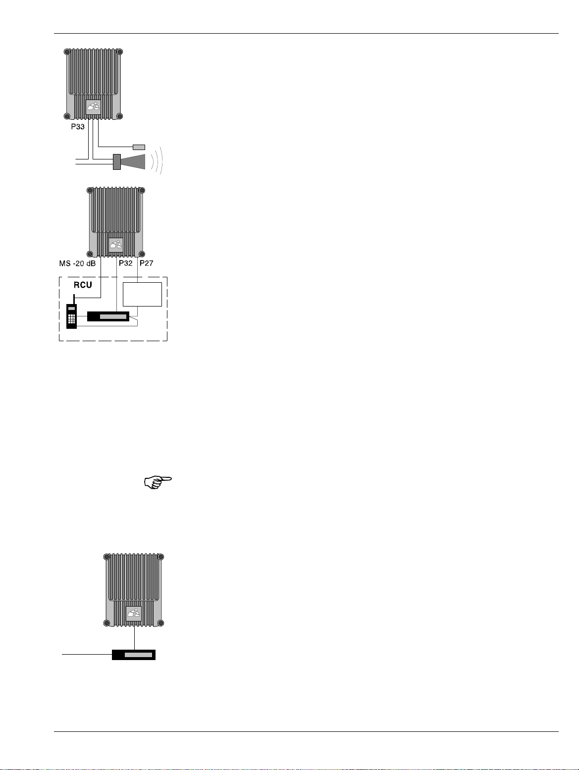
3. Connect external alarm sensors (burglary, fire, etc.) and other
external alarm equipment (optical or acoustic signal, etc.), if any.
Cables for this installation is taken through free strain relief
bushings on the bottom of the repeater, in the same way as the
mains cable and the antenna cables.
ALLGON
External
alarm sensors
External alarm is connected to the P33 alarm port located to the left
in the cabinet (see Figure 3-7 on page 3-9). Use a 15 pole D-sub male
connector.
The P33 port is described on page 3-11.
4. Connect the internal phone/modem unit for remote control of the
repeater, if any.
The modem and a power backup unit are integrated in an RCU,
ALLGON
Remote Control Unit, which is mounted downmost inside the cabinet,
in front of the PSU. The RCU is available in different types for
various systems, which is further detailed in the Optional section in
Chapter 13.
Battery
Modem
Power supply
This is a schematic figure.
The various RCU parts can
be integrated or configured
differently.
ALLGON
P32
Telephone line
Modem
The modem is connected to the P32 modem port (RS-232, V.24
interface) on the repeater located to the left in the cabinet (see
Figure 3-7 on page 3-9).
The P32 port is described on page 3-11.
The mobile phone antenna is connected to the MS –20dB port on the
BS directional coupler (DC) located to the right in the cabinet
(DC/BS), provided that the phone and the repeater operate in the
same system.
If an RCU is used, this is powered by the P27 auxiliary port located
to the left in the cabinet (see Figure 3-7 on page 3-9). Pin 2 and 3 of
the P27 port are interconnected with a jumper if not used. This
jumper must be removed before plugging the RCU connector to P27.
If the RCU is removed, the jumper between pin 2 and 3 on the P27
port must be reconnected. Otherwise, the CU and ALI boards will
have no voltage supply. Do not connect the jumper to another position
than between pin 2 and 3 on the P27 port.
The P27 port is described on page 3-10.
5. Connect a telephone line for remote control of the repeater, if any.
The telephone line is connected to a modem, which is connected to
the P32 modem port on the repeater.
The P32 port is described on page 3-11.
Use a free strain relief bushing at the bottom of the repeater for the
external telephone line cable.
User’s Manual VD202 90/EN Rev. 1A 1999-07 3 - 7
Page 29

ALLGON System AB AR Repeaters & OMT32 Hardware – Installation
6. Connect the Repeater to Repeater Link cable, if this optional feature
is to be used. The R2R net cable is connected to the P34 Repeater to
Repeater Link port on the repeater via a connector board to the right
ALLGON ALLGON
in the repeater.
The P34 Repeater to Repeater Link port is described on page 3-13.
A free strain relief bushing at the bottom of the repeater is used for
the external net cable.
Necessary information for a Repeater to Repeater Link installation is
found in the VD202 91/EN, R2R, Repeater to Repeater Link Kit,
Installation Guide.
7. Connect a PC for controlling the repeater. A COM port on the PC is
connected to the P31 PC port (RS-232) located to the right in the
cabinet (see Figure 3-7 on page 3-9). Use the provided serial cable.
ALLGON
Port P31 is described on page 3-10.
Now, you can use the OMT32 program to set up and control the
repeater. The OMT32 program is described in part two of this
manual.
But first, check the connections made and commission the repeater as
described in Chapter 4.
User’s Manual VD202 90/EN Rev. 1A 1999-07 3 - 8
Page 30

ALLGON System AB AR Repeaters & OMT32 Hardware – Installation
Connection Ports and Station Ground
The DIA distribution board provides most of the internal connection
between the repeater units, and to external ports. Connectors involved in
the installation are also located on the DIA board. These connectors are
described below. A complete DIA board connector list is found in the
Board and Unit Descriptions section in Chapter 5.
Station ground is detailed below as well.
OUT
IN ATT +7V OUT1 OUT2
LNA
LOW
UL
CMB CMB
DL UL
DPX DPX
MS
LNA
DL
OUT
LOWIN+7V ATTOUT1 OUT2
BS
P28
P34
P32
P33
P27
DC
DPX
TEST
-30 dB
MS
-20 dB
ANT
DC
DPX
TEST
-30 dB
MS
-20 dB
ANT
MS BS
Figure 3-7. Connection ports and station ground
P31
DC
MS
-20 dB
Station Ground
There is a station ground screw (M8) in the repeater marked with a
ground symbol (see Figure 3-7). This screw must be used only for station
grounding (if such ground is to be used).
User’s Manual VD202 90/EN Rev. 1A 1999-07 3 - 9
Page 31

ALLGON System AB AR Repeaters & OMT32 Hardware – Installation
P27 Auxiliary Port
8
1
Auxiliary port P27 is used for powering an RCU mobile phone/modem
remote control unit. The connector is found on the DIA board to the left
in the cabinet (see Figure 3-7).
P27 is an 8 pole, 1 line male connector.
Pin 2 and 3 of the P27 port MUST ALWAYS be interconnected to provide
the CU and ALI boards with voltage supply. If there is no cable connected
to the P27 port, pin 2 and 3 MUST be interconnected with a jumper.
P27 auxiliary connector pinning
Pin 1 +7V DC
Pin 2 +7V DC
Pin 3 CU and ALI power supply from pin 2
Pin 4 GND
Pin 5 +26V DC or +10V DC depending on the repeater type
Pin 6 Not used
Pin 7 Output 200KHz reference
Pin 8 GND
P31 PC Port
9
6
PC port P31 is a RS-232 port used for local PC communication.
5
The connector is found on the DIA board to the right in the cabinet (see
Figure 3-7).
1
P31 is a 9 pole D-sub female connector.
P31 PC connector pinning
Pin 1 Not used
Pin 2 Data from repeater to OMT32
Pin 3 Data from OMT32 to repeater
Pin 4 DTR from OMT32 to repeater
Pin 5 GND
Pin 6 DSR from repeater to OMT32
Pin 7 RTS from OMT32 to repeater
Pin 8 CTS from repeater to OMT32
Pin 9 Not used
User’s Manual VD202 90/EN Rev. 1A 1999-07 3 - 10
Page 32

ALLGON System AB AR Repeaters & OMT32 Hardware – Installation
P32 Modem Port
Modem port P32 is a RS-232 port with V.24 interface used for remote
6
1
control of the repeater.
9
5
P33 Alarm Port
15
8
The connector is found on the DIA board to the left in the cabinet (see
Figure 3-7).
P32 is a 9 pole D-sub male connector.
P32 modem connector pinning
Pin 1 DCD
Pin 2 RXD
Pin 3 TXD
Pin 4 DTR
Pin 5 GND
Pin 6 DSR
Pin 7 RTS
Pin 8 RFS
Pin 9 RI
Alarm port P33 is used for external alarm sensors and alarm equipment.
The connector is found on the DIA board to the left in the cabinet (see
Figure 3-7).
P33 is a 15 pole D-sub female connector.
9
1
The port has four alarm inputs, EAL1 - EAL4, and two alarm outputs.
Four alarm inputs
The inputs are low-level inputs (signal AI1 - AI4) with common ground
(AIC).
Use insulated switch or relay to initiate alarms (open switches in normal
operating mode, closed switches cause alarm).
The alarm switch connection can be toggled between being active open or
active closed. See the Alarm Configuration section in Chapter 11.
The alarm input voltage ratings, related to ground (AIC), are:
max
min
= 5.5V
= –0.5V
Vin
Vin
The alarm inputs are defined as follows:
Pin 14 AI1 External alarm input 1 - EAL1
Pin 15 AI2 External alarm input 2 - EAL2
Pin 7 AI3 External alarm input 3 - EAL3
Pin 8 AI4 External alarm input 4 - EAL4
Pin 6 AIC Ground
User’s Manual VD202 90/EN Rev. 1A 1999-07 3 - 11
Page 33

ALLGON System AB AR Repeaters & OMT32 Hardware – Installation
P28 - AI4 door switch alarm input
3
1
Normally, alarm input AI4 is used for repeater cover opening alarm
EAL4, which is arranged using a door switch (optional). Because of that,
AI4 and AIC are available also in the P28 connector, to which the door
switch is connected. The location of the connector in the cabinet is shown
in Figure 3-7.
The EAL4 door switch alarm is activated 10-30 seconds after the cover
has been opened.
The other external alarms are activated 1 sec. after initiation.
Two alarm outputs
Both the alarm outputs are 1 pole closing and 1 pole opening relay
outputs insulated from each other.
Maximum ratings, related to ground or any other alarm terminal, are
50VAC/60VDC.
The alarm outputs are defined as follows:
Pin 9-1 AO1-AO8 Closed when operating, otherwise open
Pin 10-2 AO6-AO7 Open when operating, otherwise closed
Pin 11-3 AO2-AO5 Closed at alarm state, otherwise open
Pin 12-4 AO3-AO4 Open at alarm state, otherwise closed
15
Alarms are activated by CRITICAL and ERROR alarms.
P33 alarm connector pinning
Pin 1 AO8
8
9
1
Pin 2 AO7
Pin 3 AO5
Pin 4 AO4
Pin 5 Not used
Pin 6 AIC
Pin 7 AI3
Pin 8 AI4
Pin 9 AO1
Pin 10 AO6
Pin 11 AO2
Pin 12 AO3
Pin 13 Not used
Pin 14 AI1
Pin 15 AI2
User’s Manual VD202 90/EN Rev. 1A 1999-07 3 - 12
Page 34

ALLGON System AB AR Repeaters & OMT32 Hardware – Installation
P34 Repeater to Repeater Link Port
The P34 port is used for Repeater to Repeater Link (R2R net), which is an
optional feature for the AR repeaters.
The connector is found on the DIA board to the left in the cabinet (see
Figure 3-7).
P34 is an 8 pole RJ45 modular female connector.
P34 Repeater to Repeater Link connector pinning
Pin 1 C/S
Pin 2 GND
Pin 3 D–
Pin 4 D+
Pin 5 D+
Pin 6 D–
Pin 7 GND
Pin 8 C/S
For further information about the Repeater to Repeater Link installation,
refer to the VD202 91/EN R2R, Repeater to Repeater Link Kit, Installation
Guide.
User’s Manual VD202 90/EN Rev. 1A 1999-07 3 - 13
Page 35

ALLGON System AB AR Repeaters & OMT32 Hardware – Installation
Mains Breakdown Relay
To be able to distinguish PSU faults from power failure, a mains
breakdown relay must be used on the repeater mains supply.
The mains breakdown relay is not included in the repeater. So, it has to
be mounted outside the repeater chassis. The relay intended for this
purpose must fulfil the following specifications:
Relay specification
Closing time: max. 30 milliseconds
Insulation coil/contact: min. 4KV
Mains connected relay must be in compliance with valid local regulations.
Connection
• Connect a normally closed relay contact to pin AI1 and AIC on the P33
alarm connector (closed contact at no current). Alarm is initiated by
short circuiting the AI1 and AIC inputs as shown in Figure 3-8. The
P33 alarm connector is detailed on page 3-11.
• Connect the relay coil. It must be supplied from the same fuse as the
repeater.
ALLGON
Figure 3-8. Mains breakdown relay connection
• After commissioning, select the Mains breakdown option in the
Alarm Configuration dialog box described in the Alarm Configuration
section in Chapter 11.
User’s Manual VD202 90/EN Rev. 1A 1999-07 3 - 14
Page 36

ALLGON System AB AR Repeaters & OMT32 Hardware – Installation
Installing 24 Volt or 48 Volt DC Power Supply Unit
You can replace the 220V AC PSU with a 24 Volt or 48 Volt DC PSU as
follows:
DC
DPX
TEST
-30 dB
MS
-20 dB
ANT
DC
DPX
TEST
-30 dB
MS
-20 dB
ANT
Figure 3-9. Replacing the PSU
1. Switch the repeater off and remove the mains plug from the PSU
(’1’ in Figure 3-9).
2. Disconnect the two connectors (2) on the PSU.
3. Loosen the three fixing screws (3) using a 5mm Allen key.
4. Remove the PSU from the repeater.
5. Mount the 24/48 Volt DC PSU with the three fixing screws (3).
6. Connect the PSU to the DIA board (2).
BROWN BLUE
7. Connect the DC power cable. The supplied cable should have a
radiation limiter. The cable shall be connected as follows:
The + pole shall be connected to one of the left terminals in the PSU
connector with the BROWN part of the DC cable.
The – pole shall be connected to one of the right terminals in the
PSU connector with the BLUE part of the DC cable.
8. Switch the repeater on.
9. The yellow LED on the PSU shall now be lit.
The DC Power Supply Unit must be galvanically separated from the mains
supply with an equipment fulfilling the IEC65 safety requirements.
User’s Manual VD202 90/EN Rev. 1A 1999-07 3 - 15
Page 37

ALLGON System AB AR Repeaters & OMT32 Hardware – Commissioning
4
. Commissioning
Read carefully Chapter 1 Safety before commissioning the repeater.
Check all connections made during the installation. Also, ensure that
both the mains plugs for repeaters equipped with two power supply units
are connected to outlets supplied from the same fuse.
To fulfill the IP65 weather protective requirements, ensure that the cable
strain relief bushings are properly tightened. Also, ensure that the gaskets
at the cable inlets and on the cabinet are properly fitted and not damaged.
When the installation is checked, commission the repeater as described
below.
User’s Manual VD202 90/EN Rev. 1A 1999-07 4 - 1
Page 38

ALLGON System AB AR Repeaters & OMT32 Hardware – Commissioning
Starting the Repeater
1. Turn the mains switch on (marked ’S’ in Figure 4-1).
2. Check the LED on the power supply unit (V). It must be lit with a
steady yellow light.
3. Check the four CU board LEDs (see Figure 4-1). A correct power
up is indicated as follows:
PWR
Yellow LED which is lit with a steady light after the mains is
switched on. Indicates present power.
BOOT
Red LED which is lit with a steady light when the system boots, i.e.
for 10 - 15 seconds after the mains is switched on. Then, it flashes
for the next 5 - 10 seconds. After that, if no error is detected, the
LED is off.
ALARM
Red LED which flashes 15 - 20 seconds after the mains is switched
on. Then, it flashes for less serious alarms (ERROR) and is lit with a
steady light for fatal alarms (CRITICAL).
OPER
Green LED which lights up approx. 15 seconds after the mains is
switched on. It shows, with a steady light, that the repeater is ready
for operation.
4. Check the three ALI board LEDs (see Figure 4-1). The LEDs follow
the alarm relays. A correct power up is indicated as follows:
OPER
Green LED which has the same indication as the green LED on the
CU board (see above).
ALARM
Red LED which is lit with a steady light for ERROR and CRITICAL
alarms.
PWR
Yellow LED which has the same indication as the yellow LED on the
CU board (see above).
External indicators on the repeater front
Yellow
Operation LED which lights up approx. 15 seconds after the mains is
switched on. At steady light the repeater is ready for operation.
Red
Alarm LED which indicates ERROR alarms with flashing light and
CRITICAL alarms with steady light.
User’s Manual VD202 90/EN Rev. 1A 1999-07 4 - 2
Page 39

ALLGON System AB AR Repeaters & OMT32 Hardware – Commissioning
When the indicators show operational mode, the repeater can be
configured for operation by using an OMT32/PC. This is further detailed
in the Repeater Configuration section in Chapter 10
Indicators
OUT
IN ATT +7V OUT1 OUT2
LNA
LOW
UL
LNA
DL
OUT
LOWIN+7V ATTOUT1 OUT2
DC
-30 dB
-20 dB
DPX
TEST
ANT
MS
CU
DC
TEST
-30 dB
BS
ALI
DC
TEST
-30 dB
MS
DC
DPX
TEST
-30 dB
MS
-20 dB
ANT
OPER
ALARM
S
PWR
PWR
BOOT
V
OPER
ALARM
Figure 4-1. Indicators and mains switch
Figure 4-1 shows the repeater indicators and the mains switch. There are
also two external indicators on the repeater front cover.
Repeater to Repeater Link
indicators
Additional indicators are found in the repeater, if equipped with the
Repeater to Repeater Link feature. For information about these indicators,
refer to the VD202 91/EN R2R, Repeater to Repeater Link Kit, Installation
Guide.
User’s Manual VD202 90/EN Rev. 1A 1999-07 4 - 3
Page 40

ALLGON System AB AR Repeaters & OMT32 Hardware – Commissioning
Measuring the Output Power Level
Uplink and downlink output power test ports are found on the directional
couplers (DC) at the MS and BS antenna connectors. These test ports are
marked TEST –30dB (see Figure 4-1) and are intended for measuring
using e.g. a spectrum analyzer.
The coupling is –30dB approximately. There is no directivity in these test
ports, i.e. both uplink and downlink signal can be measured.
Voltage Supply Testpoints
A number of voltage supply testpoints are available in the repeater.
These testpoints are named U7A - U7F for the 7V supply voltages and
U26 for the 26V or 10V supply voltage (26V or 10V depending on the
repeater type).
A standard multi-meter can be used on these testpoints.
The testpoints are found on the DIA board in the repeater cabinet. The
testpoint positions on the DIA board is detailed in the Board and Unit
Descriptions section in Chapter 5.
If the repeater is equipped with a second PSU, e.g. for combined
channel/band selective operation, the same set of testpoints are found on
the cover DIA board as well.
Repeater Adjustment
The repeater is now ready to be adjusted in accordance with the site
conditions and system performance requirements. Pay especial attention
to the antenna isolation described in the Operational Status section in
Chapter 10.
User’s Manual VD202 90/EN Rev. 1A 1999-07 4 - 4
Page 41

ALLGON System AB AR Repeaters & OMT32 Hardware – Functional Description
5
. Functional Description
Allgon repeaters work as bi-directional on-frequency amplifiers.
A repeater receives, amplifies, and retransmits signals downlink and
uplink simultaneously, i.e. from the base station via the repeater to the
mobile stations and from the mobile stations via the repeater to the base
station.
The repeater is connected to a BS antenna, directed towards the base
station, and to a MS antenna directed towards the area to be covered.
These antennas are connected to the repeater with N type male
connectors.
To prevent instability due to poor antenna isolation, a built-in antenna
isolation supervision feature reduces the gain level automatically when
poor antenna isolation is detected.
The Allgon repeaters are controlled by powerful microprocessors.
Alarm and operational LEDs are visible on the repeater front.
The repeater works with convection cooling without fan.
Operational parameters such as gain, channel number, power levels, etc.
are set using a desktop or notebook and the Allgon OMT32, which
communicate, locally or remotely via modem, with the repeater control
unit (CU). Remote operation is performed using a telephone line or a
built-in mobile phone equipped with a data interface.
User’s Manual VD202 90/EN Rev. 1A 1999-07 5 - 1
Page 42

ALLGON System AB AR Repeaters & OMT32 Hardware – Functional Description
Repeater Design
The repeater is housed in a cast aluminium chassis that is waterproof,
class IP65, for outdoor use. The chassis has a design suited for outdoor
use as well as indoor use.
The chassis consists of a cabinet and a cover joined with hinges. The
cabinet contains the repeater circuitry. The cover can either be a thin
cover or a large cover. The latter consists of another cabinet which can
be used as an empty cover or be equipped as an independent repeater
system.
The cover has two external LEDs for operation and alarm indication.
The cabinet as well as a large cover can be equipped for channel selective
operation or band selective operation. A combined repeater is normally
equipped for channel selective operation in the cabinet and band selective
operation in the cover.
Different amplifier boards are used to get the various operations (see
below). The amplifier boards are individually shielded and located under
metal cover sheets which can be folded out.
Channel selective GSM amplifier boards
Channel selective GSM repeaters can handle up to eight repeater channels
(four if the CU part number is K103/1). For every even number of
repeater channels, two CHA amplifier boards are required in the repeater,
one CHA board for uplink signaling and one board for downlink signaling.
Each repeater channel is allocated to a radio channel or switched off. In a
GSM type TDMA system (GSM, EGSM, DCS1800 or PCS1900), one
repeater channel can handle eight calls (sixteen if half-rate encoding is
used).
Channel selective CDMA amplifier boards
Current CDMA repeaters can handle two CDMA repeater channels. For
every even number of repeater channels, two CSA amplifier boards and
two PA amplifier boards are required in the repeater, one pair of CSA/PA
boards for uplink signaling and one pair for downlink signaling. Each
repeater channel is allocated to a radio channel or switched off.
Band selective amplifier boards
Band selective repeaters can handle one wide band repeater channel. The
band width is either fixed or adjustable (fixed for 900MHz repeaters only).
A band selective repeater channel requires two BSA boards and two PA
amplifier boards in the repeater. One pair of BSA/PA boards for uplink
signaling and one pair for downlink signaling.
User’s Manual VD202 90/EN Rev. 1A 1999-07 5 - 2
Page 43

ALLGON System AB AR Repeaters & OMT32 Hardware – Functional Description
Other boards
In addition to the channel/band selective boards, the repeater contains:
• DIA Distribution board, which is a board on which all other boards and
units are connected to.
On the DIA board, there is a shielded metal frame in which CU and
ALI boards are located.
There is a DIA board in the cabinet, and another board in the cover, if
equipped.
• CU Control Unit board, located in the frame on the DIA board.
There is one CU board in the cabinet, which controls the entire
repeater.
• ALI Alarm Interface board, located in the frame on the DIA board.
There is one ALI board in the cabinet which handles alarm and alarm
communication.
• DC Directional Coupler, located in shielded boxes which are formed as
recesses in the cabinet.
Two DC units in the cabinet are used as antenna signal directional
coupler.
• LNA Low Noise Amplifier, located in shielded boxes which are formed
as recesses in the cabinet.
Two LNA units in the cabinet are used as downlink and uplink low
noise amplifiers, and additional two LNA are used in the cover, if
equipped.
• DPX Duplex filter, located on the cover plate over the channel/band
selective boards.
• CMB Combiner unit, located on the cover plate over the channel/band
selective boards in channel selective repeaters with more than two
channels, and in combined repeaters.
• PSU Power Supply Unit, located downmost in the cabinet, and in the
cover, if equipped.
If the repeater is equipped with an optional Repeater to Repeater Link
feature, the following board is also included in the repeater (not valid to
channel selective CDMA repeaters):
• RIA Repeater to Repeater Interface Adapter, located in the frame on
the DIA board.
For further information about the Repeater to Repeater Link feature, refer
to the VD202 91/EN R2R, Repeater to Repeater Link Kit, Installation
Guide.
User’s Manual VD202 90/EN Rev. 1A 1999-07 5 - 3
Page 44

ALLGON System AB AR Repeaters & OMT32 Hardware – Functional Description
Channel Selective GSM Repeater
LNA UL
Uplink
CMB
Downlink
DPX
MS
RIA
CU
ALI
DC
MS
LNA DL
Downlink
123 4
CHA1
DL
(2 ch.)
MS
Mobile station
antenna
CHA2
DL
(2 ch.)
CHA3
UL
(2 ch.)
PSU
Base station
CHA4
UL
(2 ch.)
BS
antenna
567 8
CHA5
DL
(2 ch.)
DC
BS
CHA6
DL
(2 ch.)
CMB
Uplink
CHA7
UL
(2 ch.)
CHA8
UL
(2 ch.)
DPX
BS
Figure 5-1. Channel selective GSM repeater
A cabinet (the left part in Figure 5-1) for a channel selective GSM
repeater can be equipped with four CHA channel boards, two downlink
boards (DL) with two internal channels each and two uplink boards (UL)
with two internal channels each. The described cabinet has a capacity of
four bi-directional GSM channels.
The cover (the right part in Figure 5-1) can be equipped as well, which
gives up to eight GSM channels. The cover board positions are shown in
the figure.
Channel selective GSM repeaters are used for GSM, DCS and PCS types
of TDMA systems.
Main units: ALI Alarm Interface board
CHA Channel Selective Amplifier board, GSM type
CMB Combiner unit
CU Control Unit board
DC Directional Coupler
DPX Duplex filter
LNA Low Noise Amplifier
PSU Power Supply Unit
RIA Repeater to Repeater Interface Adapter (optional)
User’s Manual VD202 90/EN Rev. 1A 1999-07 5 - 4
Page 45

ALLGON System AB AR Repeaters & OMT32 Hardware – Functional Description
Channel Selective CDMA Repeater
LNA UL
Uplink
DPX
MS
CU
ALI
DC
MS
LNA DL
Downlink
123 4
CSA
DL
(2 carr.)
MS
Mobile station
antenna
PA
DL
CSA
UL
(2 carr.)
PSU
Base station
PA
UL
BS
antenna
567 8
CSA
DL
(2 carr.)
DC
BS
PA
DL
CSA
UL
(2 carr.)
PA
UL
DPX
BS
Figure 5-2. Channel selective CDMA repeater
A cabinet (the left part in Figure 5-2) for a channel selective CDMA
repeater is equipped with two pair of CSA and PA boards, one pair for
downlink (DL) and one pair for uplink (UL). The described cabinet has a
capacity of two bi-directional CDMA carriers.
The cover (the right part in Figure 5-2) can be equipped as well. The
cover board positions are shown in the figure.
CSA boards are used for IS-95 or J-STD-008 types of CDMA systems.
Main units: ALI Alarm Interface board
CSA Channel Selective Amplifier board, CDMA type
CU Control Unit board
DC Directional Coupler
DPX Duplex filter
LNA Low Noise Amplifier
PA Power Amplifier board
PSU Power Supply Unit
User’s Manual VD202 90/EN Rev. 1A 1999-07 5 - 5
Page 46

ALLGON System AB AR Repeaters & OMT32 Hardware – Functional Description
Band Selective Repeater
LNA UL
Uplink
DPX
MS
RIA
CU
ALI
DC
MS
LNA DL
Downlink
123 4
BSA
DL
MS
Mobile station
antenna
PA
DL
BSA
UL
PSU
Base station
PA
UL
BS
antenna
567 8
BSA
DL
DC
BS
PA
DL
BSA
UL
PA
UL
DPX
BS
Figure 5-3. Band selective repeater
A cabinet (the left part in Figure 5-3) for a band selective repeater is
equipped with two pair of BSA and PA boards, one pair for downlink (DL)
and one pair for uplink (ULS). The described cabinet is equipped for
bi-directional band selective operation.
The cover (the right part in Figure 5-3) can be equipped as well. The
cover board positions are shown in the figure.
BSA boards are used for band selective systems either with a fixed band
width of 900MHz or an adjustable band width.
Main units: ALI Alarm Interface board
BSA Band Selective Amplifier board, fixed or adjustable band width
CU Control Unit board
DC Directional Coupler
DPX Duplex filter
LNA Low Noise Amplifier
PA Power Amplifier board
PSU Power Supply Unit
RIA Repeater to Repeater Interface Adapter (optional)
User’s Manual VD202 90/EN Rev. 1A 1999-07 5 - 6
Page 47

ALLGON System AB AR Repeaters & OMT32 Hardware – Functional Description
Combined Repeater
LNA UL
Uplink
CMB
Downlink
DPX
MS
RIA
CU
ALI
DC
MS
LNA DL
Downlink
1234
CHA1
DL
(2 ch.)
MS
Mobile station
antenna
CHA2
DL
(2 ch.)
CHA3
UL
(2 ch.)
PSU1
Base station
CHA4
UL
(2 ch.)
BS
antenna
LNA UL
Uplink
LNA DL
Downlink
567 8
BSA
DL
DC
BS
PA
DL
PSU2
CMB
Uplink
BSA
UL
PA
UL
DPX
BS
Figure 5-4. Combined repeater
Figure 5-4 shows an example of a combined channel selective and band
selective repeater. The channel selective part is located in the cabinet and
the band selective part in the cover.
This example has four bi-directional GSM channels and band selective
operation.
Any combinations of channel selective GSM part (page 5-4), channel
selective CDMA part (page 5-5) and band selective part (page 5-6) can be
mixed.
Main units: ALI Alarm Interface board
BSA Band Selective Amplifier board, fixed or adjustable band width
CHA Channel Selective Amplifier board, GSM type
CMB Combiner unit
CU Control Unit board
DC Directional Coupler
DPX Duplex filter
LNA Low Noise Amplifier
PA Power Amplifier board
PSU1,2 Power Supply Unit 1 and 2
RIA Repeater to Repeater Interface Adapter (optional)
User’s Manual VD202 90/EN Rev. 1A 1999-07 5 - 7
Page 48

ALLGON System AB AR Repeaters & OMT32 Hardware – Functional Description
Block Diagram
The following block diagrams are found in this section:
• Channel selective GSM repeater, Figure 5-5 on page 5-10.
• Channel selective CDMA repeater, Figure 5-6 on page 5-12.
• Band selective repeater, Figure 5-7 on page 5-14.
Some of the most important features and functions are described below.
The main signal paths for the repeater types are described under the
block diagrams.
Downlink
The downlink signal path, i.e. from the base station through the repeater
to the mobile station, is described for channel selective GSM operation,
channel selective CDMA operation, and band selective operation under the
block diagrams on the following pages.
Uplink
Repeater Setup
The uplink signal path, i.e. from the mobile station through the repeater
to the base station, is identical to the downlink path the other way round.
Only some levels and component values differ.
The repeater parameters can be set locally by means of a desktop or
notebook loaded with the OMT32 software (or the OMS software). The
PC or notebook is connected to the CU via the P31 serial RS-232 PC port
(see Figure 5-5, Figure 5-6 and Figure 5-7).
The repeater parameters can also be set remotely by means of a phone
(mobile or via a telephone line) and a modem connected to the CU board
via the P32 modem serial RS-232 port (see Figure 5-5, Figure 5-6 and
Figure 5-7).
User’s Manual VD202 90/EN Rev. 1A 1999-07 5 - 8
Page 49

ALLGON System AB AR Repeaters & OMT32 Hardware – Functional Description
Alarm
Alarm signals from external sensors are received by the ALI board, which
forwards the alarm signals to the CU board.
The software on the CU board is able to activate acoustic or visual alarm
or direct the alarm to the P33 alarm RS-232 port to be forwarded, via
modem and telephone, to an OMT32/PC (or OMS/PC) located in an
operation and maintenance central.
Alarms can be configured from an OMT32/PC (or from an OMS/PC).
User’s Manual VD202 90/EN Rev. 1A 1999-07 5 - 9
Page 50

ALLGON System AB AR Repeaters & OMT32 Hardware – Functional Description
Channel Selective GSM Repeater
TEST -30 dB
BS antenna
Base station
MSC
Telephone
line
Modem
CHANNEL SELECTIVE
GSM REPEATER
LNA
DL
DPX
PSU
BS
CMB
UL
ALI
P32 P31 P33
RCU
Modem
Battery
DC
BS
MS -20 dB P27
CHA1 - DL
CHA2 - DL
CHA3 - UL
CHA4 - UL
CU
Power
supply
CMB
DL
LNA
UL
DPX
MS
RIA
ALI
DC
MS
TEST -30 dB
MS antenna
P34
External
alarm sensors
ALLGON
ALLGON
ALL
ALL
Figure 5-5. Block diagram, channel selective repeater
Figure 5-5 shows a block diagram of a channel selective repeater with four
bi-directional channels. This diagram is applicable to repeaters for the
GSM, DCS/PCN and GSM 1900 (PCS) systems.
Downlink
The signal from the base station is received via the repeater BS antenna
and is then forwarded through a directional coupler (DC). The signal
passes a duplex filter (DPX), is amplified in a low noise amplifier (LNA),
and enters the channel boards (CHA), which have two parallel channels
each.
User’s Manual VD202 90/EN Rev. 1A 1999-07 5 - 10
Page 51

ALLGON System AB AR Repeaters & OMT32 Hardware – Functional Description
The first mixer stage on the CHA amplifier board, which is controlled by
a synthesizer, converts the received frequency down to the IF frequency.
The signal is then filtered by a SAW bandpass filter and, not shown in the
figure, amplified before it is fed to the second mixer stage, controlled by
the same synthesizer as the previous one, for converting back to the
original frequency.
The output signal from the mixer is then amplified in the power amplifier
and fed to a combiner, which combines the signals from the two channels
on the channel board.
The output signal passes a combiner (CMB), a duplex filter (DPX), and a
directional coupler (DC), before it is fed to the repeater MS antenna.
User’s Manual VD202 90/EN Rev. 1A 1999-07 5 - 11
Page 52

ALLGON System AB AR Repeaters & OMT32 Hardware – Functional Description
Channel Selective CDMA Repeater
TEST -30 dB
BS antenna
Base station
MSC
Telephone
line
Modem
CHANNEL
SELECTIVE
LNA - DL
CDMA
REPEATER
DPX
DC
BS
MS -20 dB P27
BS
PSU ALI
P32 P31 P33
RCU
Modem
PA - UL
CSA - UL
CSA - DL
CU
LNA - UL
DPX
MS
TEST -30 dBPA - DL
MS antenna
DC
MS
ALI
External alarm
sensors
Power
Battery
supply
Figure 5-6. Block diagram, CDMA repeater
Figure 5-6 shows a block diagram of a channel selective CDMA repeater.
This diagram is applicable only to repeaters for the CDMA system.
Downlink
The signal from the base station is received via the repeater BS antenna
and is then forwarded through a directional coupler (DC). The signal
passes a duplex filter (DPX), is amplified in a low noise amplifier (LNA),
and enters the channel board (CSA), which has two parallel channels.
User’s Manual VD202 90/EN Rev. 1A 1999-07 5 - 12
Page 53

ALLGON System AB AR Repeaters & OMT32 Hardware – Functional Description
The first mixer stage on the CSA amplifier board, which is controlled by a
synthesizer, converts the received frequency down to the IF frequency.
The signal is then filtered by a SAW bandpass filter and, not shown in the
figure, amplified before it is fed to the second mixer stage, controlled by
the same synthesizer as the previous one, for converting back to the
original frequency.
The following power amplifier is controlled by the CU. The output gain
can be reduced to avoid instability due to poor antenna isolation.
The output signal from the amplifier is fed to a combiner, which combines
the signals from the two channels on the channel board.
A detector on the PA board measures continuously the output level. The
signal from this detector is used by the automatic gain control, AGC, to
supervise and, if necessary, reduce the output power to keep it under a
maximum level. The AGC gain control affects all the amplification stages.
The output signal passes a duplex filter (DPX) and a directional coupler
(DC) before it is fed to the repeater MS antenna.
User’s Manual VD202 90/EN Rev. 1A 1999-07 5 - 13
Page 54

ALLGON System AB AR Repeaters & OMT32 Hardware – Functional Description
Band Selective Repeater
TEST -30 dB
BS antenna
Base station
MSC
Telephone
line
Modem
BAND
SELECTIVE
LNA - DL
REPEATER
DPX
PSU
BS
RCU
PA - UL
BSA - UL LNA - UL
ALI
P32 P31 P33
Modem
DC
BS
MS -20 dB P27
CU
BSA - DL
PA - DL
DPX
MS
RIA
ALI
DC
MS
TEST -30 dB
MS antenna
P34
External alarm
sensors
ALLGON
ALLGON
ALL
ALL
Power
Battery
supply
Figure 5-7. Block diagram, band selective repeater
Figure 5-7 shows a block diagram of a band selective repeater. This
diagram is applicable to repeaters for e.g. NMT, TACS/ETACS and
AMPS/DAMPS systems.
Downlink
The signal from the base station is received via the repeater BS antenna
and is then forwarded through a directional coupler (DC). The signal
passes a duplex filter (DPX), is amplified in a low noise amplifier (LNA),
and enters the band selective amplifier board (BSA).
User’s Manual VD202 90/EN Rev. 1A 1999-07 5 - 14
Page 55

ALLGON System AB AR Repeaters & OMT32 Hardware – Functional Description
The first mixer stage on the BSA amplifier board, which is controlled by a
synthesizer, converts the received frequency down to the IF frequency.
The signal is then filtered by a SAW bandpass filter and, not shown in the
figure, amplified before it is fed to the second mixer stage, controlled by
the same synthesizer as the previous one, for converting back to the
original frequency.
The SAW filter can be either fixed or adjustable depending on the BSA
board used. If the BSA board has fixed band width, this SAW filter is
fixed and selected for the current band width. If the BSA board has
adjustable band width, the SAW filter can be software changed from
within OMT32 (or OMS) to cover various band widths.
The following power amplifier is controlled by the CU. The output gain
can be reduced to avoid instability due to poor antenna isolation.
A detector on the PA board measures continuously the output level. The
signal from this detector is used by the automatic gain control, AGC, to
supervise and, if necessary, reduce the output power to keep it under a
maximum level. The AGC gain control affects all the amplification stages.
The output signal passes duplex filter (DPX) and a directional coupler
(DC) before it is fed to the repeater MS antenna.
User’s Manual VD202 90/EN Rev. 1A 1999-07 5 - 15
Page 56

ALLGON System AB AR Repeaters & OMT32 Hardware – Functional Description
Board and Unit Descriptions
Cabling between boards and units is found on page 5-26.
DC - Directional Coupler
The directional couplers on the BS and MS sides are identical.
DC
DPX
TEST
-30 dB
MS
-20 dB
ANT
Connection
To the left in the cabinet DC/MS:
Port Connected to
DPX ANT on the DPX/MS duplex filter.
TEST –30dB Test port for the downlink output signal. This port has
MS –20dB Not used.
ANT MS antenna.
To the right in the cabinet DC/BS:
Port Connected to
DPX ANT on the DPX/BS duplex filter.
TEST –30dB Test port for the uplink output signal. This port has no
MS –20dB Mobile station antenna connection for remote control.
ANT BS antenna.
Figure 5-8. DC Directional coupler
no directivity.
directivity.
This port has at least 20dB directivity towards the
antenna.
User’s Manual VD202 90/EN Rev. 1A 1999-07 5 - 16
Page 57

ALLGON System AB AR Repeaters & OMT32 Hardware – Functional Description
DPX - Duplex Filter
The DPX duplex filters on the BS and MS sides are identical.
Connection
To the left in the cabinet DPX/MS:
Port Connected to
ANT DPX on the DC/MS directional coupler.
HI Channel selective GSM repeater:
Output on the CMB/DL combiner (at 4 channels),
P701 on the CHA1/DL channel board (at 2 channels).
Channel selective CDMA repeater:
P5 on the PA/DL board.
Band selective repeater:
P5 on the PA/DL board.
LO IN on the LNA/UL low noise amplifier.
To the right in the cabinet DPX/BS:
Port Connected to
ANT DPX on the DC/BS directional coupler.
HI IN on the LNA/DL low noise amplifier.
LO Channel selective GSM repeater:
Output on the CMB/UL combiner (at 4 channels),
P701 on the CHA3/UL channel board (at 2 channels)
Channel selective CDMA repeater:
P5 on the PA/UL board.
Band selective repeater:
P5 on the PA/UL board.
User’s Manual VD202 90/EN Rev. 1A 1999-07 5 - 17
Page 58

ALLGON System AB AR Repeaters & OMT32 Hardware – Functional Description
LNA - Low Noise Amplifier
The LNA low noise amplifiers are located in the outermost boxes at the
top of the cabinet and large cover (see Figure 5-1 to Figure 5-4 on
page 5-4 to 5-7). LNA/UL (uplink) is located to the left and LNA/DL
(downlink) to the right. All coaxial connectors are SMA type.
OUT
LNA
UL
Signals from the duplex filter output is fed to the LNA input connector
IN. Output OUT1 and OUT2 feed the CHA boards of the same signal
direction. The signal level in these connectors are +20dB referred to the
antenna input. Another output, OUT LOW, is an expansion output for an
additional LNA amplifier, if the repeater is equipped in the cover part of
the chassis. The gain to this connector is +2dB.
IN ATT +7VOUT1 OUT2
LOW
Figure 5-9. LNA low noise amplifier
LNA
DL
OUT
LOWIN+7V ATTOUT1 OUT2
The +7V input is used for 7V supply from the DIA board.
ATT is a control signal for a controllable attenuator in the LNA.
Connection
To the left in the cabinetLNA/UL:
Port Connected to
OUT LOW IN on the LNA/UL in the cover if equipped.
IN LO on the DPX/MS duplex filter.
ATT P23 on the DIA board.
+7V P23 on the DIA board.
OUT1 P101 on the CHA3/UL or CSA/UL or BSA/UL board.
OUT2 P101 on the CHA4/UL channel board.
To the right in the cabinetLNA/DL:
Port Connected to
OUT LOW IN on the LNA/DL in the cover if equipped.
IN HI on the DPX/BS duplex filter.
ATT P24 on the DIA board.
+7V P24 on the DIA board.
OUT1 P101 on the CHA1/DL or CSA/DL, or BSA/DL board.
OUT2 P101 on the CHA2/DL channel board.
Not used outputs do not need to be terminated.
User’s Manual VD202 90/EN Rev. 1A 1999-07 5 - 18
Page 59

ALLGON System AB AR Repeaters & OMT32 Hardware – Functional Description
CHA - Channel Amplifier Board for Channel Selective Operation
The cabinet can be equipped with four CHA Channel Amplifier boards.
These are numbered from left to right: CHA1 - CHA4. The board
positions CHA1 - CHA2 are used for downlink and CHA3 - CHA4 for
uplink (see Figure 5-1 on page 5-4). If the repeater is equipped with two
channels only, the board positions 1 and 3 are used.
The two internal channels on each CHA board are located to the left and
to the right on the board.
If a board is to be removed, the RFI filter at the board connector and the
two coaxial connectors must be removed prior to the board removal. No
heat compound is used on the heat sink body or on the chassis.
Coaxial connector P101 is the input of the CHA board fed from the LNA.
Coaxial connector P701 is the output of the board. The output signal is
fed to the duplex filter, either directly or via a CMB combiner, depending
on the repeater configuration.
Connection
Board #1 from the left CHA1/DL:
Port Connected to
P101 OUT1 on the LNA/DL low noise amplifier.
P701 Input on the CMB/DL combiner (at 4 channels) or
Board #2 from the left CHA2/DL:
Port Connected to
P101 OUT2 on the LNA/DL low noise amplifier.
P701 Input on the CMB/DL combiner.
Board #3 from the left CHA3/UL:
Port Connected to
P101 OUT1 on the LNA/UL low noise amplifier.
P701 Input on the CMB/UL combiner (at 4 channels) or
Board #4 from the left CHA4/UL:
Port Connected to
P101 OUT2 on the LNA/UL low noise amplifier.
P701 Input on the CMB/UL combiner.
HI on the DPX/MS duplex filter (at 2 channels).
LO on the DPX/BS duplex filter (at 2 channels).
Caution
The CHA Channel Amplifier board power transistors contain beryllium
oxide (BeO) that is poisonous. The power transistors are mounted with
two screws as opposed to other transistors. See Chapter 1, Safety.
BERYLLIUM OXIDE
User’s Manual VD202 90/EN Rev. 1A 1999-07 5 - 19
Page 60

ALLGON System AB AR Repeaters & OMT32 Hardware – Functional Description
CSA and PA Boards for Channel Selective CDMA Operation
For channel selective CDMA operation, the cabinet is normally equipped
with two CSA and two PA boards. These are numbered from left to right.
Board position 1 is used for CSA downlink board, position 2 for PA
downlink board, position 3 for CSA uplink board, and position 4 for PA
uplink board (see Figure 5-2 on page 5-5).
If a board is to be removed, the RFI filter at the board connector, the two
coaxial connectors, and the flat conductor cable between the CSA board
and the PA board must be removed prior to the board removal. No heat
compound is used on the heat sink body or on the chassis.
Coaxial connector P101 is the input of the CSA board fed from the LNA.
Coaxial connector P301 is the output of the CSA board. The signal from
this output is fed to the PA board input P4. The PA board output P5 is
fed to the duplex filter of the same signal direction.
Connection
Board #1 from left CSA/DL:
Port Connected to
P101 OUT1 on the LNA/DL low noise amplifier.
P301 P4 on the PA/DL board.
Board #2 from left PA/DL:
Port Connected to
P4 P301 on the CSA/DL board.
P5 HI on the DPX/MS duplex filter.
Board #3 from left CSA/UL:
Port Connected to
P101 OUT1 on the LNA/UL low noise amplifier.
P301 P4 on the PA/UL board.
Board #4 from left PA/UL:
Port Connected to
P4 P301 on the CSA/UL board.
P5 LO on the DPX/BS duplex filter.
Caution
The PA Power Amplifier board power transistors contain beryllium oxide
(BeO) that is poisonous. The power transistors are mounted with two
screws as opposed to other transistors. See Chapter 1, Safety.
BERYLLIUM OXIDE
User’s Manual VD202 90/EN Rev. 1A 1999-07 5 - 20
Page 61

ALLGON System AB AR Repeaters & OMT32 Hardware – Functional Description
BSA and PA Boards for Band Selective Operation
For band selective operation, the cabinet is equipped with two BSA and
two PA boards. These are numbered from left to right. Board position 1
is used for BSA downlink board, position 2 for PA downlink board,
position 3 for BSA uplink board, and position 4 for PA downlink board
(see Figure 5-3 on page 5-6).
If a board is to be removed, the RFI filter at the board connector, the two
coaxial connectors, and the flat conductor cable between the BSA board
and the PA board must be removed prior to the board removal. No heat
compound is used on the heat sink body or on the chassis.
Coaxial connector P101 is the input of the BSA board fed from the LNA.
Coaxial connector P301 is the output of the BSA board. The signal from
this output is fed to the PA board input P4. The PA board output P5 is
fed to the duplex filter of the same signal direction.
Connection
Board #1 from left BSA/DL:
Port Connected to
P101 OUT1 on the LNA/DL low noise amplifier.
P301 P4 on the PA/DL board.
Board #2 from left PA/DL:
Port Connected to
P4 P301 on the BSA/DL board.
P5 HI on the DPX/MS duplex filter.
Board #3 from left BSA/UL:
Port Connected to
P101 OUT1 on the LNA/UL low noise amplifier.
P301 P4 on the PA/UL board.
Board #4 from left PA/UL:
Port Connected to
P4 P301 on the BSA/UL board.
P5 LO on the DPX/BS duplex filter.
Caution
The PA Power Amplifier board power transistors contain beryllium oxide
(BeO) that is poisonous. The power transistors are mounted with two
screws as opposed to other transistors. See Chapter 1, Safety.
BERYLLIUM OXIDE
User’s Manual VD202 90/EN Rev. 1A 1999-07 5 - 21
Page 62

ALLGON System AB AR Repeaters & OMT32 Hardware – Functional Description
DIA Board
DIA is a distribution board for most of the boards, units and ports. The
DIA board is exclusively equipped with connectors. The connector types
are chosen to prevent unintentional mixing up.
P11 P12 P13 P14
P26
P34
P23
P32
U7F
P27
U7A U7B U7C U26
P28
P33
P5 P3
P4 P2
U7D
P22
P31
U7E
P21
P25
P24
GND
Figure 5-10. DIA board connectors and testpoints
Connection and connector types
Port Connected to Connector type
P2 CU board
P3 Not used
P4 ALI board
P5 Not used
P11 CHA1/DL or CSA/DL or BSA/DL 16 pole 1 line female
P12 CHA2/DL or PA/DL 16 pole 1 line female
P13 CHA3/UL or CSA/UL or BSA/UL 16 pole 1 line female
P14 CHA4/UL or PA/UL 16 pole 1 line female
P21 PSU - Power Supply Unit 10 pole 2 line male
P22 LED board in the cover 4 pole 1 line male
P23 LNA/UL 2 pole 1 line male
P24 LNA/DL 2 pole 1 line male
P25 Expansion output port to cover
circuitry if any. Only in cabinets.
P26 Expansion input port from the
cabinet. Used in equipped large
covers only.
*
P27 AUX1 auxiliary connector 8 pole 1 line male
P28 Door switch (internal alarm) 3 pole 1 line male
P31 PC (serial RS-232) 9 pole D-sub female
P32 Modem (serial RS-232) 9 pole D-sub male
P33 External alarm 15 pole D-sub female
P34 Repeater to Repeater Link 8 pole RJ45 modular female
*
Pin 2 and 3 on the P27 connector must be interconnected with a jumper
if the connector is not used.
16 pole 2 line male
16 pole 2 line male
User’s Manual VD202 90/EN Rev. 1A 1999-07 5 - 22
Page 63

ALLGON System AB AR Repeaters & OMT32 Hardware – Functional Description
Testpoints
Testpoint Voltage Purpose
U7A +7V DC CHA1/DL or CSA/DL or BSA/DL downlink
board supply voltage.
U7B +7V DC CHA2/DL or PA/DL downlink board supply
voltage.
U7C +7V DC CHA3/UL or CSA/UL or BSA/UL downlink
board supply voltage.
U7D +7V DC CHA4/UL or PA/UL downlink board supply
voltage.
U7E +7V DC LNA/UL and LNA/DL and P27 auxiliary port
supply voltage.
U7F +7V DC CU board and ALI board and RCU supply
voltage via the P27 auxiliary port jumper.
U26 +26V DC
or
+10V DC
GND 0 Ground
Power amplifiers and P27 auxiliary port supply
voltage (26V or 10V depending on the repeater
type).
DIA board part # and version
The DIA board part # is K105/1. Version R2A (containing the P34
connector) is required to use the optional Repeater to Repeater Link
feature.
User’s Manual VD202 90/EN Rev. 1A 1999-07 5 - 23
Page 64

ALLGON System AB AR Repeaters & OMT32 Hardware – Functional Description
CU Control Unit Board
The CU board is the central board in the repeater, located in the repeater
cabinet. The CU board contains a microprocessor, main memory, flash
memory for the CU software, EEPROM memory for parameters, memory
for the event log and statistics, a REFO reference oscillator, ports for local
and remote communication, battery powered real-time clock, etc.
The CU board is used to supervise and control operational parameters
such as gain control, channel handling, etc. The CU takes care of alarms
and the event log, password and logon, and many other procedures.
The CU is also a control interface when using an OMT32/PC or an
OMS/PC locally or remotely via modem.
The CU software can be downloaded from an OMT32/PC or OMS/PC
either locally or remotely via modem.
The real-time clock on the CU board is used for alarm and for the event
log.
There are currently two CU board variants: K103/1 and K103/2.
CU board and CU software part #s
K103/1 CU board (old)
K103/2 CU board (current) CU board K103/2 can be run with either the old SA102 01/2 CU software
CU board K103/1 can be run with the SA102 01/2 CU software. This
board can store one version of CU software. The repeater will always
boot on this software version.
or the current SA102 02/1 or SA102 02/2 CU software. This board can
store two versions of CU software, located in segment 1 and segment 2 of
the flash memory as Application 1 and Application 2. The repeater will
boot on that software which is set as Primary (description of Primary
application is found in the CU Revision Manager section in Chapter 10).
Compatibility for CU boards and CU software is detailed in the next
section.
Connection
The CU board is connected to the DIA board via the P2 port.
Caution
A lithium battery is permanently mounted on the CU board. Due to the
risk of explosion, this battery must not be removed from the board. In
case of battery malfunction, replace the CU board. The old CU board can
be sent to Allgon for repair.
User’s Manual VD202 90/EN Rev. 1A 1999-07 5 - 24
Page 65

ALLGON System AB AR Repeaters & OMT32 Hardware – Functional Description
Repeater CU Software and Hardware Compatibility
There are different versions of repeater CU software, which can be
combined with boards of various revisions. These have, however, unique
part numbers and revision information. Below, you will find a table of
repeater software currently available in combination with CU board
revisions.
CU Software
Part #
SA102 01/2 R2E K103/1
Latest
Software
Revision
Compatible
with
CU board
or
K103/2
Comments
For GSM channel selective
≤ 4 channels, band selective
800-900MHz fixed band
width only, and combi
(800/900MHz).
No traffic statistics.
SA102 02/1 R3A K103/2 For GSM, EGSM, DCS,
PCS channel selective
≤ 8 channels, band selective
800-900MHz fixed or
adjustable band width,
band selective 1800MHz or
1900MHz and combi.
Supports R2R link.
SA102 02/2 R1B* K103/2 For 800/1900MHz CDMA
≤ 2 channels.
R1B available August 1999 (800MHz CDMA added)
*
This information is updated 1999-07-01. As new versions of hardware
and software are released without prior noticing, contact your Allgon sales
representative if in doubt about the latest revision status.
For detailed information, refer to the release notes for the CU software to
be downloaded (normally found in the readme.txt file, which is supplied
with the program files).
User’s Manual VD202 90/EN Rev. 1A 1999-07 5 - 25
Page 66

ALLGON System AB AR Repeaters & OMT32 Hardware – Functional Description
Cabling
On the following pages, you will find cabling information for the various
repeater types:
• Channel selective GSM repeater, 2 channels (page 5-27)
• Channel selective GSM repeater, 4 channels (page 5-28)
• Channel selective CDMA repeater (page 5-29)
• Band selective repeater (page 5-30)
User’s Manual VD202 90/EN Rev. 1A 1999-07 5 - 26
Page 67

ALLGON System AB AR Repeaters & OMT32 Hardware – Functional Description
Channel Selective GSM Repeater, 2 Channels
HI
DPX
ANT
MS
LO HI
IN
ATT +7V OUT1 OUT2
OUT
LNA
LOW
UL
P101 P101
CHA1/DL CHA3/UL
P701 P701
116 116
116
DOOR
P28
3
1
1
P32
MS
DC
OUT
TEST 1
MS
IN/OUT
ANT
P33
16
P26
2
1
P23
LNA
UL
MODEM
EXT LARM
8
1
X
U
A
1
161 161 116
1
0
LO
DPX
ANT
BS
LNA
OUT1
DL
OUT2 +7V ATT
OUT
IN
LOW
1
P22
LED
PC
P31
BS
16
P25
2
1
DC
P24
LNA
DL
PSU
P21
10
OUT
TEST 1
MS
IN/OUT
1
ANT
MS BS
Power Supply Unit
Figure 5-11. Cabling, GSM repeater - 2 channels
Figure 5-11 shows a repeater equipped with the two channel boards
CHA1/DL and CHA3/UL for two bi-directional GSM channels.
User’s Manual VD202 90/EN Rev. 1A 1999-07 5 - 27
Page 68

ALLGON System AB AR Repeaters & OMT32 Hardware – Functional Description
Channel Selective GSM Repeater, 4 Channels
HI
DPX
MS
ANT
CMB
DL
CMB
UL
LO
OUT
OUT1
ATT +7V
OUT2
IN
LNA
LOW
UL
LNA
OUT1 OUT2 +7V ATT IN
DL
P101 P101 P101 P101
CHA1/DL CHA2/DL CHA3/UL CHA4/UL
P701 P701 P701 P701
116 161
DOOR
P28
3
1
1
P32 P33
MS
16
P26
2
1
DC
P23
LNA
OUT
UL
MODEM
EXT LARM
8
TEST 1
1
X
U
MS
A
IN/OUT
1
ANT
116116
1
0
161 116
LO
ANT
HI
DPX
BS
OUT
LOW
116116
1
P22
LED
PC
P31
BS
16
P25
2
1
P24
DC
LNA
DL
PSU
P21
10
OUT
TEST 1
MS
IN/OUT
1
ANT
MS BS
Power Supply Unit
Figure 5-12. Cabling, GSM repeater - 4 channels
Figure 5-12 shows a channel selective repeater equipped with the channel
boards CHA1/DL, CHA2/DL, CHA3/UL, and CHA4/UL for four
bi-directional GSM channels.
User’s Manual VD202 90/EN Rev. 1A 1999-07 5 - 28
Page 69

ALLGON System AB AR Repeaters & OMT32 Hardware – Functional Description
Channel Selective CDMA Repeater
DPX
MS
LOANT HI
OUT
ATT +7V OUT1 OUT2
IN
LNA
LOW
UL
P101
P4
CSA/DL
PA/DL
P301
1
2
0
9
1
1
16
116 161 161 116
DOOR
P28
3
1
1
P32 P33
MS
16
P26
2
1
DC
P23
LNA
UL
OUT
MODEM
EXT LARM
8
TEST 1
1
X
U
MS
A
IN/OUT
1
ANT
1
2
P5
0
9
1
1
16
1
0
CSA/UL
P301
1
P101
LNA
OUT1
OUT2 +7V ATT IN
DL
P4
1
2
0
9
1
16
P5
1
DPX
BS
OUT
LOW
PA/UL
1
2
0
9
1
P22
LED
PC
P31
PSU
P21
10
1
LOANT HI
16
1
BS
16
P25
2
1
P24
DC
LNA
DL
OUT
TEST 1
MS
IN/OUT
ANT
MS BS
Power Supply Unit
Figure 5-13. Cabling, CDMA repeater - 2 channels
Figure 5-13 shows a channel selective CDMA repeater equipped with two
CSA boards and two PA boards.
User’s Manual VD202 90/EN Rev. 1A 1999-07 5 - 29
Page 70

ALLGON System AB AR Repeaters & OMT32 Hardware – Functional Description
Band Selective Repeater
HI
DPX
ANT
MS
LO
OUT
ATT +7V OUT1 OUT2
IN
LNA
LOW
UL
P101
BSA/DL
P4
PA/DL
P301
1
2
0
9
1
1
16
116 161 161 116
DOOR
P28
3
1
1
P32
MS
DC
OUT
TEST 1
MS
IN/OUT
ANT
P33
16
P26
2
1
P23
LNA
UL
MODEM
EXT LARM
8
1
X
U
A
1
1
2
P5
0
9
1
1
16
1
0
BSA/UL
P301
1
P101
1
2
0
9
1
16
LO
ANT
HI
LNA
OUT1
+7V ATT IN
OUT2
DL
P5
1
DPX
BS
OUT
LOW
P4
PA/UL
1
2
0
9
1
P22
LED
PC
P31
PSU
P21
10
1
16
1
BS
16
P25
2
1
P24
DC
LNA
DL
OUT
TEST 1
MS
IN/OUT
ANT
MS BS
Power Supply Unit
Figure 5-14. Cabling, band selective repeater
Figure 5-14 shows a band selective repeater equipped with two BSA
boards and two PA boards.
User’s Manual VD202 90/EN Rev. 1A 1999-07 5 - 30
Page 71

ALLGON System AB AR Repeaters & OMT32 Software
P
art 2 – Software
Part two of this manual describes the OMT32, i.e. the software.
Part two starts from Chapter 6, OMT32 Installation.
The hardware is described in part one of the manual, from Chapter 1
through Chapter 5.
User’s Manual VD202 90/EN Rev. 1A 1999-07
Page 72

ALLGON System AB AR Repeaters & OMT32 Software – OMT32 Installation
6
. OMT32 Installation
The OMT32 (Operation and Maintenance Terminal) is used to set up and
supervise Allgon repeaters, either locally using a desktop or notebook
connected to the repeater, or remotely via a traditional telephone line or a
cellular phone.
All Allgon AR repeaters can be controlled by using the OMT32 software.
OMT32 can, however, only take full advantage of repeaters equipped with
the latest CU software (SA102 02/1 or SA102 02/2).
In this chapter, you will find the requirements for the desktop and how to
install the OMT32 software.
Also, you will find information about automatic OMT32 start and
recovery, log file, screen savers, and how to remove OMT32 from the
system.
Requirements
The system requirements for OMT32:
- 100MHz Intel Pentium processor
- 32MB RAM
- 32MB free hard disk space
- Monitor with a minimum resolution of 800 by 600 pixels
- A free serial COM port
- A Hayes compatible modem
- Windows 95/98 or Windows NT 4.0 with Service Pack 3 or later. The
latest service pack can be downloaded from www.microsoft.com.
The OMT32 software is available on a CD-ROM.
If you prefer to install the software from 3.5" disks, then copy the
contents of the CD-ROM to disks. There are folders called DISK1,
DISK2, etc. on the CD-ROM which are intended to be copied to 1.44MB
disks.
User’s Manual VD202 90/EN Rev. 1A 1999-07 6 - 1
Page 73

ALLGON System AB AR Repeaters & OMT32 Software – OMT32 Installation
Software Installation
1. Start Windows. If you install OMT32 under Windows NT 4.0, you
must log on with privileges to change the system registry, normally
as Administrator.
2. Make sure that no applications except Windows is running.
3. Insert the OMT32 disc in the CD-ROM drive (or disk 1 in the disk
drive if you prefer to install by using copied disks).
4. If the install program does not start automatically, select Run in the
Start menu and type on the command line:
X:\setup (substitute the drive letter used for X).
Or, you can click or the Browse button and select the setup.exe file.
When ready, click the OK button.
5. In the Welcome dialog box, click the Next> button to proceed.
6. In the User Information dialog box, type your name and your
company name and click the Next> button.
7. In the Choose Destination Location dialog box, set the path for the
program folder. If you click the Browse button, you can choose an
existing folder.
When ready, click the Next> button.
8. In the Setup Type dialog box, select Typical, Compact or Custom
installation. Typical installation is recommended. Custom lets you
choose components to be installed. You can also change the path for
the program folder in this dialog box.
Figure 6-1. Setup type
When ready, click the Next> button.
User’s Manual VD202 90/EN Rev. 1A 1999-07 6 - 2
Page 74

ALLGON System AB AR Repeaters & OMT32 Software – OMT32 Installation
9. In the Select Program Folder dialog box, choose the folder for the
OMT32 start icon to be placed in. A default folder is suggested.
Figure 6-3. Program folder
If you want OMT to start automatically, choose the Startup folder.
When ready, click the Next> button.
10. In the Start Copying Files dialog box, check if the entered
information is correct.
Figure 6-2. Entered setup information
You can change the information by clicking the <Back button.
When the information is correct, click the Next> button.
The OMT32 software is now installed on the computer.
User’s Manual VD202 90/EN Rev. 1A 1999-07 6 - 3
Page 75

ALLGON System AB AR Repeaters & OMT32 Software – OMT32 Installation
11. Enter your company and user name in the OMT Basic Parameters
dialog box.
Figure 6-4. OMT32 basic parameters
Use the <Tab> key or mouse to move between the fields.
The OMT32 main window and the log window default size can be set
as detailed below. This setting can be changed later.
Normal window means customized window size. If you move or
resize the window, then the new setting remains until you use the
Set default size option.
Minimized means iconized window (see the figure). To open a
minimized window, click the iconized program.
Maximized means full screen window size.
Set default size sets the main window to standard position and size.
When ready, click the Next> button.
User’s Manual VD202 90/EN Rev. 1A 1999-07 6 - 4
Page 76

ALLGON System AB AR Repeaters & OMT32 Software – OMT32 Installation
12. In the OMT Communication Parameters dialog box, set the
communication parameters for the OMT32.
Figure 6-5. Communication parameters
Modem port
ALLGON
Local port
The below communication parameters are to be set. Note that all
these parameters can be changed later.
Select Modem port, i.e. the serial PC port which is intended to be
connected to the modem at remote control (see the figure).
Select Local port, i.e. the serial PC port which is intended to be
connected to the repeater port (P31) at local control (see the figure).
Modem speed reflects the transfer speed between the OMT32/PC
and the modem at remote control (to be set to 9600 baud).
On the OMT phone number line, type the phone number to the
remote control PC modem. It is recommended not to type spaces,
hyphens or other characters, but numerals only.
Modem init string reflects the modem initiation string to be sent
by OMT32 to the modem at remote control.
The default string is usable for most Hayes compatible modems.
When ready, click the Next> button.
User’s Manual VD202 90/EN Rev. 1A 1999-07 6 - 5
Page 77

ALLGON System AB AR Repeaters & OMT32 Software – OMT32 Installation
13. In the OMT Log File Settings dialog box, select the OMT32 log file.
Figure 6-6. Log file settings
The log file is further
detailed on page 6-11.
Log file in old catalog
Shows the currently used log file. At upgrading to a new OMT
version, the old log file in the old program folder is shown.
By selecting this option, OMT32 will continue writing to this log file.
Log file in current catalog
Suggests a new log file in the current program folder. If OMT32
already uses a log file located in the current program folder, then this
path is the same as the above path.
When upgrading the OMT version, the suggested new log file can be
created by clicking the Create button, which appears if the suggested
log file does not exist (none is shown in the lines and chrs boxes).
A new log file with a different path or name can also be created by
clicking the Change button and selecting a new path or name.
Current length of selected log file
Selected log file size, in number of lines and characters, is shown in
the lines and chrs boxes. (none) is shown if the log file does not exist.
Log file actions
Selected log file can be cleared, edited or printed out using the Clear,
Edit, and Print buttons.
When ready, click the Finish button.
User’s Manual VD202 90/EN Rev. 1A 1999-07 6 - 6
Page 78

ALLGON System AB AR Repeaters & OMT32 Software – OMT32 Installation
14. If you want the OMT32 program to start after finishing the
installation, check the ’Yes’ box before clicking the Finish button:
Figure 6-7. Installation completed
The OMT32 installation is now completed and a new program folder
is created, see the next section.
User’s Manual VD202 90/EN Rev. 1A 1999-07 6 - 7
Page 79

ALLGON System AB AR Repeaters & OMT32 Software – OMT32 Installation
Program Folder
A new Allgon OMT32 R1A program folder is created that looks like this:
Figure 6-8. OMT32 program folder
The program folder contains start icons for OMT32 and OMT Setup.
OMT32 Start Icon
OMT32 Setup Icon
The installation program cannot delete start icons from previous OMT
installations. So, if you have a previous installed OMT, then you have to
remove the program and the old start icons manually.
OMT32 is started by clicking the OMT32 R1A start icon.
If you have placed the start icon in the Startup folder at the installation,
OMT32 will start automatically.
If you have not placed the start icon in the Startup folder during the
installation, you can move or create a new start shortcut for OMT32 and
move it to the Startup folder at any time by dragging and dropping.
A shortcut in the Desktop folder can also be very useful.
Information about creating and moving shortcuts is found in the Windows
manual.
You can change the OMT32 initial settings by starting the OMT32 Setup
program. See the Initial Settings section on page 6-12.
User’s Manual VD202 90/EN Rev. 1A 1999-07 6 - 8
Page 80

ALLGON System AB AR Repeaters & OMT32 Software – OMT32 Installation
Sound at Repeater Alarm Reception
By adding a sound parameter to the OMT32 shortcut, you will get an
attention sound from the computer bell each time an alarm is received
from a repeater.
Add the sound parameter as follows:
1. Make sure that the OMT32 is not running.
2. For each of the existing OMT32 R1A start icons (e.g. at the desktop,
in the start menu, in the Startup folder, and in the program folder),
add the sound parameter as follows:
- Highlight one of the OMT32 R1A start icons.
- While the icon is highlighted, press the <Alt> and <Enter> keys (or
select the Properties option in the File menu in Windows Explorer).
- In the Properties dialog box, click the Shortcut tab.
- Add a space and ’7392(’ to the Target line, see Figure 6-9.
Figure 6-9. Sound at repeater alarm reception
- When ready, click OK.
3. Add the sound parameter to the rest of the shortcuts used.
Now, if you start the OMT32, an attention sound is heard each time
OMT32 receives a repeater alarm.
The sound parameter can, at any time, be removed. Do not forget to exit
OMT32 prior to removing the sound parameter in the shortcuts.
User’s Manual VD202 90/EN Rev. 1A 1999-07 6 - 9
Page 81

ALLGON System AB AR Repeaters & OMT32 Software – OMT32 Installation
Automatic OMT32 Recovery
For information about how to configure the system to recover
automatically after a system breakdown, e.g. after a power failure, refer to
the Windows manual.
Screen Saver
Some screen savers might have a disturbing effect on OMT32. To ensure
a proper OMT32 functionality, check the specific screen saver you intend
to use by running it while OMT32 is in operation.
Uninstalling OMT32
If you want to uninstall OMT32, use the Windows system feature that
removes the program files and program related files and information from
the system. This feature is available by selecting the Settings,
Control Panel, and Add/Remove Programs in the Start menu.
The following software component is installed for OMT32 and is to be
removed:
OMT32
For further information about uninstalling programs, refer to the
Windows manual and on-line help.
User’s Manual VD202 90/EN Rev. 1A 1999-07 6 - 10
Page 82

ALLGON System AB AR Repeaters & OMT32 Software – OMT32 Installation
Log File
The currently used log file is reflected in the Log file in old catalog field
in the OMT Log File Settings dialog box (page 6-6). In this log file all
events are continuously logged. The intention with the log file is to be
able to see what has happened in the past. The text in this file is similar
to the text shown in the OMT32 Message Log window.
The log file is a plain text file which can be viewed, edited, printed out, or
cleared using a text editor or a word processor.
If the log file is deleted or removed, a new log file is created automatically
by the OMT32.
Log File Size
Events are continuously stored in the log file. When the file reaches a
size of 64KB, the operator will be alerted about the file size. This gives
opportunity to move or delete the log file.
Log File Name and Path
By default, the log file is located in the OMT32 program folder, which e.g.
can be C:\Program Files\Allgon\OMT32R1A.
The log file name is by default allgon.txt.
A new log file with a different name or path can, however, be set by
starting the OMT Setup (see the next section) and changing the log file
name or path in the OMT Log File Settings dialog box (page 6-6).
User’s Manual VD202 90/EN Rev. 1A 1999-07 6 - 11
Page 83

ALLGON System AB AR Repeaters & OMT32 Software – OMT32 Installation
Initial OMT32 Settings
The OMT32 initial settings can be changed by using the OMT32 Setup as
follows:
1. Male sure that the OMT32 is not running.
2. Click the OMT Setup icon.
The Find OMT Installations dialog box is shown, which is used to
find OMT program files on the computer disks. This can e.g. be used
when removing an old OMT version from the system.
Figure 6-10. Locating OMT program files
To find Allgon OMT program files in the computer system, click the
Scan button. Check the Include Network Drivers box to search
also on connected network drives.
If you want to interrupt a search process, click the Break button.
The result is displayed as shown in Figure 6-10.
When ready, or if you do not want to use the search feature, click the
Next> button.
3. The OMT Basic Parameters dialog box is shown (see page 6-4). The
company and user name, and the window settings can be changed.
4. The OMT Communication Parameters dialog box is then shown (see
page 6-5). Modem and local ports, modem speed and initiation string,
and the OMT32 phone number can be changed.
5. Finally, the OMT Log File Settings dialog box is shown (page 6-6).
The log file can be selected in this box.
The setup program is then finished.
User’s Manual VD202 90/EN Rev. 1A 1999-07 6 - 12
Page 84

ALLGON System AB AR Repeaters & OMT32 Software – Help
7
. Help
There are two kinds of help for operating and configuring the OMT32.
• On-line help is available as described below.
• Manuals are available in hardcopy as well as PDF-format, see the
Manuals section below.
On-Line Help
The following kinds of on-line help is available:
• Help found under the Help menu
• Text-sensitive dialog box help
• Button hints
• Status bar help
Help Menu
Dialog Box Help
F1
Help is found in the OMT32 main window by selecting the Help menu, which contains a number of help options. This help is sorted by topics. A word or phrase search feature is also available.
There is a help button in most of the dialog boxes. This button opens a
help window containing an explanation of the dialog box items and other
information about the function. Some dialog boxes have, however, a help
button but no help implemented.
The help window can also be opened by pressing the <F1> key.
Button Hints
When the mouse pointer is placed over a button in the main window
button bar, a button hint is shown at the mouse pointer.
User’s Manual VD202 90/EN Rev. 1A 1999-07 7 - 1
Page 85

ALLGON System AB AR Repeaters & OMT32 Software – Help
Status Bar Help
The status bar at the bottom of the main window, see Figure 7-1, shows
some button and main menu information.
Figure 7-1. Status bar help
Manuals
The following comprehensive manuals are available for the repeaters and
the OMT32 software.
• The AR Repeaters & OMT32, User’s Manual is available as hardcopy as
well as in PDF-format.
Hardcopy manual part # is VD 202 90/EN (English version).
The same manual in PDF format is found in the Doc folder on the
OMT32 CD-ROM as OMT32-EN.PDF (English version).
• The R2R, Repeater to Repeater Link Kit, Installation Guide is available
as hardcopy as well as in PDF-format.
Hardcopy manual part # is VD 202 91/EN (available in English only).
The same manual in PDF format is found in the Doc folder on the
OMT32 CD-ROM as R2R-EN.PDF.
An Acrobat Reader installation file is included in the OMT32 CD-ROM as
well. It is found in the Acrobat filder.
User’s Manual VD202 90/EN Rev. 1A 1999-07 7 - 2
Page 86

ALLGON System AB AR Repeaters & OMT32 Software – Getting Started
8
. Getting Started
In this chapter you will find a description of how to get the OMT32
system in operation. The description comprises the OMT32 main window
and how to connect to repeaters, locally as well as remotely.
If the OMT32/PC is not already connected to a repeater or modem, then
perform the preparation described below.
Preparation
Prepare for either local or remote PC control as described below.
Local Connection
ALLGON
Remote Connection
If you intend to control a repeater locally, then make the following
preparations:
1. Connect the OMT32/PC to the repeater.
Use the provided serial cable and connect that COM port on the PC
which was selected for local connection during the OMT32
installation (described in Chapter 6) to the P31 PC port on the
repeater (located to the right in the repeater cabinet).
Local connection is further detailed in the Connection section in
Chapter 3.
2. Turn the repeater on.
3. Turn the PC on.
If you intend to control a repeater remotely, then make the following
preparations:
1. Ensure that the OMT32/PC is connected to the PC modem.
2. Ensure that the repeater is on.
3. Turn the modem and PC on.
User’s Manual VD202 90/EN Rev. 1A 1999-07 8 - 1
Page 87

ALLGON System AB AR Repeaters & OMT32 Software – Getting Started
Start Up OMT32
Start the OMT32 by clicking the OMT32 icon.
When the OMT32 is running, the main window is shown, see below.
OMT32 Main Window
The OMT32 main window (Figure 8-1) is shown after starting the
program. Most of the buttons in the button bar are, however, inactive
until you have logged on a repeater.
Figure 8-1. OMT32 main window before logging on
The items in the OMT32 main window is detailed on page 8-10.
The next section describes how to connect OMT32 to a repeater.
User’s Manual VD202 90/EN Rev. 1A 1999-07 8 - 2
Page 88

ALLGON System AB AR Repeaters & OMT32 Software – Getting Started
Connecting Repeater
The target repeater must be in operation when connecting to it.
If the repeater is not in operation when connecting to it, then the OMT32
cannot receive requested information from the repeater, such as the
repeater type.
A steady yellow light on the repeater front indicator shows that the
repeater is in operation.
Click the local or remote connect button or select the Connect option in
the Access menu to connect OMT32 locally or remotely to a repeater.
The following dialog box is shown if you use the menu option:
Figure 8-2. Local or remote connection
Local
Select this option if the PC is locally connected to the repeater with a
cable.
ALLGON
On this option, the OMT32 will show a logon box (described on page 8-6).
Remote via modem
Select this option if the PC is remotely connected to the repeater via
modem and a telephone line or a mobile phone.
On this option, the OMT32 will show a dialing box for selecting phone
number to the repeater (described on page 8-4).
Ok
After selecting local or remote connection, click the Ok button.
User’s Manual VD202 90/EN Rev. 1A 1999-07 8 - 3
Page 89

ALLGON System AB AR Repeaters & OMT32 Software – Getting Started
Remote Connection
If you have selected remote control, the Dial Repeater dialog box is shown,
in which you can select a repeater to connect to:
Figure 8-3. Dialing repeater for remote connection
Repeater ID
This option enables the repeater list containing repeater names and phone
numbers.
The included repeaters are sorted in alphabetic order.
Phone list file
Shows the file in which the repeater list with the phone numbers is stored.
Repeater Phone Number
Repeater phone numbers (area codes and phone numbers) to the repeaters
which are to be called.
Phone number
By clicking this option, you can enter and use a second phone number to
the highlighted repeater, without changing the permanent number. To
reset to the first number, click the Repeater ID option.
Ignore dialing properties
The dialing parameters set in the Remote Connection Parameters dialog
box (see the Remote Connection section in Chapter 9) are ignored at
dialing, if this box is checked.
User’s Manual VD202 90/EN Rev. 1A 1999-07 8 - 4
Page 90

ALLGON System AB AR Repeaters & OMT32 Software – Getting Started
New
Click this button to add a new repeater to the list.
Edit
Click this button to edit the selected repeater name or phone number.
Delete
Click this button to delete the selected repeater from the list.
Replace File
By clicking this button, you can replace the repeater list file, if you e.g.
have upgraded the OMT32 or want to use a file from another system.
Merge File
By clicking this button, you can merge repeaters from another repeater
list to the current repeater list, which will then contain the repeaters
from both the lists.
Add
Click this button to replace the permanent phone number with the second
number (in the Phone number box) for the highlighted repeater.
Ok
Dial a repeater by double-clicking the line or by selecting line and clicking
the Ok button.
User’s Manual VD202 90/EN Rev. 1A 1999-07 8 - 5
Page 91

ALLGON System AB AR Repeaters & OMT32 Software – Getting Started
Logging On
After selecting local connection or, for remote control, after dialing the
repeater, the OMT32/PC connects to the repeater.
Prior to the connection, the status bar, at the bottom left of the the main
window, displays the following text:
When the connection is established, the status bar shows connected
repeater type. If a combined channel/band selective repeater is connected,
active part is also shown like this:
After the connection is established, you can log on the repeater.
Depending on whether the connected repeater is a single repeater or a
repeater included in an R2R, Repeater to Repeater Link network, the logon
procedures are different.
The following description details first a single repeater logon, and then an
R2R, Repeater to Repeater Link network logon.
User’s Manual VD202 90/EN Rev. 1A 1999-07 8 - 6
Page 92

ALLGON System AB AR Repeaters & OMT32 Software – Getting Started
Single Repeater Logon
The following logon dialog box is shown if a single repeater is connected:
Figure 8-4. Single repeater logon
Repeater
The name of the connected repeater.
Password
Type the password on this line. There are three logon levels. Each of
which can have a unique password. The logon levels are:
• Full privileges
• Read/Write privileges
• Read privileges
The logon levels are further detailed in the Password and Callback
section in Chapter 10.
To keep the password safe at typing, asterisks are displayed in this field.
When ready, click the Logon button.
Logon by callback
If you are about to log on using a password which requires callback, just
check this box and click the Logon button.
The repeater will call you back, provided that your phone number is
included in the Repeater Callback Numbers list (in the repeater) and in
the Remote Connection Parameters field (in the OMT32).
After being called back, the logon dialog box is shown again and you can
type the password and log on as described above.
The callback feature is further detailed in the Password and Callback
section in Chapter 10.
User’s Manual VD202 90/EN Rev. 1A 1999-07 8 - 7
Page 93

ALLGON System AB AR Repeaters & OMT32 Software – Getting Started
Repeater Network Logon
The following logon dialog box is shown if a repeater included in an R2R,
Repeater to Repeater Link network is connected:
Figure 8-5. Repeater network logon
In this dialog box, you can select the desired repeater and then enter the
password or check the callback box in the same way as described for the
single repeater logon.
NID
Indicates the network ID number.
Status
Shows current status for each repeater. Gateway indicates the currently
connected repeater.
Logon
When ready, log on the selected repeater by clicking the Logon button.
Logging On Old Repeater
If you log on a repeater that has a R1x version of the CU software, no
password is required. If this is the case, you can log on by simply clicking
the Logon button.
User’s Manual VD202 90/EN Rev. 1A 1999-07 8 - 8
Page 94

ALLGON System AB AR Repeaters & OMT32 Software – Getting Started
Important About the Mouse Buttons
Windows acts busy when a mouse button is pressed down, which means
that the communication supervisory feature may be blocked after
10 seconds and log you off.
When you are logged on a repeater, avoid keeping the mouse button pressed
down.
User’s Manual VD202 90/EN Rev. 1A 1999-07 8 - 9
Page 95

ALLGON System AB AR Repeaters & OMT32 Software – Getting Started
Main Window After Logging On
After logging on, the main window is shown with all features accessible
and the button bar active in all.
The CSel/BSel button is, however, active only if a combined channel/band
selective repeater is connected.
The main window looks like this:
Figure 8-6. OMT32 main window after logging on
The OMT32 main window can be enlarged to full screen size by clicking
the top right button, if shaped like this figure.
Switch to customized window size by clicking the same button, if shaped
like this.
To minimize the window, click the button shaped like this.
Status Bar
The status bar at the bottom left of the main window shows contextsensitive information when the mouse pointer is over the button bar, or
when a main menu option is pulled down.
When the mouse pointer is not over the button bar, the status bar shows
connection status.
If an OMT32/PC is not connected to a repeater, the status bar text reads:
No repeater connected.
User’s Manual VD202 90/EN Rev. 1A 1999-07 8 - 10
Page 96

ALLGON System AB AR Repeaters & OMT32 Software – Getting Started
After connection to the repeater the status bar text shows the repeater
type and, if a combined repeater, active part. Available repeater types:
- Channel selective
- Band selective
- Combined
- CDMA
Message Log
The message log contains all commands and OMT32 actions in
chronological order since the OMT32 was last started.
The message log can be printed out by selecting the Print Message Log
option in the File menu.
Main menu and button bar
From the OMT32 main window you have access to all features, which can
be selected in the following ways:
1. By clicking the buttons in the button bar. The most frequently used
commands have buttons.
2. By selecting from the main menu. A reference guide, containing all
the main menus, is found in Appendix A - Menu Reference Guide.
3. By selecting from the main menu using the <Alt> key and the
underlined menu letter simultaneously, e.g. <Alt> + A and o gives
the Logoff command in the Access menu.
4. By using the short key commands indicated in the main menus,
e.g. <F2> gives the Connect command in the Access menu.
5. By typing the commands using the Command Line Interface (see
below).
Command Line Interface
Some commands can be entered using the Command Line Interface, CLI.
The CLI is accessible by clicking the icon shown in the main window, or
by selecting the Command Line Interface option in the Advanced
menu.
Further information about this feature is found in the Command Line
Interface section in Chapter 9.
User’s Manual VD202 90/EN Rev. 1A 1999-07 8 - 11
Page 97

ALLGON System AB AR Repeaters & OMT32 Software – OMT32 Features
9
. OMT32 Features
This chapter describes features related to the OMT32 program and its
operation, i.e. OMT32 preferences and features that can be performed
without connecting to a repeater. Operations that require connection to a
repeater are found in Chapter 10, Repeater Operations.
The following features are described:
• Connection parameters, page 9-2.
Parameters for local and remote connection to repeaters.
• CLI, Command Line Interface, page 9-6.
Syntax and commands used for the Command Line Interface.
• Cellular calculator, page 9-8.
Shows channel data for various systems and channels.
• OMT32 version, page 9-9.
Software part number and version for the OMT32.
• Exiting OMT32, page 9-10.
The various ways to exit the OMT32.
User’s Manual VD202 90/EN Rev. 1A 1999-07 9 - 1
Page 98

ALLGON System AB AR Repeaters & OMT32 Software – OMT32 Features
Connection Parameters
In this section you will find information about how to set connection
parameters for the OMT32/PC and its modem.
It comprises:
- PC port for local connection.
- PC port, phone number and OMT32/PC modem initiation string for
remote connection.
User’s Manual VD202 90/EN Rev. 1A 1999-07 9 - 2
Page 99

ALLGON System AB AR Repeaters & OMT32 Software – OMT32 Features
Local Connection
The OMT32/PC port intended to be used for local connection to repeaters
can be selected as described below.
ALLGON
Select the Local Connection option in the OMT Preferences menu.
The Local Connection Parameters dialog box, see Figure 9-1, is opened.
Figure 9-1. Local connection port
In the Communication port box, select PC port for local connection.
Click the Ok button.
The local connection port can also be set in the OMT32 setup program
(see the Initial Settings section in Chapter 6).
User’s Manual VD202 90/EN Rev. 1A 1999-07 9 - 3
Page 100

ALLGON System AB AR Repeaters & OMT32 Software – OMT32 Features
Remote Connection
The OMT32/PC port for remote connection to repeaters via modem,
phone number, modem initiation string, and frequently used dialing
properties can be set as describe below.
Select the Remote Connection option in the OMT Preferences menu.
The Remote Connection Parameters dialog box, see Figure 9-2, is opened.
Figure 9-2. Remote connection parameters
The settings in the upper part of this dialog box can also be made in the
OMT32 setup program (see the Initial Settings section in Chapter 6).
OMT phone number
The phone number to the OMT32/PC modem.
To be able to use passwords with callback, the phone number in this field
must correspond, character by character, to the callback number stored in
the repeater.
The callback feature is described in the Password and Callback section in
Chapter 10.
OMT modem init string
The initiation string to the OMT32 modem. The default modem initiation
string is: ATQ0&S0
Communication port
Serial PC port for remote control via modem.
User’s Manual VD202 90/EN Rev. 1A 1999-07 9 - 4
 Loading...