

Page 1

OS-1933-E3-003 OS System Configuration
Activate Rectifier Modules
Table 3-4 Activate Rectifier Modules
Step Action
1 Select the System/Configuration Page. See Figure 3-15.
2 Using the pull-down menus in the Rectifier/Installed section, choose YES to activate the
3 Choose SUBMIT to accept and apply the changes. To abort changes choose another page
Rectifier Modules. Reference the rectifier positions detailed on the front rack ears of the
power system. Default is NO.
without applying submit.
Activate TMA Channels (2 per Sector)
CAUTION: This parameter sources +12 V at 500 mA maximum to antenna ports. Caution should be used
if antenna ports are connected to test equipment with 0 VDC tolerance.
To prevent a short circuit and alarm situation, all antenna port connections must be complete prior to
enabling TMA DC supplies.
NOTE: These configurations enable DC voltage at antenna ports and enable RX fault monitoring.
Each Rx channel sources +12 V at 500 mA maximum. Any current less than 40mA will generate a LO
CURRENT fault. Any current greater than 150mA will generate a HI Current fault. Any current greater than
500 mA will disable the DC source for that channel and generate a HI CURRENT fault.
A HI CURRENT condition attempts to auto-recover every five minutes by enabling the DC to Rx channel. If
fault condition is cured, alarm clears and source remains on. If fault is present, there is no change in status.
Table 3-5 Activate TMA Channels
Step Action
1 Select the System/Configuration Page. See Figure 3-15.
2 Using the pull-down menus in the TMA Main/Diversity sections choose ENABLE for the
3 Choose SUBMIT to accept and apply the changes. To abort changes choose another page
4 Navigate to the Status / Dynamic page. See Figure 3-17.
5 Verify the correct TMA channels have the correct current draw per the specifications of the
TMAs to be utilized. Default is DISABLED
without applying submit.
TMA. Currents less than 40mA or greater than 150mA will assert a fault. Currents greater
than 450mA will crowbar the power source. The system will retry every 5-minutes to enable
the channel in the event the short is remedied. A crowbar can also be reset by configuring
the channel disabled and then enabled.
3-6 044-05243 Rev A
Page 2

OS System Configuration OS-1933-E3-003
Adjust LNA Gain
Table 3-6 Adjust LNA Gain
Step Action
1 Select the System/Configuration Page. See Figure 3-15.
2 In the appropriate LNA gain section enter the desired LNA gain:
a. format = X.XdB
b. range = 0.0 to 13.0dB, default is 10.0dB
c. step size = 0.5dB
3 Choose SUBMIT to accept and apply the changes. To abort changes choose another page
without applying submit.
Adjust Tx Gain
Step Action
1 Select the System/Configuration Page. See Figure 3-15.
2 In the appropriate Tx gain section enter the desired Tx gain:
a. format = X.XdB
b. range = 0.0 to 18.0dB, default is 5.0dB
c. step size = 0.1dB
3 Choose SUBMIT to accept and apply the changes. To abort changes choose another page
without applying submit.
Adjust VSWR Alarm
Step Action
Table 3-7 Adjust Tx Gain
Table 3-8 Adjust VSWR Alarm
1 Select the System/Configuration Page. See Figure 3-15.
2 Using the pull-down menus in the VSWR Alarm section; choose a value with dependant
3 Choose SUBMIT to accept and apply the changes. To abort changes choose another page
on the system integrity. Provide adequate margin to prevent false alarms
a. value = return loss
b. format = 0.0dB
c. range = 0.0 to 12.0dB, default 0.0dB
without applying submit.
Activate External Alarm Inputs
Table 3-9 Activate External Alarm Inputs
Step Action
1 Select the System/Configuration Page. See Figure 3-15.
2 Using the pull-down menus in the External Alarms Configuration section choose one of the
3 Choose SUBMIT to accept and apply the changes. To abort changes choose another page
following dependant on external equipment:
a. OFF – default, no alarm reporting (default)
b. NO – short contact to Common for major alarm
c. NC – open contact to Common for major alarm
without applying submit.
044-05243 Rev A 3-7
Page 3

OS-1933-E3-003 Rectifier
LED Indicator
Status Verification
Table 3-10 Status Verification
Step Action
1 Select the Status/Static Page. See Figure 3-16.
2 Verify the OS System is configured correctly.
3 Select the Status/Alarms Page. See Figure 3-18.
4 Verify that none of the parameters display FAIL.
5 Select the Status/Dynamic Page. See Figure 3-17.
6 View the operating performance of measured system parameters:
a. Forward and Reflected Sector Power
b. Sector Output Return Loss
c. Alarm Status
d. MCPA and Rectifier module status
e. Critical temperatures, voltages and currents
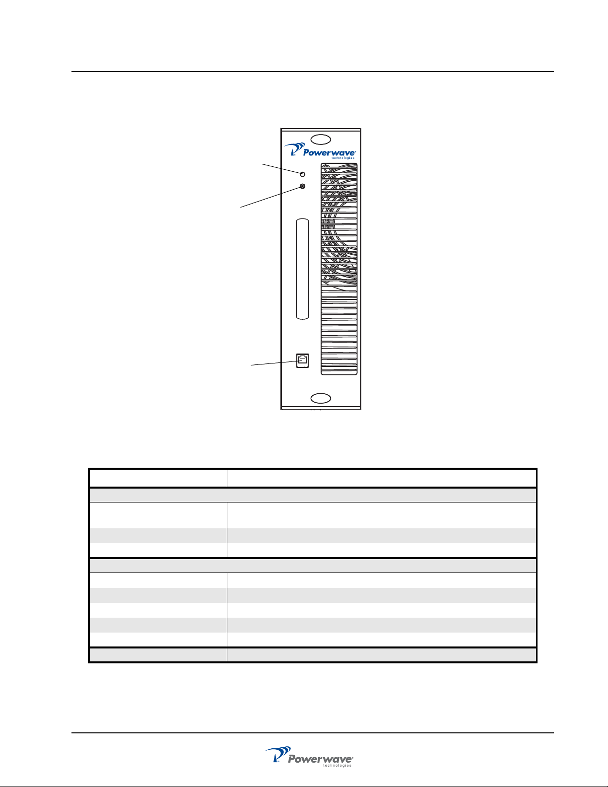
Rectifier
The rectifier module, shown in Figure 3-6, powers up automatically when AC power is applied to the OS. The
dual color LED indicator located at the upper-right side of the front panel displays rectifier status as listed in
Table 3-11.
Figure 3-7 Rectifier Front Panel
Table 3-11 Rectifier Status Indicator
LED Conditions Function
GREEN DC on
AMBER/GREEN Warning
AMBER DC off
3-8 044-05243 Rev A
Page 4
MCPA OS-1933-E3-003
STATUS
RESET
THE POWER IN WIRELESS
TM
PC I/O
ON
OFF
Status
Indicator
RF Switch:
RESET
ON
OFF
PC I/O
RJ-11
Connector
MCPA
MCPA controls and indicators listed in Table 3-12, are located on the MCPA front panel. MCPA operation is
controlled by the OFF/ON/RESET RF toggle switch. MCPA status is displayed by a tri-colored LED.
Table 3-12 MCPA Controls and Indicators
Controls/Indicator Description
Controls (RF)
Toggle Switch - RESET (Up
Momentary)
Toggle Switch - ON (Center) Enables RF
Toggle Switch - OFF (Down) Disables RF
Indicator
Tri-Color LED GREEN (solid) MCPA enabled, no alarm
PC I/O Factory use only
Figure 3-8 MCPA Front Panel
Resets the MCPA
GREEN (blinking) MCPA in standby, no output power
Yellow (solid) Automatic Power Control (APC)
Yellow (blinking) VSWR alarm
Red (solid) MCPA disabled
044-05243 Rev A 3-9
Page 5

OS-1933-E3-003 Controller Web Pages
Controller Web Pages
Figure 3-9 Controller Module
System – Download
Displays the current firmware version and allows firmware related functions. The Controller accommodates two
versions of firmware. The download page will allow the user to toggle between side “A” and side “B” firmware
versions or to download new firmware versions.
Software Download
Downloading a new version of code from the Web Page interface is very easy. It involves selecting only a
couple of options and pressing the “Download Now” button as shown in Figure 3-10. The software will access
the FTP server running on your PC and download the selected file. A CRC check will be performed on the
downloaded file and, if correct, the software will write the downloaded file to flash memory. After the flash
memory write is complete, the software will automatically reset and start executing on the newly downloaded
software.
Follow the steps in Table 3-13 to use the web page for downloading code.
Figure 3-10 Download Web Page
Table 3-13 Downloading Code
Step Action
1 Verify an FTP server is running at the IP address listed on the download page, as shown
2 Place the file to download in the default FTP directory, for example “c:\ftproot”.
3 Select the side to download to, ‘A’ or ‘B’ as shown in Figure 3-10.
4 Press the Browse button and navigate to the FTP download directory as shown in Figure
in Figure 3-10. Usually this is your PC’s IP address.
A free FTP server is “GuildFtpd” and can be downloaded from http://www.guildftpd.com/.
3-11. Select the file to download.
3-10 044-05243 Rev A
Page 6

Controller Web Pages OS-1933-E3-003
Table 3-13 Downloading Code (Continued)
5 Press “Download Now” to start downloading as shown in Figure 3-12. Note that the status
6 Once the download is complete, as shown in Figure 3-14, the Status will indicate
indicates “Download Initialized.” The status will be updated with download progress.
“Successful” and will automatically reset to the side selected for download.
The system will reset and all web pages will have expired. So, when using your browser,
you must re-navigate to the opening web page and log in again.
Figure 3-11 Select File to Download
Figure 3-12 Download Now
044-05243 Rev A 3-11
Page 7

OS-1933-E3-003 Controller Web Pages
Figure 3-13 Download In Progress
Figure 3-14 Download Complete
System – Configuration
This page allows modifications to the system such as Gain adjustment, TMA control, VSWR Alarm threshold,
and Sector and Hardware configurations. All System functions are accessible through this page.
Figure 3-15 System - Configuration page
3-12 044-05243 Rev A
Page 8

Controller Web Pages OS-1933-E3-003
• Installed – Allows sector configuration. Select YES for sectors to be active, choose NO for sectors to
remain vacant. Choose SUBMIT to accept the changes to the page. Initial default is enabled.
• Tx Gain – Allows sector’s TX gain adjustment. Type in the desired gain value in 0.1 dB steps.
Choose SUBMIT to accept the changes to the page. Initially set to 5.0dB.
• LNA Gain - Allows sector’s LNA gain adjustment. Type in the desired gain value in 0.5 dB steps.
Choose SUBMIT to accept the changes to the page. One LNA Gain value per sector applies to the
main and diversity LNA channels. Initially set to 0.0dB.
• TMA Main – Controls the operation of the Main TMAs. Choose ENABLE for TMA use and DISABLE
to suspend TMA use. Choose SUBMIT to accept the changes to the page. Initial default is disabled.
• TMA Diversity – Controls the operation of the Diversity TMAs. Choose ENABLE for TMA use and
DISABLE to suspend TMA use. Choose SUBMIT to accept the changes to the page. Initial default
is disabled.
• VSWR Alarm LL – Allows configuration of the VSWR Alarm threshold. The range is 0.0 to 12.0.
Adjustment does not alter protection shutdown thresholds.
• RECTIFIERS – Controls alarm reporting for each rectifier module (4-total). Configuration does not
effect the operation of the rectifier modules. The rectifier modules are plug n’ play, if they are
inserted with a green LED they are operating. Choose YES for every inserted module to ensure
proper alarm reporting. Choose NO for vacant rectifier slots. Choose SUBMIT to accept the changes
to the page. Initial default is YES. Vacant rectifier slots should be plugged with blank panels to optimize thermal characteristics of the system.
• External Alarms – The system has the capability to detect four form-c inputs. The configuration
allows the each of the four alarms to be configured individually. Choose OFF (default) to disable an
alarm channel. Choose NO (Normally Open) to receive a normally open form-c alarm. Choose NC
(Normally Closed) to receive a normally closed form-c alarm. Received faults will assert a system
Major alarm. Choose SUBMIT to accept the changes to the page.
Status – Static
This page displays the current configuration of the system. The items displayed are not editable and are for
information only.
Figure 3-16 Status - Static page
• Installed – Installed sectors are Yes. Disabled sectors are No.
• Firmware – System and MCPA firmware versions.
• Tx1 Gain – Displays the Tx1 gain setting for each sector.
• Tx2 Gain – Displays the Tx2 gain setting for each sector.
• Tx3 Gain – Displays the Tx3 gain setting for each sector.
• Tx4 Gain – Displays the Tx4 gain setting for each sector.
• LNA Gain – Displays a LNA gain setting for each sector, showing the main and diversity channels.
• TMA Main – Displays the status of each channel.
• TMA Diversity – Displays the status of each channel.
044-05243 Rev A 3-13
Page 9

OS-1933-E3-003 Controller Web Pages
Status – Dynamic
This page displays the current status of the system. The items displayed are not editable and are for
information only.
Figure 3-17 Status - Dynamic page
State
• DEGRADE = Minor system fault Fan / Intrusion / ……
• PASS = Enabled and no faults
• FAIL = Faulted (see the STATUS – ALARM page for details)
• MISSING = Sector is Enabled with missing components, critical sector alarm state.
Temperature – Display of real time temperature sensors for the main system components.
Forward Power – The output power detected at the TX/RX ANT Port for each sector in Watts.
Reverse Power - The reverse power detected at the TX/RX ANT Port for each sector in Watts.
Return Loss – Real-time measurement of the return loss at the TX/RX ANT Port in dB.
TMA Main – Each TMA channels current draw in mA.
TMA Diversity – Each TMA channels current draw in mA.
Alarm Summary – MINOR, MAJOR, CRITICAL status for each sector or system. See the Status – Alarm page
for details
MCPA APC
• OFF — No APC
• ON — APC active and gain display is in accurate and channel is overdriven. Reduce input source or
reduce sector gain.
MCPA Front Panel Switch
• OFF — MCPA disabled via the front panel switch
• ON — MCPA front panel switch is on.
Rectifiers – Installed
• YES — Alarm reporting for this channel is enabled.
• NO — Alarm reporting is disabled for this rectifier channel.
Rectifiers – Comm Status
• Comm — Rectifier module installed, alarm reporting enabled and no faults
3-14 044-05243 Rev A
Page 10

Controller Web Pages OS-1933-E3-003
Rectifiers – Current
The DC current output of each rectifier module. Total DC consumption is the sum of the four rectifiers. Current
sharing technology allows for equal readings for each channel. The DC current is displayed in Amperes.
Rectifiers – Voltage Out –The DC voltage output sensed from each rectifier module. Voltage should be
~28.5Vdc.
Rectifiers – Temperature –The temperature of each rectifier module in degrees Celsius.
Fans – Speed –The RPM display of each of the systems fans. If the system only utilizes 2 fans the FT (front
top) and RT (rear top) positions are active. Maximum RPMs are >4000.
Status – Alarms
This page displays the current detailed alarm status of the system. The items displayed are not editable and
are for information only.
Figure 3-18 Status - Alarms page
The alarms page is organized in a top and bottom section. The top lists on 3 columns the detailed system
alarms related to common system components. The bottom section is divided into the 3 sectors and detail RF
performance issues. A PASS should be displayed for all parameters. A FAIL signifies an issue to be resolved.
This page should be displayed during every maintenance visit.
User
This page allows for modifications to system identification, password and serial number display.
Figure 3-19 User page
044-05243 Rev A 3-15
Page 11

OS-1933-E3-003 Alarm Functions
My ID Number – Entry will assign a unique address to the system. The address is useful for identifying
individual booster cabinets.
Cascade Code – Enter the code required for wireless modem interface.
Serial Number – Display only.
Misc – System Version, display only.
User ID – Change from default “User”.
Password – Change from default “Password”.
Submit – Click to accept all changes.
Alarm Functions
Alarm Status Indicators (front panel)
There are three dual element LEDs displaying the system status. Each LED is mapped to a sector. The LED is
defined by the following chart:
Table 3-14 LED Functions
RATE COLOR PURPOSE
Solid Green Normal
1 Hz Green FW Download
Solid Red Critical Fault / Bypass
Solid Red &
Green
Minor/Major Fault
PC Interface (front panel)
An RS232 interface for testing purposes.
Ethernet Interface (front panel)
Connect Ethernet on controller to Ethernet interface on PC with a crossover RJ45 cable. This port is intended
for local control and monitoring on a temporary basis
3-16 044-05243 Rev A
Page 12

Alarm Functions OS-1933-E3-003
Ethernet Web Page Procedure
Table 3-15 Ethernet Web Procedure
Step Action
1
2
3
4
5
6
7
8
9
10
Connect Ethernet crossover cable from PC to modem front panel ETHERNET connector.
Boot up PC.
On PC, go to Start-Settings-Control Panel Network Connections. Right click on Local Area Connection,
then select Properties.
After Local Area Connection Properties window opens, deselect all functions except Internet Protocol
(TCP/IP).
Double click on Internet Protocol (TCP/IP) to open Internet Protocol (TCP/IP) Properties window.
Select “Use the following IP address”.
At “IP address” type in 192.168.0.2, then press Tab key. Subnet mask fills in 255.255.255.0. Select OK to
close window.
Select OK to close Local Area Connection Properties window.
Open Internet Explorer.
Using Internet Explorer Address bar, type http://192.168.0.1, then press Enter key. The Powerwave
Twoport application is enabled and Log In screen is displayed.
Ethernet Interface (rear panel)
This port is intended for control and monitoring by a BTS or Remote Network Management System on a
permanent basis.
Form-C / External Alarm Interface (rear panel)
Reference the Form-C and External Alarm interface section in chapter 2 for pin-outs and installation.
Form-C Alarms
The alarm status is reported via Form-C contacts. There are five Form-C alarms: ALARM1 through ALARM5.
The alarms are detailed as follows:
Alarm 1
Minor Alarm - all sectors:
• Any cabinet fan fault.
• Intrusion – if one or both booster doors are opened.
• Rectifier Communication Fault.
Alarm 2
A Major Alarm - all sectors:
• TMA1 or TMA2 is faulted (if both enabled), but not both faulted.
• TMA3 or TMA4 is faulted (if both enabled), but not both faulted.
• TMA5 or TMA6 is faulted (if both enabled), but not both faulted.
• LNA1 or LNA2 is faulted, but not both faulted.
• LNA3 or LNA4 is faulted, but not both faulted.
• LNA5 or LNA6 is faulted, but not both faulted.
• Any rectifier fault.
• Any External Alarm fault.
• No communication from the MODEM (if applicable).
044-05243 Rev A 3-17
Page 13

OS-1933-E3-003 Alarm Functions
Alarm 3
A Critical alarm Sector “A” will be asserted if:
• MCPA_A is disabled or vacant.
• All enabled Sector A TMA channels are faulted.
• All Sector A LNA channels are faulted.
• A VSWR fault on Sector A.
• All Rectifiers Faulted.
• RFCU_A removed.
• If the BYPASS_V_A or +5V_EXT_A signals are faulted.
Alarm 4
A critical alarm Sector “B” will be asserted if:
• MCPA_B is disabled or vacant.
• All enabled Sector B TMA channels are faulted.
• All Sector B LNA channels are faulted.
• A VSWR fault on Sector B.
• All Rectifiers Faulted.
• RFCU_B removed.
• If the BYPASS_V_B or +5V_EXT_B signals are faulted.
Alarm 5
A critical alarm Sector “C” will be asserted if:
• MCPA_C is disabled or vacant.
• All enabled Sector C TMA channels are faulted.
• All Sector C LNA channels are faulted.
• All Rectifiers Faulted.
• RFCU_C removed.
• A VSWR fault on Sector C.
• If the BYPASS_V_C or +5V_EXT_C signals are faulted.
External Alarm Inputs
Reference the External Alarm interface section on page 2-7 for pin-outs and installation. Utilize the System/
Configuration page; External Alarms section for configuration options.
3-18 044-05243 Rev A
Page 14

Chapter 4
Maintenance
Introduction
This chapter provides periodic maintenance and removal and replacement procedures for the OS-1933-E0003 Outdoor MCPA System.
Periodic Maintenance
Suggested periodic maintenance requirements are listed in Table 4-1.
WARNING: Wear proper eye protection to avoid eye injury when using compressed air.
CAUTION: Use only dry compressed air when cleaning the OS, do not use pressure washers.
To ensure proper cooling and prevent MCPA over temperature shutdown, one of the two booster doors
must be closed and secure at all times.
NOTE: Do not break the seals on equipment under warranty or the warranty will be null and void. Do not
return equipment for warranty or repair service until proper shipping instructions are received from the factory.
Table 4-1 Periodic Maintenance
Task Interval Action
Cleaning:
Filters 12 months Inspect and clean air filters.
Air Vents
Inspection:
Cables and
Connectors
During periodic
site maintenance
During periodic
site maintenance
Inspect and clean inlet and outlet air vents. If equipment is
operated in a dusty or industrial environment, inlets and outlets
should be inspected more often.
Inspect signal and power cables for frayed insulation. Check RF
connectors to ensure tightness.
Cleaning Air Inlets/Outlets/Filter
The air inlets and outlets should be cleaned during periodic site maintenance. If the equipment is operated in a
heavy industrial or severe dust environment, the inlets and outlets should be cleaned as necessary. Cooling
efficiency can be reduced if dust and dirt are allowed to accumulate. Remove the panel and, using either
compressed air or a brush with soft bristles, loosen and remove accumulated dust and dirt from the air inlet
and outlet panels. Replace the panel when cleaned.
The air filters, located in the front and rear panels, also must be removed and cleaned using compressed air.
Refer to Air Filter Cleaning, page 4-10,Table 4-9, Figure 4-6 for filter cleaning and replacement instructions.
044-05243 Rev A 4-1
Page 15

OS-1933-E3-003 Troubleshooting
Troubleshooting
Status of each individual module can be determined by the status of the LED (MCPAs, Rectifier, Controller
represents system and RFCUs). All LEDs should illuminate a solid green; any other indication requires access
to the Status / Alarm page. Some common alarms and there remedies are detailed in the following sections.
MCPA does not have a solid green LED
Table 4-2 MCPA - no solid green LED
LED Color Status Action
Red Solid
No LED No LED
Yellow Blinking
Yellow Solid
Red/Yellow Blinking
Open Status / Alarms page for details about the MCPA fault.
Check Power system or verify the appropriate fuse located on the
rear of the power system.
The MCPA is measuring >50W of reflected power.
i. Ensure that the TX/RX ANT ports are terminated adequately
ii. Ensure that the MCPA is installed fully and the latches are
secured.
iii. Try reseating the MCPA; disable the MCPA by the front panel
switch (down) before removing.
iv.If not remedied the MCPA will shutdown in one minute. If shutdown
for VSWR, the MCPA will require a manual reset with the front panel
switch (up position) to recover.
The MCPA has reduced gain to compensate for an excessive input
level.
i. Ensure the input sources are within the specified power levels.
ii. Ensure the TX Gain is configured in accordance to the
specifications in Section 5.
iii. The MCPA can only compensate for 6dB. The MCPA could
disable and require a manual reset via the front panel switch (up
position).
iv. Operating the OS System equipment under this condition could
manifest into a system shutdown due to excessive temperature and/
or RF power.
Firmware is not loading correctly
i. Extract module from the OS system
ii. Place the front panel switch in the ON position (middle)
iii. Re-insert the MCPA into the OS system
iv. Latch to top and bottom fasteners.
The MCPA is ready to enable, but something in the system is
preventing this. Check the following
i. Verify the Sector is enabled via the System/Configuration page,
Installed section.
ii. Attempt re-seating the MCPA and ensuring the latches are locked.
iii. Try another MCPA.
Green Blinking
iv. View the Status/Alarm page for more details
v. If the communication to the system cannot be established the
controller is not operating. Cycle the AC source to restart the system.
vi. Ensure DC power is getting to the controller; check the fuse on the
rear of the power system. Measure the +28.5Vdc on the controller
JX.
vii. Replace controller. See page 4-7.
4-2 044-05243 Rev A
Page 16

Troubleshooting OS-1933-E3-003
Rectifier Module with a Red LED or Individual Faults
– Any rectifier module fault is remedied by replacing a known good module with the suspected unit. Refer to
the Status/Alarm page for exact details. Reference the Rectifier Module section in Chapter 2 for the procedure
on Rectifier Module replacement.
RECT ALL COMM Fault
Could to the result of a bad RJ45 interface cable at the rear of the system linking the controller with the power
system. A non-crossover network cable could be temporarily installed to validate the connection.
Rectifier Voltage Fault
Measure the AC input and/or DC Output (all 4 fused outputs) and validate that the voltage is within the
specified range detailed in section 5.
Fans Not Operating –
• Check the status of the fans on the Status/Dynamic page.
• The fan of a specific door will not operate if that door is not secured. Ensure that the front and rear
doors are secured and that both fans are operating any time there is a site visit.
• The fan circuitry has an auto-resettable fuse. Unplugging a bad fan and installing a known good fan
should reset the fuse. The intrusion plunger must be pulled to the out position to simulate a door closure and allow the fan to operate.
• The OS System components are not >41 C. Fans do not operate below this threshold.
RFCU Alarms
Status/Alarm Page Faults – Bypass V, 5V, LNA Alarm 1/2 could be an indication of a bad RFCU. Replace the
RFCU module per the procedure in the RFCU section of Chapter 2.
RF Performance Issues -
• No power out or gain:
• View the Status/Alarm page correct all detected alarms
• Disable the MCPA to force the sector into bypass, using external measuring equipment validate the
RF passing through the OS System.
• Disable the MCPA first then reseat the MCPA and RFCU modules, enable the MCPA
• Replace the MCPA and/or RFCU with a known good module.
044-05243 Rev A 4-3
 Loading...