


G3L-1929-160-001
Multi-Carrier
Power Amplifier
Installation and
Service Manual
044-05305 Rev A
August 2007

© 2007 Powerwave Technologies Incorporated. All rights reserved.
Powerwave Technologies, and the Powerwave logo are registered trademarks.
This Powerwave product is intended only for installation in a RESTRICTED ACCESS LOCATION and
this Powerwave product is designed to operate within the normal operating (typical operating) ranges
or conditions specified in this document. Operation of this equipment beyond the specified ranges in
this document may cause:
1. Spurious emissions that violate regulatory requirements.
2. The equipment to be automatically removed from service when maximum thresholds are exceeded.
3. The equipment to not perform in accordance with its specifications.
It is the operator’s responsibility of the operator to ensure this equipment is properly installed and
operated within Powerwave operating specifications to obtain proper performance from the equipment
and to comply with regulatory requirements.
For PERMANENTLY CONNECTED EQUIPMENT, a readily accessible disconnect device shall be
incorporated in the building permanent wiring.

Warnings, Cautions, and Notes
Warnings, Cautions, and Notes are found throughout this manual where applicable. The associated
icons are used to quickly identify a potential condition that could result in the consequences described
below if precautions are not taken. Notes clarify and provide additional information to assist the user.
WARNING: This warning symbol means danger. You are in a situation that could cause
bodily injury or death. Before working on any equipment, be aware of the hazards involved
with electrical and RF circuits and be familiar with standard practices for preventing accidents.
CAUTION: The caution symbol means reader be careful. In this situation, the user might do
something that could result in equipment damage or loss of data.
NOTE
The note symbol means reader take note. Notes contain helpful suggestions or references
to material not covered in this document. Procedures are not contained in notes.
044-05305 Rev A i

Revision Record
Revision Letter Date of Change Reason for Change
A Aug 2007 Initial Release
ii 044-05305 Rev A

Table of Contents
Chapter 1 - Product Description
Introduction . . . . . . . . . . . . . . . . . . . . . . . . . . . . . . . . . . . . . . . . . . . . . . . . . . . . . . . . . . . . . . . . . . . . . . . . . . .1-1
Scope of Manual . . . . . . . . . . . . . . . . . . . . . . . . . . . . . . . . . . . . . . . . . . . . . . . . . . . . . . . . . . . . . . . . . . . . . . .1-1
Product Description . . . . . . . . . . . . . . . . . . . . . . . . . . . . . . . . . . . . . . . . . . . . . . . . . . . . . . . . . . . . . . . . . . . . .1-1
Functional Description . . . . . . . . . . . . . . . . . . . . . . . . . . . . . . . . . . . . . . . . . . . . . . . . . . . . . . . . . . . . . . . . . . .1-1
Chapter 2 - Controls and Indicators
Introduction . . . . . . . . . . . . . . . . . . . . . . . . . . . . . . . . . . . . . . . . . . . . . . . . . . . . . . . . . . . . . . . . . . . . . . . . . . .2-1
MCPA Controls and Indicators . . . . . . . . . . . . . . . . . . . . . . . . . . . . . . . . . . . . . . . . . . . . . . . . . . . . . . . . . . . .2-1
Chapter 3 - Installation
Introduction . . . . . . . . . . . . . . . . . . . . . . . . . . . . . . . . . . . . . . . . . . . . . . . . . . . . . . . . . . . . . . . . . . . . . . . . . . .3-1
Unpacking and Inspection . . . . . . . . . . . . . . . . . . . . . . . . . . . . . . . . . . . . . . . . . . . . . . . . . . . . . . . . . . . . . . . .3-1
Damaged Equipment. . . . . . . . . . . . . . . . . . . . . . . . . . . . . . . . . . . . . . . . . . . . . . . . . . . . . . . . . . . . . . . . . . . . 3-1
Air Conditioning Requirement . . . . . . . . . . . . . . . . . . . . . . . . . . . . . . . . . . . . . . . . . . . . . . . . . . . . . . . . . . . . .3-1
MCPA Installation Instructions. . . . . . . . . . . . . . . . . . . . . . . . . . . . . . . . . . . . . . . . . . . . . . . . . . . . . . . . . . . . . 3-1
Initial Start-up and Operating Procedures . . . . . . . . . . . . . . . . . . . . . . . . . . . . . . . . . . . . . . . . . . . . . . . . . . . . 3-3
Chapter 4 - Maintenance
Introduction . . . . . . . . . . . . . . . . . . . . . . . . . . . . . . . . . . . . . . . . . . . . . . . . . . . . . . . . . . . . . . . . . . . . . . . . . . .4-1
Periodic Maintenance . . . . . . . . . . . . . . . . . . . . . . . . . . . . . . . . . . . . . . . . . . . . . . . . . . . . . . . . . . . . . . . . . . .4-1
Troubleshooting. . . . . . . . . . . . . . . . . . . . . . . . . . . . . . . . . . . . . . . . . . . . . . . . . . . . . . . . . . . . . . . . . . . . . . . . 4-1
MCPA Removal and Replacement . . . . . . . . . . . . . . . . . . . . . . . . . . . . . . . . . . . . . . . . . . . . . . . . . . . . . . . . .4-2
Return for Service Procedures . . . . . . . . . . . . . . . . . . . . . . . . . . . . . . . . . . . . . . . . . . . . . . . . . . . . . . . . . . . .4-2
Obtaining an RMA. . . . . . . . . . . . . . . . . . . . . . . . . . . . . . . . . . . . . . . . . . . . . . . . . . . . . . . . . . . . . . . . . . . 4-2
Repackaging for Shipment . . . . . . . . . . . . . . . . . . . . . . . . . . . . . . . . . . . . . . . . . . . . . . . . . . . . . . . . . . . . 4-2
Chapter 5 - Specifications
Multi-Carrier Power Amplifier Specifications . . . . . . . . . . . . . . . . . . . . . . . . . . . . . . . . . . . . . . . . . . . . . . . . . .5-1
044-05305 Rev A iii

Table of Contents G3L-1929-160-001
List of Figures
1-1 MCPA Front and Rear Views . . . . . . . . . . . . . . . . . . . . . . . . . . . . . . . . . . . . . . . . . . . . . . . . . . . . . . . . 1-2
1-2 MCPA Functional Block Diagram . . . . . . . . . . . . . . . . . . . . . . . . . . . . . . . . . . . . . . . . . . . . . . . . . . . . . . 1-3
2-1 MCPA Controls and Indicators . . . . . . . . . . . . . . . . . . . . . . . . . . . . . . . . . . . . . . . . . . . . . . . . . . . . . . . 2-1
2-2 MCPA Interface Connector . . . . . . . . . . . . . . . . . . . . . . . . . . . . . . . . . . . . . . . . . . . . . . . . . . . . . . . . . . 2-3
3-1 MCPA Quarter-Turn Fasteners and Connectors . . . . . . . . . . . . . . . . . . . . . . . . . . . . . . . . . . . . . . . . . . 3-2
List of Tables
2-1 MCPA Controls and Indicators . . . . . . . . . . . . . . . . . . . . . . . . . . . . . . . . . . . . . . . . . . . . . . . . . . . . . . . 2-2
2-2 MCPA Alarm States . . . . . . . . . . . . . . . . . . . . . . . . . . . . . . . . . . . . . . . . . . . . . . . . . . . . . . . . . . . . . . . 2-2
2-3 MCPA Connector Pinouts . . . . . . . . . . . . . . . . . . . . . . . . . . . . . . . . . . . . . . . . . . . . . . . . . . . . . . . . . . . 2-4
3-1 MCPA Unpacking and Inspection Instructions . . . . . . . . . . . . . . . . . . . . . . . . . . . . . . . . . . . . . . . . . . . 3-1
3-2 MCPA Installation . . . . . . . . . . . . . . . . . . . . . . . . . . . . . . . . . . . . . . . . . . . . . . . . . . . . . . . . . . . . . . . . . 3-2
3-3 Initial Start-up Procedure . . . . . . . . . . . . . . . . . . . . . . . . . . . . . . . . . . . . . . . . . . . . . . . . . . . . . . . . . . . . 3-3
4-1 Recommended Periodic Maintenance . . . . . . . . . . . . . . . . . . . . . . . . . . . . . . . . . . . . . . . . . . . . . . . . . 4-1
4-2 Troubleshooting . . . . . . . . . . . . . . . . . . . . . . . . . . . . . . . . . . . . . . . . . . . . . . . . . . . . . . . . . . . . . . . . . . 4-1
4-3 MCPA Removal and Replacement . . . . . . . . . . . . . . . . . . . . . . . . . . . . . . . . . . . . . . . . . . . . . . . . . . . . 4-2
5-1 MCPA Specifications . . . . . . . . . . . . . . . . . . . . . . . . . . . . . . . . . . . . . . . . . . . . . . . . . . . . . . . . . . . . . . . 5-1
iv 044-05305 Rev A

Chapter 1
Product Description
Introduction
This manual contains information and procedures for the installation, operation, and maintenance of the
G3L-1929-160-001 Multi-Carrier Power Amplifier (MCPA).
Scope of Manual
This manual is intended for use by service technicians familiar with similar types of equipment. It contains
service information required for the equipment described and is current as of the printing date. Changes which
occur after the printing date may be incorporated by a complete manual revision or alternatively as additions.
The manual is organized into the following chapters:
❑ Chapter 1 - Product Description
❑ Chapter 2 - Controls and Indicators
❑ Chapter 3 - Installation
❑ Chapter 4 - Maintenance
❑ Chapter 5 - Specifications
Product Description
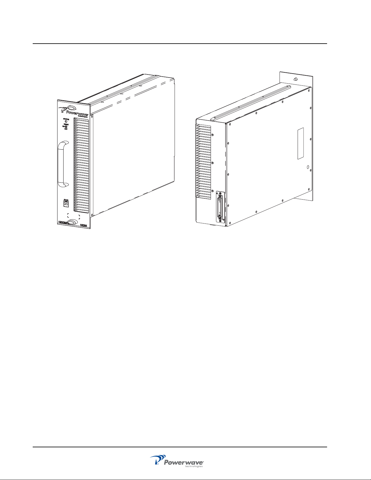
The MCPA shown in Figure 1-1 MCPA Front and Rear Views is a linear, feed-forward multi-carrier power
amplifier that operates in the PCS band from 1930 MHz to 1995 MHz with an instantaneous bandwidth of
65 MHz. The instantaneous bandwidth is the maximum frequency band in which any two or more signals can
occupy. The instantaneous bandwidth of the MCPA is set automatically.
The MCPA is modular in design and ideally suited for use in CDMA 2000, CDMA and and 1X-EVDO base
stations. The MCPA provides a gain of 63 dB to supply a 160 watt output. Refer to Figure 1-2 MCPA
Functional Block Diagram for the MCPA functional block diagram. Refer to Chapter 5 for the MCPA
specifications.
Functional Description
The MCPA is a self-contained module typically operated in parallel with other identical MCPAs as part of a
subrack assembly.
The MCPA consists of the following major functions:
❑ Preamplifier
❑ Main and error amplifiers
❑ Feed-forward loop control
❑ Pilot tone generator
❑ Controller
❑ Cooling
❑ Power Distribution
044-05305 Rev A 1-1
Functional Description G3L-1929-160-001 MCPA
Front
Rear
Figure 1-1 MCPA Front and Rear Views
1-2 044-05305 Rev A
 Loading...