


LinkNet™ LNKF100
RF MODULES
User, Installation, Operation,
and Maintenance Manual
D044-13432 Rev A
December 2005

© 2005 Powerwave Technologies Incorporated. All rights reserved.
Powerwave Technologies, and the Powerwave logo are registered trademarks.
This Powerwave product is intended only for installation in a RESTRICTED
ACCESS LOCATION and is designed to operate within the Normal Operating
(typical operating) ranges or conditions specified in this document. Operation of
this equipment beyond the specified ranges in this document may cause:
1. Spurious emissions that violate regulatory requirements.
2. The equipment to be automatically removed from service when maximum
thresholds are exceeded.
3. The equipment to not perform in accordance with its specifications.
It is the Operator's responsibility to ensure this equipment is properly installed and
operated within Powerwave operating specifications to obtain proper performance from
the equipment and to comply with regulatory requirements.
Warnings, Cautions, and Notes
Warnings, Cautions, and Notes
Warnings, cautions, and notes are found throughout this manual where applicab le. The
associated icons are used to quickly identify a potential condition that could result in the
consequences described below if precautions are not taken. Notes clarify and provide additional
information to assist the user.
Warning
This warning symbol means danger. You are in a situation that could
cause bodily injury. Before you work on any equipment, be aware of the
hazards involved with electrical and RF circuitry and be familiar with
standard practices for preventing accidents.
Caution This caution symbol means reader be careful. In this situation, the user
might do something that could result in equipment damage or loss of
data.
Note This note symbol means reader take note. Notes contain helpful
suggestions or references to material not covered in the document.
Procedures are not contained in notes.
D044-13432 Rev A i

Revision Record
Revision Record
Revision Letter Date of Change Reason for Change
A Dec 2005 Initial Release
ii D044-13432 Rev A

TABLE OF CONTENTS
Chapter 1 .............................................................................................................1
Theory of Operation............................................................................................1
1 Introduction................................................................................................1
1.1 OVERVIEW.......................................................................................................................... 1
1.2 MODELS ............................................................................................................................. 1
1.3 BLOCK DIAGRAM ................................................................................................................ 2
1.4 MODULE SPECIFICATIONS.................................................................................................... 3
ALSO CONSULT THE MAIN LINKNET™ MANUAL DCM000000008. .................................................... 3
Chapter 2 .............................................................................................................5
Operation.............................................................................................................5
2 Introduction................................................................................................5
2.1 SOFTWARE SET-UP............................................................................................................. 5
2.2 CONFIGURATION ................................................................................................................. 5
2.3 POWER ON SELF TEST (POST)........................................................................................... 6
2.4 FAULT INDICATIONS............................................................................................................. 6
2.5 NORMAL OPERATION........................................................................................................... 7
2.6 SIMPLEX OPERATION........................................................................................................... 8
Chapter 3 .............................................................................................................9
Antenna Installation............................................................................................9
3 Introduction................................................................................................9
3.1 ANTENNA INSTALLATION ..................................................................................................... 9
3.2 FCC INFORMATION TO USERS ........................................................................................... 10
Chapter 4 ...........................................................................................................11
Return for Service.............................................................................................11
4 Introduction..............................................................................................11
4.1 RETURN FOR SERVICE PROCEDURE................................................................................... 11
4.1.1 Obtaining An RMA................................................................................................. 11
4.1.2 Repackaging For Shipment.................................................................................. 11
4.2 PARTS AND ACCESSORIES................................................................................................. 11
D044-13432 Rev A iii

Table of Figures
TABLE OF FIGURES
Figure 1-1 Block Diagram LNK100 RF Module........................................................................... 2
Figure 2-1 LNKF100 Faceplate..................................................................................................... 7
Figure 2-2 LNKF100 Simplex Interconnection............................................................................ 8
Figure 2-3 LNKF100 RF Connection............................................................................................ 8
TABLE OF TABLES
Table 1 LNKF100 Module Family.................................................................................................. 1
Table 2 LNKF100 Module Specifications .................................................................................... 3
Table 3 LNKF100 Factory Set Options........................................................................................ 5
iv D044-13432 Rev A

Chapter 1
Theory of Operation
1 Introduction
This manual contains information and procedures for installation, operation, maintenance, and
troubleshooting of the LNKF100 Modules. The manual is organized into the following chapters:
Chapter 1 Theory of Operation Chapter 3 Antenna Installation
Chapter 2 Operation Chapter 4 Return for Service
1.1 Overview
A LinkNet FM Module is a radio repeater that simulta neously receive s and transmits a single narro w
band radio channel. The normal application of a L inkNet FM Modul e is as an on -frequency repeater
where the input and output are on exactly the same frequency. It can also be used as a fre quency
translating repeater where the input and output can be set to any frequency i n the specified b and (see
Table 1 for details).
The LinkNet FM Module accomplishes its repeater functi on without stor e and forward circuit ry, or
expensive conventional simulcasting techniques. T he fact that the sa me frequency can be
retransmitted by a LinkNet FM Module means that additiona l frequency allocation s are not required in
situations where an existing radio coverage pattern ne eds to be extended. T he most common Li nkNet
FM Module applications are the extension of above ground signals into buil dings, tunnels, veh icles or
the extension of radio coverage patterns into outdoor shade d areas such as deep valleys.
From an applications standpoint, a LinkNet FM Module is very similar to a regular two-way radio
repeater. LinkNet FM Modules can be combined using regul ar two-way radio multi coupling or
duplexing equipment and have input and output sig nal characteristic s to those of regular t ransmitters
and receivers. The one special consideration in LinkNet FM Module systems is that of input to out put
antenna isolation. This must be carefully en gineered for e ach installation.
LinkNet FM Modules are designed for indoor use only and are intended for mounting in a standard EIA
19 inch rack. The Modular design of LinkNet FM Mod ule circuitry allows for e asy servicing, stoc king of
spares, adaptability and upgrade ability.
1.2 Models
Table 1 LNKF100 Module Family
LNKF100 MODULE FAMILY
MODEL TYPE FREQUENCY
LNKF100-A1 25 KHz FM Channels 136-157 MHz (FM)
LNKF100-A2 12.5 KHz FM Channels 136-157 MHz (FM)
LNKF100-B1 25 KHz FM Channels 155-174 MHz (FM)
LNKF100-B2 12.5 KHz FM Channels 155-174 MHz (FM)
D044-13432 Rev A 1

Block Diagram
1.3 Block Diagram
LNKF100 RF Module:
Figure 1-1 Block Diagram LNK100 RF Module
2 D044-13432 Rev A

Module Specifications
1.4 Module Specifications
Table 2 LNKF100 Module Specifications
Frequency Bands See Model Chart
Modulation & Channel Spacing
RF Frequency Stability Tracks Input Signal Exactly
Max. RF Output Power 37 dBm
RF Output Power Range +20dBm to +37dBm
RF Output Power Variation vs. Input
(over -90 to -30 dBm)
Input Dynamic Range -110 to -30 dBm
Input Sensitivity Adjust Range -110 to -50 dBm
Input Hysteresis 1 to 10 dB
Adjacent Channel Selectivity
Transmit Duty Cycle Continuous
Transmit Spurious
Receive Conducted Spurious -57 dBm max
Audio Distortion & Noise
Transmit Key-Up & Key-Down Times <2 mS Key-Up, <1 mS Key-Down
Group Delay
RF Connectors
Module Power Supply Requirements 45 Watts maximum
Connections
Front Panel Indicators
Configuration Options
Operating Temperature Range
Operating Humidity Range 10 to 90% RH, Non-Condensing
Size & Weight
FCC Identifier
Industry Canada Certification
25 or 12.5 KHz as per Model Chart
60 dB minimum for 25 KHz modules
55 dB minimum for 12.5 KHz modules
-13 dBm max for 25 KHz modules
-20 dBm max for 12.5 KHz modules
<4% increase for 25 KHz modules
<5% increase for 12.5 KHz modules
Edge Connector & 2 SMA RF Connectors, DB-15
Connector on back of Card-Cage provides per-
Module Fault Relay, Interconnect to other
Operating, Stand by, Fault, Program Mode,
RF Modules may be configured either via the
optional Gateway Module, or via a PC and an RS-
232 Connection via the Card-Cage.
-10 to +50
9.11” High, 2.00” Wide, 14.00” Deep,
Narrowband FM
+/- 1 dB
<120 usec for 25 KHz,
<160 usec for 12.5 KHz
SMA (50Ω) Connectors
Modules, & RS-232 Connection
Receive, Transmit
o
C; consult manual DCM000000008 for
cooling requirements
10 lbs, 4.5 kg Max
Also consult the main LinkNet™ Manual DCM000000008.
D044-13432 Rev A 3

(This page intentionally left blank)
4 D044-13432 Rev A

Chapter 2
Operation
2 Introduction
This chapter contains information for the standard operation of the LNKF100 Modules.
2.1 Software Set-Up
The LNKF100 module is shipped with the following factory set options:
Table 3 LNKF100 Factory Set Options
OPTION RANGE OF VALUES DEFAULT VALUE
Frequency See Model Chart Order Specific
Receive Threshold
Receive Hysteresis 1 to 10 dB 3.0 dB
Time Out 1 to 600 Seconds, or none None
Module Enabled On / Off On
Transmit Power Level 20 to 37 dBm Order Specific
Default values may be changed when an order is placed. Check your orde r confirmation (shipped
with modules) for customized values.
2.2 Configuration
In line with the versatility of the LinkNetTM Platform, it is possible to reconfigure the LNKF100
module in the field, either with a Personal Computer (PC) or via the optional Control Module. To
use a PC it is necessary to have a Powerwave CAB000000057 control cable to connect between
the appropriate module's DB15 connector on the back of the card-cage and the standard DB9
RS232 connector on the PC. On the PC a terminal emulation program such as HyperTerminal is
used to communicate to the LinkNet Module. The settings are 9600 baud, 8 bits, no parity, and 1
stop bit. Commands are one or two words followed by pressing Return. Commands may be given
in upper or lower-case. Available commands are:
–110 to -50 dB -95 dB
ACCESS USER: Required as a simple password to gain access to customer settable
parameters and diagnostics. This will time-out after 10 minutes, and may
have to be re-typed.
HELP or ?: Displays a list of available commands.
LIST: Displays current settings and status faults, etc.
VER: Display the current version of software.
ENABLE 1 or 0: Enables or disables the module.
TXFREQ #########: Displays or sets the current transmit frequency (in Hertz).
RXFREQ #########: Displays or sets the current receive frequency (in Hertz).
TXPOWER ###: Displays or sets the transmit power level (in tenths of a dBm).
RXTHRESH -####: Displays or sets the receive threshold level (in tenths of a dBm).
RXHYSTER ##: Displays or sets the receive hysteresis (in tenths of a dB).
TIMEOUT ####: Displays or sets the timeout-timer value (in Seconds).
Enter 0 for no timeout.
TESTOSC 1 or 0: Enables or disables the test oscillator.
Please consult Powerwave Technologies Inc. for further support.
D044-13432 Rev A 5

Power On Self Test (POST)
2.3 Power On Self Test (POST)
Each module automatically performs a self-diagno stics when inserte d into the syste m card-cage.
These tests determine that the unit is correctly installed in the card-cage an d not damaged in t ransit.
•
All six of the LED’s on the front panel will flash 3 times
•
If the LED’s do NOT flash three times, then remove the module, check the power source, and
re-insert the module, (See Installation Instructions).
If the card is “OK” the LED’s will continue normally (See Normal Operation).
•
•
If there is a fault, then the Red Fault LED will remain on. If this occurs, contact Powerwave
Technologies Inc.
Note! The Power On Self Test is Not an RF test, it only verifies that there is power to the unit and
that the logical circuitry is functioning.
2.4 Fault Indications
Each module continuously performs internal diagnostics. If a problem is detected it will activate its Red
Fault LED and Fault Relay. Faults detected include:
•
Over Temperature
•
High VSWR
•
Loss of Lock
•
Misc. Internal Faults
Detailed faults are detected by the optional gateway module. Details may also be determined via
the module's control port connector and an RS232 connected Terminal Emulator using the LIST
command.
6 D044-13432 Rev A

Normal Operation
2.5 Normal Operation
The LNKF100 Module has six LED’s o n the faceplate:
OPERATING - LED will flash GREEN when RF Data is present and unit
is operating normally.
STANDBY – Under the control of the Control Module, the LNKF100
Module has the ability to act as a duplex transmitter, sitting perpetually in
stand by mode waiting for the primary transmitter to fail. This LED should
be constant Amber. If a fault should occur with the primary mo dule, the
“Stand by” unit will immediately become the primary unit, at which time
the stand by LED will be turned off and the LED’s will show an operating
module.
TRANSMIT – Green when a signal is being tran smitted.
RECEIVE – Green when a signal is being received.
PROGRAM – Constant Amber when the unit is being re-programmed by
the controller module. This will signify that the unit is powered on but
unavailable for use.
FAULT – Constant Red if the internal diagnostics for the module detect s a
problem.
Figure 2-1 LNKF100 Faceplate
D044-13432 Rev A 7
Simplex Operation
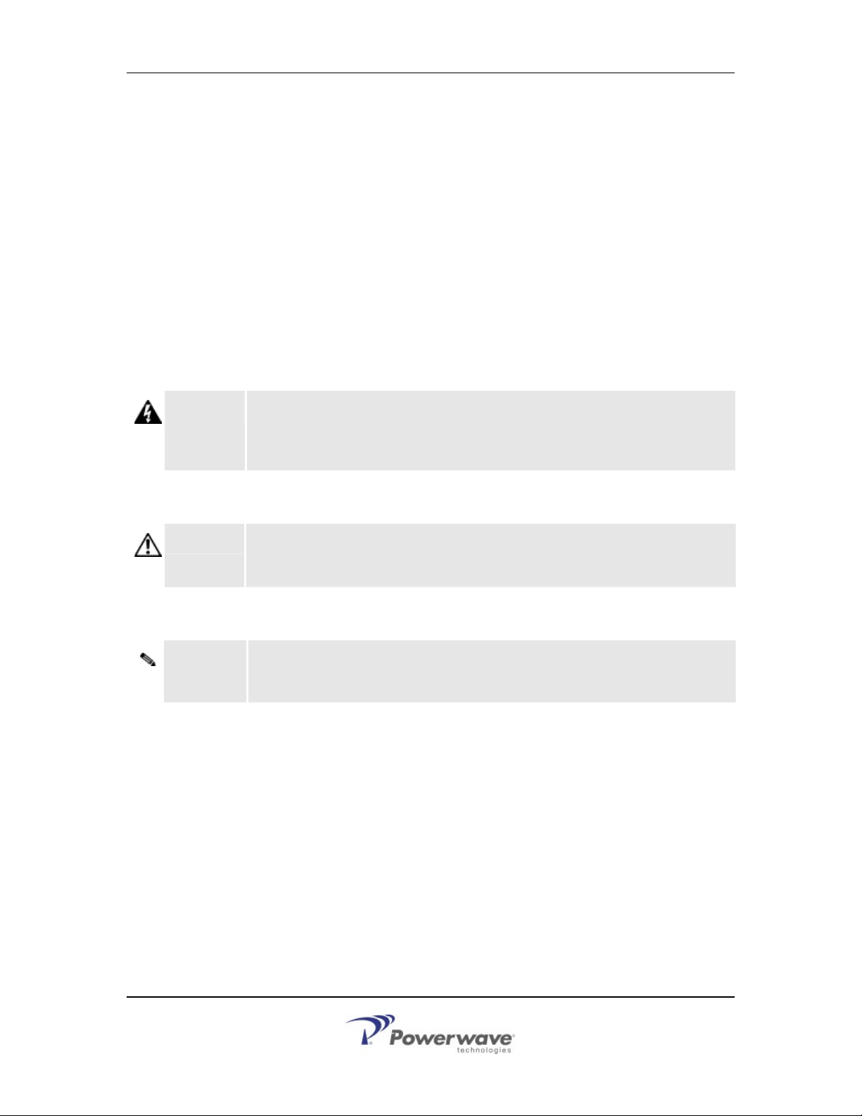
2.6 Simplex Operation
For back-to-back Simplex operation, the LinkNet Modules to be used MUST be interconnected
•
as shown:
Figure 2-2 LNKF100 Simplex Interconnection
•
This connecti on is made using a custom male DB15 to male DB15 cable as shown above
interconnected between the two LNKF modules. This cable is plugged into the two modul e's
control ports (see DCM000000008 "Control Connections") on the back of the chassis they are
installed in.
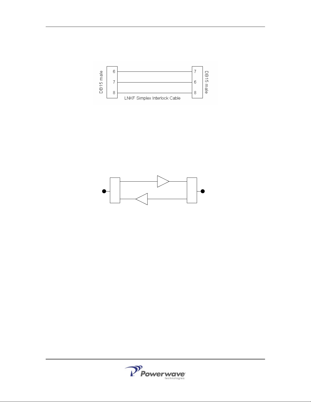
The RF connections are made using either combiners or RF Relays:
•
DOWNLINK LNKF MODULE
DONOR
UPLINK LNKF MODULE
COMBINERS OR
RF RELAYS
Figure 2-3 LNKF100 RF Connection
COMBINERS OR
RF RELAYS
DISTRIBUTION
• The specific details are determined by the system design, and must provide enough RF
isolation between the two modules.
8 D044-13432 Rev A

Chapter 3
Antenna Installation
3 Introduction
This chapter contains antenna installation and warning information for the LNKF100 Mod ules.
3.1 Antenna Installation
All antenna installation to be performed by qualified technical personnel only.
•
Antenna installation instructions and locations below are for the purpose of satisfying
•
FCC RF Exposure Compliance requirements.
Note! If multiple LinkNet™ Modules are used, the Instructions below apply to the
composite power output of all Modules when transmitting simultaneously.
The Roof Top Antenna or Antennae for linking to the Donor Site(s) is/are directional (high
•
gain) Antennae, fixed-mounted physically on the side or top of a building, or on a tower.
The Antenna Gain must be no more than 20 dBi.
Note! If multiple LinkNet™ Modules are used with output combiners into any one
Antenna, and/or multiple Antennae are used on one Roof Top, then the sum of
composite powers into all Roof Top Antennae must not exceed 20 Watts maximum.
The Roof Top Antennae location should be such that only qualified technical person nel
•
can access it, and that under normal operating conditions no other person can touch the
antenna, or approach within 10 meters of the antenna.
The In-Building Antenna connection is via a coaxial cable distribution system with signal
•
taps at various points connected to the fixed-mounted Indoor Antennae. The Indoor
Antennae are simple 1/4 wavelength (0 dB Gain) types. They are used with Powerwave
Technologies’ 12, 16, or 20 dB cable taps. As such the maximum EIRP will be at the first
tapped antenna, which will be 12 dB below the maximum signal level of the LinkNet™
(+40 dBm); +28 dBm, or 0.63 Watts EIRP. These antennae are to be installed such that
no person can touch the antenna, or approach within 0.2 Meters.
Note! If multiple LinkNet™ Modules are used with output combiners, then the composite
power output of all Modules transmitting simultaneously must meet this maximum
EIRP requirement.
Please consult Powerwave Technologies Inc. for assistance as required.
D044-13432 Rev A 9

FCC Information to Users
ANTENNA INSTALLATION
CAUTION
ALL ANTENNA INSTALLATION IS TO BE PERFORMED BY QUALIFIED TECHNICAL
PERSONNEL ONLY.
ANTENNA INSTALLATION INSTRUCTIONS AND LOCATIONS ARE FOR THE PURPOSE
OF SATISFYING FCC RF EXPOSURE COMPLIANCE REQUIREMENTS, AND ARE NOT
OPTIONAL.
ALL ROOF TOP ANTENNA INSTALLATION MUST BE SUCH THAT NO PERSON CAN
TOUCH THE ANTENNA, OR APPROACH CLOSER THAN 10 METERS.
ALL IN-BUILDING ANTENNAE INSTALLATIONS MUST BE SUCH THAT NO PERSON CAN
TOUCH THE ANTENNAE, OR APPROACH CLOSER THAN 0.2 METERS.
3.2 FCC Information to Users
This equipment has been tested and found to comply with the limits for a Class A
•
digital device, pursuant to Part 15 of the FCC Rules. These limits are designed to
provide reasonable protection against harmful interference when the equipment is
operated in a commercial environment. This equipment generates, uses, and can
radiate radio frequency energy and, if not installed and used in accordance with the
instruction manual, may cause harmful interference to radio communications.
Operation of this equipment in a residential area is likely to cause harmful
interference in which case the user will be required to correct the interference at his
own expense.
CHANGES OR MODIFICATIONS NOT EXPRESSLY APPROVED BY POWERWAVE
TECHNOLOGIES INC. COULD VOID THE USER’S AUTHORITY TO OPERATE THE
EQUIPMENT.
CAUTION
10 D044-13432 Rev A

Chapter 4
Return for Service
4 Introduction
This chapter contains return for servi ce and part s and accesso ries information fo r the LNKF100
Modules.
4.1 Return For Service Procedure
When returning products to Powerwave Technologies Inc., the following procedures will ensure
optimum response.
4.1.1 Obtaining An RMA
A Return Material Authorization (RMA) number must be obtained prio r to returning eq uipment to the
factor for service. Please contact our Repair Department at +1 (714) 466-1000 to obtain this number, or
FAX your request to +1 (714) 466-5816 or
number may result in delays in receiving repair service.
mailto:RMA@PWAV.COM. Failure to obtain this RMA
4.1.2 Repackaging For Shipment
To ensure safe shipment of the amplifier, it is recomme nded that the or iginal package de signed for
shipping the amplifier be reused. If it is not availabl e, contact Powerwav e Technologies Inc. Cu stomer
Service Department for packing materials.
4.2 Parts and Accessories
Parts and Accessories for the LNKF100 Modules may be purchased by contacting Powerwave
Technologies Inc. at 1-888-PWR-WAVE. When ordering a replacement part, please provide model
number, serial number and software versio n number.
D044-13432 Rev A 11
 Loading...