


1930-1990 MHz
Installation & Service
Manual
044-xxxxx Rev.A February 2003
Copyright Powerwave Technologies, Inc., February 2003. All rights reserved
Model SPA 9321-30C
Single-Channel PCS Amplifier

SPA 9321-30C Installation and Service Manual
© 2003 Powerwave Technologies Incorporated. All rights reserved.
Powerwave Technologies, and the Powerwave logo are registered trademarks
Powerwave Technologies, Inc. reserves the right to make changes to the documentation and
equipment, including but not limited to component substitution and circuitry changes. Changes
that impact this manual may subsequently be incorporated in a later revision of this manual.
February 2003
Powerwave Technologies, Inc. Tel: (714) 466-1000
1801 East St. Andrew Place (888) 797-9283
Santa Ana, CA 92705 Fax: (714) 466-5800
Web Site: www.powerwave.com
Copyright Powerwave Technologies, Inc., February 2003. All rights reserved
044-xxxxx Rev. A ii February 2003

SPA 9321-30C Installation and Service Manual
Table Of Contents
Par. Section 1 Page
No. General Description No.
1-1 Introduction............................................................................................................................. 1-1
1-2 General Description................................................................................................................. 1-1
1-3 Functional and Physical Specifications ....................................................................................1-1
1-4 Equipment Changes................................................................................................................. 1-1
Section 2
Installation
2-1 Introduction............................................................................................................................. 2-1
2-2 Electrical Service Recommendations ....................................................................................... 2-1
2-3 Unpacking and Inspection ....................................................................................................... 2-1
2-4 Installation Instructions...........................................................................................................2-2
2-5 Amplifier Module Connectors.................................................................................................. 2-2
2-5.1 Data I/O Connector ................................................................................................................. 2-3
2-5.2 Amplifier RF Connectors......................................................................................................... 2-4
2-5.3 DC Power Connector...............................................................................................................2-4
Section 3
Operating Instructions
3-1 Introduction............................................................................................................................. 3-1
3-2 Location and Function of Amplifier Indicators......................................................................... 3-1
3-3 Initial Start-Up and Operating Procedures ............................................................................... 3-1
Section 4
Principles of Operation
4-1 Introduction............................................................................................................................. 4-1
4-2 RF Input Signal.......................................................................................................................4-1
4-3 RF Output Load....................................................................................................................... 4-1
4-4 SPA 9321-30C Amplifier ........................................................................................................ 4-1
4-4.1 Driver Amplifier...................................................................................................................... 4-2
4-4.2 Main Amplifier ....................................................................................................................... 4-2
4-4.3 Power Distribution................................................................................................................... 4-2
4-4.4 Multifunction Board................................................................................................................ 4-2
Section 5
Maintenance
5-1 Periodic Maintenance.............................................................................................................. 5-1
044-xxxxx Rev. A February 2003
Copyright Powerwave Technologies, Inc., February 2003. All rights reserved
iii

SPA 9321-30C Installation and Service Manual
Section 6
Troubleshooting
6-1 Introduction............................................................................................................................. 6-1
6-2 Trouble shooting...................................................................................................................... 6-1
6-3 Return for Service Procedures.................................................................................................. 6-1
6-3.1 Obtaining an RMA.................................................................................................................. 6-1
6-3.2 Repackaging for Shipment....................................................................................................... 6-1
List Of Illustrations
Figure Page
No. No.
1-1 SPA 9321-30C Amplifier ........................................................................................................ 1-3
2-1 SPA 9321-30C Front Panel View............................................................................................. 2-2
2-2 Data I/O Connector ................................................................................................................. 2-3
2-3 DC Power Connector............................................................................................................... 2-4
3-1 Front Panel Indicators ............................................................................................................. 3-1
4-1 SPA 9321-30C Amplifier Block Diagram................................................................................ 4-1
List Of Tables
Table Page
No. No.
1-1 SPA 9321-30C Single-Channel PCS Amplifier Functional Specifications................................ 1-2
2-1 Data I/O Connector Pin Definition........................................................................................... 2-3
2-2 Amplifier RF Connector Definition ......................................................................................... 2-4
2-3 DC Power Connector Definition ............................................................................................. 2-4
6-1 Troubleshooting....................................................................................................................... 6-1
044-xxxxx Rev. A February 2003
Copyright Powerwave Technologies, Inc., February 2003. All rights reserved
iv

SPA 9321-30C Installation and Service Manual
Section 1 General Description
1-1 Introduction
This manual contains information and procedures for installation, operation, and maintenance of
Powerwave’s SPA 9321-30C (Nortel Model No. NTQA50GA) single-channel PCS amplifier. The
manual is organized into six sections as follows:
Section 1. General Description
Section 2. Installation
Section 3. Operating Instructions
Section 4. Principles of Operation
Section 5. Maintenance
Section 6. Troubleshooting
1-2 General Description
The SPA 9321-30C (see figure 1-1) is a single-channel power amplifier that operates in the 60
MHz frequency band from 1930 MHz to 1990 MHz. It is designed for use in an amplifier system
that is modular in design, and is ideally suited for use in GSM/EDGE base stations. The amplifier
is capable of transmitting at 30 watts of power in either GSM or EDGE modulation. All
solid-state, the amplifier is designed to provide trouble-free operation with minimum maintenance. The system's modular construction and unique and highly effective operational status and
fault monitoring circuitry help minimize downtime. The turn-on and turn-off sequences of voltages are fully automatic, as is overload protection.
Each amplifier module has an I/O connector that allows the host system to monitor the amplifier
module performance. Primary power for the amplifier is –48 Vdc. The amplifier has an integrated
heat sink for cooling.
1-3 Functional And Physical Specifications
Functional and physical specifications for the amplifier are listed in table 1-1.
1-4 Equipment Changes
Powerwave Technologies, Inc. reserves the right to make minor changes to the equipment, including but not necessarily limited to component substitution and circuitry changes. Changes that
impact this manual may subsequently be incorporated in a later revision of this manual.
AAllll ssppeecciiffiiccaattiioonnss aarree ssuubbjjeecctt ttoo cchhaannggee wwiitthhoouutt nnoottiiccee.. CCoonnttaacctt tthhee ffaaccttoorryy ffoorr ccoommpplleettee ppeerrffoorrmmaannccee ddaattaa.
CCooppyyrriigghhtt PPoowweerrwwaavvee TTeecchhnnoollooggiieess,, IInncc..,, FFeebbrruuaarryy 22000033.. AAllll rriigghhttss rreesseerrvveed
044-xxxxx Rev. A 1-1 February 2003
d
.
SPA 9321-30C Installation and Service Manual
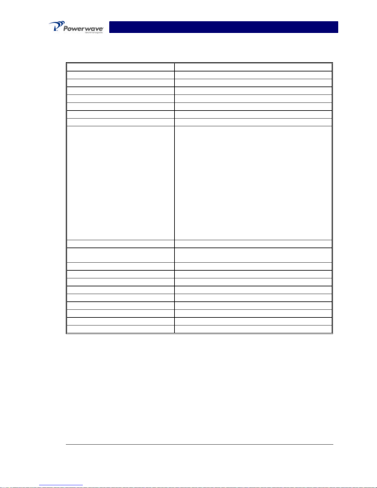
Table 1-1 SPA 9321-30C Single-Channel PCS Amplifier Functional Specifications
Frequency Range 1930-1990 MHz
Nominal Input Power -3.2 dBm
Total Output Power 30 watts maximum
RF Gain at 1960 MHz 48 +/- 0.5 dB
Gain Variation Over All Conditions:
Output Protection: Mismatch Protected
Input Port Return Loss: -16 dB (Min)
Out of Band Spurious: -50 dBc (max)
Spectral Mask Frequency Removed From Carrier GSM EDGE
Duty Cycle: Continuous
DC Input Power: -48 VDC; 3.75 amps typical; 4.8 amps max.
Heat Dissipation 512 BTUs typical
Operating Temperature: 0 ºC. to +60 ºC.
Storage Temperature: -40 ºC. to +75 ºC.
Operating Humidity: 5 % - 95 % Relative Humidity (Noncondensing)
Storage Humidity: 5 % - 95 % Relative Humidity (Noncondensing)
RF Input / Output Connector SMA Female (Input) / Type N Female (Output)
DC Power Connector 3-Pin D-Subminiature (20 A Contacts)
Data I/O Connector 20-Pin SCSI
Dimensions: 2.55” High, 9.48” Wide, 11.85” Deep
±2.0 dB
200 kHz -30 dBc -30
dBc
250 kHz -33 dBc -33
dBc
400 kHz -60 dBc -56
dBc
600 kHz -70 dBc -70
dBc
1200 kHz -73 dBc -73
dBc
1800 kHz -75 dBc -75
dBc
6000 kHz -80 dBc -80
dBc
-36 to –60 VDC, 180 watts typical; 230 watts max.
AAllll ssppeecciiffiiccaattiioonnss aarree ssuubbjjeecctt ttoo cchhaannggee wwiitthhoouutt nnoottiiccee.. CCoonnttaacctt tthhee ffaaccttoorryy ffoorr ccoommpplleettee ppeerrffoorrmmaannccee ddaattaa.
CCooppyyrriigghhtt PPoowweerrwwaavvee TTeecchhnnoollooggiieess,, IInncc..,, FFeebbrruuaarryy 22000033.. AAllll rriigghhttss rreesseerrvveed
044-xxxxx Rev. A 1-2 February 2003
d
.
 Loading...