

PowerWave NTGY81AC Installation & Service Manual

®
INSTALLATION & SERVICE
MANUAL
MULTICHANNEL
POWER AMPLIFIER
NTGY81AC
50 WATTS AVERAGE POWER
Powerwave Technologies, Inc. Tel: (714) 466-1000
1801 E. St. Andrew Place Fax: (714) 466-5800
Santa Ana, CA 92705 Web Site: www.powerwave.com
044-xxxxx Rev. x
1930-1990 MHz
04 April 2002

TABLE OF CONTENTS
Par. Section 1 Page
No. General Description No.
1-1 Introduction.....................................................................................................................1-1
1-2 General Description....................................................................................................... 1-1
1-3 Functional and Physical Specifications........................................................................... 1-1
Section 2
Installation
2-1 Introduction.....................................................................................................................2-1
2-2 Electrical Service Recommendations.............................................................................2-1
2-3 Unpacking and Inspection .............................................................................................. 2-1
2-4 Installation Instructions................................................................................................... 2-2
2-5 +26 VDC Power and Ground Connector P1...................................................................2-2
2-6 Alarms and Sensing Connector P2 ................................................................................ 2-3
2-7 Differential IIC Clock, Receive, and Transmit Connector P3.......................................... 2-4
2-8 IIC, Power, Alarms,and Controls Connector P4 ............................................................. 2-4
2-9 IIC, RS485, Power, and Other Signals Connector P5.................................................... 2-6
Section 3
Operating Instructions
3-1 Introduction.....................................................................................................................3-1
3-2 Initial Start-Up and Operating Procedures......................................................................3-1
Section 4
Principles of Operation
4-1 Introduction.....................................................................................................................4-1
4-2 RF Input Signal...............................................................................................................4-1
4-3 RF Output Load.............................................................................................................. 4-1
4-4 Amplifier Functional Description.....................................................................................4-1
4-4.1 Input Amplifier.................................................................................................................4-1
4-4.2 Predistortion Amplifier ....................................................................................................4-1
4-4.3 Driver Amplifier............................................................................................................... 4-2
4-4.4 Main Amplifier................................................................................................................. 4-2
4-4.5 Multifunction Board.........................................................................................................4-2
4-5 Amplifier Module Cooling................................................................................................4-2
4-5 Power Distribution...........................................................................................................4-2
044-xxxxx Rev. x
ii

TABLE OF CONTENTS (Continued)
Par. Section 5 Page
No. Maintenance No.
5-1 Introduction.....................................................................................................................5-1
5-2 Periodic Maintenance..................................................................................................... 5-1
5-3 Test Equipment Required For Test................................................................................ 5-1
5-4 Performance Test........................................................................................................... 5-2
5-4.1 Amplifier Performance Test............................................................................................ 5-2
5-5 Field Replacement of the Module................................................................................... 5-5
Section 6
Troubleshooting
6-1 Introduction.......................................................................................................................6-1
6-2 Troubleshooting................................................................................................................6-1
6-3 Return for Service Procedures .........................................................................................6-1
6-3.1 Obtaining an RMA ............................................................................................................6-1
6-3.2 Repackaging for Shipment...............................................................................................6-1
LIST OF ILLUSTRATIONS
Figure Page
No. No.
1-1 NTGY81AC Multichannel Power Amplifier ..................................................................... 1-3
2-1 +26 Vdc Power and Ground Connector P1....................................................................2-2
2-2 Alarms and Sensing Connector P2 ................................................................................ 2-3
2-3 Differential IIC Clock, Receive, and Transmit Connector P3.......................................... 2-4
2-4 IIC, Power, Alarms, and Controls Connector P4 ............................................................ 2-4
2-5 IIC, RS485, Power and Other Connector P5..................................................................2-6
4-1 NTGY81AC Multichannel Power Amplifier Functional Block Diagram........................... 4-2
5-1 NTGY81AC Amplifier Test Setup Diagram .................................................................... 5-3
LIST OF TABLES
Table Page
No. No.
1-1 NTGY81AC Multichannel Power Amplifier Functional Specifications..... ....................... 1-2
2-1 +26 Vdc Power and Ground Connector P1 Definition.................................................... 2-2
2-2 Alarms and Sensing Connector P2 Definition ................................................................ 2-3
2-3 Differential IIC Clock, Receive, and Transmit Connector P3 Definition.......................... 2-4
2-4 IIC, Power, Alarms, and Controls Connector P4 Definition............................................ 2-5
2-5 IIC, RS485, Power and Other Connector P5 Definition.................................................. 2-6
5-1 Periodic Maintenance..................................................................................................... 5-1
5-2 Test Equipment Required............................................................................................... 5-2
5-3 Multichannel Power Amplifier NTGY81AC Test Data Sheet.......................................... 5-4
6-1 Troubleshooting..............................................................................................................6-1
044-xxxxx Rev. x
iii

Section
1
GENERAL DESCRIPTION
1-1. INTRODUCTION
This manual contains information and procedures f or installation, operation, and maintenance of
Powerwave’s model NTGY81AC multic hannel power amplif ier (MCPA). T he m anual is organized
into six sections as follows:
Section 1. General Description
Section 2. Installation
Section 3. Operating Instructions
Section 4. Principles of Operation
Section 5. Maintenance
Section 6: Troubleshooting
1-2. GENERAL DESCRIPTION
The NTGY81AC is a linear, multichannel power amplif ier that operates in the 60 MHz frequency
band from 1930 MHz to 1990 MHz. It is designed to be mounted in an enclosure with EMI
containment. Its flat base plate allows f or mounting on a flat thermal-absorbing s urf ac e to pr ovide
adequate heat dissipation.
Each amplifier m odule has a power, alarm, and control c onnector that allows the host s ystem to
monitor the amplifier module performance. Primary power for the amplifier is +26 Vdc.
1-3. FUNCTIONAL AND PHYSICAL SPECIFICATIONS
Functional and physical specifications for the amplifier are listed in table 1-1.
044-xxxxx Rev. x 1-1

Table 1-1. NTGY81AC Multichannel Power Amplifier Functional Specifications
Frequency Range 1930-1990 MHz (60 MHz Bandwidth)
Maximum Average Input Power 13 dBm
Continuous Average Output Power 50 Watts
Spurious Emissions @ Maximum
Rated Output Power
(50 W / 47 dBm)
Frequency Offset Requirement Meas. Bandwidth
Max. Min.
0.885-1.25 MHz -47 dBc 30 kHz
1.25-1.98 MHz -16.5 dBm 37.5 kHz
1.98-2.25 MHz -58 dBc 30 kHz
>2.25 MHz -15 dBm 1 MHz
RF Gain 47 ±2 dB
Gain Flatness:
± 0.2 dB for any 1.25-MHz band within frequency range.
Output Protection: Mismatch Protected
Input Port Return Loss: VSWR 2:1 Max.
Out of Band Spurious: Less than -15 dBm / 1 MHz
DC Input Power:
+26 ± 0.5 Vdc, 260 mV p-p max. ripple, ≤500 watts
Operating Temperature: -15 ºC. to +85 ºC. (heatsink temperature)
Storage Temperature: -40 ºC. to +85 ºC.
Operating Humidity: 5 % - 95 % Relative Humidity (Noncondensing)
Storage Humidity: 5 % - 95 % Relative Humidity (Noncondensing)
Interface Connectors:
RF Input----------------------------------RF Output -------------------------------+26 Vdc Power and Ground --------Alarms and Sensing ------------------Differential IIC Clock, Rcv., Xmit.--IIC, Power, Alarms, Controls--------IIC, RS485, Power, Other Signals--
SMA Female
SMA Female
3W3 D-Sub (Connector P1)
14-Position Micro-Fit 3.0 (Connector P2)
6-Position Micro-Fit 3.0 (Connector P3)
26-Position High Density D-Sub (Connector P4)
18-Position Micro-Fit 3.0 (Connector P5)
Dimensions (inches): 11.00 x 14.50; height: 1.70
044-xxxxx Rev. x 1-2
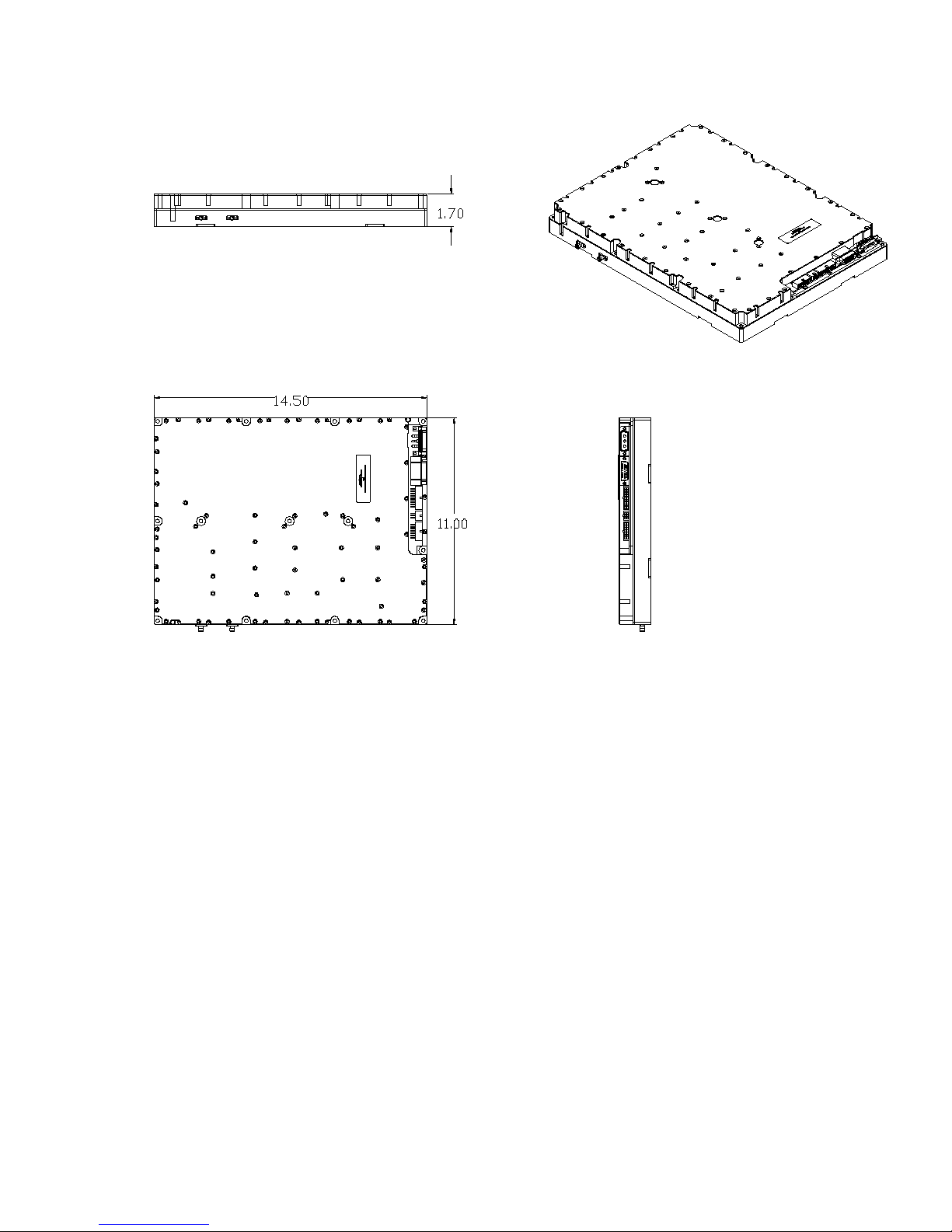
RF OUT RF IN
P1
P4
P5
P3
P2
Figure 1-1. NTGY81AC Multichannel Power Amplifier
044-xxxxx Rev. x 1-3

Section
2
INSTALLATION
2-1. INTRODUCTION
This section contains unpacking, inspection, and installation instructions and recommendations
for the Model NTGY81AC Multi Channel Power Amplifier. Carefully read all material in this
section prior to equipment unpacking or installation. Also read and review the operating
procedures in Section 3 prior to installing the equipm ent. It is im portant that the licens ee perf orm
these tasks corr ectly and in good faith. If applicable, carefully read the appropr iate parts of the
Federal Communications Commission (FCC) rules to determine how they apply to your
installation. DON'T TAKE CHANCES WITH YOUR LICENSE.
2-2. ELECTRICAL SERVICE RECOMMENDATIONS
Powerwave Technologies recomm ends that proper AC line conditioning and surge suppression
be provided on the primary AC input to the +26 Vdc power source. All electric al s ervic e s hould be
installed in accordance with the National Electrical Code, any applicable state or local codes, and
good engineering practice. Special consideration should be given to lightning protection of all
systems in view of the vulnerability of most transm itter sites to lightning. Lightning arrestors are
recommended in the service entrance. Straight, short ground runs are recommended. The
electrical service must be well grounded.
Each amplifier system should have its own circ uit br eak er , s o a f ailur e in one does not s hut of f the
whole installation. Circuit breakers should be thermal type, capable of handling the maximum
anticipated inrush current, in a load center with a master switch.
2-3. UNPACKING AND INSPECTION
This equipment has been operated, tested and calibrated at the factory. Carefully open the
container(s) and remove the amplifier module(s). Retain all packing material that can be
reassembled in the event that the unit must be returned to the factory.
CAUTION
Exercise care in handling equipment
during inspection to prevent damage
caused by rough or careless handling.
Visually inspect the amplifier module for damage that may have occurred during shipment. Check
for evidence of water damage, bent or warped chassis, loose screws or nuts, or extraneous
packing material in the connec tor. If the equipment is dam aged, a claim s hould be filed with the
carrier once the extent of any damage is assessed. We cannot stress too strongly the importance
of IMMEDIATE careful inspection of the equipment and the subsequent IMMEDIATE f iling of the
necessary claims against the carrier if necessary. If possible, inspect the equipment in the
presence of the delivery person. If the equipment is damaged, the carrier is your first area of
recourse. If the equipment is damaged and must be retur ned to the factory, write or phone for a
return authorization. Powerwave may not accept returns without a return authorization. Claims
for loss or damage m ay not be withheld from any payment to Powerwave, nor m ay any payment
due be withheld pending the outcome thereof. WE CANNOT GUARANTEE THE FREIGHT
CARRIER'S PERFORMANCE
044-xxxxx Rev. x 2-1
 Loading...