

PowerWave G3L-800-25-001 Installation & Service Manual

®
INSTALLATION & SERVICE
MANUAL
MULTICHANNEL
POWER AMPLIFIER
G3L-800-25-001
25 WATTS AVERAGE POWER
Powerwave Technologies, Inc. Tel: 949-757-0530
2026 McGaw Avenue Fax: 949-757-0941
Irvine, CA 92614 Web Site: www.powerwave.com
044-05058 Rev. A
869-894 MHz
15 JANUARY 1999

TABLE OF CONTENTS
Par. Section 1 Page
No. General Description No.
1-1 Introduction .............................................................................................1-1
1-2 General Description ...............................................................................1-1
1-3 Functional and Physical Specifications...................................................1-1
Section 2
Installation
2-1 Introduction .............................................................................................2-1
2-2 Electrical Service Recommendations......................................................2-1
2-3 Unpacking and Inspection.......................................................................2-1
2-4 Installation Instructions............................................................................2-2
2-5 Amplifier Module Power, Alarm, Control, and RF Connector..................2-2
2-6 Amplifier Module RS-232 Connector.......................................................2-4
Section 3
Operating Instructions
3-1 Introduction .............................................................................................3-1
3-2 Initial Start-Up and Operating Procedures ..............................................3-1
Section 4
Principles of Operation
4-1 Introduction .............................................................................................4-1
4-2 RF Input Signal .......................................................................................4-1
4-3 RF Output Load.......................................................................................4-1
4-4 Amplifier Functional Description..............................................................4-1
4-4.1 Predriver Amplifier...................................................................................4-1
4-4.2 Three Stage Driver Amplifier...................................................................4-1
4-4.3 Main Amplifier .........................................................................................4-2
4-4.4 Alarm Monitoring and Control..................................................................4-2
4-4.5 Loop Control Circuit ................................................................................4-2
4-5 Amplifier Module Cooling........................................................................4-2
4-6 Power Distribution...................................................................................4-2
2

TABLE OF CONTENTS (Continued)
Par. Section 5 Page
No. Maintenance No.
5-1 Introduction .............................................................................................5-1
5-2 Periodic Maintenance..............................................................................5-1
5-3 Test Equipment Required For Test.........................................................5-1
5-4 Performance Test....................................................................................5-2
5-4.1 Amplifier Performance Test.....................................................................5-2
5-5 Field Replacement of the Module ...........................................................5-7
Section 6
Troubleshooting
6-1 Introduction .............................................................................................6-1
6-2 Troubleshooting ......................................................................................6-1
6-3 Return for Service Procedures................................................................6-1
6-3.1 Obtaining an RMA...................................................................................6-1
6-3.2 Repackaging for Shipment......................................................................6-1
LIST OF ILLUSTRATIONS
Figure Page
No. No.
1-1 G3L-800-25-001 Amplifier Showing Front Panel.....................................1-3
1-2 G3L-800-25-001 Amplifier Showing Rear Panel.....................................1-4
2-1 Power, Alarm, Control, and RF Connector (D-Subminiature 21WA4, Male
Connector)......................................................................................................... 2-3
2-2 RS-232 Connector (on Rear of G3L-800-25-001 Module)......................2-4
4-1 G3L-800-25-001 Multi Channel Power Amplifier Functional Block Diagram
4-2
5-1 G3L-800-25-001 Amplifier Test Setup Diagram......................................5-3
LIST OF TABLES
Table Page
No. No.
1-1 G3L-800-25-001 Multichannel Power Amplifier Functional Specifications1-2
2-1 Amplifier Module Power, Alarm, Control, and RF Connector Definition..2-3
2-2 Amplifier Module RS-232 Connector Definition.......................................2-4
5-1 Periodic Maintenance..............................................................................5-1
5-2 Test Equipment Required ....................................................................... 5-2
3

5-3 Multichannel Power Amplifier Test Data Sheet.......................................5-4
6-1 Troubleshooting ......................................................................................6-1
4

Section
1
GENERAL DESCRIPTION
1-1. INTRODUCTION
This manual contains information and procedures for installation, operation, and
maintenance of Powerwave’s model G3L-800-25-001 multichannel power
amplifier. The manual is organized into six sections as follows:
Section 1. General Description
Section 2. Installation
Section 3. Operating Instructions
Section 4. Principles of Operation
Section 5. Maintenance
Section 6: Troubleshooting
1-2. GENERAL DESCRIPTION
The G3L-800-25-001 (see figures 1-1 and 1-2) is a linear, multichannel power
amplifier that operates in the 25 MHz frequency band from 869 MHz to 894 MHz.
It is designed as a self-contained module with EMI containment for use in both
indoor and outdoor North American cellular base stations. The G3L-800-25-001
accepts single channel and transmit voice RF signals. The G3L-800-25-001 uses
an internally generated tone to optimize its performance. The system operating
band (A or B) is externally provided to the G3L-800-25-001 so that it knows where
the tone frequency is going to be. If the operating band is A, then a tone at B
band is generated; if the operating band is B, then a tone at A band is generated.
Each amplifier module has a power, alarm, and control connector that allows the
host system to monitor the amplifier module performance. Primary power for the
amplifier is +27 Vdc.
1-3. FUNCTIONAL AND PHYSICAL SPECIFICATIONS
Functional and physical specifications for the amplifier are listed in table 1-1.
5

Table 1-1. G3L-800-25-001 Multichannel Power Amplifier Functional Specifications
Frequency Range 869-894 MHz (25 MHz Bandwidth)
Maximum Average Input Power -13 dBm
Continuous Average Output Power 25 Watts
Spurious Emissions -60 dBc maximum (820 MHz – 900 MHz)
-50 dBc maximum (all other frequencies)
RF Gain
Gain Flatness:
Gain Variation
(Temperature and Voltage)
Output Protection: Mismatch Protected
Input Port Return Loss: -12 dB at any given power level
Operating Temperature: 0 ºC. to +50 ºC. (room ambient)
Storage Temperature: -40 ºC. to +65 ºC. (room ambient)
Operating Humidity: 5% - 95% Relative Humidity (noncondensing) not to exceed
Storage Humidity: 5% - 95% Relative Humidity (noncondensing)
DC Input, Alarm, and Control
Connector:
RF Input Connector: 21WA4 (male, D-sub)
RF Output Connector: 21WA4 (male, D-sub)
Phase
Phase Tracking
IMD -60 dBc (8 carriers, continuous phase random, equal carrier
Output Return Loss -18 dB (at any power level)
Harmonic Output -45 dBc (at any number of carriers, any power level.)
Communications RS-485 interface for control and status
Status Indicators: POWER ON:
MINOR:
MAJOR:
Internally Generated Alarms Over temp., DC over voltage, Overpower, VSWR, Loop fail.
Externally Generated Alarms Fan failure: Open collector pulled low = amp functioning
Hot Swap Capable Unit is capable of being replaced without shutting down power.
DC Input Power:
Power Supply Current 15 amps max. (at max. RF power out)
Overload Protection 20 A (circuit breaker / on-off switch)
Dimensions (inches): Height: 13.82; width: 2.64; depth: 15.57
57±0.5 dB
±0.5 dB (869 MHz – 894 MHz)
±0.7dB (From 25 ºC, across specified temperature range.)
±0.7dB (From 27 V, across specified voltage range.)
0.024 grams of water per gram of dry air.
21WA4 (male, D-sub)
180±5 degrees (measured at 880 MHz, 25 ºC, any power level)
±10 degrees (from 25 ºC, across specified temperature range)
spacing of 1.25 MHz. Any power up to maximum average output
power.)
Green LED = Power applied
Yellow LED = Minor alarm (loop failure)
Red LED = Major alarm (module failure and shut down)
Open collector floating high = amp failure
+27±0.1 Vdc, 260 mV p-p max. ripple, ≤350 watts
6
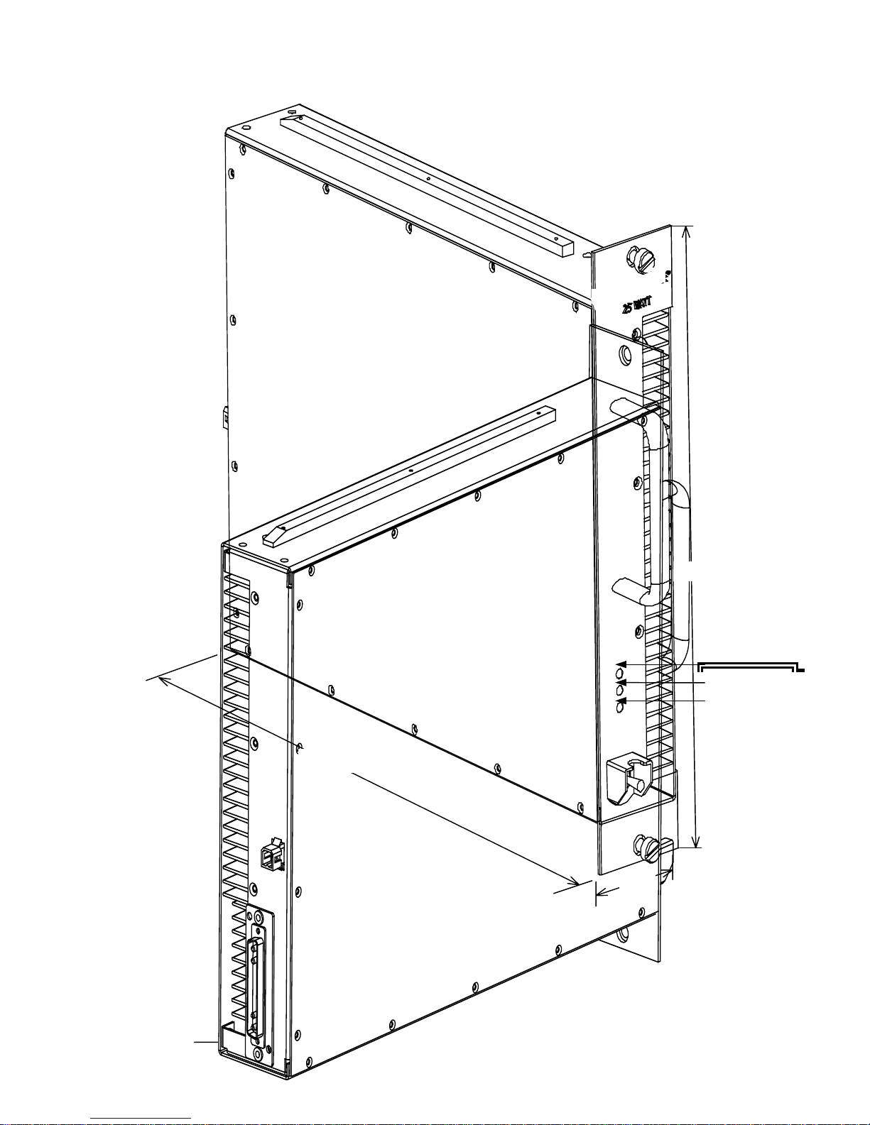
15.57
2.64
Figure 1-1. G3L-800-25-001 Amplifier Showing Front Panel
13.82
MINOR
MAJOR
7
 Loading...