

Page 1
Line-interactive UPS
PowerWalker VI 1200-3000 RLE
User Manual
IMPORTANT SAFETY INSTRUCTIONS
(SAVE THESE INSTRUCTIONS)
This manual contains important safety instructions. Please read and follow all instructions carefully during installation and operation of the unit. Read this
manual thoroughly before attempting to unpack, install, or operate your UPS.
CAUTION! To prevent the risk of fire or electric shock, install in a temperature and humidity controlled indoor area free of conductive contaminants. (See the
specifications for the acceptable temperature and humidity range.)
CAUTION! To reduce the risk of overheating the UPS, do not cover the UPS' cooling vents and avoid exposing the unit to direct sunlight or installing the unit
near heat emitting appliances such as space heaters or furnaces.
CAUTION! Do not attach non-computer-related items, such as medical equipment, life-support equipment, microwave ovens, or vacuum cleaners to UPS.
CAUTION! Do not plug the UPS input into its own output.
CAUTION! Do not allow liquids or any foreign object to enter the UPS. Do not place beverages or any other liquid-containing vessels on or near the unit.
CAUTION! In the event of an emergency, press the OFF button and disconnect the power cord from the AC power supply to properly disable the UPS.
CAUTION! Do not attach a power strip or surge suppressor to the UPS.
CAUTION! Unplug the UPS prior to cleaning and do not use liquid or spray detergent.
INSTALLING YOUR UPS SYSTEM
UNPACKING
The box should contain the following:
(1) UPS Unit x 1; (2) User Manual1; (3) USB Cable x 1; (4) RS232 Cable x 1;
HOW TO DETERMINE THE POWER REQUIREMENTS OF YOUR EQUIPMENT
1. Ensure that the equipment plugged into the battery power-supplied outlets does not exceed the UPS unit’s rated capacity. If rated unit capacities are
exceeded, an overload condition may occur and cause the UPS unit to shut down or the fuse blow.
2. There are many factors that can affect the amount of power that your computer system will require. For optimal system performance keep the load
below 80% of the unit’s rated capacity.
HARDWARE INSTALLATION GUIDE
1. Your new UPS may be used immediately upon receipt. However, recharging the battery for at least 8 hours is recommended to ensure that the battery's
maximum charge capacity is achieved. Charge loss may occur during shipping and storage. To recharge the battery, simply leave the unit plugged into
an AC outlet. The unit will charge in both the on and off position.
2. With the UPS unit off and unplugged, connect the computer, monitor, and any externally powered data storage device.
3. Plug the UPS into a 2 pole, 3 wire grounded receptacle (wall outlet). Make sure the wall branch outlet is protected by a fuse or circuit breaker and does
not service equipment with large electrical demands.
4. Depress the power switch to turn the unit on. The LCD indicator light will illuminate and the unit will "beep".
5. To maintain optimal battery charge, leave the UPS plugged into an AC outlet at all times.
6. To store your UPS for an extended period, cover it and store with the battery fully charged. Recharge the battery every three months to ensure battery
life.
ROUTINE MAINTENANCE AND STORAGE
ROUTINE MAINTENANCE
1. Use dry soft clothes to clean the front panel and plastic parts. Do not use any detergent that contains alcoholic ingredient.
2. The expected lifetime of the battery is around 3 years. Improper operation and harsh environment will reduce the actual lifetime.
3. Unplug the UPS from power inlet if the UPS will not operate for long period of time.
STORAGE
1. First turn off your UPS and disconnect its power cord from the wall outlet. Disconnect all cables connected the UPS to avoid battery drain.
2. The UPS should be stored in a cool dry location.
3. Make sure the battery is fully charged before the UPS is stored.
4. For extended storage in moderate climates, the battery should be charged for 12 hours every 3 months by plugging the power cord into the wall
receptacle and turning on the main switch. Repeat it every 2 months in high temperature locations.
BASIC OPERATION
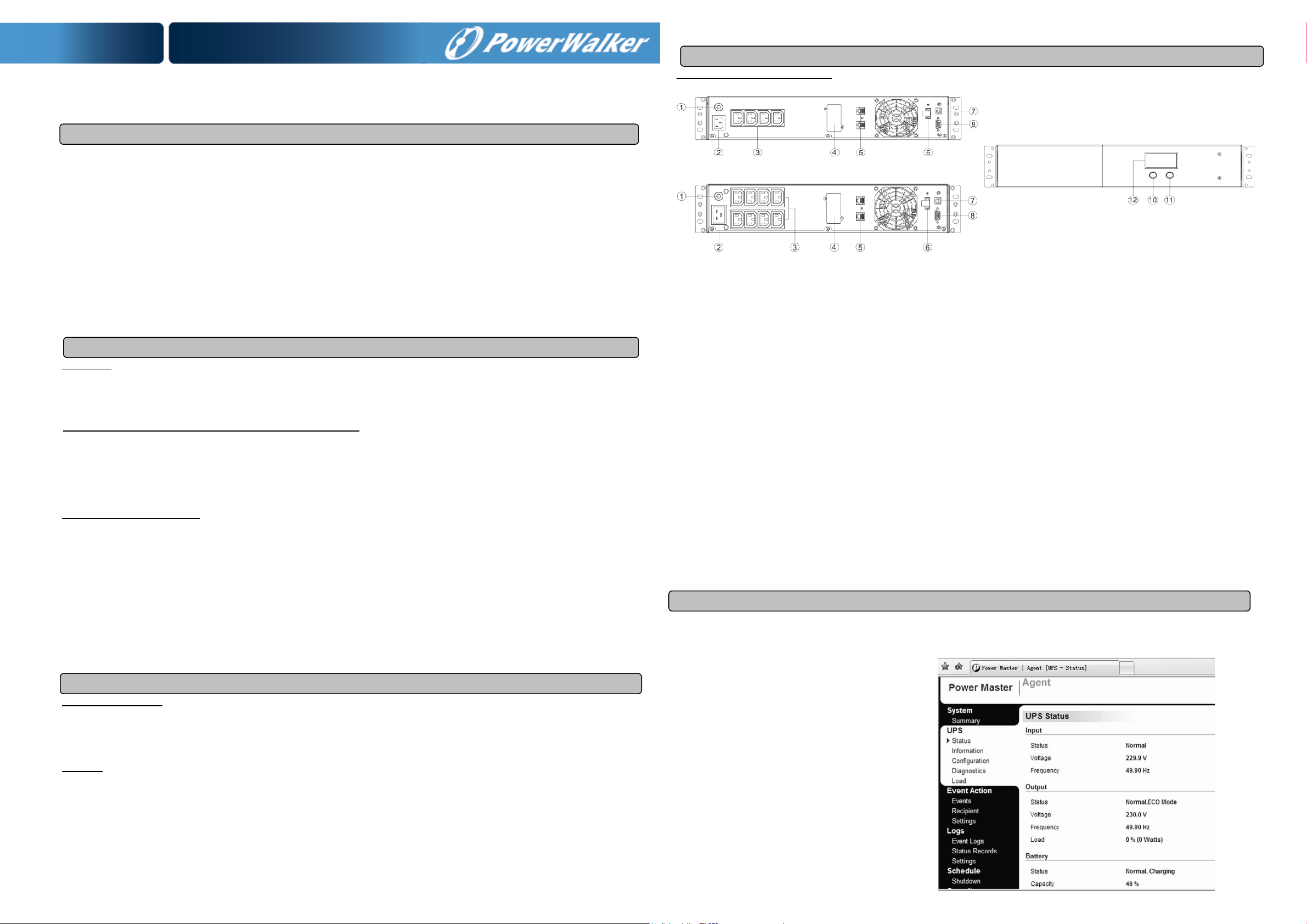
FRONT AND TOP PANEL DESCRIPTION
PowerWalker VI 1200/ 2200 RLE Front View
PowerWalker VI 3000 RLE
1. Input Circuit Breaker
The circuit breaker provides optimal overload protection.
2. AC Inlet
Connect to utility power through the input power cord.
3. AC outlet
The UPS provides outlets for connected equipment to insure temporary uninterrupted operation during a power failure and against surges and spikes.
4. SNMP/HTTP Network Port
The SNMP/HTTP port provides remote monitoring and management of your UPS over a network.
5. RJ45/11 Communication Protection Ports
Communication protection ports will protect any standard modem, fax, telephone line, or network cable.
6. EPO Port
Enables an emergency UPS Power-Off from a remote location. EPO terminal open, the UPS will turn off and the output shutdown immediately.
7. USB Port
This port allows connection and communication form the USB port on the computer to the UPS unit.
8. Serial Port
This port allows connection and communication from the DB9 serial on the computer to the UPS unit. The UPS communicates its status to the
software.
9. Not used
10. Power On/Off Switch
Press the power switch to turn the UPS ON or OFF.
11. Mute Button
The audible alarm can be turned off/on by pressing this button.
12. LCD Display
The LCD will display the UPS status including input voltage, output voltage, runtime, percentage of load and battery, etc.
SOFTWARE DOWNLOAD
Power Master management software provides a user-friendly interface for your power systems. The graphic user-interface is intuitive and displays essential
power information at a glance. Please follow procedure below to install the software.
Installation procedure:
1.Download Power Master from the website:
http://www.powermaster. powerwalker.com
2.Double-click the file and follow the installation steps.
3.When your computer restarts, the Power Master
software will appear as a blue icon located in the
system tray.
Page 2
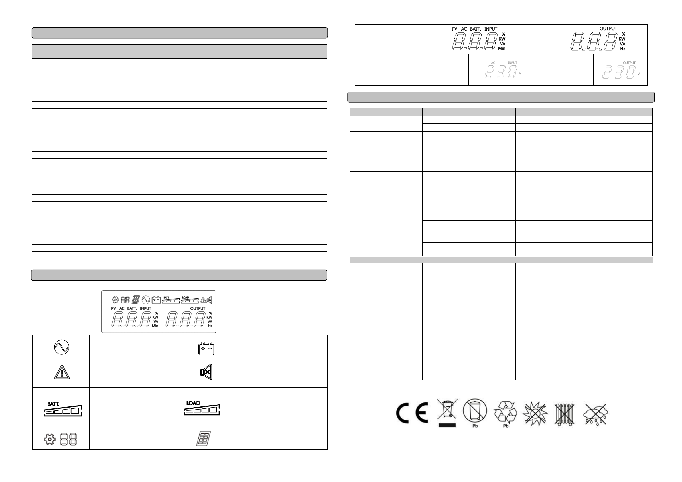
Line mode
Bat-mode
Alarm/Fault
Sound disable
(Press the mute key 3s to disable
and enable the buzzer sound)
Bat mode: battery capacity
Line mode:
1. Battery charging: cycle lighting
2. Battery full charged: lighting
3. Line mode without charger:
battery capacity
Load capacity
Setting Item
PV Mode
Initial
AC INPUT(Voltage)
V
OUTPUT
(Voltage)
V
Problem
Possible Cause
Solution
The UPS does not perform
expected runtime.
Batteries are not fully charged.
Recharge the battery by leaving the UPS plugged in.
Battery is slightly worn out.
Contact Technical Support.
The UPS will not turn on.
The on/off switch is designed to prevent
damage by rapidly turning it off and on.
Turn the UPS off. Wait 10 seconds and then turn the UPS on.
The unit is not connected to an AC outlet.
The unit must be connected to a 220-240V 50Hz outlet.
The battery is worn out.
Contact Technical Support.
Mechanical problem.
Contact Technical Support.
Outlets do not provide power to
equipment
Fuse is blown due to overload
Turn the UPS off and unplug at least one piece connected
equipment. Unplug the power cord of the UPS then remove the fuse
compartment beneath the power inlet of the UPS and replace the
blown fuse with a spare one. Lock the compartment back to the UPS.
Connect power cord then turn the UPS on. Make sure that your spare
fuse meets the specification.
Batteries are discharged
Allow the unit to recharge for at least 4 hours.
Unit has been damaged by a surge or spike.
Contact Technical Support.
Software is inactive
The network cable is not connected.
Connect the network cable to the UPS unit and a network port on the
hub.
Software setting problem.
Please read and follow NetAgent utility instruction during installation
and operation of the NetAgent software, or contact technical support.
Fault
Fault code F09
Output Short :
Output circuit short.
1. Shut down the UPS
2. Your attached equipment may have problems, please remove
them and check again.
Fault code F11
Battery high: Battery voltage is too high.
1. Shut down the UPS
2.Check the counts of Battery
Fault code F12
Battery Low :
Battery voltage is too low.
1. Shut down the UPS
2. Check the counts of Battery
3.Check battery connector when use battery packages.
Fault code F14
Overload in line Mode:
Your equipment requires more power than the
UPS can provide. It will transfer to Bypass
Mode.
Shut off non-essential equipment.If this solves the overload problem,
the UPS will transfer to normal operation.
Fault code F14
Overload in Battery Mode : Your equipment
requires more power than the UPS can provide.
It will shutdown.
Shut off non-essential equipment.If this solves the overload problem,
the UPS will transfer to normal operation.
Fault code F18
Fan fail :
Fan has been damaged.
1.Shut down the UPS
2.Replace the fan
Fault code F19
Over Temperature :
High ambient temperature The LCD will display
E11
1. Shut down the UPS. Restart the UPS to Check the fan for operation
and if the ventilation hole has been covered
2. Contact Technical Support.
Model
PowerWalker
VI 1200 RLE
PowerWalker
VI 2200 RLE
PowerWalker
VI3000 RLE
Capacity (VA)
1200VA
2200VA
3000VA
Capacity (Watts)
720W
1320W
1800W
Input
Input Voltage Range
165V~290V
Frequency Range
50Hz +/- 5 Hz
Output
On Battery Output Voltage
Sine Wave at 230Vac +/-10%
On Battery Output Frequency
50Hz +/-1%
Overload Protection
On Utility: Fuse, On Battery: Internal Current Limiting
AVR Function
Boost Function
Yes
Buck Function
Yes
Physical
Total # of UPS Receptacles
IEC C13 x 4
IEC C13 x 8
Maximum Dimensions (H x D x W)
88mm x 430mm x 438mm
Weight (Kg)
11.93
16.47
21.78
Battery
Sealed Maintenance Free Lead Acid Battery
24V (2x12V/7.2Ah)
24V (2x12V/9Ah)
24V (4x12V/7.2Ah)
Typical Recharge Time
4 Hours
Warning Diagnostics
Indicators
Using AC / Using Battery / Fault
Communication
Software
Yes
Environmental
Operating Temperature
0C to 40C
Operating Relative Humidity
0 to 90% NON-CONDENSING
Management
Auto-Charger
Yes
Auto-Restart
Yes
DEFINITIONS FOR ILLUMINATED LCD INDICATORS
TECHNICAL SPECIFICATIONS
TROUBLE SHOOTING
LCD Indication
All rights reserved. Reproduction without permission is prohibited.
Page 3

Line-interactive USV
PowerWalker VI 1200-3000 RLE
Anleitung
WICHTIGE SICHERHEITSHINWEISE
(Bewahren Sie diese Anleitung auf)
Dieses Handbuch enthält wichtige Sicherheitshinweise. Bitte lesen und befolgen Sie alle Anweisungen während der Installation und des Betriebs des
Gerätes sorgfältig. Lesen Sie dieses Handbuch sorgfältig durch, bevor Sie Ihre USV auspacken, installieren oder betreiben.
ACHTUNG! Um die Gefahr eines Brandes oder eines elektrischen Schlages zu vermeiden, installieren Sie das Gerät in einem temperatur- und
feuchtigkeitskontrollierten Innenbereich, der frei von leitfähigen Verunreinigungen ist. (Siehe Spezifikationen für den zulässigen Temperatur- und
Feuchtebereich.)
ACHTUNG! Um das Risiko einer Überhitzung der USV zu verringern, sollten Sie die Kühlöffnungen der USV nicht abdecken und das Gerät nicht direkter
Sonneneinstrahlung aussetzen oder in der Nähe von wärmeabgebenden Geräten wie Raumheizungen oder Öfen installieren.
ACHTUNG! Schließen Sie keine nicht computerbezogenen Geräte wie medizinische Geräte, lebenserhaltende Geräte, Mikrowellenherde oder Staubsauger
an UPS an.
ACHTUNG! Schließen Sie den USV-Eingang nicht an seinen eigenen Ausgang an.
ACHTUNG! Lassen Sie keine Flüssigkeiten oder Fremdkörper in die USV eindringen. Stellen Sie keine Getränke oder andere Flüssigkeitsbehälter auf oder
neben das Gerät.
ACHTUNG! Drücken Sie im Notfall die OFF-Taste und ziehen Sie das Netzkabel aus der Steckdose, um die USV ordnungsgemäß zu deaktivieren.
ACHTUNG! Schließen Sie keine Steckdosenleiste oder Überspannungsschutz an die USV an.
ACHTUNG! Ziehen Sie vor der Reinigung den Netzstecker und verwenden Sie keine Flüssig- oder Sprühreiniger.
INSTALLATION IHRES USV SYSTEMS
Auspacken
Die Verkaufsverpackung sollte folgenden Inhalt haben:
(1) USV Einheit1; (2) Bedienungsanleitung1; (3) USB Kabel x 1; (4) RS232 Kabel x 1
Wie Sie den Leistungsbedarf Ihrer Anlage ermitteln
1. Vergewissern Sie sich, dass das an die Steckdosen angeschlossene Gerät die Nennkapazität der USV-Anlage nicht überschreitet. Bei Überschreitung
der Geräte-Nennkapazitäten kann es zu einer Überlastung kommen, die zum Abschalten der USV-Anlage oder zum Auslösen der Sicherung führen
kann.
2. Es gibt viele Faktoren, die den Stromverbrauch Ihres Computersystems beeinflussen können. Für eine optimale Systemleistung halten Sie die Last
unter 80% der Nennkapazität des Gerätes.
HARDWARE INSTALLATIONSANLEITUNG
1. Ihre neue USV kann sofort nach Erhalt verwendet werden. Es wird jedoch empfohlen, den Akku mindestens 8 Stunden lang aufzuladen, um
sicherzustellen, dass die maximale Ladekapazität des Akkus erreicht wird. Während des Transports und der Lagerung kann es zu Ladungsverlusten
kommen. Um den Akku aufzuladen, lassen Sie das Gerät einfach an eine Steckdose angeschlossen. Das Gerät lädt sowohl in der Ein- als auch in der
Aus-Position.
2. Schließen Sie bei ausgeschalteter, und nicht ans Stromnetz angeschlossener USV den Computer, Monitor und ggf. andere Gerät an.
3. Schließen Sie die USV an eine 2-polige, 3-adrige geerdete Steckdose (Wandsteckdose) an. Stellen Sie sicher, dass die Wandsteckdose durch eine
Sicherung oder einen Schutzschalter geschützt ist und keine Geräte mit hohen elektrischen Anforderungen versorgt werden.
4. Drücken Sie den Netzschalter um das Gerät einzuschalten. Die LCD-Anzeige leuchtet auf und das Gerät „piept“ kurz
5. Um einen optimalen Batterieladezustand zu erhalten lassen Sie die USV immer ans Netz angeschlossen.
ROUTINEWARTUNG UND LAGERUNG
ROUTINEWARTUNG
1. Reinigen Sie die Kunststoffteile mit trockenem, weichem Tuch. Verwenden Sie kein Reinigungsmittel, das alkoholische Bestandteile enthält.
2. Die erwartete Lebensdauer der Batterien beträgt ca. 3 Jahre. Unsachgemäßer Betrieb und ungünstige Umgebungsbedingungen reduzieren die
tatsächliche Lebensdauer.
3. Trennen Sie die USV vom Stromnetz, wenn die USV über einen längeren Zeitraum nicht genutzt wird.
LAGERUNG
1. Schalten Sie Ihre USV aus und trennen Sie das Netzkabel. Trennen Sie alle Ausgangskabel, um eine Entladung der Batterie zu vermeiden.
2. Die USV sollte an einem kühlen, trockenen Ort gelagert werden.
3. Stellen Sie sicher, dass die Batterien vollständig geladen sind, bevor Sie die USV lagern.
4. Bei längerer Lagerung in gemäßigten Klimazonen sollte der Akku alle 3 Monate für 12 Stunden geladen werden, indem das Netzkabel in die
Wandsteckdose gesteckt und der Hauptschalter eingeschaltet wird. Bei hohen Temperaturen alle 2 Monate wiederholen.
GRUNDLEGENDE FUNKTIONSWEISE
VORDER- UND RÜCKSEITENBESCHREIBUNG
PowerWalker VI 1200/ 2200 RLE Forderansicht
PowerWalker VI 3000 RLE
1. Eingangsstromsicherung
Die Sicherung bietet einen optimalen Überlastschutz.
2. Netzeingang
Anschluss an das Stromnetz über das Eingangskabel.
3. Netzausgang
Anschlüsse für zu versorgende Geräte. Gewährleisten einen geschützten ununterbrochenen Betrieb bei Stromausfall.
4. SNMP/HTTP Netzwerkanschluss
Einschub für eine optional erhältliche Netzwerkkarte zu Fernüberwachung
5. RJ45/11 Überspannungsschutz für Netzwerkanschluss
Netzwerkanschluss Ports für Standardmodem, Fax, Telefonleitung oder Netzwerkkabel.
6. EPO Port (Notabschaltung)
Ermöglicht eine Notabschaltung der USV von einem entfernten Standort. EPO-Port geöffnet, die USV sich und alle Ausgänge sofort ab.
7. USB Anschluss
Dieser Anschluss ermöglicht die Kommunikation zwischen USB-Anschluss des Computers und USV-Gerät.
8. Serieller Anschluss
Dieser Anschluss ermöglicht die Softwarekommunikation zwischen dem seriellen DB9 Anschluss des Computers und der USV-Einheit.
9. Nicht genutzt
10. AN/AUS Schalter
Drücken Sie den Netzschalter um die USV an- und auszuschalten.
11. Stummschalttaste
Der akustische Alarm mit dieser Taste an- und ausgeschaltet werden.
12. LCD Anzeige
The Die LCD-Anzeige zeigt den USV-Status wie Eingangsspannung, Ausgangsspannung, Laufzeit, Prozentsatz der Last und Batterie usw. an
SOFTWARE DOWNLOAD
Die Power Master Software bietet eine benutzerfreundliche Oberfläche für Ihre USV. Die grafische Benutzeroberfläche ist intuitiv bedienbar und zeigt
wesentliche Leistungsinformationen auf einen Blick. Bitte gehen Sie wie folgt vor, um die Software zu installieren.
Installationsablauf:
1. Laden Sie die Power Master Software von der Website herunter:
http://www.powermaster. powerwalker.com
2. Doppelklicken Sie auf die Datei und folgen Sie den
Installationsanweisungen.
3. Nach dem Neustart erscheint die Power Master Software
als blaues Symbol in der Systemablage.
Page 4

Netzbetrieb
Batteriemodus
Alarm/Fehler
Ton ausschalten
(Drücken Sie die
Stummschaltungstaste für 3
Sekunden, um den Summer zu
aktivieren bzw. zu deaktivieren.
Batteriemodus: Batteriekapazität
Netzbetrieb:
1. Batterie wird geladen: zyklische
Beleuchtung
2. Batterie vollgeladen: Beleuchtung
3. Netzbetrieb ohne Laden:
Batteriekapazität
Last-Kapazität
Einstellungen
PV Modus
Initial
AC EINGANG
(Spannung)
V
AUSGANG
(Spannung)
V
Problem
Mögliche Ursache
Lösung
Autonomiezeit der USV ist nicht
wie erwartet
Die Batterien sind nicht vollständig geladen.
Laden Sie die Batterie, indem Sie die USV angeschlossen lassen.
Die Batterien sind abgenutzt
Wenden Sie sich an den technischen Support.
Die USV lässt sich nicht
einschalten
Der Ein/Aus-Knopf ist so konzipiert, dass er
Schäden durch schnelles Ein- und
Ausschalten verhindert.
Schalten Sie die USV aus. Warten Sie 10 Sekunden und schalten
Sie dann die USV wieder ein.
Das Gerät ist nicht an eine Steckdose
angeschlossen.
Das Gerät muss an eine 220-240V 50Hz Steckdose angeschlossen
werden.
Die Batterie ist abgenutzt.
Wenden Sie sich an den technischen Support.
Mechanisches Problem.
Wenden Sie sich an den technischen Support.
Ausgänge versorgen die Geräte
nicht mit Strom.
Sicherung ist aufgrund von Überlast
durchgebrannt.
Schalten Sie die USV aus und trennen Sie mindestens ein
angeschlossenes Gerät. Trennen Sie die USV vom Stromnetz,
entfernen Sie das Sicherungsfach unter dem Netzeingang der USV
und ersetzen Sie die durchgebrannte Sicherung durch eine
Ersatzsicherung. Stellen Sie sicher, dass Ihre Ersatzsicherung den
Spezifikationen entspricht.
Batterien sind entladen
Laden Sie die USV mindestens 4 Stunden lang auf.
Das Gerät wurde durch eine Überspannung
beschädigt.
Wenden Sie sich an den technischen Support.
Software ist inaktiv
Das Kommunikationskabel ist nicht richtig
angeschlossen.
Stellen Sie sicher, dass das Kommunikationskabel zwischen der
USV und der Last richtig verbunden ist.
Softwareeinstellung ist nicht korrekt
Bitte lesen und befolgen Sie die NetAgent-Anleitung oder wenden
Sie sich an den technischen Support.
Fehler
Fehlercode F09
Output Short : Kurzschluss am Ausgang
1. Schalten Sie die USV aus
2. Ein angeschlossenes Gerät verursacht einen Kurzschluss.
Bitte entfernen Sie das Gerät und prüfen Sie erneut.
Fehlercode F11
Battery high: Akkuspannung zu hoch.
1. Schalten Sie die USV aus
2. Prüfen Sie die Akkuspannung
Fehlercode F12
Battery Low : Akkuspannung ist zu niedrig
1. Schalten Sie die USV aus
2. Prüfen Sie die Akkuspannung
3. Prüfen Sie das Batteriekabel bei externen Akkupacks
Fehlercode F14
Überlast im Netzbetrieb
Die angeschlossenen Geräte brauchen mehr
Leistung als die USV zur Verfügung stellen
kann. USV wird in den Beipassbetrieb schalten.
Entfernen Sie nicht benötigte Geräte und prüfen Sie ob das Problem
behoben ist. USV schaltet wieder in den Normalbetrieb.
Fehlercode F14
Überlast im Akkubetrieb:
Die angeschlossenen Geräte brauchen mehr
Leistung als die USV zur Verfügung stellen
kann. USV wird abschalten.
Entfernen Sie nicht benötigte Geräte und prüfen Sie ob das Problem
behoben ist. USV schaltet wieder in den Normalbetrieb.
Fehlercode F18
Lüfter Fehler :
Lüfter ist beschädigt.
1.Schalten Sie die USV aus
2.Tauschen Sie den Lüfter
Fehlercode F19
Übertemperatur :
Zu hohe Umgebungstemperatur.
Das Display zeigt E11
1. Schalten Sie die USV aus und starten Sie die USV neu. Prüfen Sie ob
der Lüfter funktioniert und keine Lüftungsöffnungen abgedeckt sind.
2. Kontaktieren Sie den technischen Support.
Modell
PowerWalker
VI 1200 RLE
PowerWalker
VI 2200 RLE
PowerWalker
VI3000 RLE
Kapazität (VA)
1200VA
2200VA
3000VA
Kapazität (Watt)
720W
1320W
1800W
Eingang
Eingangsspannungsbereich
165V~290V
Frequenzbereich
50Hz +/- 5 Hz
Ausgang
Batterie-Ausgangsspannung
Sinuswelle mit 230Vac +/-10%
Batterie-Ausgangsfrequenz
50Hz +/-1%
Überlastschutz
Am Eingang: Sicherung, Im Batteriemodus: Interne Strombegrenzung
AVR Funktion (automarischer Spannungsausgleich)
Hochspann-Funktion bei niedriger Spannung
Ja
Spannungssenkung-Funktion bei hoher Spannung
Ja
Physikalische Daten
Anzahl von Anschlüssen
IEC C13 x 4
IEC C13 x 8
Abmessungen (H x T x B)
88mm x 430mm x 438mm
Gewicht (Kg)
11.93
16.47
21.78
Batterie
Versiegelte wartungsfreie Blei-Säure-Batterie
24V (2x12V/7.2Ah)
24V (2x12V/9Ah)
24V (4x12V/7.2Ah)
Typische Wiederaufladezeit
4 Stunden
Fehlerdiagnose
Indikatoren
Netzbetrieb / Batteriebetrieb / Fehler
Kommunikation
Software
Ja
Umgebung
Betriebstemperatur
0C bis 40C
Relative Luftfeuchtigkeit
0 bis 90% nicht-kondensierend
Management
Auto-Laden
Ja
Auto-Neustart
Ja
BEDEUTUNG DER BELEUCHTETE LCD-ANZEIGEN
TECHNISCHE DATEN
FEHLERDIAGNOSE
LCD-Anzeigen
All rights reserved. Reproduction without permission is prohibited.
Page 5

UPS Line-interactive
PowerWalker VI 1200-3000 RLE
Instrukcja obsługi
WAŻNE INSTRUKCJE BEZPIECZEŃSTWA
(KONIECZNIE ZACHOWAJ TĄ INSTUKCJĘ)
Niniejsza instrukcja zawiera ważne instrukcje bezpieczeństwa. Należy uważnie przeczytać i przestrzegać wszystkich instrukcji podczas instalacji i obsługi
urządzenia. Przed rozpakowaniem, instalacją lub obsługą UPS-a należy się dokładnie zapoznać z treścią tej instrukcji.
UWAGA! Aby uniknąć ryzyka pożaru lub porażenia prądem, montaż urządzenia powinien przebiegać w pomieszczeniu o kontrolowanej temperaturze i
wilgotności, wolnym od zanieczyszczeń. (Zapoznaj się ze specyfikacją dopuszczalnego zakresu temperatur i wilgotności).
UWAGA! Aby zmniejszyć ryzyko przegrzania UPS, nie należy zakrywać otworów wentylacyjnych UPS-a i unikać wystawiania urządzenia na bezpośrednie
działanie promieni słonecznych lub instalowania go w pobliżu urządzeń emitujących ciepło, takich jak grzejniki lub piece.
UWAGA! Nie wolno podłączać do UPS-a przedmiotów niezwiązanych ze sprzętem komputerowym, takim jak sprzęt medyczny, sprzęt podtrzymujący życie,
kuchenki mikrofalowe lub odkurzacze.
UWAGA! Nie podłączaj wejścia UPS-a do jego wyjścia.
UWAGA! Nie należy dopuszczać do sytuacji, aby do UPS-a dostawały się ciecze lub jakiekolwiek obce przedmioty. Nie umieszczaj napojów ani żadnych
innych pojemników zawierających ciecz na urządzeniu lub w jego pobliżu.
UWAGA! W razie nagłej potrzeby naciśnij przycisk OFF i odłącz przewód zasilający od źródła zasilania, aby właściwie wyłączyć UPS.
UWAGA! Nie podłączaj do UPS-a zasilacza ani listwy przeciwprzepięciowej.
UWAGA! Odłącz zasilacz awaryjny UPS z prądu, przed przystąpieniem do jego czyszczenia i nie używaj środków czyszczących w płynie lub w sprayu.
ROZPAKOWYWANIE
Karton powinien zawierać następujące elementy:
(1) Zasilacz awaryjny UPS 1; (2) Instrukcję obsługi 1; (3) Kabel USB x 1; (4) Kabel RS232 x 1;
W JAKI SPOSÓB OKREŚLIĆ WYMOGI ZASILANIA TWOJEGO SPRZĘTU
1. Upewnij się, że sprzęt podłączony do gniazd zasilanych z baterii nie przekracza znamionowej mocy danego UPS-a. Jeśli przekroczone zostaną
znamionowe pojemności baterii zasilacza awaryjnego, może wystąpić przeciążenie i spowodować wyłączenie jednostki UPS lub przepalenie
bezpiecznika.
2. Istnieje wiele czynników, które mogą mieć wpływ na wielkość energii wymaganej przez system komputera. Aby uzyskać optymalną wydajność systemu,
należy utrzymywać obciążenie poniżej 80% znamionowej mocy UPS-a.
INSTRUKCJA MONTAŻU SPRZĘTU
Twój nowy UPS może być użyty natychmiast po zakupie. Zaleca się jednak ładowanie baterii przez co najmniej 8 godzin, aby zapewnić maksymalną
pojemność baterii. Podczas wysyłki lub przechowywania mogła nastąpić utrata ładunku baterii. Aby naładować baterię, po prostu zostaw urządzenie
podłączone do gniazdka elektrycznego. Urządzenie będzie się ładować, zarówno będąc włączone lub wyłączone.
1. Po wyłączeniu i odłączeniu zasilacza UPS podłącz komputer, monitor i wszelkie inne zewnętrzne urządzenie do przechowywania danych.
2. Podłącz zasilacz awaryjny do 2-biegunowego, 3-przewodowego uziemionego gniazdka elektrycznego. Upewnij się, że dane gniazdko elektryczne jest
chronione przez bezpiecznik lub wyłącznik i nie obsługuje sprzętu o dużych wymaganiach elektrycznych.
3. Naciśnij przycisk zasilania, aby włączyć urządzenie. Wyświetlacz LCD zaświeci się, a urządzenie wyemituje sygnał dźwiękowy.
4. Aby utrzymać optymalne naładowanie baterii, pozostaw zasilacz UPS podłączony do gniazdka sieciowego przez cały czas użytkowania urządzenia.
5. Do przechowywania UPS-a przez dłuższy czas, należy go przykryć i przechowywać z całkowicie naładowaną baterią. Ponadto baterię należy ładować
co trzy miesiące, aby zapewnić jej odpowiednią żywotność.
RUTYNOWY PRZEGLĄD
1. Użyj suchej miękkiej szmatki, aby wyczyścić przedni panel i plastikowe części UPS-a. Nie należy używać żadnych detergentów zawierających alkohol.
2. Oczekiwana żywotność baterii wynosi około 3 lat. Nieprawidłowa obsługa i trudne warunki pracy skracają jej rzeczywisty okres eksploatacji.
3. Odłącz zasilacz z gniazda sieciowego, jeśli UPS nie będzie wykorzystywany przez dłuższy czas.
PRZECHOWYWANIE
1. Wyłącz najpierw UPS i odłącz przewód zasilający z gniazdka. Odłącz wszystkie kable podłączone do UPS, aby uniknąć rozładowania baterii.
2. UPS powinien być przechowywany w chłodnym, suchym miejscu.
3. Upewnij się, że bateria UPS-a jest w pełni naładowana, przed przystąpieniem do przechowywania urządzenia.
4. W przypadku dłuższego przechowywania w umiarkowanym klimacie, baterię należy ładować przez 12 godzin co 3 miesiące, podłączając przewód
zasilający do gniazdka elektrycznego i włączając główny włącznik. W lokacjach z wysoką temperaturą ładowanie powtarzaj co 2 miesiące.
MONTAŻ ZASILACZA AWARYJNEGO UPS
RUTYNOWY PRZEGLĄD I PRZECHOWYWANIE
PODSTAWOWE DZIAŁANIE
OPIS PRZEDNIEGO I TYLNEGO PANELU
PowerWalker VI 1200/ 2200 RLE Przód
PowerWalker VI 3000 RLE
1. Bezpiecznik obwodu wejścia
Bezpiecznik zapewnia optymalną ochronę przed przeciążeniem.
2. Gniazdo AC wejściowe
Podłącz do zasilania sieciowego wykorzystując przewód zasilający.
3. Gniazda AC wyjściowe
UPS posiada gniazdka przeznaczone dla podłączonego sprzętu, w celu zapewnienia tymczasową nieprzerwaną pracę tych urządzeń, w przypadku
awarii zasilania, przepięć oraz nagłych skoków napięcia.
4. Slot karty SNMP
Karta (opcjonalna) SNMP umożliwia zdalny monitoring i zarządzanie twoim zasilaczem awaryjnym UPS przez Internet.
5. Ochrona przepięciowa portu Ethernet
Wejście i wyjścia RJ-45 do ochrony przepięciowej urządzeń sieciowych.
6. Port EPO
Umożliwia awaryjne wyłączenie zasilacza UPS ze zdalnej lokalizacji. Otwarty terminal EPO wyłączy UPS i przestanie zasilać urządzenia zewnętrzne.
7. Port USB
Ten port umożliwia połączenie i komunikację przy pomocy portu USB podłączonego komputera z danym UPS-em.
8. Port szeregowy
Ten port umożliwia połączenie i komunikację przy pomocy szeregowego portu DB9 podłączonego komputera z danym UPS-em. UPS wyświetla status
urządzenia przy pomocy swojego oprogramowania.
10. Przycisk zasilania On/Off
Naciśnij przycisk zasilania, aby włączyć lub wyłączyć UPS.
11. Przycisk wyciszenia “Mute”
Alarm dźwiękowy może być włączony/wyłączony po przytrzymaniu tego przycisku przez 3s.
12. Wyświetlacz LCD
Na wyświetlaczu LCD znajdują się ikony informujące o statusie UPS-a, takie jak wartość napięciu wejścia, napięciu wyjścia, czas pracy, procent
obciążenia oraz pojemność baterii, etc.
OPROGRAMOWANIE
Oprogramowanie PowerMaster zapewnia przyjazny interfejs użytkownika do zarządzania Twoim zasilaczem awaryjnym UPS. Dedykowany graficzny
interfejs użytkownika jest intuicyjny oraz prosty w obsłudze i wyświetla najważniejsze informacje o statusie zasilacza awaryjnego UPS. Aby zainstalować
oprogramowanie PowerMaster zapoznaj się z poniższą instrukcją instalacji.
Instalacja oprogramowania:
1.Pobierz oprogramowanie PowerMaster ze strony internetowej:
http://www.powermaster.powerwalker.com
2.Dwukrotnie naciśnij plik i wykonaj wyświetlone na ekranie instrukcje
3. Po ponownym uruchomieniu Twojego komputera, niebieska ikona
oprogramowania Power Master będzie widoczna na pulpicie.
Page 6

Tryb liniowy (sieciowy)
Tryb baterii
Alarm/Awaria
Wyłączone sygnały dźwiękowe
(Naciśnij przycisk wyciszenia przez
3s, aby wyłączyć lub włączyć
sygnały dźwiękowe UPS-a)
Tryb baterii: pojemność baterii
Tryb liniowy (sieciowy):
1. Ładowanie baterii: Cykliczne miganie
2. Bateria w pełni naładowana:
oświetlenie ciągłe
3. Tryb liniowy bez ładowarki: pojemność
baterii
Pojemność obciążenia
Pozycja ustawień
Tryb PV
Inicjały
AC
WEJŚCIE (Napięcie) V
WYJŚCIE
(Napięcie) V
Problem
Możliwa przyczyna
Rozwiązanie
UPS nie gwarantuje
spodziewanego czasu
podtrzymania
Baterie nie są w pełni naładowane.
Naładuj baterię, zostawiając UPS podłączony do gniazda zasilania.
Bateria jest zużyta.
Skontaktuj się z serwisem.
Nie można włączyć UPS-a.
Przycisk zasilania on/off został
zaprojektowany, aby uniknąć uszkodzeń
powstałych w wyniku gwałtownego
włączenia/wyłączenia UPS-a.
Wyłącz UPS. Poczekaj 10 sekund i ponownie uruchom UPS.
UPS jest niepodłączony do gniazda zasilania
AC.
UPS musi być podłączony do gniazda zasilania AC 220-240V 50Hz.
Bateria jest zużyta.
Skontaktuj się z serwisem.
Usterka mechaniczna.
Skontaktuj się z serwisem.
Gniazda wyjściowe nie dostarczają
zasilania podłączonym
urządzeniom
Bezpiecznik jest przepalony z powodu
przeciążenia
Wyłącz UPS I odłącz przynajmniej jedno podłączone urządzenie.
Odłącz kabel zasilania od UPS-a, następnie wyjmij komorę
bezpieczników, znajdującą się pod gniazdami zasilania UPS i
wymień przepalony bezpiecznik na zapasowy. Po wymianie zablokuj
komorę bezpieczników UPS-a. Podłącz z powrotem przewód
zasilania i włącz UPS.
Baterie są rozładowane
Podłącz UPS do zasilania i naładuj baterie przez okres przynajmniej
4 godzin.
UPS został uszkodzony w wyniku przepięcia
lub skoku napięcia
Skontaktuj się z serwisem.
Oprogramowanie UPS-a nie działa
właściwie
Kabel sieciowy nie jest podłączony.
Podłącz kabel sieciowy do UPS-a.
Problem konfiguracji oprogramowania
Zapoznaj się z instrukcjami instalacji oraz działania oprogramowania
NetAgent lub skontaktuj się z serwisem.
Awaria / Błędy
Kod błędu F09
Zwarcie wyjścia:
Zwarcie obwodu wyjścia.
1. Wyłącz UPS
2. Podłączony sprzęt może powodować ten problem. Odłącz dane
urządzenie/a i ponownie sprawdź działanie UPS-a
Kod błędu F11
Napięcie baterii jest za wysokie.
1. Wyłącz UPS
2.Sprawdź ilość baterii
Kod błędu F12
Niski poziom baterii:
Napięcie baterii jest zbyt niskie.
1. Wyłącz UPS
2. Sprawdź ilość baterii
3. Sprawdź złącze baterii w przypadku korzystania z zestawu baterii.
Kod błędu F14
Przeciążenie UPSa w trybie LINE:
Urządzenia podłączone do UPSa przekraczają
jego limit. UPS przełączy w tryb bypass.
Odłącz część urządzeń.
Kod błędy F14
Przeciążenie w trybie liniowym:
Twoje urządzenia wymagają więcej mocy niż
UPS jest w stanie dostarczyć. UPS zostanie
wyłączony.
Odłącz niepotrzebny sprzęt. Jeśli to rozwiąże problem przeciążenia
UPS zacznie działać poprawnie.
Kod błędu F18
Awaria wentylatora
1.Wyłącz UPS
2.Wymień wentylator
Kod błędu F19
Zbyt wysoka temperatura
W przypadku zbyt wysokiej temperatury
otoczenia, UPS wyświetli E11
1. Wyłącz UPS i poczekaj aż wystygnie. Włącz UPS ponownie i
sprawdź czy wentlylator działa.
2. Upewnij się, że wlot wentylatora nie jest zakryty
Model
PowerWalker
VI 1200 RLE
PowerWalker
VI 2200 RLE
PowerWalker
VI 3000 RLE
Moc (VA)
1200VA
2200VA
3000VA
Moc (Watt)
720W
1320W
1800W
WEJŚCIE
Zakres napięcia wejściowego
165V~290V
Zakres częstotliwości
50Hz +/- 5 Hz
WYJŚCIE
Zakres napięcia wyjściowego
Pełna fala sinusoidalna przy 230Vac +/-10%
Zakres częstotliwości wyjściowej
50Hz +/-1%
Ochrona przeciwko przeładowaniom
Ochrona urządzenia: Bezpiecznik, Ochrona baterii: Ograniczenie prądu wewnętrznego
FUNKCJA AVR
Funkcja “Boost”
Tak
Funkcja “Buck”
Tak
CECHY FIZYCZNE
Całkowita ilość gniazd wyjściowych UPS-a
IEC C13 x 4
Wymiary urządzenia (H x D x W)
88mm x 430mm x 433mm
Waga (Kg)
11,93
16,47
21,78
BATERIE
Bateria kwasowo-ołowiowa
24V (2x12V/7.2Ah)
24V (2x12V/9Ah)
24V (4x12V/7.2Ah)
Typowy czas ładowania
4 godzin
DIAGNOSTYKA ZAGROŻEŃ
Dioda LED
Tryb AC / Tryb Baterii / Awaria
KOMUNIKACJA
System operacyjny
Tak
ŚRODOWISKO
Temperatura robocza
0C to 40C
Wilgotność
0 to 90% (bez kondensacji)
ZARZĄDZANIE
Ładowarka
Tak
Automatyczny restart
Tak
ZNACZENIE IKON NA WYŚWIETLACZU LCD
SPECYFIKACJE TECHNICZNE
ROZWIĄZYWANIE PROBLEMÓW
Ikony na wyświetlaczu LCD
Wszelkie prawa zastrzeżone. Powielanie bez zgody producenta jest zabronione.
 Loading...