

Page 1
PowerWalker
VFI 6000 CG PF1
VFI 10000 CG PF1
User Manual
EN / DE
Version: 1.1
Page 2

Please comply with all warnings and operating
instructions in this manual strictly. Save this
manual properly and read careful ly the following
instructions before installing the unit. Do not
operate this unit before reading through all
safety information and operating instructions
carefully.
Page 3

Table of Contents
1. SAFETY AND EMC INSTRUCTIONS ......................................................................................................................... 1
1-1. TRANSPORTATION AND STORAGE ................................................................................................................................... 1
1-2. PREPARATION ................................................................................................................................................................ 1
1-3. INSTALLATION ............................................................................................................................................................... 1
1-4. CONNECTION WARNINGS ................................................................................................................................... 2
1-5. OPERATION ................................................................................................................................................................... 3
1-6. STANDARDS ................................................................................................................................................................... 3
2. INSTALLATION AND OPERATION ........................................................................................................................... 4
2-1. UNPACKING AND INSPECTION ......................................................................................................................................... 4
2-2. REAR PANEL VIEW ........................................................................................................................................................ 4
2-3. SINGLE UPS INSTALLATION ........................................................................................................................................... 5
2-4. UPS INSTALLATION FOR PARALLEL SYSTEM .................................................................................................................... 6
2-5. SOFTWARE INSTALLATION .............................................................................................................................................. 7
3. OPERATIONS .................................................................................................................................................................. 8
3-1. BUTTON OPERATION ...................................................................................................................................................... 8
3-2. LED INDICATORS AND LCD PANEL ................................................................................................................................. 8
3-3. AUDIBLE ALARM .......................................................................................................................................................... 10
3-4. SINGLE UPS OPERATION ............................................................................................................................................. 10
3-5. PARALLEL OPERATION .................................................................................................................................................. 14
3-6. ABBREVIATION MEANING IN LCD DISPLAY ................................................................................................................... 15
3-7. LCD SETTING ............................................................................................................................................................. 16
3-8. OPERATING MODE/STATUS DESCRIPTION .................................................................................................................... 20
3-9. FAULT CODE ............................................................................................................................................................... 22
3-10. WARNING INDICATOR ............................................................................................................................................... 22
3-11 WARNING CODE ......................................................................................................................................................... 23
4. TROUBLE SHOOTING ................................................................................................................................................ 24
5. STORAGE AND MAINTENANCE .............................................................................................................................. 25
5-1. STORAGE .................................................................................................................................................................... 25
5-2. MAINTENANCE ............................................................................................................................................................. 25
6. SPECIFICATIONS........................................................................................................................................................ 26
Page 4
1. Safety and EMC instructions
Please read carefully the f ollowing us er manual a nd the safet y instruc tions befor e installing the unit or usi ng
the unit!
1-1. Transportation and Storage
Please transport the UPS system only in the original package to protect against shock and
impact.
The UPS must be stored in the room where it is ventilated and dry.
1-2. Preparation
Condensation may occur if the UPS system is moved directly from cold to warm environment.
The UPS system must be absolutely dry before being installed. Please allow at least two hours for the
UPS system to acclimate the environment.
Do not install the UPS system near water or in moist environments.
Do not install the UPS system where it would be exposed to direct sunlight or nearby heater.
Do not block ventilation holes in the UPS housing.
1-3. Installation
Do not connect appliances or devices which would overload the UPS (e.g. big motor-type
equipment)) to the UPS output sockets or terminal.
Place cables in such a way that no one can step on or trip over them.
Do not block air vents in the housing of UPS . T he UPS m ust be ins talled i n a l ocation wi th goo d
ventilation. Ensure enough space on each side for ventilation.
UPS has provided earthed terminal, in the final installed system configuration, equipotential
earth bonding to the external UPS battery cabinets.
The UPS can be installed only by qualified maintenance personnel.
An appropriate disconnect device as short-circuit backup protection should be provided in the
building wiring installation.
An integral single emergency switching device which prevents f ur ther supply to the load by the
UPS in any mode of operation should be provided in the building wiring installation.
Connect the earth before connecting to the building wiring terminal.
Installation and Wiring must be performed in accordance with the local electrical laws and
regulations.
1
Page 5
1-4. Connection Warnings
Before working on this circuit
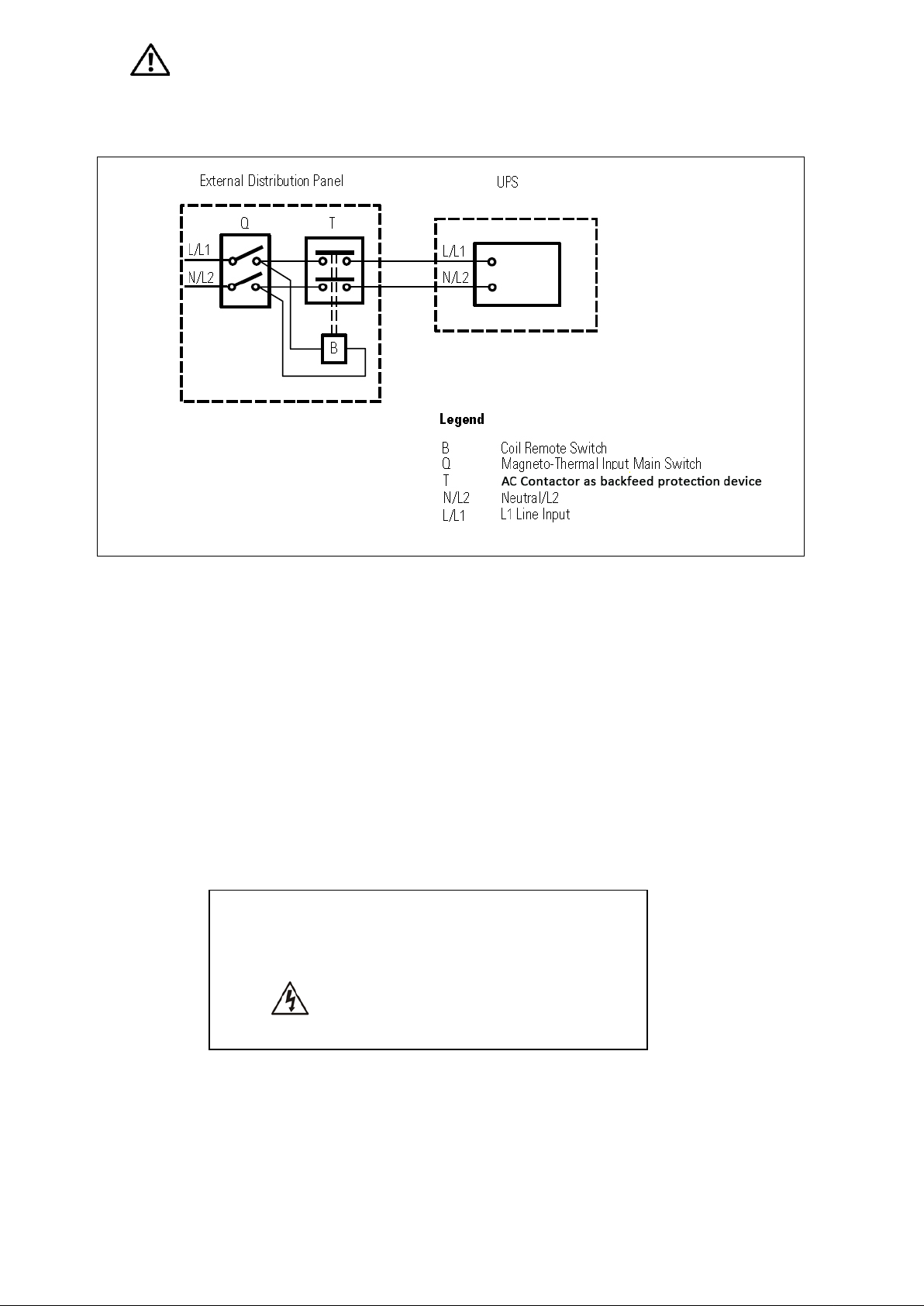
• There is no standard backfeed protection inside of the UPS. Please isolate the UPS before working
according to Diagram 1. The isolation device must be able to carry the UPS input current.
Diagram 1: External backfeed protection wiring
• This UPS should be connected with TN earthing system.
• The power supply for this uni t must be single-phase rated in accordance wi th the equipment nameplate.
It also must be suitably grounded.
• Use of this equipment in life support applications where failure of this equipment can reasonably be
expected to cause the failure of the life support equipment or to significantly affect its safety or
effectiveness is not recommended. Do not use this equipment in the presence of a flammable anesthetic
mixture with air, oxygen or nitrous oxide.
• Connect your UPS power module’s grounding terminal to a grounding electrode conductor.
• The UPS is connected to a DC energy source (battery). The out p ut terminals may be live when the UPS
is not connected to an AC supply.
- Isolate Uninterruptible Power System (UPS)
- Then check for Hazardous Voltage between all
terminals including the protective earth.
Risk of Voltage Backfeed
2
Page 6

1-5. Operation
* Safety
IEC/EN 62040-1
* EMI
Conducted Emission...............................:IEC/EN 62040-2
Category C3
Radiated Emission..................................:IEC/EN 62040-2
Category C3
*EMS
ESD.........................................................:IEC/EN 61000-4-2
Level 4
RS........................................................ ...:IEC/EN 61000-4-3
Level 3
EFT......................................................... :IEC/EN 61000-4-4
Level 4
SURGE................................................... :IEC/EN 61000-4-5
Level 4
CS........................................................... :IEC/EN 61000-4-6
Level 3
Power-frequency Magnetic field.............. :IEC/EN 61000-4-8
Level 4
Low Frequency Signals............................:IEC/EN 61000-2-2
tion in the
installation restrictions or additional measures may be
needed to prevent disturbances.
Do not disconnect the earth conductor cable on the UPS or the building wiring terminals in any
time since this would cancel the protective earth of the UPS system and of all connected loads.
The UPS system features its own, internal current source (batteries). The UPS output sockets or
output terminal blocks may be electrically live even if the UPS system is not connected to the building
wiring outlet.
In order to fully disconnect the UPS system, first press the “OFF” button and then disconnect the
mains.
Ensure that no liquid or other foreign objects can enter into the UPS system.
The UPS can be operated by any individuals with no previous experience.
1-6. Standards
Warning: This is a product for commercial and industrial applica
second environment-
3
Page 7
2. Installation and Operation
Model
Type
Model
Type
6K
6KL
10K
10KL
Emergency power off function connector (EPO
There are two different types of online UPS: standard and long-run models. Please refer to the following
model table.
standard model
Parallel function is also available for these two types and related installation and operation of Parallel
function will be described in detail in the following content.
Long-run model
2-1. Unpacking and Inspection
Unpack the package and check the package contents. The shipping package contains:
● One UPS
● One user manual
● One monitoring software CD
● One RS-232 cable (option)
● One USB cable
● One parallel cable (only available for parallel model)
● One share current cable (only available for parallel model)
● One battery cable (option)
NOTE: Before installation, please inspect the unit. Be sure that nothing inside the package is damaged
during transportation. Do not turn on the unit and notify the carrier and dealer immediately if there is any
damage or lacking of some parts. Please keep the original package in a safe place for future use.
2-2. Rear Panel View
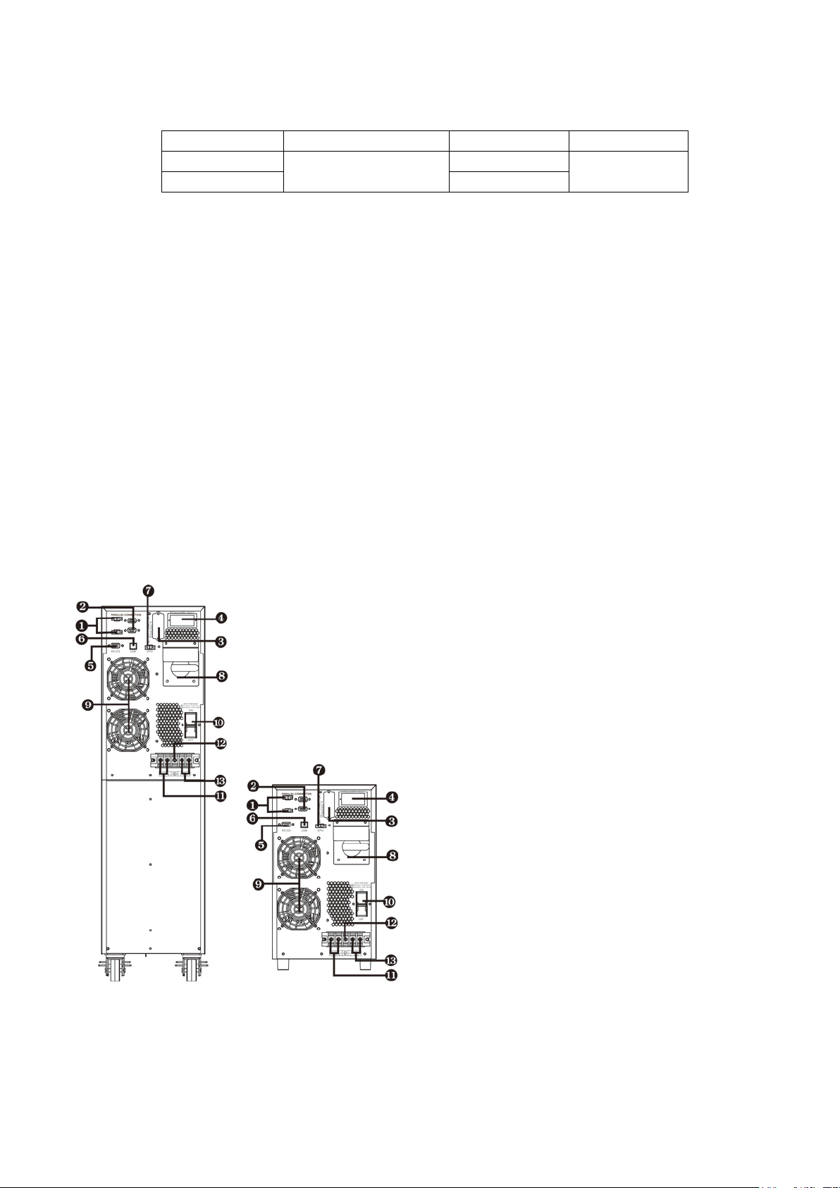
Diagram 1: 6K/10K Diagram 2: 6KL/10KL
Rear Panel Rear Panel
1) Share current port (only available for parallel model)
2) Parallel port (only available for parallel model)
3) External battery connector
4) Intelligent slot
5) RS-232 communication port
6) USB communication port
7)
connector)
8) Maintenance bypass switch
9) Cooling fan
10) Input cir cui t breaker
11) Output terminals
12) Ground
13) Input terminals
4
Page 8
2-3. Single UPS Installation
Wiring spec (AWG)
Input
Output
Battery
Ground
6K
10
10 10
6KL
10
10
10
10
10K 8 8 8
10KL 8 8 8 8
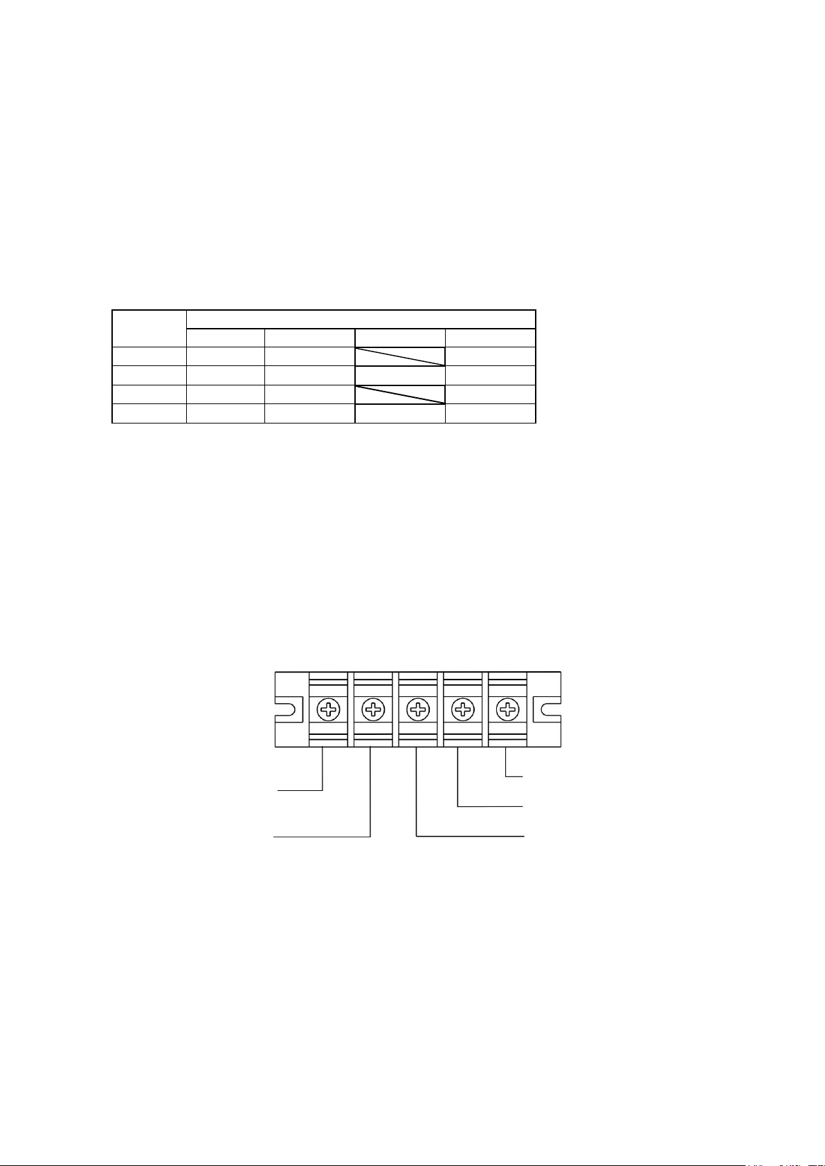
Input Neutral
Input Line
Ground
Output Line
Output Neutral
Installation and wiring must be performed in accordance with the local electric laws/regulations and execute
the following instructions by professional personnel.
1) Make sure the mains wire and breakers in the building are enough for the rated capacity of UPS to
avoid the hazards of electric shock or fire.
NOTE: Do not use the wall receptacle as the input power source for the UPS, as its rated current is less than
the UPS’s maximum input current. Otherwise the receptacle may be burned and destroyed.
2) Switch off the mains switch in the building before installation.
3) Turn off all the connected devices before connecting to the UPS.
4) Prepare wires based on the following table:
Model
NOTE 1: The cable for 6K/6KL should be able to withstand over 40A current. It is recommended to
use 10AWG or thicker wire for safety and efficiency.
NOTE 2: The cable for 10K/10KL should be able to withstand over 63A current. It is recommended to
use 8AWG or thicker wire for safety and efficiency.
NOTE 3: The selections for color of wires should be followed by the local electrical laws and
regulations.
5) Remove the terminal block cover on the rear panel of UPS. Then connect the wires according to the
following terminal block diagrams: (Connect the earth wire first when making wire connection. Disconnect
the earth wire last when making wire disconnection!)
Terminal Block wiring diagram
NOTE 1: Make sure that the wires are connected tightly with the terminals.
NOTE 2: Please install the output breaker between the output terminal and the load, and the breaker
should be qualified with leakage current protective function if necessary.
6) Put the terminal block cover back to the rear panel of the UPS.
5
Page 9

Warning: (Only for standard model)
● Make sure the UPS is not turned on before installation. The UPS should not be turned on during wiring
connection.
● Do not try to modify the standard model to the long-run model. Particularly, do not try to connect the
standard internal battery to the e xtern al ba ttery . T he b attery ty pe a nd volta ge m ay be di ffer ent. If yo u
connect them together, it maybe causes the hazard of electric shock or fire!
Warning: (Only for long-run model)
● Make sure a DC breaker or other protection device between UPS and external battery pack is installed. If
not, please install it carefully. Switch off the battery breaker before installation.
Warning:
● For standard battery pack, there is one DC breaker to disconnect the battery pack and the UP S . But for
other external battery pack, make sure a DC breaker or other protection device between UPS and
external battery pack is installed. If not, please install it carefully. Switch off the battery breaker before
installation.
NOTE: Set the battery pack breaker in “OFF” position and then install the battery pack.
● Pay highly attention to the rated battery voltage marked on the rear panel. If you want to change the
numbers of the battery pack, please make sure you modify the setting simultaneously. The connection
with wrong battery voltage may cause permanent damage of the UPS. Make sure the voltage of the
battery pack is correct.
● Pay highly attention to the polarity marking on external battery terminal block, and make sure the
correct battery polarity is connected. Wrong connection may cause permanent damage of the UPS.
● Make sure the protective earth ground wiring is correct. The wire current spec, color, position,
connection and conductance reliability should be checked carefully.
● Make sure the utility input & output wiring is correct. The wire current spec, color, position, connection
and conductance reliability should be checked carefully. Make sure the L/N site is correct, not reverse
and short-circuited.
2-4. UPS Installation for Parallel System
If the UPS is only available for single operation, you may skip this section to the next.
1) Install and wires the UPSs according to the section 2-3.
2) Connect the output wires of each UPS t o an output breaker.
3) Connect all output breakers to a major output breaker. Then this major output breaker will directly
connect to the loads.
4) Each UPS is connected to an independent battery pack.
5) Remove the cover of parallel share current cable port on the UP S, connect each UPS one by one with the
parallel cable and share current cable, and then screw the cover back again.
NOTE: The parallel system can not use one battery pack. Otherwise, it will cause system permanent failure.
6
Page 10
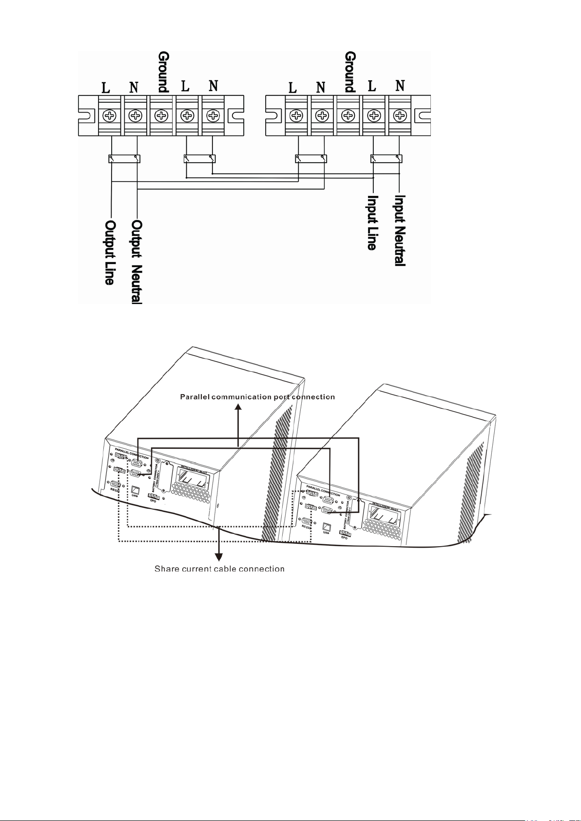
6) Refer to the following wiring diagram:
Diagram 1: Power cable connection
Diagram2: Wiring diagram of parallel system
2-5. Software Installation
For optimal computer system protection, install UPS monitoring software to fully configure UPS shutdown.
7
Page 11
3. Operations
Turn on the UPS: Press and hold the button more than 0.5s to turn on the UPS.
Turn off the UPS: Press and hold the button more than 0.5s to turn off the UPS.
Battery test: Press and hold the button more than 0.5s to test the battery while
UP key: Press this button to display next selection in setting menu.
Mute the alarm: Press and hold the button more than 0.5s to mute the buzzer.
Test/Up +
Mute/Down Button
Press and hold the two buttons simultaneous more than 1s to e nter/escape the
setting menu.
UPS Startup
● ● ●
●
No Output mode
○ ○ ○
○
Bypass mode
●
○ ○ ○
AC mode
○ ● ○
○
Battery mode
○
○ ● ○
○ ● ○
○
Battery Test
● ● ●
○
ECO mode
●
●
○
○
Fault
○ ○ ○
●
3-1. Button Operation
Button Function
ON/Enter Button
OFF/ESC Button
Test/Up Button
Mute/Down Button
* CVCF mode means converter mode.
Enter Key: Press this button to confirm the selection in setting menu.
Esc key: Press this button to return to last menu in setting menu.
in AC mode, or CVCF mode.
Please refer to section 3-4-9 for details.
Down key: Press this button to display previous selection in setting menu.
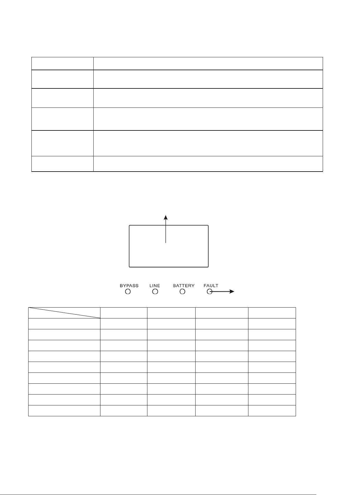
3-2. LED Indicators and LCD Panel
LCD panel
LED indicators
There are 4 LEDs on front panel to show the UPS working status:
Mode LED Bypass Line Battery Fault
CVCF mode
Note: ● means LED is lighting, and ○ means LED is faded.
8
Page 12
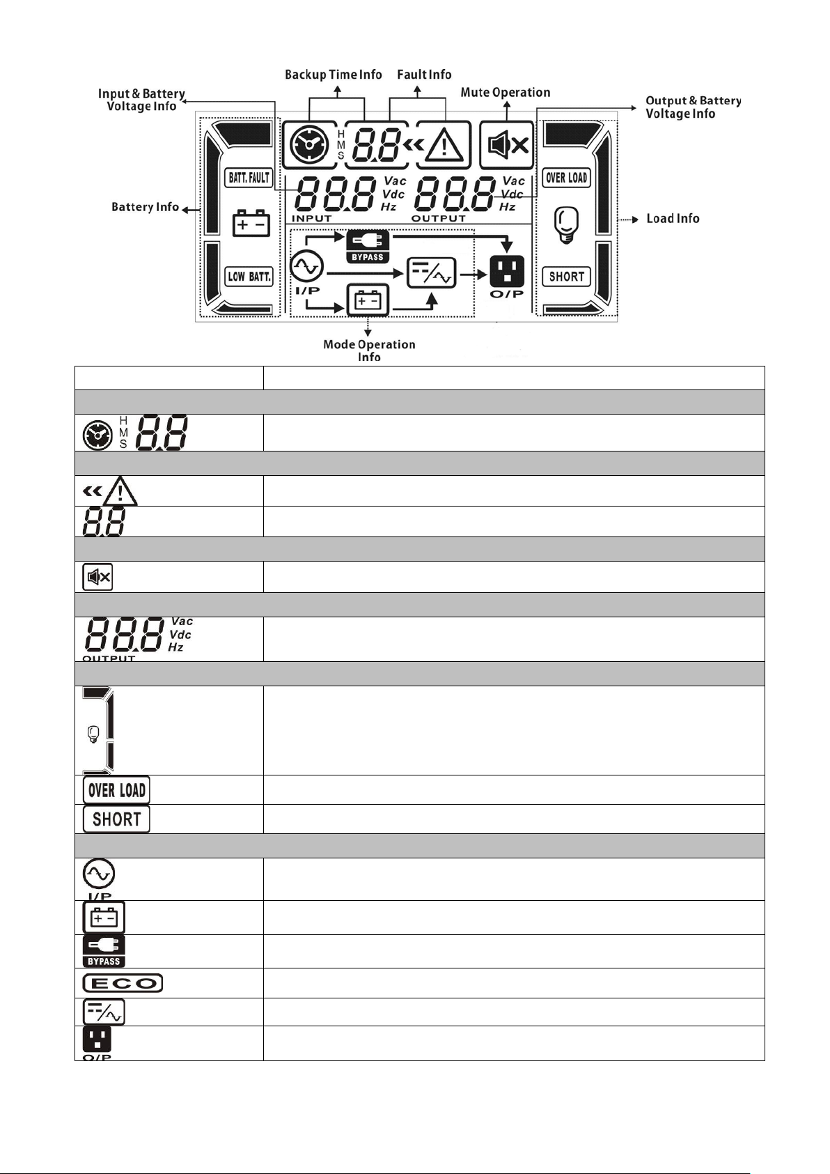
LCD Panel:
Display
Function
Backup time information
Indicates battery discharge time in numbers.
H: hours, M: minutes, S: seconds
Fault information
Indicates that the warning and fault occurs.
Indicates the fault codes, and the codes are listed in details in section 3-9.
Mute operation
Indicates that the UPS alarm is disabled.
Output & Battery voltage information
Indicates the output voltage, frequency or battery voltage.
Load information
Indicates the load level by 0-25%, 26-50%, 51-75%, and 76-100%.
Indicates overload.
Indicates the load or the output is short.
Mode operation information
Indicates the UPS connects to the mains.
Indicates the battery is working.
Indicates the bypass circuit is working.
Indicates the ECO mode is enabled.
Indicates the Inverter circuit is working.
Indicates the output is working.
Vac: output voltage, Vdc: battery voltage, Hz: frequency
9
Page 13
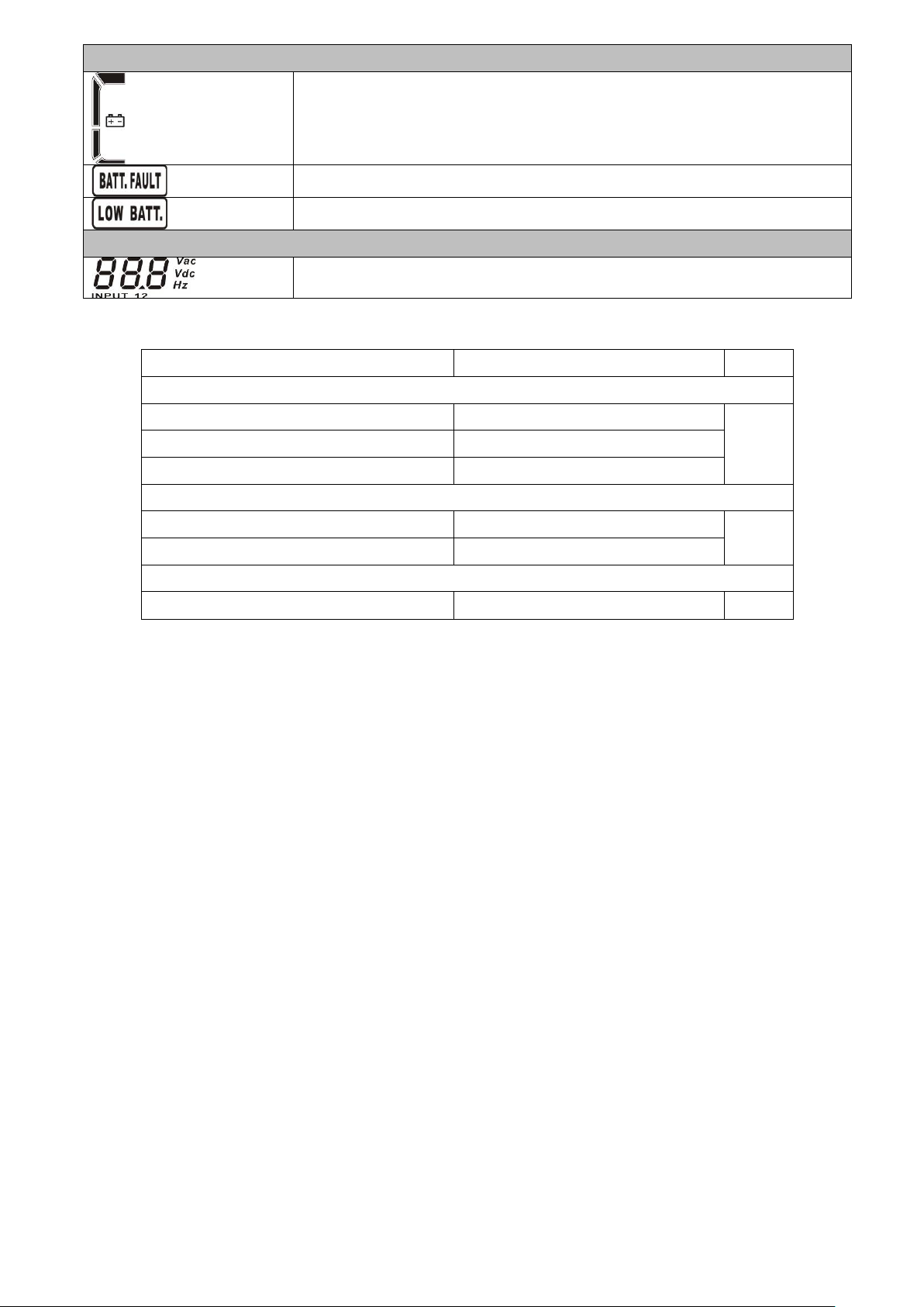
Battery information
Indicates the Battery capacity by 0-25%, 26-50%, 51-75%, and 76-100%.
Indicates the battery is not conne cted.
Indicates low battery level and low battery voltage.
Input & Battery voltage information
Indicates the input voltage or frequency or battery voltage.
Vac: Input voltage, Vdc: battery voltage, Hz: input frequency
3-3. Audible Alarm
Description
Buzzer status
Muted
UPS status
Bypass mode
Beeping once every 2 minutes
Battery mode
Beeping once every 4 seconds
Fault mode
Beeping continuously
Warning
Overload
Beeping twice every second
Others
Beeping once every second
Fault
Yes
Yes
Yes
All Beeping continuously
3-4. Single UPS Operation
3-4-1. Turn on the UPS with utility power supply (in AC mode)
1) After power supply is connected correctly, set the breaker of the battery pack at “ON” position (the
step only available for long-run model). Then set the input breaker at “ON” position. At this time
the fan is running and the UPS enter to power on mode f or initialization, several seconds later, UPS
operates in Bypass mode and supplies power to the loads via the bypass.
NOTE: When UPS is in Bypass mode, the output voltage will directly power from utility after you
switch on the input breaker. In Bypass mode, the load is not protected by UPS. To protect your
precious devices, you should turn on the UPS. Refer to next step.
2) Press and hold the “ON” button for 0.5s to turn on the UPS and the buzzer will beep once.
3) A few seconds later, the UPS will enter to AC mode. If the utility power is abnormal, the UPS will
operate in Battery mode without interruption.
NOTE: When the UPS is running out battery , it will shut down automatically at Battery mode. When the
utility power is restored, the UPS will auto restart in AC mode.
3-4-2. Turn on the UPS without utility power supply (in Battery mode)
1) Make sure that the breaker of the battery pack is at “ON” position (only for long-run model).
2) Press the “ON” button to set up the pow er supply for the UPS, UPS will enter to power on mode.
After initialization UPS will enter to No Output mode, then Press and hold the “ON” button for 0.5s
to turn on the UPS, and the buzzer will beep once.
3) A few seconds later, the UPS will be turned on and enter to Battery mode.
10
Page 14

3-4-3. Connect devices to UPS
After the UPS is turned on, you can connect devices to the UPS.
1) Turn on the UPS f irst and then switch on the devices one by one, the LCD panel will display total
load level.
2) If it is necessary to connect the inductive loads such as a printer, the in-rush current should be
calculated carefully to see if it meets the capacity of the UPS, because the power consumption of
this kind of loads is too big.
3) If the UPS is overload, the buzzer will beep twice every second.
4) When the UPS is overload, please remove some loads immediately. It is recommended to have the
total loads connected to the UPS less than 80% of its nominal power capacity to prevent overload
for system safety.
5) If the overload time is longer than acceptable time listed in spec at AC mode, the UPS will
automatically transfer to Bypass mode. After the overload is removed, it will return to AC mode. If
the overload time is longer than acceptable time listed in spec at Battery mode, the UPS will
become fault status. At this time, if bypass is enabled and the voltage and frequency in the r ange of
it is set value, the UPS will power to the load via bypass. If bypass function is disabled or the input
power is not within bypass acceptable range, it will cut off output directly.
3-4-4. Charge the batteries
1) After the UPS is connected to the utility power and working on the AC mode, the charger will charge
the batteries automatically except in Battery mode or during battery self-test.
2) Suggest to charge batteries at least 10 hours before use. Otherwise, the backup time may be
shorter than expected time.
3) Make sure the battery numbers setting on the control board (Please refer to the section 3-4-12 for
detailed setting) is consistent to real connection.
3-4-5. Battery mode operation
1) When the UPS is in Battery mode, the b uzzer will beep according to dif ferent battery c apacity . If the
battery capacity is more than 25%, the buzzer will beep once every 4 seconds; If the battery
voltage drops to the alarm level, the buzzer will beep quickly ( once every sec) to remind users that
the battery is at low level and the UPS will shut down automatically soon. Users could switch off
some non-critical loads to disable the shutdown alarm and prolong the backup time. If there is no
more load to be switched off at that time, you have to shut down all loads as soon as possible to
protect the devices or save data. Otherwise, there is a risk of data loss or load failure.
2) In Battery mode, if buzzer sound annoys, users can press the Mute button to disable the buzzer.
3) The backup time of the long-run model depends on the external battery capacity.
4) The backup time may vary from different environment temperature and load type.
5) When setting backup time for 16.5 hours (990min in LCD setting menu 09), after discharging 16.5
hours, UPS will shut down automatically to protect the battery. This battery discharge protection
can be enabled or disabled through LCD panel control. (Refer to 3-7 LCD setting section)
3-4-6. Test the batteries
1) If you need to check the battery status when the UPS is running in AC mode/CVCF mode/ECO mode,
you could press the “Test” button to let the UPS do battery self-test.
2) T o keep the system reliable, the UPS can perform the battery self-test periodically while connect the
11
Page 15

monitoring software.
3) Users also can set battery self-test through monitoring software.
4) If the UPS is at battery self-test, the LCD display and buzzer indication will be the same as at
Battery mode except that the battery LED is flashing.
3-4-7. Turn off the UPS with utility power supply in AC mode
1) Turn off the inverter of the UPS by pressing “OFF” button for at least 0.5s, and then the buzzer will
beep once. The UPS will turn into Bypass mode.
NOTE 1: If the UPS has been set to enable the bypass output, it will bypass voltage from utility
power to output terminal even though you have turned off the UPS (inverter).
NOTE 2: After turning off the UPS, please be aware that the UPS is working at Bypa ss mode and
there is risk of power loss for connected devices.
2) In Bypass mode, output voltage of the UPS is still present. In order to cut off the output, switch off
the input breaker. A few seconds later, there is no display shown on the display panel and UPS is
complete off.
3-4-8. Turn off the UPS without utility power supply in Battery mode
1) Turn off the UPS by pressing “OFF” button for at least 0.5s, and then the buzzer will beep once.
2) Then UPS will cut of f power to output and there is no display shown on the display panel.
3-4-9. Mute the buzzer
1) To mute the buzzer, please press the “Mute” button for at least 0.5s. If you press it again after t he
buzzer is muted, the buzzer will beep again.
2) Some warning alarms can’ t be muted unless the error is f ixed. Please refer to section 3-3 for the
details.
3-4-10. Operation in warning status
1) When Fault LED flashes and the buzzer beeps once every second, it means that there are some
problems for UPS operation. Users can get the warning code from LCD panel. Please check the 3-11
warning code table and the trouble shooting table in chapter 4 for details.
2) Some warning alarms can’t be muted unless the error is f ixed. Please refer to section 3-3 for the
details.
3-4-11. Operation in Fault mode
1) When Fault LED illuminates and the buzzer beeps continuously, it means that there is a fatal error in
the UPS. Users can get the fault code from display panel. Please check the 3-9 fault code table
and the trouble shooting table in chapter 4 for details.
2) Please check the loads, wiring, ventilation, utility, battery and so on after the fault occurs. Don’t try
to turn on the UPS again bef ore solving the proble ms. If the problems can’t be fixed, please contact
the distributor or service people immediately.
3) For emergency case, please cut off the connection from utility, external battery, and output
immediately to avoid more risk or danger.
3-4-12. Operation of changing battery numbers
1) This operation is only available for professional or qualified technicians.
2) Turn off the UPS. If the load couldn’t be cut off, you should remove the cover of maintenance
12
Page 16

bypass switch on the rear panel and turn the maintenance switch to “BPS” position first.
JP1
pin1 & pin2
pin3 & pin4
Pin5 & pin6
pin7 & pin8
Pin9 & pin10
16 X X 1 0 0 17 X X 0 1 1 18 X X 0 1 0 19 X X 0 0 1 20 X X 0 0
0
in series
voltage (V)
16
218
0 0 0 1 0
17
232
0 0 1 0 0
18
245
0 1 0 0 0
19
259
1 0 0 0 0
20
273
0 0 0 0 0
Charge current (A)
1A
0 0 1
3A
1 0 0
3) Switch off the input br eaker, and switch off the battery breaker (only ava ilable for long-run model).
4) Remove the cabinet cover and disconnect battery wire for standard model. Then, modify the
jumper on the control board to set the battery numbers as below table.
Battery Number
in series
Note: 0 = no jumper; 1 = connect with jumper; x = the pins are for other functions.
5) Modify the battery pack to meet the setting number in control board carefully.
6) Modify charger voltage according to below table to meet the setting number in control boar d. There
are 5 jumpers on the charger board. Please refer to the below table to modify charger voltage.
Battery Number
Charge
JP01 JP02 JP03 JP04 JP05
Note: 0 = no jumper; 1 = connect with jumper.
7) After complete the above steps, put the cover back, switch on the battery breaker for long-run
model and switch on the input breaker. Then, the UPS will enter Byp ass mode. If the UPS is in
maintenance Bypass mode, turn the maintenance switch to “UPS” position and then turn on the
UPS.
3-4-13. Operation of changing charging current:
1) This operation is only available for professional or qualified technicians.
2) Turn off the UPS. If the load couldn’t be cut off, you should remove the cover of maintenance
bypass switch on the rear panel and turn the maintenance switch to “BPS” position first.
3) Switch off the input breaker, and switch off the battery breaker (only available f or long-run model).
4) Remove the cabinet cover, and disconnect battery wire for standard model. Then modify the
jumpers on the charger board to set the charging current (refer to table below). Be careful that the
maximum charge current should not exceed the battery accepted charging current.
JP06 JP07 JP08
2A 0 1 0
4A 0 0 0
Note: 0 = no jumper; 1 = connect with jumper.
13
Page 17

3-5. Parallel Operation
3-5-1. Parallel system initial startup
First of all, please make sure all of the UPSs are parallel models and have the same configuration.
1) Turn on each UPS to AC mode respectively (Refer to section 3-4-1). Then, measure the output
voltage of each UPS to check if the voltage difference between actual output and setting value is
less than 1.5V (typical 1V) with multimeter. If the difference is more than 1.5V, please calibrate the
voltage by configuring inverter voltage adjustment (Refer to Program 15, section 3-7) in LCD
setting. If voltage difference remains more than 1.5V after calibration, please contact your local
distributor or service center for help.
2) Calibrate the output voltage measurement by configuring output voltage calibration (Refer t o
Program 16, section 3-7) in LCD setting to make sure the error between real output voltage and
detected value of UPS is less than 1V.
3) Turn off each UPS (Refer to section 3-4-7.). Then, follow the wiring procedure in section 2-4.
4) Remove the cover of parallel share current cable port on the UPS, connect each UPS one by one
with the parallel cable and share current cable, and then screw the cover back.
3-5-2. Turn on the parallel system in AC mode
1) Turn on the input breaker of each UPS. After all UPSs enter to bypass mode, measure the voltage
between output L1 of each UPS with multimeter. If the voltage difference is less than 1V, that
means all connections are correct. Otherwise, please check if the wirings are connected correctly.
2) Turn on the output breaker of each UPS. Before turning on each UPS in turns, check if PARXXX is
displayed in each UPS sequentially. If no “PARXXX” exists in any UPS, please check if the parallel
cables are connected correctly.
3) Turn on each UPS in turns. After a while, the UPSs will enter to AC mode synchronously and then,
the parallel system is completed.
3-5-3. Turn on the parallel system in Battery mode
1) Turn on the battery breaker (only available in long-run model) and output breaker of each UPS .
NOTE: It’s not allowed to share one battery pack for long-run UPSs in parallel system. Each UPS
should be connected to its battery pack.
2) Turn on any UPS. A few seconds later, the UPS will enter to battery mode.
3) Press the “ON” button to set up the power supply for another UPS, check if PARXXX is displayed. If
not, please check if the parallel cables are connected correctly. Then Turn on another UPS. A few
seconds later, the UPS will enter to battery mode and add to the parallel system.
4) If you have the third UP S, follow the same procedure of 3). Then, the parallel system is complete.
3-5-4. Add one new unit into the parallel system
1) Yo u can not add one new unit into t he par allel system whe n whole sy stem is runni ng. You must cut
off the load and shutdown the system.
2) Make sure all of the UPS are the parallel models, and follow the wiring refer to section 2-4.
3) Install the new parallel system refers to the previous section.
3-5-5. Remove one unit from the parallel system
There are two methods to remove one unit from the parallel system:
First method:
1) Press the “OFF” key twice and each time should last for more than 0.5s. Then, the UPS will enter
into bypass mode without output.
2) Turn off the output breaker of this unit, and then turn off the input breaker of this unit.
14
Page 18
3) After it shuts down, you can turn off the battery breaker (for long-run model) and remove the
BAT
Battery
parallel cable and share current cable. Then, remove the unit from the parallel system.
Second method:
1) If the bypass is abnormal, you can not remove the UPS without interruption. You must cut off the
load and shut down the system.
2) Make sure the bypass setting is enabled in each UPS and then turn of f the running syste m. All UPSs
will transfer to Bypass mode. Remove all the maintenance bypass covers and set the maintena nce
switches from “UPS” to “BPS”. Turn off the input breakers and battery breakers.
3) Remove the UPS that you want.
4) Turn on the input breaker of the remaining UPSs and the system will transfer to Bypass mode.
5) Set the maintenance switches from “BPS” to “UPS and put the ma intenance bypass covers back.
Turn on the remaining UPSs and finish the parallel system connection.
Warning: (Only for the parallel system)
● Before turning on the parallel system to activate inverter, make sure that all unit’s maintenance switch
at the same position.
● When parallel system is turned on to work through inverter, please do not operate the maintenance
switch of any unit.
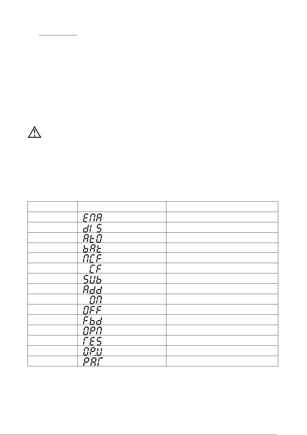
3-6. Abbreviation Meaning in LCD Display
Abbreviation Display content Meaning
ENA
DIS
ATO
NCF
CF
SUB
ADD
ON
OFF
FBD
OPN
Enable
Disable
Auto
Normal mode (not CVCF mode)
CVCF mode
Subtract
Add
On
Off
Not allowed
Allow
RES
OP.V
PAR
Reserved
Output voltage
Parallel
15
Page 19

3-7. LCD Setting
01
Output voltage
Y
03
Voltage range for bypass
Y
05
ECO mode enable/disable
Y
07
ECO mode frequency range setting
Y
09
Battery backup time setting
Y Y Y Y Y
Y
11
Reserved
Reserved for future
13
Battery voltage adjustment
Y Y Y Y Y
Y
15
Inverter voltage adjustment
Y Y Y
Interface
Setting
Parameter 3: Output voltage
Parameter 1
Parameter 2
Parameter 3
There are three parameters to set up the UPS. Refer to following diagram.
Parameter 1: It’s for program alternatives. There
are 16 programs to set up. Refer to below table.
Parameter 2 and parameter 3 are the setting
options or values for each program.
Programs available list for parameter 1:
Code Description
02 Output frequency Y
04 Frequency range for bypass Y
06 Voltage range for ECO mode Y
Bypass/
AC ECO CVCF Battery
No output
Battery
Test
08 Bypass mode setting Y Y
10 Reserved Reserved for future
12 Hot standby function enable/disable Y Y Y Y Y Y
14 Charger voltage adjustment Y Y Y Y Y Y
16 Output voltage calibration Y Y Y
*Y means that this program can be set in this mode.
Note: All parameter settings will be saved only when UPS shuts down normally with internal or external battery
connection. (Normal UPS shutdown means turning off input breaker in bypass mode).
01: Output voltage
You may choose the following output voltage in parameter 3:
208: Presents output voltage is 208Vac
220: Presents output voltage is 220Vac
230: Presents output voltage is 230Vac
240: Presents output voltage is 240Vac
16
Page 20

02: Output frequency
Interface
Setting
Parameter 2: Output Frequency
frequency.
Interface
Setting
Parameter 2: Set the acceptable low voltage for bypass. Setting
Interface
Setting
Parameter 2: Set the acceptable low frequency for bypass.
The default value is 54.0Hz/64.0Hz.
60 Hz, CVCF mode
50 Hz, Normal mode
ATO
Setting the output frequency. You may choose following three
options in parameter 2:
50.0Hz: The output frequency is setting for 50.0Hz.
60.0Hz: The output frequency is setting for 60.0Hz.
ATO: If selected, output frequency will be decided according to
the latest normal utility frequency. If it is from 46Hz to 54Hz, the
output frequency will be 50.0Hz. If it is from 56Hz to 64Hz, the
output frequency will be 60.0Hz. ATO is default setting.
Parameter 3: Frequency mode
Setting output frequency at CVCF mode or not CVCF mode. You
may choose following two options in parameter 3:
CF: Setting UPS to CVCF mode. If selected, the output frequency
will be fixed at 50Hz or 60Hz according to setting in parameter 2.
The input frequency could be from 46Hz to 64Hz.
NCF: Setting UPS to normal mode (not CVCF mode). If selected,
the output frequency will synchronize with the inp ut frequency
within 46~54 Hz at 50Hz or within 56~64 Hz at 60Hz accordin g to
setting in parameter 2. If 50 Hz selected in parameter 2, UPS will
transfer to battery mode when input frequency is not within
46~54 Hz. If 60Hz selected in parameter 2, UPS will transfer to
battery mode when input frequency is not within 56~64 Hz.
*If Parameter 2 is ATO, the Parameter 3 will show the current
Note: If the UPS is set to CVCF mode, the bypass function will be disabled automatically .
But when a single UPS without parallel function is powered on with mains and before th e UPS
finished the startup, there will be a few seconds of voltage pulse (same as the inp u t voltage)
on the bypass output.
If you need to remove the pulse on this mode to protect your load better, you could contact the
dealer for help.
For the UPS with parallel function, this pulse situation won’t happen.
03: Voltage range for bypass
04: Frequency range for bypass
range is from 110V to 209V and the default value is 110V.
Parameter 3: S et the acceptable high voltage for bypass. Setting
range is from 231V to 276V and the default value is 264V.
50 Hz system: Setting range is from 46.0Hz to 49.0Hz.
60 Hz system: Setting range is from 56.0Hz to 59.0Hz.
The default value is 46.0Hz/56.0Hz.
Parameter 3: Set the acceptable high frequency for bypass.
50 Hz: Setting range is from 51.0Hz to 54.0 Hz.
60 Hz: Setting range is from 61.0Hz to 64.0Hz.
17
Page 21

05: ECO mode enable/disable
Interface
Setting
Parameter 3: Enable or disable ECO function. You may choose
function is enabled.
Interface
Setting
Parameter 2: Low voltage point in ECO mode. The setting range
Interface
Setting
Parameter 2: Set low frequency point for ECO mode.
The default value is 52.0Hz/62.0Hz.
Parameter 2:
mode.
Interface
Setting
Parameter 3:
following two options:
DIS: disable ECO function
ENA: enable ECO function
If ECO function is disabled, vol tage range and freq uency range for
ECO mode still can be set, but it is meaningless unless the ECO
06: Voltage range for ECO mode
is from 5% to 10% of the nominal voltage.
Parameter 3: High voltage point in ECO mode. The setting range
is from 5% to 10% of the nominal voltage.
07: Frequency range for ECO mode
50 Hz system: Setting range is from 46.0Hz to 48.0Hz.
60 Hz system: Setting range is from 56.0Hz to 58.0Hz.
The default value is 48.0Hz/58.0Hz.
Parameter 3: Set high frequency point for ECO mode.
50 Hz: Setting range is from 52.0Hz to 54.0 Hz.
60 Hz: Setting range is from 62.0Hz to 64.0Hz.
08: Bypass mode setting
Interface Setting
OPN: Bypass allowed. When selected, UPS will run at Bypass
mode depending on bypass enabled/disabled setting.
FBD: Bypass not allowed. When selected, it’s not allowed for
running in Bypass mode under any situations.
Parameter 3:
ENA: Bypass enabled. When selected, Bypass mode is activated.
DIS: Bypass disabled. When selected, automatic bypass is
acceptable, but manual bypass is not allowed. Manual byp ass
means users manually operate UPS for Bypass mode. For
example, pressing OFF button in AC mode to turn into Bypass
09: Battery backup time setting
000~999: Set the maximum backup time from 0min to 999min.
UPS will shut down to protect battery after backup time arrives.
DIS: Disable battery discharge protection and backup time will
depend on battery capacity.
The default value is DIS.
18
Page 22

10: Reserved
Interface
Setting
Reserved
Interface
Setting
Reserved
Parameter 2: HS.H
normal mode and can’t restart without battery
Parameter 2: Select “Add” or “Sub” function to adjust battery
Interface
Setting
Parameter 2: you may choose Add or Sub to adjust charger
modification should be suitable to battery specifications.
11: Reserved
12: Hot standby function enable/disable
Interface Setting
Enable or disable Hot standby function. You may choose following
two options in Parameter 3:
YES: Hot standby function is enabled. It means that the current
UPS is set to host of the hot standby function, and it will restart
after AC recovery even without battery connected.
NO: Hot standby function is disabled. The UPS is running at
13: Battery voltage adjustment
Interface Setting
voltage to real figure.
Parameter 3: the voltage range is from 0V to 5.7V, the default
value is 0V.
14: Charger voltage adjustment
voltage
Parameter 3: the voltage range is from 0V to 9.9V, the default
value is 0V.
NOTE:
*Before making voltage adjustment, be sure to disconnect all
batteries first to get the accurate charger voltage.
*We strongly suggest to use the default value (0). Any
19
Page 23

15: Inverter voltage adjustment
Interface
Setting
Parameter 2: you may choose Add or Sub to adjust inverter
Interface
Setting
Parameter 2: it always shows OP.V as output voltage.
nal measurement value of the
according to the measurement from an external voltage meter.
. The
used for parallel operation.
Operating mode/status
voltage
Parameter 3: the voltage range is from 0V to 6.4V, the default
value is 0V.
16: Output voltage calibration
When the output voltage can not be detected(less than 50VAC),
this menu will be reserved, “
2 and parameter 3.
Parameter 3: it shows the inter
output voltage, and you can calibrate it by pressing Up or Down
The calibration result will be effective by pressing Enter
calibration range is limited within +/-9V. This function is normally
” will be displayed in parameter
3-8. Operating Mode/Status Description
If parallel UPS systems are successfully set up, it will show one more screen with “PAR” in parameter 2 and
be assigned number in parameter 3 as below parallel screen diagram. The master UPS will be default
assigned as “001” and slave UPSs will be assigned as either “002” or “003”. The assigned numbers may be
changed dynamically in the operation;
AC mode Description When the input voltage is within acceptable ra nge, UPS will pro vide p ure
and stable AC power to output. The UPS will also charge the battery at
AC mode.
LCD display
20
Page 24

ECO mode Description When the input voltage is within voltage regula tion r ange and EC O mode
is enabled, UPS will bypass voltage to output for energy saving.
The UPS will still charge
battery under this mode.
UPS will backup power from battery and alarm will beep every 4 seconds.
minutes.
he line
is used to check the battery status.
t messages in LCD
panel.
LCD display
CVCF mode Description When input frequency is within 46 to 64Hz, the UPS can be set at a
constant output frequency, 50 Hz or 60 Hz.
LCD display
Battery mode Description When the input voltage is bey ond the accep table range or power failure,
LCD display
Bypass mode Description When input voltage is within acceptable range and bypass is enabled,
turn off the UPS and it will enter Bypass mode. Alarm beeps every two
LCD display
Battery Test Description When UPS is in AC mode or CVCF mode, press “Test” key for more than
0.5s. Then the UPS will beep once and start “Battery Test”. T
between I/P and inverter icons will blink to remind users. This operation
LCD display
Fault status Description When UPS has fault happened, it will display faul
21
Page 25

3-9. Fault Code
Fault event
Fault code
Icon
Fault event
Fault code
Icon
Bus start failure
01
None
Battery SCR short circuited
21
None
Bus over
02
None
Inverter relay short circuited
24
None
Bus under
03
None
Charger short circuited
2a
None
Bus unbalance
04
None
Can communication fault
31
None
Inverter soft start failure
11
None
Parallel output current
unbalance
36
None
High Inverter voltage
12
None
Over temperature
41
None
Low Inverter voltage
13
None
CPU communication failure
42
None
Inverter output short circuited
14
Overload
43
Negative power fault
1A
None
Battery turn-on failure
6A
None
Inverter over current
60
None
PFC current failure in battery
mode
6B
None
Inverter waveform abnormal
63
None
Bus voltage changes too fast
6C
None
Warning
Icon (flashing)
Alarm
Overload
Beeping twice every second
I/P fuse broken
Beeping every second
LCD display
3-10. Warning Indicator
Battery low
Battery unconnected
Over charge
EPO enable
Fan failure/Over temperature
Charger failure
Beeping every second
Beeping every second
Beeping every second
Beeping every second
Beeping every second
Beeping every second
Overload 3 times in 30min
Beeping every second
22
Page 26

3-11 Warning Code
Warning code
Warning event
Warning code
Warning event
01
Battery unconnected
10
L1 IP fuse broken
Line situations are different in parallel
system
Bypass situations are different in
parallel system
Locked in bypass after overload 3
times in 30min
0A
Fan failure
3A
Cover of maintain switch is open
0B
EPO enable
3D
Bypass unstable
0E
Charger failure
07 Over charge 21
08 Low battery 22
09 Overload 33
0D Over temperature
3E Boot loader is missing
23
Page 27

4. Trouble Shooting
Symptom
Possible cause
Remedy
No indication and alarm in the front
normal.
The AC input power is not
and the warning code
flash on LCD display and alarm
beeps every second.
Set the circuit in closed
position to disable EPO
flash on
second.
The external or internal
battery is incorrectly
Check if all batteries are
flash on
LCD display and alarm beeps twice
Remove excess loads from UPS
output.
UPS is overloaded. Devices
connected to the UPS are fed
directly by the electrical
network via the Bypass.
After repetitive overloads, the
UPS is locked in the Bypass
mode. Connected devices are
fed directly by the mains.
output first. Then shut down
Fault code is shown as 43. The icon
lights on LCD display and
alarm beeps continuously.
UPS is overload too long and
Fault code is shown as 14, the icon
n LCD display, and
The UPS shut down
automatically because short
circuit occurs on the UPS
output.
Check output wiring and if
on LCD display and alarm
A UPS internal fault has
occurred. There are two
directly from AC power via
2. The load is no longer
supplied by power.
Battery backup time is shorter than
Charge the batteries for at
hours and then check
capacity. If the problem still
persists, consult your dealer.
Contact your dealer to replace
the battery.
Fan is locked or not working;
high.
If the UPS system does not operate correctly, please solve the problem by using the table below.
display panel even thou gh the mains is
The icon
The icon and
LCD display and alarm beeps every
The icon and
every second.
connected well.
EPO function is enabled.
connected.
UPS is overload.
becomes fault. Then UPS shut
down automatically.
Check if input cable firmly
connected to the mains.
function.
connected well.
Remove excess loads from UPS
output.
Remove excess loads from UPS
the UPS and restart it.
Remove excess loads from UPS
output and restart it.
lights o
alarm beeps continuously.
Fault code is shown as 01, 02, 03, 04,
11, 12, 13, 14,1A, 21 , 24, 35, 36, 41,
42 or 43
beeps continuously.
nominal value
The icon and flash on LCD
display and alarm beeps every second.
possible results:
1. The load is still supplied, but
bypass.
Batteries are not fully charged
Batteries defect
or the UPS tempe rature is too
connected devices are in short
circuit status.
Contact your dealer.
least 7
Check fans and notify dealer.
24
Page 28

5. Storage and Maintenance
-25°C - 40°C
Every 3 months
1-2 hours
40°C - 45°C
Every 2 months
1-2 hours
5-1. Storage
Before storing, charge the UPS at least 7 hours. Store the UPS covered and upright in a cool, dry
location. During storage, recharge the battery in accordance with the following table:
Storage Temperature Recharge Frequency Charging Duration
5-2. Maintenance
The UPS system operates with hazardous voltages. Repairs may be carried out only by qualified
maintenance personnel.
Even after the unit is disconnected from the mains, components inside the UPS system are still
connected to the battery packs which are potentially dangerous.
Before carrying out any kind of service and/or maintenance, disconnect the batteries and v erify that
no current is present and no hazar dous v oltage exists in the terminals of high capabilit y capacitor such as
BUS-capacitors.
Only persons are adequately familiar with batteries and with the required precautionary measures
may replace batteries and supervise operations. Unauthorized persons must be kept well away from the
batteries.
Verify that no voltage between the battery ter minals and the ground is present before mainten ance
or repair. In this product, the battery circuit is not isolated from the input voltage. Hazardous voltages may
occur between the battery terminals and the ground.
Batteries may cause electric shock and have a high short-circuit current. Please remove all
wristwatches, rings and other metal personal objects before maintenance or repair, and only use tools
with insulated grips and handles for maintaining or repairing.
When replace the batteries, install the same number and same type of batteries.
Do not attempt to dispose of batteries by burning them. This could cause battery explosion. The
batteries must be rightly deposed according to local regulation.
Do not open or destroy batteries. Escaping electrolyte can cause injury to the skin and eyes. It may
be toxic.
Please replace the fuse only with the same type and amperage in order to avoid fire hazards.
Do not disassemble the UPS system.
25
Page 29

6. Specifications
MODEL
VFI 6000 CG PF1
VFI 10000 CG PF1
CAPACITY*
6000 VA / 6000 W
10000 VA / 10000 W
INPUT
110~300Vac @ (0~60%) Load
176~300Vac @(80~100%)Load
Low Line Comeback
Low Line Loss Voltage + 10V
High Line Comeback
High Line Loss Voltage - 10V
46Hz ~ 54 Hz @ 50Hz system
56Hz ~ 64 Hz @ 60Hz system
Phase
Single phase with ground
Power Factor
0.99 at 100% Load
OUTPUT
Output voltage
208/220/230/240VAC
AC Voltage Regulation
± 1%
Frequency Range
(Synchronized Range)
46Hz ~ 54 Hz @ 50Hz system
56Hz ~ 64 Hz @ 60Hz system
Frequency Range (Batt. Mode)
50 Hz ± 0.1 Hz or 60Hz ± 0.1 Hz
100%~110%: 10min ; 110%~130%: 1min ; >130% : 1sec
Current Crest Ratio
3:1 max
Line Battery
0 ms
Inverter Bypass
0 ms
Inverter ECO
<10 ms
EFFICIENCY
AC mode
> 94%
Battery Mode
> 93%
BATTERY
Type
12 V / 9 Ah
12 V / 9 Ah
Numbers
16
20
Charging Current
1 A ± 10% (max.)
Charging Voltage
(Battery number*13.65 V) ± 1%
PHYSICAL
Dimension, DXWXH(mm)
369 x 190 x 688
442 x 190 x 688
Net Weight (kgs)
57
67
ENVIRONMENT
Operation Temperature
0 ~ 40°C (the battery life will down when > 25°C)
Operation Humidity
<95 % and non-condensing
Operation Altitude**
<1000m
Acoustic Noise Level
Less than 55dB @ 1 Meter
Less than 58dB @ 1 Meter
MANAGEMENT
Smart RS-232 or USB
Supports Windows® 2000/2003/XP/Vista/2008/7/8, Linux, Unix, and MAC
Optional SNMP
Power management from SNMP manager and web browser
Line Loss
Voltage Range
Frequency Range
AC mode
Overload
Battery mode 100%~110%: 30sec ; 110%~130%: 10sec ; >130% : 1sec
Harmonic Distortion ≦ 1 % @ 100% Linear Load; ≦ 4 % @ 100% Non-linear Load
Transfer Time
140~300V @ (60~80%) Load
≧
Recharge Time 9 hours recover to 90% capacity
* De-rate capacity to 60% of capacity in CVC F mode and to 90% when the output voltage is adjusted to 208VAC.
**If the UPS is installed or used in a place where the altitude is above than 1000m, the output power must be de-rated one percent per 100m.
***Product specifications are sub ject to change without further n otice.
26
Page 30

PowerWalker
VFI 6000 CG PF1
VFI 10000 CG PF1
Bedienungsanleitung
DE
Version: 1.1
Page 31

Sicherheitshinweise und die
Alle Warnungen und Bedienungshinweise in
dieser Anleitung müssen unbedingt beachtet
werden. Bewahren sie diese Anleitung gut auf
und lesen Sie die folgenden Hinweise vor der
Installation sorgfältig durch. Nehmen Sie das
Gerät erst in Betrieb, wenn Sie alle
Bedienungsanleitung sorgfältig durchgelesen
haben.
Page 32

Inhaltsverzeichnis
1. SICHERHEIT UND EMV-HINWEISE ........................................................................................................................ 1
1-1. TRANSPORT UND LAGERUNG ................................................................................................................................. 1
1-2. VORBEREITUNG ............................................................................................................................................................. 1
1-3. INSTALLATION ............................................................................................................................................................... 1
1-4. ANSCHLUSS W ARNHINWEISE .............................................................................................................................. 2
1-5. BETRIEB ........................................................................................................................................................................ 3
1-6. STANDARDS ................................................................................................................................................................... 3
2. INSTALLATION UND BETRIEB ................................................................................................................................. 4
2-1. AUSPACKEN UND ÜBERPRÜFEN ............................................................................................................................. 4
2-2. HINTERE KONSOLENANSICHT ............................................................................................................................. 4
2-3. USV EINZELINSTALLATION ..................................................................................................................................... 5
2-4. USV INSTALLATION FÜR PARALLELSYSTEM ......................................................................................................... 6
2-5. SOFTWARE INSTALLATION .............................................................................................................................................. 7
3. BEDIENUNG .................................................................................................................................................................... 8
3-1. TASTENBEDIENUNG ................................................................................................................................................. 8
3-2. LED ANZEIGEN UND LCD ANZEIGE ........................................................................................................................ 8
3-3. AKKUSTISCHER ALARM .......................................................................................................................................... 10
3-4.
USV EINZELBETRIEB
3-5.
PARALLEL BETRIEB
3-6. LCD-ANZEIGE INDEX DER FORMULIERUNGEN ............................................................................................................ 15
3-7. LCD EINSTELLUNG ................................................................................................................................................. 17
3-8.
BETRIEBSMODUS
3-9.
FEHLERCODE
3-10.
WARNANZEIGE
3-11
WARNCODE
4. FEHLERBEHEBUNG ..................................................................................................................................................... 26
5. LAGERUNG UND INSTANDHALTUNG ................................................................................................................... 27
5-1.
LAGERUNG
............................................................................................................................................................... 24
................................................................................................................................................................. 27
.................................................................................................................................................. 10
...................................................................................................................................................... 14
/ZUSTANDSBESCHREIBUNG
....................................................................................................................................................... 24
.............................................................................................................................................................. 25
.......................................................................................................... 22
5-2.
WARTUNG
6. SPEZIFIKATIONEN ..................................................................................................................................................... 28
.................................................................................................................................................................. 27
Page 33

1. Sicherheits- und EMC Hinweise
Bitte lesen Sie die folgenden Sicherheitshinweise und die Bedienungsanleitung vor der Installation und
Erstbenutzung aufmerksam durch!
1-1. Transport und Lagerung
Bitte transportieren Sie das USV-System nur in der Original verpackung, um es vo r Schlägen und
Stößen zu schützen.
Die USV muss in einem trockenen und gut belüfteten Raum aufbewahrt werden.
1-2. Vorbereitung
Wenn das USV-System aus einer kalten Umgebung in den Betriebsraum gebracht wird, kann
eine Kondensation auftreten. Das USV-System muss vor der Inbetriebnahme absolut trocken sein.
Betreiben Sie das Gerät erst nach einer Akklimatisierungszeit von mindestens 2 Std.
Betreiben Sie das Gerät nicht in der Nähe von Wasser oder in einer feuchten Umgebung.
Stellen Sie das USV-System nicht in der Nähe von Wärmequellen auf oder setzen Sie es nicht
direkter Sonneneinstrahlung aus.
Halten Sie die Ventilationsöffnungen des USV-Gehäuses frei.
1-3. Installation
Schließen Sie keine Geräte an die Ausgang-Buchse oder Klemmen an, die Die USV überlasten
(z.B. Geräte hoher Leistung).
Platzieren Sie das Kabel so, dass niemand darauf treten oder darüber stolpern kann.
Halten Sie die Ventilationsöffnungen des USV-Gehäuses frei. Die USV muss an einem Ort mit
guter Belüftung installiert werden. Achten Sie auf ausreichend Platz für die Belüftung.
Die USV ist mit Erdungsklemmen im Endkonfigurations-System ausgestattet, mit
Potenzialausgleich zur externen USV-Batteriebox.
Die USV darf nur von qualifiziertem Fachpersonal installiert werden.
Für den Kurzschlussschutz sind bauseits Sicherungen und Lasttrennschalter erforderlich.
Eine integrierte Notvorrichtung welche verhindert, dass die Spannung zu hoch wird, sollte
vorgesehen sein.
Vor dem Anschluss des Gerätes an die Stromversorgung, zuerst die Erdung anschließen.
Die Installation und Verdrahtung ist gemäß den geltenden Bestimmungen unter Beachtung der
örtlichen Vorschriften durchzuführen.
1
Page 34

1-4. Anschluss Warnhinweise
Vor dem Betrieb
• Innerhalb gibt es keinen Standard-Nachspeiseschutz, bitte isolieren Sie die USV vor dem Betrieb
entsprechend. Die Trennvorrichtung muss in der Lage sein, den USV-Eingangsstrom zu führen.
Diagramm 1: Externe Nachspeise-Schutzverdrahtung
• Diese USV sollte an ein TN Erdungssystem angeschlossen werden.
• Die Stromversorgung für dieses Gerät muss gemäß Typenschild einphasig bewertet werden. Es muss
auch in geeigneter Weise geerdet werden.
• Die Nutzung dieses Geräts in lebenserhaltenden Anwendungen, denen ein Ausfall dieses Gerätes
zugemutet wird, kann dazu führen, dass diese Geräte versagen oder deren Sicherheit oder Wirksamkeit
beeinträchtigt wird. Verwenden Sie dieses Gerät nicht in der Nähe von einer brennbaren Mischung von
Anästhetika mit Luft, Sauerstoff oder Stickstoffoxid.
• Verbinden Sie Ihren USV-Erdungsanschluss des Leistungsmoduls mit einem Erdungsleiter.
• Die USV ist mit einer DC-Energiequelle (Batterie) verbunden. Die Ausgangsklemmen können
stromführend sein, selbst, wenn die USV nicht an ein Stromnetz angeschlossen ist.
- Unterbrechungsfreie Stromversorgung isolieren (USV)
- Prüfen Sie dann auf gefährliche Spannung zwischen
allen Anschlüssen, einschließlich der Schutzerdung.
Gefahr von Spannungsnachspeise
2
Page 35

1-5. Operation
* Sicherheit
IEC/EN 62040-1
* EMI
Leitungsgeführte Emissionen......................... :IEC/EN 62040-2
Kategorie C3
Emittierte Strahlung...................................... :IEC/EN 62040-2
Kategorie C3
*EMS
ESD......................................................... :IEC/EN 61000-4-2
Level 4
RS.............................................................:IEC/EN 61000-4-3
Level 3
EFT.......................................................... :IEC/EN 61000-4-4
Level 4
Überspannung......................................... :IEC/EN 61000-4-5
Level 4
CS........................................................... :IEC/EN 61000-4-6
Level 3
Netzfrequenz Magnetfeld…………................ :IEC/EN 61000-4-8
Level 4
Niederfrequenz Signale...............................:IEC/EN 61000-2-2
Maßnahmen erforderlich sein.
Das Erdungskabel während des Betriebs nicht von der USV-Anlage abziehen, da sonst die
Schutzerdung der USV-Anlage und aller angeschlossenen Verbraucher aufgehoben wird.
Das USV-System verfügt über eine eigene, interne Stromquelle (Batterien). Die USV
-Ausgangssteckdosen oder Ausgangsklemmen können stromführend sein, auch wenn die USV nicht an
die Steckdose bzw. an die Einspeisung der Hausinstallation angeschlossen ist.
Zum völligen Abschalten der USV die „OFF“-Taste drücken und dann das Netzkabel
herausziehen.
Stellen Sie sicher, dass keine Flüssigkeit oder sonstige Fremdkörper in die USV gelangen.
Die USV kann von allen Personen, ohne Vorkenntnisse, bedient werden.
1-6. Standards
Warnung: Dieses Produkt ist zur industriellen und kommerziellen Nutzung in
der zweiten Umwelt-Installationsbeschränkung oder es können zusätzliche
3
Page 36

2. Installation und Betrieb
Modell
Typ
Modell
Typ
6K
6KL
Modell
10K
10KL
Es gibt zwei unterschiedliche Arten von Online-USV: Standard und Long-run Modelle. Bitte beachten Sie
folgende Modellübersicht.
Standardmodell
Optional bieten wir auf Anfrage für diese Typen auch eine “Parallel-Funktion” an. Die USV mit
Parallel-Funktion wird “Parallel-Modell ” genannt. Die Installation und der Betrieb werden im folgenden
Kapitel ausführlich beschrieben.
Long-run
2-1. Auspacken und Überprüfen
Packen Sie den Inhalt aus und überprüfen Sie den Packungsinhalt. Das Paket enthält:
● Eine USV
● Eine Bedienungsanleitung
● Eine Monitoring Software CD
● Ein RS-232 Kabel (optional)
● Ein USB-Kabel
● Ein Parallelkabel (nur für das Parallel-Modell verfügbar)
● Ein Stromkabel (nur für das Parallel-Modell verfügbar)
● Ein Batteriekabel (optional)
HINWEIS: Inspizieren Sie das Gerät vor der Installation. Vergewissern Sie sich, dass kein Teil in der
Packung während des Transport beschädigt wurde. Falls ein Teil fehlt oder schadhaft ist, schalten Sie die
Einheit nicht ein und informieren Sie den Transporteur und Händler. Bitte bewahren Sie die
Original-Verpackung für weiteren Gebrauch auf.
2-2. HINTERE KONSOLENANSICHT
1) Geteilte Schnittstelle (nur für das Parallel-Modell
verfügbar)
2) Parallel-P ort (nur für das Parallel-Modell verfügbar)
3) Externer Batterieanschluss
4) Intelligent Slot
5) RS-232 Kommunikationsschnittstelle
6) USB Kommunikationsschnittstelle
7) Stecker für Not-Aus-Schalter (EPO Verbinder)
8) Wartungs-Bypass-Schalter
9) Lüfter
10) Eingangsschutzschalter
11) Ausgangsterminal
12) Erdung
13) Eingangsterminal
Diagramm 1: 6K/10K Diagramm 2: 6KL/10KL
Rückseite Rückseite
4
Page 37

2-3. USV Einzelinstallation
Verdrahtung spec (AWG)
Input
Ausgang
Batterie
Erdung
6K
10
10 10
6KL
10
10
10
10
10K 8 8 8
10KL 8 8 8 8
Eingang Neutral
Eingangsleitung
Erdung
Ausgangsleitung
Ausgang Neutral
Die Installation und Verdrahtung ist gemäß den geltenden Bestimmungen unter Beachtung der örtlichen
Vorschriften von einem Fachmann durchzuführen.
1) Stellen Sie sicher, dass die Nennleistung des Netzkabels und der Schalter ausreichend sind, um
Stromschlägen und Brandgefahr vorzubeugen.
HINWEIS: Schließen Sie die USV nicht an die Wandsteckdose an, wenn die Nennleistung geringer ist, als
der maximale Eingangsstrom der USV. Andernfalls kann die Steckdose durchbrennen und zerstört werden.
2) Schalten Sie vor der Installation den Netzschalter aus.
3) Schalten Sie alle Geräte vor dem Anschluss an die USV aus.
4) Bereiten Sie die Verdrahtung gemäß nachfolgender Tabelle vor:
Modell
HINWEIS 1: Das Kabel für 6K/6KL sollte einer Spannung von 40 A standhalten. Es wird ein
Phasenkabel von AWG10 oder dicker empfohlen für Sicherheit und Effizienz.
HINWEIS 2: Das Kabel für 10K/10KL sollte einer Spannung von 63A standhalten. Es wird ein
Phasenkabel von 8AWG oder dicker empfohlen für Sicherheit und Effizienz.
HINWEIS 3: Die Farbauswahl der Phasenkabel sollte gemäß den lokalen Vorschriften für die
Installation von elektrischen Geräten eingehalten werden.
5) Entfernen Sie die Klemmenabdeckung auf der Rückseite der USV. Dann schließen Sie die Kabel gemäß
dem folgenden Klemmen-Diagramm a n: (Schließen Sie vor der Verdraht ung zuerst das Erdungskabel an .
Beim Trennen der Verdrahtung trennen Sie das Erdungskabel zum Schluss!)
Klemmen-Diagramm
HINWEIS 1: Vergewissern Sie sich, dass die Leitungen fest mit den Klemmen verbunden sind.
HINWEIS 2: Bitte installieren Sie den Trennschalter zwischen der Ausgangsklemme und Last, und der
Leistungsschalter sollte bei Bedarf mit einer Leckstromschutzfunktion ausgestattet werden.
6) Befestigen Sie die Klemmenabdeckung wieder an der Rückseite der USV.
5
Page 38

WARNUNG: (nur für das Standardmodell)
● Stellen Sie sicher, dass. Die USV vor der Installation ausgeschaltet ist. Die USV sollte während der
Verdrahtung nicht eingeschaltet werden.
● Versuchen Sie nicht ein Stan dard-Modell in ein Long-run-Modell zu verändern. Versuchen Sie nicht die
eingebaute Batterie an eine externe Batterie anzuschließen. Batterietyp und Spannung können
unterschiedlich sein. Wenn S ie sie mitei nander verbind en, kann das zu Stromschläge n und Brand gefahr
führen!
WARNUNG: (Nur für Long-run Modell)
● Stellen Sie sicher, dass. ein DC-Trennschalter oder eine andere Schutzvorrichtung zwischen USV und
externem Akku installiert ist. Sollte keiner vorhanden sein, installieren Sie ihn bitte sorgfältig. Schalten
Sie den Batterieschutzschalter vor der Installation aus.
WARNUNG:
● Für Standard-Akkupacks gibt es einen DC-Trennschalter, um die Batterie und die USV zu trennen.
Stellen Sie sicher, dass für andere externe Akkus ein DC-Trennschalter oder eine andere
Schutzvorrichtung zwischen USV und externem Akku installiert ist
installieren Sie ihn bitte sorgfältig. Schalten Sie den Batterieschutzschalter vor der Installation aus.
. Sollte keiner vorhanden sein,
HINWEIS: Stellen Sie den Batterieschalter in die “OFF” Position und installieren Sie dann den
Batterie-Pack.
● Beachten Sie den Hinweis zur Batteriespannung auf der Rückseite des Gerätes. Wenn Sie die Anzahl der
Akkus ändern wollen, stellen Sie sicher, dass. Sie au ch gleichzeitig die Ei nstellung ändern. E in Anschluss
an eine falsche Spannung kann dauerhafte Schäden an Ihrer USV verursachen. Vergewissern Sie sich,
dass die Spannung der Batterie korrekt ist.
● Achten Sie auf die Kennzeichnung der richtigen Polarisierung auf der Klemmenabdeckung. Ein falscher
Anschluss kann dauerhafte Schäden an Ihrer USV verursachen.
● Stellen Sie sicher, dass die Schutzleiter-Verdrahtung korrekt ausgeführt ist. Die aktuelle Spezifikation,
Farbe, Position, Anschluss und Leitfähigkeit, sollte sorgfältig überprüft werden.
● Stellen Sie sicher, dass die Ein-/Ausgangsverdrahtung korrekt ist. Die aktuelle Spezifikation, Farbe,
Position, Anschluss und Leitfähigkeit, sollte sorgfältig überprüft werden. Stellen Sie sicher, dass die L/N
korrekt und nicht umgekehrt oder kurzgeschlossen ist.
2-4. Installation USV-Parallel-System
Ist die USV nur für den Einzelbetrieb verfügbar, können Sie diesen Abschnitt überspringen.
1) Installation und Verdrahtung der USVs gemäß Abschnitt 2-3.
2) Verbinden Sie die Ausgangskabel der einzelnen USV mit einem Ausgangsleistungsschalter.
3) Verbinden Sie alle Ausgangsschalter zu einem Haupt-Ausgangsschalter. Danach wird dieser Schalter
direkt mit der Last verbunden.
4) Jede USV ist mit einer unabhängigen Batterie verbunden.
5) Entfernen Sie die Abdeckung vom Parallel-Anschluss der USV, verbinden Sie jede USV mit dem
Parallelkabel und Stromkabel und schrauben Sie die Abdeckung wieder an.
HINWEIS: Für das Parallel-System kann kein Akku-Pack verwendet werden. Ansonsten kann dies zu einem
dauerhaften Ausfall des Systems führen.
6
Page 39

6) Beachten Sie folgenden Schaltplan:
Diagramm 1: Netzkabelanschluss
Diagramm 2: Anschlussdiagramm für das Parallel-System
2-5. Software Installation
Für einen optimalen Computersystemschutz, installieren Sie die USV Überwachungssoftware, um das
Abschalten der USV programmieren zu können.
7
Page 40

3. Betrieb
3-1. Tastenbedienung
Anschalten der USV: Drücken und halten Sie die Taste für mindesten 0.5
Auswahloptionen in den USV Einstellungen zu bestätigen.
USV ausschalten: Drücken und halten Sie die Taste für mindesten 0.5
ESC-Taste: Drücken Sie diese Taste um in das Auswahlmenü zurückzukehren.
Batterietest: Drücken und halten Sie die Taste für mindesten 0.5 Sekunden
Einstellungsmenü anzuzeigen.
Stummschalten des Alarms: Drücken und halten Sie die Taste für mindesten
Einstellungsmenü anzuzeigen.
Drücken und halten Sie die beiden Tasten gleichzeitig für mehr als 1 Sekunde,
um in das Einstellungsmenü zu kommen.
Modus LED
Bypass
Line
Batterie
Fehler
UPS Startup
● ● ●
●
USV An
○ ○ ○
○
Kein Ausgabemodus
●
○ ○ ○
Bypass Modus
○ ● ○
○
AC Modus
○
○ ● ○
Batteriebetrieb
○ ● ○
○
CVCF Modus
● ● ●
○
Batterietest
●
●
○
○
Fehler
○ ○ ○
●
LCD Panel
Taste Funktion
ON/ENTER-Taste
Sekunden, um die USV einzuschalten.
Enter Taste: Drücken Sie diese Taste um die vorangegangene
OFF/ESC Button
OFF/ESC Taste
Test/Up Taste
Mute/Down Taste
* CVCF Modus bedeutet Konverter-Modus.
Sekunden, um die USV auszuschalten.
um die Batterie im AC Modus und CVCF* Modus zu testen.
UP Taste: Drücken Sie diese Taste, um die nächste Auswahl im
0.5 Sekunden um den Signalton abzuschalten. Siehe Abschnitt 3-4-9 für
Einzelheiten.
Down Taste: Drücken Sie diese Taste, um die vorherige Auswahl im
3-2. LED Anzeige und LCD Panel
Es gibt 4 LEDs am vorderen Bedienfeld, um den USV-Betriebsstatus anzuzeigen:
HINWEIS: ● bedeutet LED leuchtet, und ○ bedeutet LED ist aus.
8
LED Anzeige
Page 41

LCD Panel:
Anzeige
Funktion
Backup-Zeitinformation
H: Stunden, M: Minuten, S: Sekunden
Fehlerinformation
Zeigt Warnungen und Fehler an.
Zeigt die Fehlerkodierung, und die Kodes wie in Abschnitt 3-9 beschrieben.
Stummschaltung
Zeigt an, dass der USV-Alarm ausgeschaltet ist.
Ausgangs- und Akkuspannung
Zeigt die Ausgangsspannung, Frequenz oder Akkuspannung an.
Last-Information
Zeigt die Last in 0-25%, 26-50%, 51-75% und 76-100% an.
Zeigt Überlastung an.
Zeigt einen Kurzschluss in Last und Ausgang an.
Betriebsmodus Information
Zeigt an, dass das die USV an das Stromnetz angeschlossen ist.
Zeigt an, dass der Akku einwandfrei funktioniert.
Zeigt an, dass der Bypass einwandfrei funktioniert.
Zeigt an, dass der ECO Modus aktiviert ist.
Zeigt an, dass der Inverterstromkreis einwandfrei funktioniert.
Zeigt an, dass der Ausgang funktioniert.
Batterie-Information
Zeigt die Batterieentladezeit in Zahlen
Vac: Ausgangsspannung, Vdc: Akkuspannung, Hz: Frequenz
9
Page 42

Zeigt den Ladungszustand des Akkus in 0-25%, 26-50%, 51-75%, und
Zeigt an, dass der Akku nicht angeschlossen ist.
Zeigt einen niedrigen Ladezustand und Spannung des Akkus an.
Eingangs- & Akkuspannung Information
Zeigt die Eingangsspannung oder -frequenz oder die Akkuspannung an.
Vac: Eingangsspannung, Vdc: Akkuspannung, Hz: Eingangsfrequenz
3-3. Akustischer Alarm
Beschreibung
Statusanzeige
stumm
UPS Status
Bypass-Modus
Signalton ertönt alle 2 Sekunden
Akkumodus
Fehlermodus
Dauer Piepton
WARNUNG
Signalton ertönt zweimal pro
Sekunde
Sonstige
Signalton ertönt jede Sekunde
Fehler
Alle
Dauer Piepton
Ja
76-100% an.
Signalton ertönt alle 4 Sekunden
Überlastung
Ja
Ja
3-4. USV Einzelplatzbetrieb
3-4-1. USV Stromversorgung (im AC Modus)
1) Nachdem die Stromversorgung ordnungsgemäß angeschlossen ist, stellen Sie den Schalter des
Akkus auf die “ON” Position (dies ist nur bei Long-run Modellen verfügbar). Dann stellen Sie den
Schalter des Line-Eingangs auf die “ON” Position (bei einer dualen Eingabeeinheit stellen Sie auch
den Bypass-Schalter auf “ON”). Zum jetzigen Zeitpunkt läuft der Lüfter und die USV ist bereit für
die Initialisierung. Einige Sekunden später arbeitet die USV im Bypass-Modus und versorgt die Last
via Bypass mit Spannung.
HINWEIS: Ist die USV im Bypass-Modus, zieht die Ausgangsspannung, nach drücken des
Eingangsschalters, die Spannung direkt aus den Verbrauchern. Im Bypass-Modus ist die Last nicht
durch die USV geschützt. Um Ihre kostbaren Geräte zu schützen, sollten Sie die USV einschalten.
Siehe nächster Schritt.
2) Drücken und halten Sie die „ON“ Taste an der USV für mindestens 0.5 Sekunden bis der Alarm
einmal piept.
3) Nach einigen Sekunden schaltet die USV in den A C Modus. Falls die Strom versorgung abnormal ist,
läuft die USV ohne Unterbrechung im Akkubetrieb.
HINWEIS: Ist der Akku entladen, schaltet die USV den Akkubetrieb automatisch ab. Ist die
Stromversorgung wiederhergestellt, aktiviert die USV automatisch einen Neustart im AC-Modus.
3-4-2. USV Stromversorgung (im Akkumodus)
1) Stellen Sie sicher, dass der Schalter des Akkus auf der “ON” Position steht (nur für Long-run Modelle
verfügbar).
2) Drücken Sie die “ON” Taste zum Einrichten der Stromversorgung, die USV wechselt in den
10
Page 43

Betriebsmodus. Nach der Initialisierung wechselt die USV in den kein Eingabemodus. Drücken und
halten Sie die „ON“ T as te an der USV für mindestens 0.5 Sekunden bis die USV einschaltet und der
Akustischer Warnton einmal piept.
3) Nach einigen Sekunden schaltet die USV ein und wechselt in den Akkubetrieb.
3-4-3. Geräte an die USV anschließen
Wenn die USV eingeschaltet ist, können Sie beliebige Geräte anschließen.
1) Schalten Sie zuerst die USV ein und dann nacheinander die Geräte, das LCD Panel zeigt die
Gesamtlast an.
2) Wenn es notwendig ist eine induktive Last, wie einen Drucker, anzuschließen, sollte überprüft
werden ob der Eingangsstrom für USV ausreichend ist, da der Stromverbrauch dieser Lasten sehr
hoch ist.
3) Ist die USV überlastet, ertönt zweimal in der Sekunde ein Akustischer Warnton.
4) Ist die USV überlastet, beseitigen unverzüglich die Lasten. Es wird empfohlen, die Gesamtlast auf
die USV unter 80% der nominalen Leistungskapazität zu halten, um eine Überlastung der
Systemsicherheit zu vermeiden.
5) Ist die Überlastzeit ü berschritten, s chaltet die USV automa tisch in den Bypa ss-Modus. Nachdem die
Überlast entfernt ist, wechselt die USV in den AC Modus. Wenn die akzeptable Überlastungszeit
überschritten ist, bringt die USV eine Fehlermeldung. Wenn zu dieser Zeit der Bypass aktiviert ist,
bezieht die Last der USV die Spannung über den Bypass. Wenn die Bypass-Funktion deaktiviert ist
oder die Eingangsleistung nicht innerhalb des akzeptablen Bereichs liegt, wird unmittelbar
abgeschaltet.
3-4-4. Batterien laden
1) Nachdem die USV an die Netzversorgung angeschlossen ist, wird die Batterien automatisch über
das Ladegerät aufgeladen, außer im Batteriebetrieb oder während des Batterie-Selbsttests.
2) Die Batterien mindestens 10 Stunden vor der ersten Nutzung aufladen. Ansonsten kann die
Back-up Zeit kürzer sein als erwartet.
3) Stellen Sie sicher, dass die Batterieeinstel lung auf dem Kontrollpanel (siehe Abschnitt 3-4-12 der
Beschreibung) mit dem tatsächlichen Anschluss übereinstimmt.
3-4-5. Batteriebetrieb
1) Im Batteriebetrieb piept der Akustischer W a rnton je nach Batteriekapazität. Bei einer K apazität von
mehr als 25% piept der Akustischer Warnton alle 4 Sekunden; Sinkt die Batteriespannung, wird der
Akustischer Warnton schneller (einmal pro Sekunde) um de n Anwender dar an zu erinnern, dass bei
niedriger Batteriespannung die USV heruntergefahren wird. Die Anwender können einige
unkritischen Lasten abschalten um den Alarm zu deaktivieren und die Back-up Zeit zu verlängern.
Gibt es zu diesem Zeitpunkt keine Last die abgeschaltet werden kann, müssen Sie sobald wie
möglich alle Lasten trennen, um die Daten zu speichern und die Geräte zu schützen. Ansonsten
besteht die Gefahr eines Datenverlustes oder Lastfehler.
2) Wenn der Piepton im Batteriebetrieb stört, kann der Anwender die Mute-Taste drücken um den
Alarm zu deaktivieren.
3) Die Backup-Zeit von Long-run Modell en hängt von der externen Batteriekapazität ab.
4) Die Backup-Zeit kann aufgrund unterschiedlicher Umgebungstemperaturen und Belastungsarten
variieren.
5) Wenn die Backup-Zeit auf 16,5 Stunden eingestellt ist (Standardwert des LCD Panels) nach der
11
Page 44

Entladung 16,5 Stunden, schaltet die USV zum Schutz des Akkus automatisch ab. Dieser
Batterieentladungsschutz kann akti viert oder über die LCD-Panel Steuerung deaktiviert sein. (Siehe
3-7 LCD-Einstellungsabschnitt)
3-4-6. Batterie testen
1) Wenn Sie während des Netzbetriebes / CVCF Modus den Batteriestatus überprüfen möchten,
drücken Sie die “Test” Taste um einen Selbsttest durchzuführen.
2) Damit das System zuverlässig arbeitet, kann die USV den die Batterie-Selbsttest während der
Verbindung der Überwachungssoftware in regelmäßigen Abständen durchführen.
3) Benutzer können den Batterie-Selbsttest über die Monitoring-Software einstellen.
4) Befindet sich die USV im Batterie-Selbsttest, erscheint die gl eiche Anz eige für LC D und Pie pton wi e
im Batteriebetrieb, außer dass die Batterie-LED blinkt.
3-4-7. Ausschalten im AC Modus
1) Drücken Sie die “Off” Taste für mindestens 5 Sekunden bis der Akustischer Warnton 3 Mal ertönt.
Die USV schaltet in den Bypass-Modus.
HINWEIS 1: Wenn die USV auf die Bypass-Freigabe eingestellt ist, schaltet die Bypass Spannung
von der Versorgungsspannung zur Ausgangsklemme (Inverter).
HINWEIS 2: Beachten Sie bitte nach dem Ausschalten, dass die USV im Bypass-Modus arbeitet und
die Gefahr einer Stromunterbrechung für die angeschlossenen Geräte besteht.
2) Im Bypass-Modus, ist immer noch Ausgangsspannung der USV vorhanden. Um den Ausgang
auszuschalten, schalten Sie den Leitungseingang ab (bei einer dualen Eingabeeinheit, auch den
Bypass-Schalter abschalten). Einige Sekunden s päter wird auf dem Displa y angezeigt, dass die USV
komplett ausgeschaltet wird.
3-4-8. Ausschalten im Batteriebetrieb
1) Drücken Sie die “Off” Taste für mindestens 5 Sekunden bis zum Erlöschen des Akustischer
Warntons.
2) Danach schaltet die USV ab und die Anzeige erli scht.
3-4-9. Akustischer Warnton stumm schalten
1) Drücken Sie die “Mute” Taste für mindestens 0,5 Sekunden, um den Akustischer Warnton
auszuschalten. Wenn Sie die T aste erneut drücken, wenn der akustische Warnton ausgeschaltet ist,
ertönt ein Piep.
2) Einige WARN-Alarme können nicht stummgeschaltet werden, bis die Fehlerursache beseitigt ist.
3-4-10. Betrieb im Alarmzustand
1) Wenn die Fehler LED blinkt und einmal pr o Sekunde ein A kustischer Warnton ertönt bedeutet dies ,
dass ein Problem im USV-Betrieb besteht. Die Warnanzeige erscheint auf dem LCD Panel. Bitte
überprüfen Sie die WARNUNGEN 3-11 der Codetabelle und die Hinweise im Kapitel 4
Fehlerbehandlung.
2) Einige WARN-Alarme können nicht stummgeschaltet werden, bis die Fehler behoben sind. Wir
verweisen auf den Abschnitt 3-3.
3-4-11. Betrieb im Fehler-Modus
1) Wenn die Fehler LED blinkt und der Akustischer Warnton kontinuierlich piept, liegt ein
schwerwiegender Fehler in der USV vor. Der Fehlerkode erscheint auf dem LCD Panel. Bitte
12
Page 45

überprüfen Sie die WARNUNGEN 3-11 der Codetabelle und die Hinweise im Kapitel 4
JP1
16 X X 1 0
0
18 X X 0 1
0
20 X X 0 0
0
serienmäßig
(V)
17
232
0 0 1 0 0
19
259
1 0 0 0 0
Fehlerbehandlung.
2) Nachdem der Fehler auftritt überprüf en Sie bitte die L asten, V erdr ahtung, Lüftung, Programme un d
Batterie. Schalten Sie die USV nicht ein, bevor die Probleme gelöst sind. Wenn die Probleme nicht
behoben werden können, wenden Sie sich bitte unverzüglich an den Händler oder den
Kundendienst.
3) Trennen Sie bitte im Notfall unverzüglich die Verbindung zum Programm, externen Batterie und
Ausgang, um größere Schäden zu vermeiden.
3-4-12. Ändern der Batterieanzahl
1) Diese Funktion steht nur professionellen oder qualifizierten Technikern zur Verfügung.
2) USV ausschalten. Kann die Last nicht unterbrochen werden, entfernen Sie die Abdeckung auf der
Rückseite und stellen Sie zuerst den Wartungsschalter in die “BPS” Position.
3) Schalten Sie den Eingangsschalter und den Batterieschalter aus (nur für Long-run Modelle
verfügbar.
4) Entfernen Sie die Gehäuseabdeckung und trennen Sie das Batteriekabel des Standard-Modells.
Dann ändern Sie den Jumper (Dr ahtbrücke) auf der Steuerp latine, um die Batterieanzahl z u wählen,
wie in folgender Tabelle dargestellt.
Batterieanzahl
serienmäßig
Pin1 & Pin2 Pinv3 & Pin4 Pin5 & Pin6 Pin7 & Pin8 Pin9 & Pin10
17 X X 0 1 1
19 X X 0 0 1
HINWEIS: 0 = kein Jumper; 1 = Verbindung mit Jumper; x = Pins sind für andere Funktionen.
5) Ändern Sie den Batteriepack für die Einstellung. Danach schließen Sie die Abdeckung wieder und
schalten den Batterieschalter an, für Long-run Modelle.
6) Ändern der Ladespannung gemäß folgender Tabelle. Es gibt 5 Jumper auf dem Ladeboard. Bitte
beachten Sie die untenstehende Tabelle, um die Ladespannung zu ändern
Batterieanzahl
Ladespannung
JP01 JP02 JP03 JP04 JP05
16 218 0 0 0 1 0
18 245 0 1 0 0 0
3-4-13. Betrieb im Ladestromwechsel:
20 273 0 0 0 0 0
HINWEIS: 0 = kein Jumper; 1 = Verbindung mit Jumper.
7) Nach der Durchführung der o.g. Schritte, bringen Sie die Abdeckung wieder an, schalten den
Batterieschalter und den Schalter für Long-run Modelle an. Die USV arbeitet nun im Bypass-Modus.
Wenn die USV im Wartungs-Bypass-Modus ist, schalten Sie den Wartungsschalter auf die "USV"
Position und schalten Sie die USV an.
1) Diese Funktion steht nur professionellen oder qualifizierten Technikern zur Verfügung.
13
Page 46

2) USV ausschalten. Kann die Last nicht unterbrochen werden, entfernen Sie die Abdeckung auf der
Ladestrom (A)
JP06
JP07
JP08
2A
0 1 0
4A
0 0 0
Rückseite und stellen Sie zuerst den Wartungsschalter in die “BPS” Position.
3) Schalten Sie den Eingangsschalter und den Batterieschalter aus (nur für Long-run Modelle
verfügbar).
4) Entfernen Sie die Gehäuseabdeckung und trennen Sie das Batteriekabel des Standard-Modells.
Dann ändern Sie den Jumper (Dr ahtbrücke) auf der Steuerp latine, um die Batterieanzahl z u wählen,
wie in folgender Tabelle dargestellt. Achten Sie darauf, dass der maximale Ladestrom der Batterie,
nicht den akzeptierten Ladestrom überschreitet.
1A 0 0 1
3A 1 0 0
HINWEIS: 0 = kein Jumper; 1 = Verbindung mit Jumper.
3-5. Parallelbetrieb
3-5-1. Erstinbetriebnahme Parallel-System
Stellen Sie zunächst sicher, dass alle USVs Parallel-Modelle sind und die gleiche Konfiguration haben.
1) Schalten Sie alle USVs in den AC Modus (siehe Abschnitt 3-4(1)). Dann messen Sie für jede Phase
bei jeder USV die Inverterausgangsspannung um zu prüfen, ob die Spannungsdifferenz zwischen
der tatsächlichen Leistung und dem Einstellungswert unter 1,5 V (üblich 1 V) mit Multimeter liegt.
Ist die Differenz über 1,5 V, kalibrieren Sie bitte die Spannung über die Inverterspannung in der
LCD Einstellung (siehe Programm 15, Abschnitt 3-7). Ist die Spannungsdifferenz nach der
Kalibrierung weiterhin höher als 1,5 V, kontaktieren Sie bitte Ihren lokalen Händler oder einen
Kundendienst.
2) Kalibrieren Sie die Ausgangsspannung über die Konfiguration in der LCD Einstellung (siehe
Programm 16, Abschnitt 3-7) um sicherzustellen, dass die Differenz der tatsächlichen Leistung des
erfassten Wertes der USV weniger als 1 V beträgt.
3) Schalten Sie alle USVs aus (siehe Abschnitt 3-4-7). Befolgen Sie dann die Vorgehensweise für die
Verdrahtung, wie in Abschnitt 2-4 beschrieben.
4) Entfernen Sie die Abdeckung an der Parallelschnittstelle, schließen Sie jede USV nacheinander an
und schließen Sie die Abdeckung wieder.
3-5-2. Parallel-System im Netzbetrieb
1) Schalten Sie den Eingangs-Leistungsschalter jeder USV an. Nachdem alle USVs im Bypass-Modus
sind, messen Sie die Ausgangsspannung zwischen L1 jeder USV mit dem Multimeter. Sind beide
Spannungsdifferenzen kleiner als 1V, bedeutet dies, dass alle Verbindungen korrekt sind.
Andernfalls überprüfen Sie bitte, ob die Kabel ordnungsgemäß angeschlossen sind.
3-5-3. Parallel-System im Batteriebetrieb
2) Schalten Sie den Ausgangsschutzschalter der einzelnen USVs ein. Vor dem Einschalten der
einzelnen USV, ob nacheinander bei jeder USV PARXXX angezeigt wird. Falls “PARXXX” bei jeder
USV erscheint, überprüfen Sie bitte, ob die parallelen Kabel richtig angeschlossen sind.
3) Schalten Sie nacheinander die USVs an. Danach wechseln die USVs synchron in den AC Modus.
1) Drehen Sie den Batterieschalter (nur in Long-run Modellen verfügbar) und den
Ausgangsschutzschalter der einzelnen USVs auf an.
HINWEIS: Es ist nicht erlaubt, einen Akkupack zu teilen und für Long-run Modelle und
Parallel-Systeme zu verwenden. Jede USV sollte an einen separaten Akkupack angeschlossen
werden.
14
Page 47

2) USV anschalten. Nach einigen Sekunden wechselt die USV in den Batteriebetrieb.
3) Drücken Sie die “ON” Taste, um die Stromversorgung für eine weitere USV einzurichten,
überprüfen Sie, ob PARXXX angezeigt wird. Falls nicht, bitte überprüfen Sie, ob die Parallel-Kabel
richtig angeschlossen sind. c) Dann eine andere USV anschalten. Nach einigen Sekunden
wechselt die USV in den Batteriebetrieb und ergänzt das Parallel-System.
4) Wenn Sie eine dritte USV haben, wiederholen Sie Schritt 3). Dann ist das Par allel-System komplett.
3-5-4. Einfügen einer neuen Einheit in das Parallel-System
1) Sie können eine neue Einheit nicht dem Parallel-System hinzufügen, wenn das System läuft. Sie
müssen die Last abschalten und das System herunterfahren.
2) Stellen Sie sicher, dass alle USVs Parallel-Modelle sind und befolgen Sie die Anweisungen zur
Verdrahtung in Abschnitt 2-4.
3) Beziehen Sie sich bei der Installation einer neuen Einheit auf den vorhergehenden Abschnitt.
3-5-5. Entfernen einer Einheit aus dem Parallel-System
Es gibt zwei Methoden eine Einheit aus dem Parallel-System zu entfernen:
Erste Methode:
1) Drücken Sie die “OFF” Taste zweimal für mehr als 0,5 Sekunden. Danach wechselt die USV in den
Bypass-Modus oder den Ausgabemodus ohne Ausgabe.
2) Schalten Sie den Ausgangstrennschalter der Einheit aus und dann den Eingangstrennschalter.
3) Nach dem Herunterfahren den Batterietrennschalter ausschalten (für Long-run Modelle) und die
Parallelkabel und aktuelle Kabel entfernen. Entfernen Sie das Gerät nun aus dem Parallel-System.
Zweite Methode:
1) Ist der Bypass abnormal, können Sie die USV nicht ohne Unterbrechung entfernen. Sie müssen
zuerst die Last abschalten und das System herunterfahren.
2) Stellen Sie sicher, dass die Bypass-Einstellung in jeder USV aktiviert ist und fahren dann das System
herunter. Alle USVs werden in den Bypass-Modus übertragen. Entfernen Sie alle
Wartungs-Bypass-Abdeckungen und stellen Sie die Wartungsschalter von "USV" auf "BPS”.
Schalten Sie alle Eingangsschalter und Batterieleistungsschalte r auf Parallel-System.
3) Entfernen Sie die USV, die Sie wollen.
4) Schalten Sie den Eingangsschutzschalter der verbleibenden USV an und das System kehrt in den
Bypass-Modus zurück.
5) Stellen Sie den Wartungsschalter von "BPS" auf "USV und schließen Sie die Abdeckung. 5)
Einschalten der verbleibenden USV und beenden der Parallel-Systemverbindung.
WARNUNG: (Nur für Parallel-System)
● Bevor Sie das Parallel-System anschalten um den Inverter zu aktiviere n vergewissern Sie sich, dass
alle Wartungsschalter der Einheit auf der gleichen Position stehen.
● Wenn das Parallel-System eingeschaltet wird um über den Inverter zu arbeiten, betätigen Sie nicht
den Wartungsschalter.
3-6. Abkürzung Bedeutung der LCD-Anzeige
Abkürzung Anzeigeinhalt Bedeutung
15
Page 48

ENA
Aktivieren
DIS
ATO
BAT
NCF
CF
SUB
ADD
ON
OFF
FBD
OPN
RES
OP.V
PAR
Deaktivieren
Auto
Batterie
Standardbetrieb (nicht CVCF Modus)
CVCF Modus
Subtract
Add
On
Off
Unzulässig
Zulässig
Vorbehaltlich
Ausgangsspannung
Parallel
16
Page 49

3-7. LCD Einstellung
Ausgang
01
Ausgangsspannung
Y
02
Ausgangsfrequenz
Y
03
Spannungsbereich für Bypass
Y
04
Frequenzbereich für Bypass
Y
05
ECO Modus aktivieren/deaktivieren
Y
06
Spannungsbereich ECO Modus
Y
07
Frequenzbereich ECO Modus
Y
08
Bypass Modus Einstellung
Y
Y
09
Einstellung max. Batterieentladungszeit
Y Y Y Y Y
Y
deaktivieren
13
Batteriespannungsanpassung
Y Y Y Y Y
Y
15
Inverter Spannungsanpassung
Y Y Y
16
Ausgangsspannung Kalibrierung
Y Y Y
Schnittstelle
Einstellung
Parameter 1
Parameter 2
Parameter 3
Es können drei Parameter eingestellt werden. Siehe folgendes Diagramm.
Parameter 1: Ist für ein alternatives Programm. Es
gibt 16 Programme. Siehe Tabelle unten.
Parameter 2 und Parameter 3 geben die
Einstelloptionen oder Werte für jedes Programm
Programm-Verfügbarkeitsliste Parameter 1:
Code Beschreibung
wieder.
Bypass /
Kein
Batterie-
AC ECO CVCF Batterie
test
10
11
12
14 Ladegerät Spannungsanpassung Y Y Y Y Y Y
*Y bedeutet, dass dieses Programm in diesem Modus eingesetzt werden kann.
HINWEIS: Alle Parameter-Einstellungen werden nur dann gespeichert, wenn die USV normal mit interner oder
externer Batterieverbindung herunterfährt. (Normale USV Abschaltung bedeutet, den Eingangstrennschalter des
Bypasses auszuschalten).
01: Ausgangsspannung
reserviert
Für zukünftige Optionen reserviert
reserviert
Für zukünftige Optionen reserviert
Hot-Standby-Funktion aktivieren /
Y Y Y Y Y Y
17
Page 50

Parameter 3: Ausgangsspannung
02: Ausgangsfrequenz
Schnittstelle
Einstellung
Parameter 2: Ausgangsfrequenz
*Ist Parameter 2 ATO, zeigt Parameter 3 die aktuelle Frequenz an.
60 Hz, CVCF Mode
50 Hz, Normal Modus
ATO
Sie können folgende Ausgangsspannungen in Parameter 3 wählen:
208:
Ausgangsspannung 208V Wechselstrom
Ausgangsspannung 220V Wechselstrom
220:
Ausgangsspannung 230V Wechselstrom
230:
Ausgangsspannung 240V Wechselstrom
240:
Einstellung der Ausgangsfrequenz. Sie können folgende drei
Optionen in Parameter 2 wählen
50.0Hz: Einstellung der Ausgangsfrequenz für 50.0Hz.
60.0Hz: Einstellung der Ausgangsfrequenz für 60.0Hz.
ATO:
Wenn ausgewählt, wird die Ausgangsfrequenz
:
entsprechend der neuesten normalen Gebrauchsfrequenz
entschieden
50.0Hz. Bei 56Hz bis 64Hz, ist die Ausgangsfrequenz 60.0Hz. ATO
ist die Standardeinstellung.
Parameter 3: Frequenzmodus
Einstellung der Ausgangsfrequenz im CVCF Modus oder nicht
CVCF Modus.
wählen
CF: Einstellung der USV in den CVCF Modus. Wenn gewählt,
. Bei 46Hz bis 54Hz, ist die Ausgangsfrequenz
Sie können zwei Optionen in Parameter 3
:
wird
die Ausgangsfrequenz bei 50Hz oder 60Hz entsprechend der
Einstellung in Parameter 2 festgesetzt.
kann von 46Hz bis 64Hz liegen
NCF: Einstellung der USV in den Normalmodus (nicht CVCF
Modus).
Wenn ausgewählt, wird die Ausgangsfrequenz mit der
.
Die Eingangsfrequenz
Eingangsfrequenz innerhalb von 46 ~ 54 Hz bei 50 Hz
synchronisiert oder gemäß der Einstellung in Parameter 2
innerhalb von 56 ~ 64 Hz bei 60 Hz. Wenn 50 Hz in Parameter
2 ausgewählt ist, wird die USV in den Batteriebetrieb
übertragen, falls die Eingangsfrequenz nicht innerhalb von 46
~ 54 Hz liegt. Wenn 60Hz in Parameter 2 ausgewählt ist
die USV in den Batteriemodus übertragen, falls die
Eingangsfrequenz nicht innerhalb 56~64 Hz liegt.
, wird
HINWEIS: Wenn die USV auf CVCF-Modus eingestellt ist, wird die Bypass-Funktion
automatisch deaktiviert.
Aber wenn eine einzige USV ohne Parallelfunktion mit Netzstrom eingeschalte t ist bevor die
USV startet, gibt es ein paar Sek unden lang Spannungsimpulse (gleich der Eingangsspannung)
am Bypass-Ausgang.
Wenn Sie den Impuls zu diesem Modus zu entfernen, um Ihre Last besser zu schützen, bitten
Sie Ihren Händler um Hilfe.
Für die USV mit Parallelfunktion, wird diese Impulslage nicht geschehen.
03: Spannungsbereich Bypass
18
Page 51

Schnittstelle
Einstellung
Parameter 2: Stellen Sie die tolerable Höchst- und
Niedrigspannung für den Bypass-Modus ein. Einstellungsbereich
Schnittstelle
Einstellung
Parameter 2: Stellen Sie die tolerable Niedrigfrequenz für den
Der Standardwert liegt bei 54.0Hz/64.0Hz.
Schnittstelle
Einstellung
Parameter 3: Aktivieren oder deaktivieren der ECO Funktion. Sie
ECO-Funktion aktiviert ist.
Parameter 2: Niedrigspannungspunkt im ECO-Modus. Der
Schnittstelle
Einstellung
Parameter 2: Stellen Sie Niederspannungspunkt für den ECO
Der Standardwert liegt bei 52.0Hz/62.0Hz.
von 110V bis 209V und der Standardwert liegt bei 110V.
Parameter 3: Stellen Sie die tolerable Höchst- und
Niedrigspannung für den Bypass-Modus ein
von 231V bis 276V und der Standardwert liegt bei 264V.
04: Frequenzbereich Bypass
Bypass ein.
50 Hz System: Einstellungsbereich ist von 46.0Hz bis 49.0Hz.
60 Hz System: Einstellungsbereich ist von 56.0Hz bis 59.0Hz.
Der Standardwert liegt bei 46.0Hz/56.0Hz.
Parameter 3: Stellen Sie die tolerable Höchstfrequenz für Bypass
ein.
50 Hz: Einstellungsbereich ist von 51.0Hz bis 54.0 Hz.
60 Hz: Einstellungsbereich ist von 61.0Hz bis 64.0Hz.
05: ECO Modus aktivieren/deaktivieren
. Einstellungsbereich
können folgende zwei Optionen wählen:
DIS: ECO Funktion aktivieren
ENA: ECO Funktion deaktivieren
Ist die ECO Funktion deaktiviert, kann der Spannungsbereich
und der Frequenzbereich für ECO Modus immer noch
festgelegt werden, aber es ist bedeutungslos, wenn die
06: Spannungsbereich ECO Modus
Schnittstelle
Einstellung
Einstellbereich ist von 5% bis 10% der Nennspannung.
Parameter 3: Hochspannungspunkt im ECO Modus. Der
Einstellbereich ist von
07: Frequenzbereich ECO Modus
Modus ein.
50 Hz System: Einstellungsbereich ist von 46.0Hz to 48.0Hz.
60 Hz System: Einstellungsbereich ist von 56.0Hz to 58.0Hz.
Der Standardwert liegt bei 48.0Hz/58.0Hz.
Parameter 3: Stellen Sie den Hochspannungspunkt für den ECO
Modus ein.
50 Hz: Einstellungsbereich ist von 52.0Hz to 54.0 Hz.
60 Hz: Einstellungsbereich ist von 62.0Hz to 64.0Hz.
5% to 10% der Nennspannung.
08: Bypass Modus Einstellung
19
Page 52

Schnittstelle
Einstellung
Parameter 2:
OPN: Bypass zulässig. Wenn ausgewählt, läuft die USV über den
der “OFF” Taste vom AC Modus in den Bypass Modus wechseln.
Parameter 3:
Der Standardwert ist DIS.
Schnittstelle
Einstellung
Reserviert
Reserviert
Schnittstelle
Einstellung
Parameter 2: HS.H
normalen Modus ausgeführt und kann nicht ohne Batteri e starten.
Bypass-Modus, je nachdem ob dieser aktiviert oder deaktiviert ist.
FBD: Bypass ist nicht zulässig. Wenn ausgewählt, ist der
Bypass-Modus nicht zulässig.
Parameter 3:
ENA: Bypass aktiviert. Wenn ausgewählt, ist der Bypass-Modus
aktiviert.
DIS: Bypass deaktiviert. Wenn ausgewählt, ist der automatische
Bypass akzeptabel, aber der manuelle Bypass ist nicht zulässig.
Manueller Bypass bedeutet, dass der Anwender die USV manuell
in den Bypass-Modus umstelle n kann. Zum Beis piel durch Drücken
09: Einstellung maximale Batterieentladungszeit
Schnittstelle Einstellung
000~999: Stellen Sie die maximale Entladezeit von 0 min bis
999 min. ein
. Die USV schaltet bei einer festgelegten
Spannungsschwelle ab, um die Batterie vor Tiefentladung zu
schützen.
DIS: Deaktivieren des Batterieentladeschutzes und die
Backup-Zeit ist von der Batteriekapazität abhängig.
Der Standardwert liegt bei 990 min.
10: Reserviert
11: Reserviert
Schnittstelle Einstellung
12: Hot-Standby-Funktion aktivieren / deaktivieren
Aktivieren oder deaktivieren der Hot-Standby-Funktion. Sie
können folgende zwei Optionen wählen in Parameter 3:
YES: Hot-Standby-Funktion aktiviert ist. Es bedeutet, dass die
aktuelle USV wird die Hot-Standby-Funktion gehostet und startet
nach der AC Wiederherstellung neu, auch ohne Anschluss an die
Batterie.
NO: Hot-Standby-Funktion ist deaktiviert. Die USV wird im
20
Page 53

13: Batteriespannungsanpassung
Schnittstelle
Einstellung
Parameter 2: Wählen Sie “Add” oder “Sub” um die
Parameter 2: Sie können mit Add oder Sub die Ladespannung
Batterie-Spezifikationen entsprechen.
Batteriespannung einzustellen.
Parameter 3: Der Spannungsbereic h ist von 0V bis 5.7V und der
Standardwert liegt bei 0V.
14: Ladegerät Spannungsanpassung
Schnittstelle Einstellung
einstellen.
Parameter 3: Der Spannungsbereic h ist von 0V bis 9.9V und der
Standardwert liegt bei 0V.
HINWEIS:
*Bevor Sie die Spannungsanpassung durchführen achten Sie
darauf, alle Batterien zu trennen, um die genaue Lades pannung zu
erhalten.
* Wir empfehlen dringend, den Standardwert (0) zu verwenden.
Sämtliche Änderungen sollten den entsprechenden
21
Page 54

15: Inverter Spannungsanpassung
Schnittstelle
Einstellung
Parameter 2: Sie können mit Add oder Sub die Spannung des
Parameter 2: zeigt immer OP.V als Ausgangsspannung.
ng von einem externen
Das Kalibrierungsergebnis wird
Diese Funktion
wird normalerweise für den Parallelbetrieb verwendet.
Betriebsmodus / Status
Inverters einstellen.
Parameter 3: Der Spannungsbereic h ist von 0V bis 6.4V und der
Standardwert liegt bei 0V.
16: Ausgangsspannung Kalibrierung
Schnittstelle Einstellung
Wenn die Aus gangsspannung nicht erkannt we rden kann (weniger
als 50VAC), wird dieses Menü reserviert, “
Parameter 2 und Parameter 3 angezeigt.
Parameter 3: zeigt den internen Messwert der
Ausgangsspannung B
, sie können durch Drücken der “Up”
” wird im
oder “Down” Taste die Messu
Spannungsmesser kalibrieren.
durch Drücken der “Enter” Taste übernommen. Der
Kalibrierungsbereich ist beschränkt auf +/-9V.
3-8. Betriebsmodus / Statusbeschreibung
Ist ein Parallel-System eingerichtet, erscheint noch eine weitere Anzeige mit “PAR” in Parameter 2 und die
zugewiesene Nummer in Parameter 3, wie unten beschrieben. Der Haupt-USV wird die “001” und den
folgenden USVs die “002” oder “003” zugewiesen. Die zugewiesenen Nummern können während des
Betriebs dynamisch geändert werden;
AC Modus Beschreibung Wenn die Eingangsspannung innerhalb des akzeptablen Bereichs ist,
liefert die USV einen reinen und stabilen Netzstrom-Ausgang. Die USV
lädt die Batterie auch im AC-Modus.
LCD-Anzeige
22
Page 55

ECO Modus Beschreibung
Die USV leitet die Spannung direkt zum Ausgang, wenn sich die
Eingangsspannung im akzeptablen Bereich liegt, um Energie zu sparen.
eine konstante Ausgangsfrequenz von 50Hz oder 60Hz eingestellt
werden. In diesem Modus lädt die USV die Batterie auf.
Falls sich die Eingangsspannung außerhalb des akzeptablen
.
alle zwei Minuten.
e für mehr als 0,5
.
LCD-Anzeige
CVCF Modus Beschreibung Wenn die Eingangsfrequenz innerhalb 46 to 64Hz ist, kann die USV auf
LCD-Anzeige
Batteriebetrieb Beschreibung
Bereichs befindet oder ein Stromausfall eintritt, ertönt der Alarm alle
4 Sekunden
LCD-Anzeige
Bypass-Modus Beschreibung
LCD-Anzeige
Batterietest Beschreibung Ist die USV im AC- oder CVCF Modus, drücken Si
Falls sich die Eingangsspannung außerhalb des akzeptablen
Bereichs befindet u
aus und sie wird in den By pas s -Modus wechseln. Das Alarmsignal ertönt
nd der Bypass deaktiviert ist, sc haltet sich die USV
Sekunden die “Test” Taste. Es ertön t ein Signalton und der Batterietest
beginnt. Die Verbindung zwischen I/P und Invertersymbol blinkt, um de n
User daran zu erinnern.
Diese Funktion wird verwendet, um den
Batteriestatus überprüfen
23
Page 56

LCD-Anzeige
Fehlerereignis
Fehlercode
Symbol
Fehlerereignis
Fehlercode
Symbol
Busstartfehler
01
Keines
Batterie SCR Kurzschluss
21
Keines
Bus über
02
Keines
Inverter-Relais
kurzgeschlossen
24
Keines
Bus unter
03
Keines
Ladegerät
kurzgeschlossen
2a
Keines
Bus unausgeglichen
04
Keines
Can
Kommunikationsfehler
31
Keines
Inverter Softstart-Fehler
11
Keines
Parallelausgabestrom
unausgeglichen
36
Keines
Inverter Überspannung
12
Keines
Übertemperatur
41
Keines
Inverter Niederspannung
13
Keines
CPU
Kommunikationsfehler
42
Keines
Inverter Ausgang
kurzgeschlossen
14
Überlast
43
Negativer Stromausfall
1A
Keines
Akku Einschalt-Ausfall
6A
Keines
Inverter Überlast
60
Keines
PFC Stromausfall im
Batteriebetrieb
6B
Keines
Inverter Wellenform
abnormal
63
Keines
Bus-Spannung ändert sich
zu schnell
6C
Keines
WARNUNG
Symbol (blinkt)
Alarm
Überlastung
Fehlerstatus Beschreibung Wenn Fehler in der USV auftreten, wird eine Fehlermeldung im
LCD-Panel angezeigt.
LCD-Anzeige
3-9. Fehlercode
3-10. Warnanzeige
Batterie schwach
Batterie ist nicht angeschlossen
Überspannung
Ertönt jede Sekunde
Ertönt zweimal in jeder Sekunde
Ertönt jede Sekunde
Ertönt jede Sekunde
EPO aktiviert
Ertönt jede Sekunde
24
Page 57

Lüfterfehler/Übertemperatur
I/P Sicherung defekt
Warncode
Warnereignis
Warncode
Warnereignis
01
Batterie nicht angeschlossen
10
L1 IP Sicherung defekt
Leitungsposition im Parallel-System
unterschiedlich
Bypass Position im Parallel-System
unterschiedlich
Im Bypass nach Überlastung 3 Mal in
30 Min. gesperrt
Abdeckung des Wartungsschalters ist
offen
0D
Übertemperatur
3E
Bootloader fehlt
Ertönt jede Sekunde
Ladefehler
Überlastung 3 Mal in 30 Min.
3-11 Warncode
07 Überlastung 21
08 Batterie schwach 22
09 Überlastung 33
0A Lüfterfehler 3A
0B EPO aktiviert 3D Bypass unstabil
0E Ladefehler
Ertönt jede Sekunde
Ertönt jede Sekunde
Ertönt jede Sekunde
25
Page 58

4. Fehlerbehebung
Symptom
Mögliche Ursache
Abhilfe
Keine Anzeige und Alarm im
Displayfeld, obwohl das Netz normal
ist.
Eingangsleistung ist
Überprüfen Sie, ob das
angeschlossen ist.
und der Warncode
und der Alarm ertönt jede Sekunde.
Aus Funktion (EPO)
Stellen Sie den Kreislauf auf
geschlossen, um die
Alarm ertönt jede Sekunde.
Ein externer oder interner
Display und
der Alarm ertönt zweimal jede
Entfernen Sie überschüssige
Lasten aus dem USV-Ausgang.
USV ist überlastet. Geräte die
an der USV angeschlossen
ber den
Bypass mit elektrischer
Leistung versorgt.
Nach wiederholten
Angeschlossene Geräte
werden direkt vom Netz
versorgt.
Entfernen Sie zuerst
. Dann fahren
Sie die USV herunter und
Der Fehlercode 43 erscheint auf dem
der Alarm
ertönt kontinuierlich
Entfernen Sie das
Der Fehlercode 14 erscheint auf dem
Display und
der Alarm ertönt kontinuierlich
Die USV wurde automatisch
abgestellt da ein Kurzschluss
Überprüfen Sie die
Ausgangsverkabelung und ob
die angeschlossenen Geräte
wird auf dem Display
der Alarm ertönt
Ein interner USV-Fehler ist
Es gibt zwei
Last wird noch geliefert, aber
direkt von der
r den
Strom versorgt.
Die Batterielaufzeit ist kürzer als
Laden Sie die Akkus für
mindestens 7 Stunden und
überprüfen dann Ihre
apazität. Falls das Problem
immer noch auftritt,
kontaktieren Sie Ihren Händler.
Kontaktieren Sie Ihren
die Batterie
auszutauschen.
Display und der Alarm
ertönt jede Sekunde
Lüfter ist gesperrt oder nicht
funktioniert nicht; oder die
USV Temperatur ist zu hoch.
Überprüfen Sie die Lüfter und
Falls die USV nicht einwandfrei funktioniert, können Sie den Fehler mit Hilfe der Tabelle unten beheben.
Das Symbol
blinken auf dem LCD-Display
Das Symbol und
blinken auf dem LCD-Display und der
Das Symbol und
erscheint auf dem LCD-
Sekunde.
Die ACnicht gut verbunden.
Die Notist aktiviert.
Akku ist falsch angeschlossen.
USV ist überlastet.
sind, werden direkt ü
Überlastungen wird die USV im
Bypass Modus gesperrt.
Eingangskabel fest an das Netz
EPO-Funktion zu deaktivieren.
Überprüfen Sie den Anschluss
aller Akkus.
Entfernen Sie überschüssige
Lasten vom USV Ausgang
überschüssige Lasten vom
USV Ausgang
starten erneut.
Display. Das Symbol blinkt
auf der LED-Anzeige und
Display. Das Symbol
erscheint auf dem LCD-
Ein Fehlercode wie 01, 02, 03, 04, 11,
12, 13, 14,1A, 21, 24, 35, 36, 41, 42
oder 43
angezeigt und
kontinuierlich.
angegeben.
Die USV ist zu lange überla ste t
und hat einen Fehler. Die USV
fährt automatisch herunter.
am USV Ausgang aufgetreten
ist
aufgetreten.
mögliche Ergebnisse: 1. Die
Stromversorgung übe
Bypass.
2. Die Last wird nicht mehr mit
Batterien sind nicht vollständig
geladen
überschüssige Lasten vom
USV Ausgang und starten Sie
erneut.
einen Kurzschluss haben.
Kontaktieren Sie Ihren Händler.
K
Die Symbole und blinken
auf dem LCD-
Die Batterien sind defekt
26
Händler, um
kontaktieren Sie Ihren Händler.
Page 59

5. Lagerung und Instandhaltung
-25°C - 40°C
1-2 hours
5-1. Lagerung
Laden Sie die USV für 7 Stunden. Lagern Sie die USV abgedeckt und aufrecht in einem kühlen und
trocken Ort. Laden Sie die Akkus gemäß folgender Tabelle:
Lagertemperatur Ladungshäufigkeit Ladezeit
Alle 3 Monate
40°C - 45°C
Alle 2 Monate
1-2 hours
5-2. Instandhaltung
Das USV-System arbeitet mit gefährlichen Spannungen. Reparaturen sind grundsätzlich nur von
qualifiziertem und geschultem Wartungspersonal durchzuführen.
Selbst nach Trennung vom Stromversorgungsnetz bleiben Bauteile innerhalb der USV an die
Batterien angeschlossen und befinden sich unter gefährlichem Spannungspotential.
Deshalb muss vor Beginn der Wartungsarbeiten die Batterie vom Strom getrennt und überprüft
werden, ob Strom oder gefährliche Spannung in den hoch leistungsfähigen Kondensatoren, wie den
BUS-Kondensatoren, vorhanden ist.
Das Auswechseln der Batterien ist durch Personal mit Sachkenntnis über Batterien und Kenntnis
über die geforderten Vorsichtsregeln durchzuführen und zu überwachen. Unbefugte Personen sind von
den Batterien fernzuhalten.
Stellen Sie vor Wartungs- und Reparaturarbeiten sicher, dass keine Spannung zwischen
Batterieanschlüssen und der Erdung vorhanden ist. In diesem Produkt ist der Batteriestromkreis nicht von
der Eingangsspannung isoliert. Zwischen den Batterieanschlüssen und der Erdung können gefährliche
Spannungen auftreten.
Batterien können Stromschlag verursachen und weisen hohen Kurzschluss Strom auf. Entfernen Sie
Ihre Uhren, Ringe und andere metallischen Objekte und verwenden Sie nur Werkzeuge mit isolierten
Griffen.
Beim Austauschen der Batterien dieselbe Anzahl und denselben Batterietyp
verwenden.
Versuchen Sie NICHT, Batterien durch Verbrennen zu vernichten. Dies könnte eine Explosion der
Batterie verursachen. Die Batterien müssen entsprechend den lokalen Bestimmungen entsorgt werden.
Batterien nicht öffnen oder zerstören. Elektrolyt kann Haut und Augen reizen. Es kann giftig sein.
Ersetzen Sie die defekte Sicherung durch eine neue mit der gleichen Amperezahl, um eine
Brandgefahr zu vermeiden.
Das USV-System nicht demontieren.
27
Page 60

6. Spezifikationen
MODELL
VFI 6000 CG PF1
VFI 10000 CG PF1
KAPAZITÄT*
6000 VA / 6000 W
10000 VA / 10000 W
INPUT
110~300Vac @ (0~60%) Last
176~300Vac @ (80~100%) Last
Niedriges
Leitungs-Comeback
Hohes
Leitungs-Comeback
46Hz ~ 54 Hz @ 50Hz
56Hz ~ 64 Hz @ 60Hz System
Phase
Einphasig mit Erdung
Leistungsfaktor
0.99 at 100% Load
AUSGANG
Ausgangsspannung
208/220/230/240VAC
Wechselspannungsregulation
± 1%
Frequenzbereich
(Synchronisierter Bereich)
56Hz ~ 64 Hz @ 60Hz System
Frequenzbereich (Batteriebetrieb)
50 Hz ± 0.1 Hz or 60Hz ± 0.1 Hz
100%~110%: 10min; 110%~130%: 1min; >130%: 1sec
Stromverhältnis
3:1 max
Wechselstrom B
atterie
Inverter Bypass
0 ms
Inverter ECO
<10 ms
EFFIZIENZ
AC Modus
> 94%
Batteriebetrieb
> 93%
BATTERIE
Typ
12 V / 9 Ah
12 V / 9 Ah
Nummern
16
20
Ladestrom
1 A ± 10% (max.)
Ladespannung
(Batterie-Nummer*13.65 V) ± 1%
PHYSIKALISCH
Abmessungen, DXWXH(mm)
369 x 190 x 688
442 x 190 x 688
Nettogewicht (kgs)
57
67
UMGEBUNGSBEDINGUNGEN
Betriebstemperatur
0 ~ 40°C (die Batterie fällt aus bei > 25°C)
Luftfeuchtigkeit bei Betrieb
<95 % und nicht kondensierend
Aufstellwinkel **
<1000m
akustische Geräusche Level
Kleiner als 55dB @ 1 Meter
Kleiner als 58dB @ 1 Meter
MANAGEMENT
Smart RS-232 oder USB
Unterstützt Windows® 2000/2003/XP/Vista/2008/7/8, Linux, Unix, and MAC
Optional SNMP
Powermanagement vom SNMP-Manager und Webbrowser
Niedrige Überleitung
Spannungsber
eich
Frequenzbereich
Überladung
Harmonische Verzerrung ≦ 1 % @ 100% lineare Last; ≦ 4 % @ 100% nicht-lineare Last
Transfer Time
AC Modus
Batteriebetrieb
100%~110%: 30sec; 110%~130%: 10sec; >130%: 1sec
140~300V @ (60~80%) Last
Niederspannungsleistung + 10V
Hochspannungsleistung - 10V
System
≧
46Hz ~ 54 Hz @ 50Hz System
0 ms
Ladezeit 9 Stunden Ladezeit bis 90% Kapazität
* De-Nennleistung bis 60% d e r Kapazität im CVCF Modus und auf 90%, wenn d ie Ausgangsspannung auf 208 V e ingestellt ist.
Wenn die USV installiert ist oder an einem Ort höher als 1000m verwendet wird, muss die Ausga ng sleistung ein Prozent pro 100 m
**
herabgesetzt werden.
Produktspezifika ti onen können jederzeit ohne vorherige Ankündigung geändert werden.
***
28
 Loading...