

Page 1
Inverter SW Series
User Manual
IMPORTANT SAFETY INFORMATION
(SA VE THESE INSTRUCTIONS)
This manual contains important safety instructions. Please read and follow all instructions carefully
during ins tallati on an d operati on of th e uni t . Read this m an u al t h oroughly b ef or e att em pting to unp ac k,
install, or operat e th e unit
Insure the wall outlet and inverter are located near the equipment being attached for proper accessibility.
To reduc e risk of dam age and injury, please use batt er i es with good quality.
Provide adequate ventilation for the battery compartment. The battery enclosure should be designed to
prevent accumulation and concentration of hydrogen gas at the top of the compartment.
DO NOT expose the unit to rai n, s n ow or liquids of an y typ e. The unit is designed for indoor use only.
DO NOT obstruct the vent il at i on op enings.
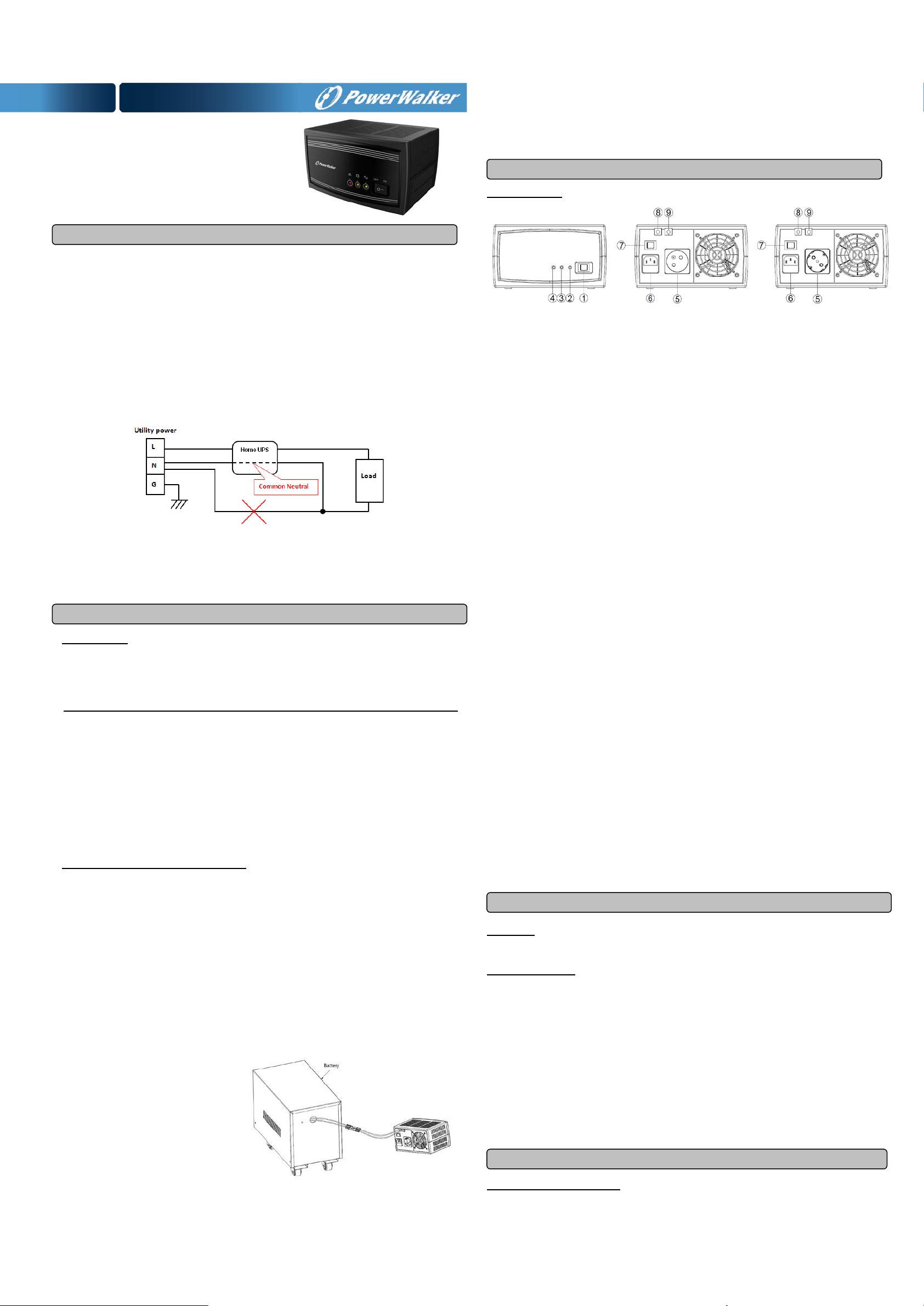
DO NOT connect neutral of the power distribution box on the wall to the output neutral of Inverter.
Otherwise the reversed polarity will damage the Inverter and the connected equipment.
This Inverter ca n be ch ar ge d ev en w hen Inverter is not turn ed o n.
5. Connect the Load
Connect th e eq uipment to the Inverter outlet. Please make s ur e t h at the total loads of you r
equipm ents are less th an th e m axi mu m total power l oad of the Inverter.
BASIC OPERATION
DESCRIPTION
1. Power Switch
Press the power switch to turn the Inverter ON or OFF.
2. AC Mode LED
The green LE D w il l light when utilit y p ow er is normal.
3. Battery Mode LED
The yellow LED wi ll li ght wh en pow er mains ar e ab n or m al and the unit will work in battery mode.
4. Fault LED
The red LE D w ill light when fault or over l oad occurs.
5. AC outlet**
The unit provides one outlet for connected equipment to insure temporary uninterrupted operation
during a power failure and against surges and spikes.
CAUTION! Ri sk of elect r ic shock, do not remove cover. No user serviceable parts inside.
The battery can energize hazardous live parts inside even when the AC input power is disconnected.
T o avoid electrical shock, turn off the Inverter and unplug it from the AC power source before servicing
the battery. Servicing th e battery c an onl y b e performed b y tr ai n ed personn el .
INST A LL ING YOU R Inverter SYSTEM
UNPACKING
Inspect the unit upon receipt. The box should contain the following:
Inverter1; User Manual1; Power cord1
HOW TO DETERMINE THE POWER REQUIREMENTS OF YOUR EQUIPMENT
1. Insure that the equipment plugged into the AC outlet does not exceed the Inverter unit’s rated
capacity (refer to TECHNICAL SPECIFICATIONS ). If rated unit capacities are exc e ed ed, an
overload condition may occur and cause the Inverter unit to shut down or the circuit fuse burn down.
2. If the pow er requirements of you r equip m ent are listed in uni ts ot h er t h an Volt -Amps (VA), convert
Watts (W) or Amps (A) into VA by doing the calculations below. Note: The below equation only
calculates the maximum amount of VA that the equipment can use, not what is typically used by the
equipm en t at any one tim e. Users sh oul d exp ec t usage r equ irements to be appr o xi m at ely 60 % of
below valu e.
HARDWARE INSTA LLATION GUIDE
Before installation, please read and understand the following instructions:
1. Placement
The Inverter must be ins t all ed in a protect ed en vironment away fr om h eat - emitting appl i ances
such as a radiator or heat register. Do not install th is produc t w h ere excess ive moisture is pres ent.
2. Ventilation
The location should provide adequate air flow around the Inverter with 10 CM minimum clearance
on all sid es f or pr op er ven ti l at i on.
3. Connect the Battery
Connect t h e ext ernal batt ery pack with the DC cables from the back of the Inverter. Follow battery
polarity guide located near battery cables as below.
“+” Red cabl e for batt ery p osi t i ve p ol ar it y;
“-” Black cable for battery negative polarity.
4. Connect to AC and Charge the Battery
Connect the Inverter to a wall outl et. Avoid using ext ensi on c ords and adapter plu gs. Char gin g t h e
battery for at least 8 hours is recommended to insure that the battery is fully charged. To recharge
the battery, simply leave the unit plugged into a wall out l et. To maintain optim al b attery ch ar g e,
leave the Inverter p lugged int o an AC outlet at all times.
**Note: 2 outlet types available, including Schuko and FR, type.
6. AC Inlet
Connect to utility power through the input power cord.
7. Input Voltage Range Selector
Input voltage range is defined in specification section. Output voltage is the same as input voltage
in AC mode.
A. Select “Narrow” setting for general electrical appliance such as TUBE LIGHT, ENERGY
SAVING LAMP, TV, JUICER & MIXER etc. It is not suitable for high-power m otor or induc ti ve
load, such as the fridge of 1KW, the motor of 800W, AIR COOLER(h avi ng ris k of reb ooting)
and s o on. In this m od e, the Inverter op eratin g volt ag e in AC mode i s withi n 190~ 260V ac wit h
the sam e outp ut voltag e. The line sensitivity is higher.
B. Select “Wide” setting t o save energ y. In this mode the oper ating range of voltage for th e
Inverter is 100-290V ac. Ther efore the output volt age will be the sam e as the M AINS inpu t
voltag e. The Inverter unit in this mode has a lower s ensiti vity with a longer tr ansfer ti me for
switching from AC mode to battery mode in the event of power failure. You can safely connect
and use home appliances which are not sensitive to transfer time limitations such as florescent
tubes, bu lbs , T V etc .
8. DC Input Cable (Red)
Connec t to battery positive polarity.
9. DC Input Cable (Black)
Connec t to battery negative polarity.
Functional Test
AC Mode
The Inverter d el i ver s p ow er to t h e load d er i ved fr om th e utility an d m aint ains prop er battery c harge.
On-Battery Mode
The Inverter operat es on b attery when t h e uti lity voltag e h as f allen outs id e the li m its . Loc al users are
alerted t o this m od e of operati on by visual an d audibl e ind icators . The Inverter provi des power to the
load from the battery and the output volt ag e of th e Inverter are regulated within a narrow range
1. Swit ch On
Press the power switch then the status LED will light up.
2. Switch Off
Press again the power switch, the status LED will go off.
3. Cold Start / Start on Battery:
This Inverter can be turned on even wh en AC is not pr es ent .
Press the power switch then the status LED will light up.
ROUTINE MAINTENANCE AND STORAGE
ROUTINE MAINTENANCE
1. Use dry soft clothes to clean the panel an d pl astic parts . D o not use an y det ergent that c ontains
alcoholic ingredient.
Page 2
charged)
seconds
voltage)
seconds
voltage)
seconds
seconds
Fault(Temperature
fail)
Fault(Fan fail)
seconds
1. Battery Weak
1. Re-charge battery
2. Battery defective
2. Battery replacement.
fuse
Overload
Remove some non-critical load.
Model
PowerWalker Inverter 650 SW
Cap acity (VA)
650
Cap acity (Watts)
325
Input
Range
Narrow mode: 190VAC-260VAC
Frequency Range
50/60Hz
Output
Voltage
Frequency
Protection
Physical
Receptacles
(HxWxD) (mm)
Weight (Kg.)
4.0
Battery
Lead Acid Battery
12VDC
Warning Diagnosti cs
Indicators
AC Mode, Power On, Battery mode, Fault
Audible Ala rms
Low Battery, Overload, Fault
Environmental
Temperature
Humidity
Management
Auto-Charger
Yes
Auto-Restart
Yes
2. Unplug the Inverter from power inlet if the Inverter will n ot operate for long period of tim e.
STORAGE
1. First turn off your Inverter and disconnect its power cord from the wall outlet. Disconnect all cables
connected the Inverter t o av oi d battery dr ain.
2. The Inverter should be stored in a cool dry location.
3. Make sure the battery is fully charged before the Inverter is stored.
4. For extended storage in moderate climates, the battery should be charged for 12 hours every 3
months by plugging the power cord into the wall receptacle and turning on the main switch. Repeat
it every 2 mon ths in high tem p erature loc at i ons .
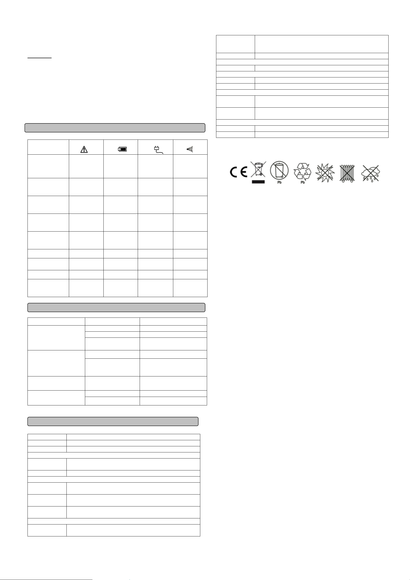
DEFINITIONS FOR INDICATORS
Condition Fault
Normal Mode/ Off
charge mode
(Battery is fully
Off Off On Off
Batter y M od e
AC Mode
Alarm
Maximum
Dimensions
Operating
Operating Relative
115x205x146
0°C to 40°C
0 to 95% NON-CONDENSING
Normal Mode
(Battery is charging)
Batter y M od e
(above l ow b att ery
Batter y M od e
(under low battery
Off charge mode
(Auto bypass)
Fault On Off Off
Overload Normally On but
Off Off Normally On but
blink every 5
Off Normally On but
blink ev er y 30
Off Normally On but
blink ev er y 2
Off Off Normally On but
blink every 5
On Off Off
On
blink ev er y 2
Off Off
Off Off Beeps ever y 0.5
Off Beeps ever y 30
Off Beeps ever y 2
TROUBLE SHOOTING
Problem Possible Causes Remedy
Off
seconds
seconds
Off
On
On
On
seconds
No LED display
Mains n orm al bu t not works in
AC mode
Alarm buzzer beeps
continuously
Backup time is shortened
If any abnormal sit u ati ons occ u r th at are n ot list ed ab ov e, please contact service personnel.
3. Power switch is no t
pressed
1. AC Input missing 1. Check AC input connection.
2. Input Fuse is blown
Overload
Battery voltage is too low. Charge battery for 8 hours or more.
3. Press and hold power switch.
2. Unplug the power cord of the
Inverter then replace the blown
Verify that the load matches the
capability s pecified in the spec s .
TECHNICAL SPECIFICATIONS
Input Voltag e
Wide mod e: 10 0V AC -280VAC
On Battery Output
On Battery Output
Overload
Total # of Inverter
Sine Wave at 230 V ac +/ -10%
50/60Hz
On Utility: fuse On Battery: Internal Current Limiting
(1) Type E or Type F
Page 3

Seria Inverter S W
Instrukcja Obsługi
WAŻNE INSTRUKCJE BEZPIECZEŃSTWA
(ZACHOWAJ TĄ INSTRUKCJĘ)
Ta instrukcja zawiera ważne wskazówki dotyczące bezpieczeństwa. Proszę przeczytać i dokładnie
przestrzegać wszystkich uwag podczas instalacji i użytkowania urządzenia. Przeczytaj tą instruckję
przed odpakowaniem urządzenia.
Podłączając urządzenie do kontaktu zapewnij dobry dostęp. Aby zredukować ryzyko uszkodzeń używaj
tylko baterii dobrej jakości. Upewnij się, że otwory wentylacyjne nie są zakryte. Moduł bateryjny
powinien mieć dobra wentylację, a obudowa nie powinna doprowadzać do akumulacji gazów w jego
górnej części.
Aby uniknąć ryzyka pożaru lub porażenia prądem, należy urządzenie zainstalować w pomieszczeniu z
kontrolowaną wilgotnością i temperaturą wewnątrz budynku. Aby uniknąć ryzyka przegrzenia
urządzenia, nie należy przykrywać otworów wentylacyjnych, użytkować urządzenia w pełnym słońcu ani
przy urządzeniach emitujących ciepło (jak np. grzejniki)
Nie podłączaj przewodu neutralnego z wejścia do wyjścia inwertera (tzw. Neutral bypass). Taka
czynności doprowadzi do uszkodzenia urządzenia.
maksymalnego dopuszczalnego obciążenia.
PODSTAWOWE OPERACJE
OPIS
1. Przycisk on/off
Naciśnij przycisk aby wyłączyć/włączyc inwerter.
2. LED trybu AC
Zielona LED świeci się gdy parametry pracy wejścia I wyjścia sa normalne.
3. LE trybu baterii
Żółta LED świeci się gdy brak zasilana wejściowe, a inwerter pracuje z zasilania baterii
4. Błąd LED
Czerwona LED świeci sie w przypadku błędu urządzenia lub przeciążenia.
5. Gniazdo wyjścia**
Urządzenie posiada gniazdo do podłączenia odbiorników, które mają być chronione przez inwerter
podczas awarii seici.
UWAGA! Ryzyko porażenia prądem. Nie otwieraj obudowy urządzenia.
Bateria może zasilać element y urządzenia nawet gdy napięcie sieci jest odłączone.
powinna być wykonywana przez osobę do tego przeszkoloną.
Wymian a baterii
INSTALACJA INWERTERA
ROZPAKOWYWANIE
Sprawdź opakowanie przy zakupie. W środku powinny się znajdować:
Inwerter1; Instrukcja1; Kabel zasilający1
WYZNACZ CAŁKOWITE OBCIĄŻENIE
1. Upewnij się, że całkowite obciążenie podłączone do Inwertera (watt) nie przekracza dopuszczalnego
obciążenia (zobacz SPECYFIKACJA TECHNICZNA). W przypadku przekroczenia dopuszczalnej
mocy Inwerter wyłączy się lub zadziała bezpiecznik.
2. Jeśli całkowita moc urządzeń podłączonych do UPSa nie jest wyrażona w Voltoamperach (VA),
przelicz moc w Watach dzieląc przez 0.6 (współczynnik mocy inwertera)..
PODŁĄCZENIE URZĄDZENIA
Przeczytaj I zastosuj się do poniższych uwag przez przystąpieniem do instalacji:
1. Umiejscowienie
Inwerter musi być umiejscowiony w bezpiecznej odległości od urządzeń grzewczych. Środowisko
pracy musi miec kontrolowaną temperature I wilgotność.
2. Wentylacja
Zapewnij minimum 10cm przestrzeni do okoła urządzenia dla odpowiedniego przepływu powietrza.
3. Podłącz Baterię
Podłącz zewnętrznę baterię używając
kabla prądu stałego z tyłu inwertera.
Upewnij się, że polaryzacja jest właściwa.
“+” Czerwony kabel oznacza pozytywną
polaryzację
“-“ Czarny kabel oznacza negatywna
polaryzację
4. Podłącz do zasilania I naładuj baterię
Podłącz inwerter to gniazda zasilającego. Unikaj używania przedłużaczy i adapterów. Ładuj baterię
minimum 8h aby zapewnić jej pełną wydajność. Bateria będzie ładowana, jeśli urządzenie jest
podłączone do sieci. Rekomendujemy pozostawienie urządzenia podłączonego do sieci
permanentnie.
Inwerter ładuje baterie nawet gdy jest wyłączony.
5. Podłącz urządzenie
Podłącz urządzenia do wyjścia inwertera. Upewnij się, że nie spowodują przekroczenia
**Ważne: 2 typy wyjść są dostępne, Typ E (używane w Polsce) oraz F.
6. Gniazdo wejścia
Podłącz inwerter do sieci używając tego gniazda.
7. Przełącznik zakresu napięcia wejściowegor
Zakres napięcia wejściowego j est opisana w specyfikacji technicznej. Napięcie wyjściowe jest
takie same jak napięcie wejściowe w trybie AC.
A. Wybierz “Narrow” (wąski zakres) dla typowych zastosowań domowych. Nie stosuj tego trybu
dla motor ów o wys ok iej mocy ani odbiorni k ów in du kcyjnyc h jak duża lodówka, klimatyzacja itp.
B. Wybierz “Wide” (szeroki zakres) aby oszczędzać baterię. W tym trybie inwerter będzie
przełączał na tryb baterii tylko w przypadku bardzo niskiego napięcia lub jego braku. Napięcie
wyjścia będzie takie same jak napięcie wejścia nawet przy 100 voltach. Takie ustawienie jest
wystarczające dla żarówek bądź urządzeń IT z adapterami, które akceptują napięcie 100-250V.
8. Zacisk baterii (czerwony)
Podłącz dodatni terminal baterii.
9. Zacisk baterii (czarny)
Podłącz ujemny terminal baterii.
Funkcjonalność
Tryb AC
In wer ter dostar cz a m oc odbiornikom korzystając z napięcia sieci I ładuje baterię.
Tryb Baterii
Inwerter zasila odbiorniki korzystając z energii zgromadzonej w baterii gdy napięcie wejściowe jest poza
zakresem. Inwerter powiadomi o tym trybie przez sygnał dźwiękowy i świetlny.
1. Włącz
Naciśnij przycisk on/off a dioda zapali się.
2. Wyłącz
Naciśnij przycisk on/off a diode zgaśnie.
3. Cold Start / Włączenie do trybu baterii bez napięca sieci:
Inwerter może zostać włączony bez napięcia sieci korzystając z energii baterii. Naciśnij przycisk
on/off a diode zapali się.
UTRZYMANIE I PRZECHOW YWANIE
UTRZYMANIE
1. Używaj suchej szmatk aby wyczyścić przedni panel I części plastikowe. Nie używaj żadnych
detergentów na alkoholu.
2. Odlącz inwerter od zasilania jeśli nie planujesz go używać przed dłuższy czas.
PRZECHOWYWANIE
1. Najpierw wyłącz inwerter, odłącz odbiorniki I zasilanie.
2. Przechowuj urządzenie w suc hym I chłodnym miejscu.
3. Upewnij się, że bateria jest naładowana do pełna przed magazynowaniem.
Page 4

(Naładowana bateria)
Tryb Normalny (Ładuje
baterie)
co 5s.
Pozi om Bat e ri i )
co 30s.
Poziom Baterii)
co 2s.
co 5s.
Błąd (temperature)
Błąd (wiatrak)
co 2s.
1. Słaba Bateria
1. Naładuj Baterię
2. Uszkodzona Bateria
2. W ymień Baterię
bezpiecznik
Przeciążenie
Odłącz część odbiorników
niskie
Model
PowerWalker Inverter 650 SW
Moc (VA)
650
Moc (Watt)
325
Wejście
Wąski Zakres: 19 0V AC-260VAC
Częstotliwość
50/60Hz
Wyjście
baterii
Częstotliwość
50/60Hz
przeciążeniem
Dane fizyczne
Gniazda
(1) Typ E lub Typ F
(WxSxG) (mm)
Waga (Kg.)
4.0
Bateria
Bateria
12VDC kwas ołowiowy
Diagnostyka
LED
Tryb AC, Status Włączony, Tryb Baterii, Błąd
Alarm
Słaba Bateria, Przeciążenie, Błąd
Środowisko
Temper atu ra Pracy
0°C do 40°C
Wilgotność
0 to 95% bez skraplania
Zarządzanie
Auto-Ładowarka
Tak
Auto-Restart
Tak
4. W przypadku długiego składowania urządzenia w umiarkowanym klimacie, bateria powinna być
doładowana przez 12 godzin co 3 miesiące (poprzed podłączenie jej do inwertera). W przypadku
bardziej surowego klimatu doładuj baterię co 2 miesjące.
OPIS SYGNA LIZA CJ I A UDIOW IZUA LN EJ
Warunek Błąd
Tryb Normalny
Wył.
Tryb Baterii
Wył.
Tryb AC
Wł.
Alarm
Wył.
Wył.
Tryb Baterii (Wysoki
Tryb Baterii (Niski
Ładowanie Baterii
Błąd Wł.
Przeciążenie Włączony, mruga
Wył.
Wył.
Wył.
Wł.
Wł.
ROZWIĄZYWANIE PROBLEMÓW
Problem Możliwy Powód Rozwiązanie
Diody się nie święcą
Napięcie wejściowe normalne,
ale inwerter nie działa
3. Przycisk nie jest
włączony
1. Źle podłączona wtyczka 1. Sprawdź wtyczkę
Przepalony Bezpie cznik
Wył.
Włączony, mruga
Włączony, mruga
Wył.
Wył.
Wył.
Wył.
Wył.
Włączony, mruga
Wył.
Wył.
Włączony, mruga
Wył.
Wył.
Wył.
Wył.
Naciśnij przycisk
2. Odłącz urządzenie I wymieć
Wył.
Dźwięk co 30s.
Dźwięk co 2s.
Wył.
Wł.
Wł.
Wł.
Dźwięk co 0.5s.
Ciągły dźwięk alarmu Przeciążenie Odłącz nadmiarowe odbiorniki
Zbyt krótki czas podtrzymania
na baterii
W przypadku wyżej nieopisanych sytuacji skontaktuj się z serwisem.
Napięcie baterii jest zbyt
Naładuj baterię do pełna
SPECYFIKACJA TECHNICZNA
Zakres Napięcia Szeroki Z akr es : 100VAC-280VAC
Napięcie w trybie
Zabezpieczenie
przed
Sinusoidalne 230Vac +/-10%
Przy napięciu sieci: bezpiecznik
W trybie baterii: Wewnętrzy stycznik
Wymiarys
115x205x146
 Loading...