

Page 1
EN
U
ser manual
POWERWALKER
INVERTER 3000 PSW
EN, RU
Page 2

EN
Page 3

EN
CONTENTS
ABOUT THIS MANUAL ...................................................................................................................................... 1
Purpose ............................................................................................................................................................ 1
Scope ............................................................................................................................................................... 1
IMPORTANT SAFETY INSTRUCTIONS ............................................................................................................ 1
General Precautions ........................................................................................................................................ 1
Personal Precautions ....................................................................................................................................... 2
INSTALLATION ................................................................................................................................................... 3
Unpacking and Inspection................................................................................................................................ 3
Basic Configuration .......................................................................................................................................... 3
Batteries ........................................................................................................................................................... 5
Battery Cable Size ........................................................................................................................................... 5
DC Disconnect and Over-Current Protection .................................................................................................. 5
Battery Cable Connection ................................................................................................................................ 6
AC Cable Size .................................................................................................................................................. 6
AC Connections ............................................................................................................................................... 7
OPERATION ........................................................................................................................................................ 8
Front Panel and Configuration Switch ............................................................................................................. 8
Indicator & Alarm .............................................................................................................................................. 9
Operating Indicators ....................................................................................................................................... 10
Setting Indicators ........................................................................................................................................... 11
SPECIFICATIONS ............................................................................................................................................. 12
Table 5 Line Mode Specifications .................................................................................................................. 12
Table 6 Invert Mode Specifications ................................................................................................................ 13
Table 7 Charge Mode Specifications ............................................................................................................. 14
Table 8 Approximate Back-up Times ............................................................................................................. 15
Table 9 General Specifications ...................................................................................................................... 15
Table 10 Fault code/ Audible alarm ................................................................................................................ 16
TROUBLE SHOOTING ..................................................................................................................................... 17
Page 4

1
EN
ABOUT THIS MANUAL
Purpose
The purpose of this manual is to provide explanations and procedures for installing, operating and
troubleshooting for the unit. This manual should be read carefully before installations and operations.
Please retain this manual for future reference.
Scope
This document defines the functional requirements of the unit, intended for worldwide use in electronic
processing equipment. All manuals are applicable under all operating conditions when installed in the End
Use system, unless otherwise stated.
IMPORTANT SAFETY INSTRUCTIONS
WARNING: This chapter contains important safety and operating instructions. Read and keep
this User Guide for future reference.
General Precautions
1. Before using the unit, read all instructions and cautionary markings on:
(1) The unit (2) the batteries (3) all appropriate sections of this manual.
2. CAUTION --To reduce risk of injury, charge only deep-cycle lead acid type rechargeable batteries.
Other types of batteries may burst, causing personal injury and damage.
3. Do not expose the unit to rain, snow or liquids of any type. The unit is designed for indoor use only.
Protect the unit from splashing if used in vehicle applications.
4. Do not disassemble the unit. Take it to a qualified service center when service or repair is required.
Incorrect re-assembly may result in a risk of electric shock or fire.
5. To reduce risk of electric shock, disconnect all wiring before attempting any maintenance or cleaning.
Turning off the unit will not reduce this risk.
6. CAUTION --Battery are not already installed by the supplier only a qualified professional (e.g. service
person) may install the Inverter.
7. WARNING: WORKING IN VICINITY OF A LEAD ACID BATTERY IS DANGEROUS.
BATTERIES GENERATE EXPLOSIVE GASES DURING NORMAL OPERATION. Provide ventilation
to outdoors from the battery compartment. The battery enclosure should be designed to prevent
accumulation and concentration of hydrogen gas in “pockets” at the top of the compartment. Vent the
battery compartment from the highest point. A sloped lid can also be used to direct the flow to the vent
opening location.
8. NEVER charge a frozen battery.
9. No terminals or lugs are required for hook-up of the AC wiring. AC wiring must be no less than 12 AWG
gauge copper wire and rated for 75oC or higher. Battery cables must be rated for 75oC or higher and
should be no less than table 1. Crimped and sealed copper ring terminal lugs with a 5/16 hole should
be used to connect the battery cables to the DC terminals of the unit. Soldered cable lugs are also
acceptable.
10. Be extra cautious when working with metal tools on, or around batteries. The potential exists to drop a
Page 5

2
EN
tool and short-circuit the batteries or other electrical parts resulting in sparks that could cause an
explosion.
11. No AC or DC disconnects are provided as an integral part of this unit. Both AC and DC disconnects
must be provided as part of the system installation. See INSTALLATION section of this manual.
12. Fuses (F40AL, 32VDC*6) are provided as the over current protection of the battery supply.
13. GROUNDING INSTRUCTIONS -This battery charger should be connected to a grounded permanent
wiring system. For most installations, the Ground Lug should be bonded to the grounding system at one
(and only one point) in the system. All installations should comply with all national and local codes and
ordinances.
14. AVOID AC output short-circuit; avoid DC input short-circuit and do not connect the mains while DC
input short-circuit
15. Warning: The maintenance information is only to service persons
Personal Precautions
1. Someone should be within range of your voice to come to your aid when you work near batteries.
2. Have plenty of fresh water and soap nearby in case battery acid contacts skin, clothing, or eyes.
3. Wear complete eye protection and clothing protection. Avoid touching eyes while working near
batteries. Wash your hands when done.
4. If battery acid contacts skin or clothing, wash immediately with soap and water. If acid enters eyes,
immediately flood eyes with running cool water for at least 15 minutes and get medical attention
immediately.
5. Baking soda neutralizes lead acid battery electrolyte. Keep a supply on hand in the area of the
batteries.
6. NEVER smoke or allow a spark or flame in vicinity of a battery or generator.
7. Be extra cautious when working with metal tools on, and around batteries. Potential exists to
short-circuit the batteries or other electrical parts which may result in a spark which could cause an
explosion.
8. Remove personal metal items such as rings, bracelets, necklaces, and watches when working with
battery. Battery can produce short-circuit current high enough to weld a ring, or the like, to metal
causing severe burns.
9. If a remote or automatic generator start system is used, disable the automatic starting circuit and/or
disconnect the generator from its starting battery while servicing to prevent accidental starting during
servicing.
Page 6
3
EN
INSTALLATION
Unpacking and Inspection
Carefully unpack the inverter/charger from its shipping carton.
Verify all of items list below are present. Please call customer service if any items are missing.
The unit
1 user’s manual
Basic Configuration
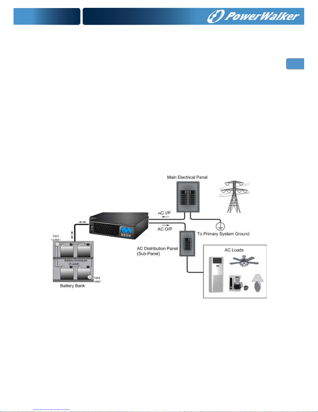
The following illustrations show basic applications for PowerWalker Inverter 3000 PSW.
They include the following configurations:
Utility Backup. see figure 1
Renewable Energy Source And a Generator, see figure 2
Consult with your system design for other possible configurations depending on site or code
requirements.
Figure 1 Utility Backup
PowerWalker Inverter 3000 PSW
Page 7
4
EN
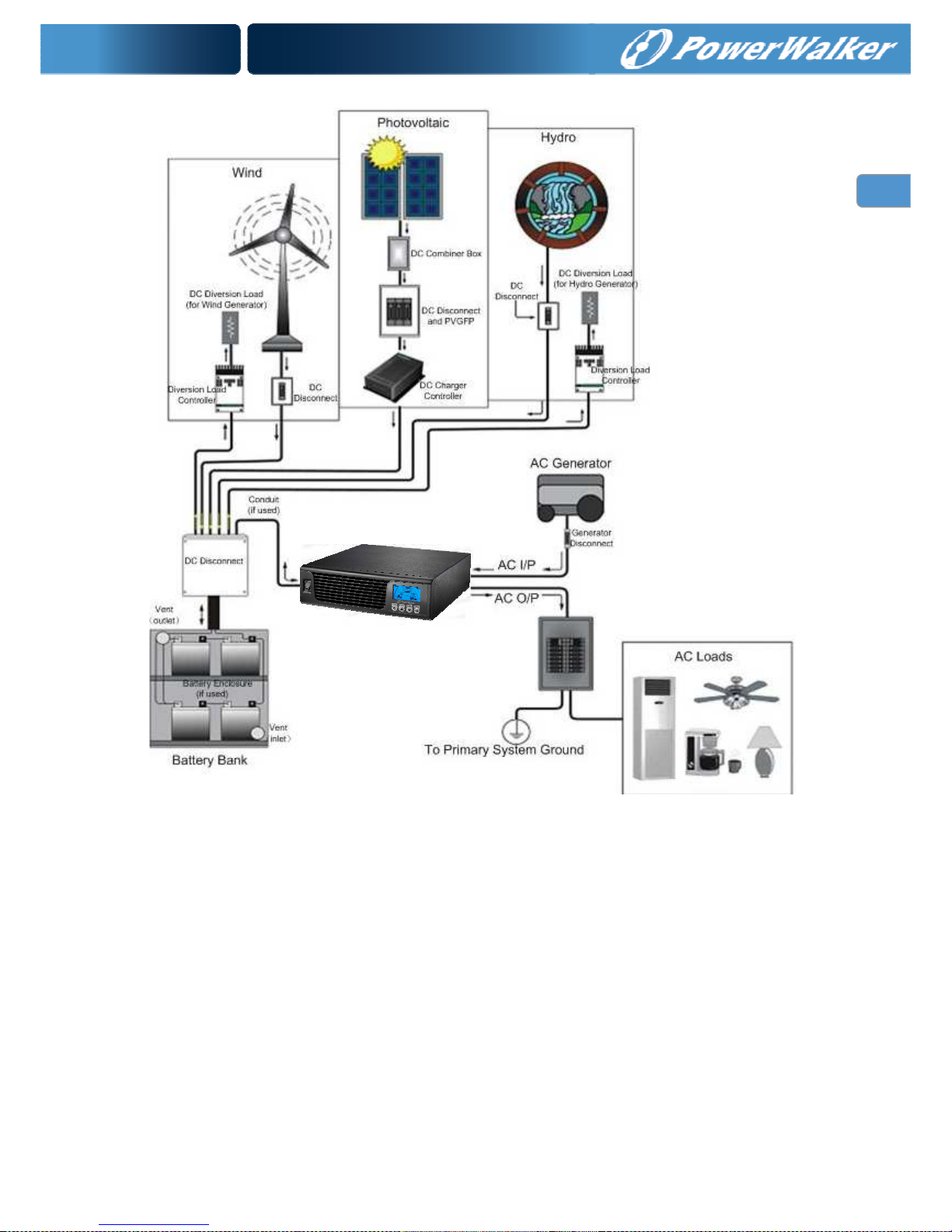
Figure 2 Renewable Energy Source
PowerWalker Inverter 3000 PSW can feeds almost all kinds of appliances from home to office
environment, including motor characteristic appliances like tube light, fan, refrigerator and Air conditioner.
Note: Appliances like Air conditioner needs at least 3 minutes to restart in case of a power shortage
occurs in a way that the power turns off then back on again rapidly (time is required to balance the
refrigerant gas in inside circuit); so in order to protect your Air conditioner, please consult the Air
conditioner manufacturer whether they have already provided time delay function before installing.
Otherwise, Inverter will trig overload fault and shut off its output to protect your appliance but
sometimes it is not enough and your Air conditioner can be damaged internally beyond repair.
PowerWalker Inverter 3000 PSW
Page 8
5
EN
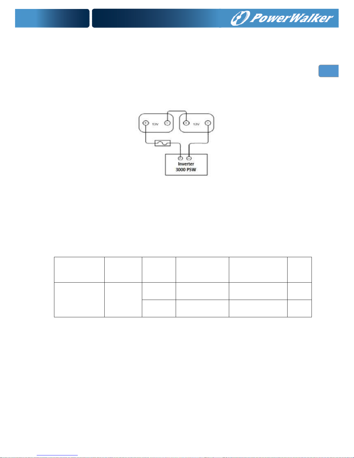
Batteries
The unit support 24volt battery bank. Please refer to figure 3 to wiring battery correctly. Before
proceeding, ensure you have appropriate size batteries for this inverter. The unit can use flooded
lead-acid, or sealed GEL/AGM lead-acid batteries so ensure that your batteries are in one of these
categories.
The battery must be wired to match the units DC input voltage specifications. Suggest battery capacity
not smaller than 100AH.
Figure 3 PowerWalker Inverter 3000 PSW batteries string wiring
Battery Cable Size
Below table 1 you can find information for recommended battery cable and terminal.
Table 1 Recommended battery cable and terminal size
Model
Number
Typical
Amperage
BATTARY
CAPACITY
1~3 m one-way CABLE TERMINAL Torque
value
PowerWalker
Inverter 3000PSW
130A
100 AH 4 AWG
or 2*8AWG
KST:RNBS22-6
(RING TYPE)
5~8
Nm
200 AH 2* 6 AWG KST:RNBS38-6
(RING TYPE)
5~8
Nm
DC Disconnect and Over-Current Protection
For safety and to comply with regulations, battery over-current protection and disconnect devices are
required. Fuses and disconnects must be sized to protect the DC cable size used, and must be rated for
DC operation. Do not use devices rated only for AC service – they will not function properly.
Note that some installation requirements may not require a disconnect device, although over-current
protection is still required.
Page 9
6
EN
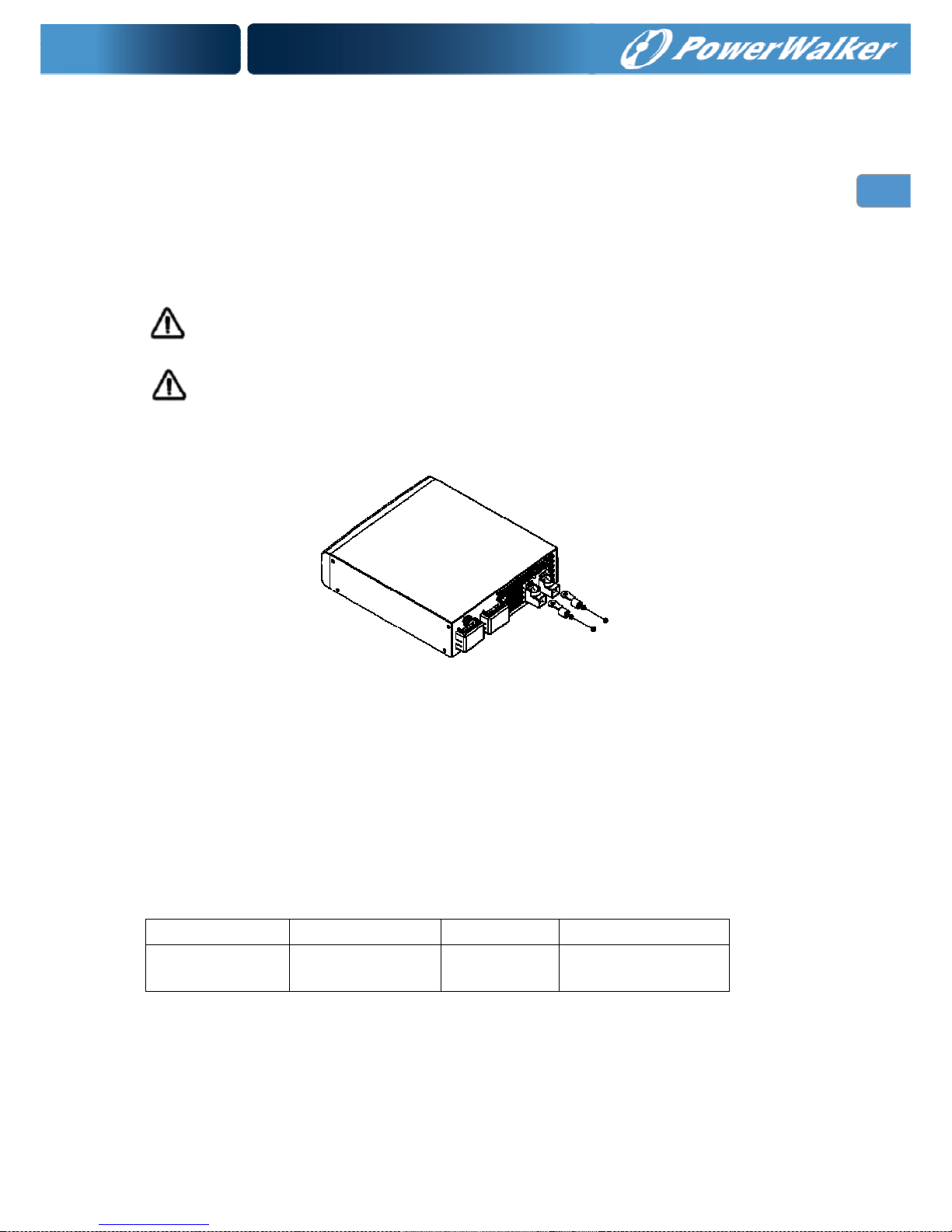
Battery Cable Connection
Observe Battery Polarity! Place the ring terminal of DC cable over the bolt and directly against the unit’s
battery terminal. Tighten the M6 screw with 5-8 Nm. Do not place anything between the flat part of the
Backup System terminal and the battery cable ring terminal or overheating may occur.
DO NOT APPLY ANY TYPE OF ANTI-OXIDANT PASTE TO TERMINALS UNTIL AFTER THE
BATTERY CABLE WIRING IS TORQUED!!
Figure 5 illustrates the proper method to connect the battery cables to the unit terminals.
WARNING: Shock Hazard
Installation must be performed with care for the high battery voltage in series.
Caution!! Do NOT place anything between battery cable ring terminals and terminals on the
inverter. The terminal screw is not designed to carry current.
Apply Anti-oxidant paste to terminals AFTER terminals have been screwed.
Verify that cable lugs are flush with the battery terminals. Tighten battery cables to terminals (5-8 Nm).
Figure 4 Battery Cable Connect to unit
AC Cable Size
Before wiring the input and output of inverter, refer to table 2 for minimum recommended cable size and
torque value
Table 2 Recommended cable size and torque value for AC wire
Model Number AC Input AC Output Torque value
PowerWalker
Inverter 3000 PSW
12AWG 12 AWG 1.2~1.8 Nm
Page 10
7
EN
AC Connections
Installation should be done by a qualified electrician. Consult local code for the proper wire sizes,
connectors and conduit requirements.
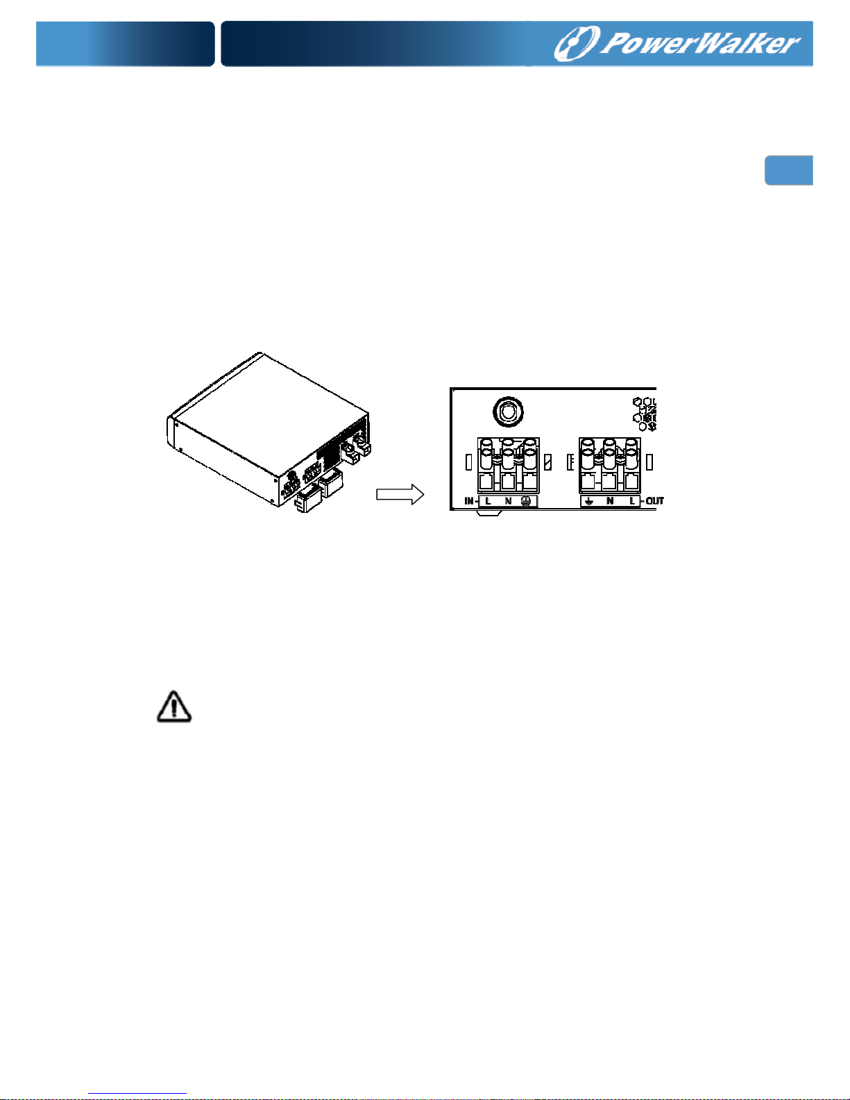
On the left of rear chassis is the AC hardwire cover. Two three-station terminal block is provided to make
the AC connections. The terminal block is used to hardwire the AC input, AC output, and ground. The
National Electrical Code requires that an external disconnect switch be used in the AC input wiring circuit.
The AC breakers in a sub panel will meet this requirement.
Step 1: Disconnect the unit from the battery by removing the battery cables from the battery. Turning off
the unit does not constitute disconnecting from the battery.
Figure 5 AC Cable Connect to unit
Step 2: Following the wiring guide located in the AC input wiring compartment as figure 5, connect the
GND (green/yellow), Line (brown), and neutral (blue) wires from the AC input (utility, generator,
etc) to the terminal block.
Caution!! Be sure that AC source is disconnected before attempting to hardwire it to the unit.
Step 3: Connect the AC Line output wiring to the terminal marked AC Line (output), following the wiring
guide inside the compartment. Torque the wires into the terminal block.
Step 4: Lock the AC covers.
Page 11
8
EN
OPERATION
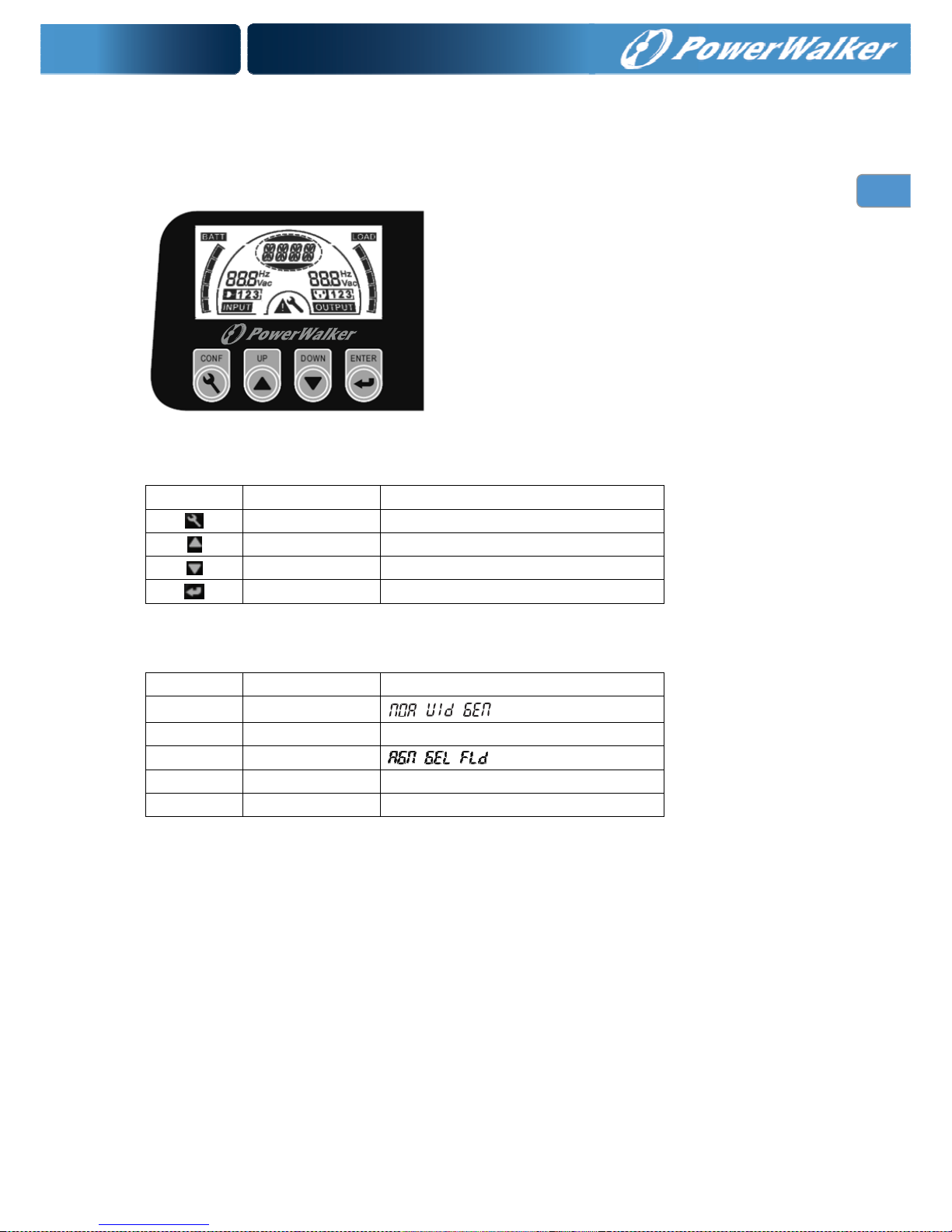
Front Panel and Configuration Switch
Table 3 configuration button function
Switch Function Description
config Enter config mode, and turn page
up Move up to pre-select
down Move down to pre-select
enter Enter to confirm
Table 4 configuration pages option
Page Description Selectable option
1 Input range
2 Output range 230V
3 Battery type
4 Charger current
20A/10A
5 Saver mode ON/OFF
Note: There are 5 configuration pages totally, change only active by enter
button pressed within current page.
Page 12
9
EN
Indicator & Alarm
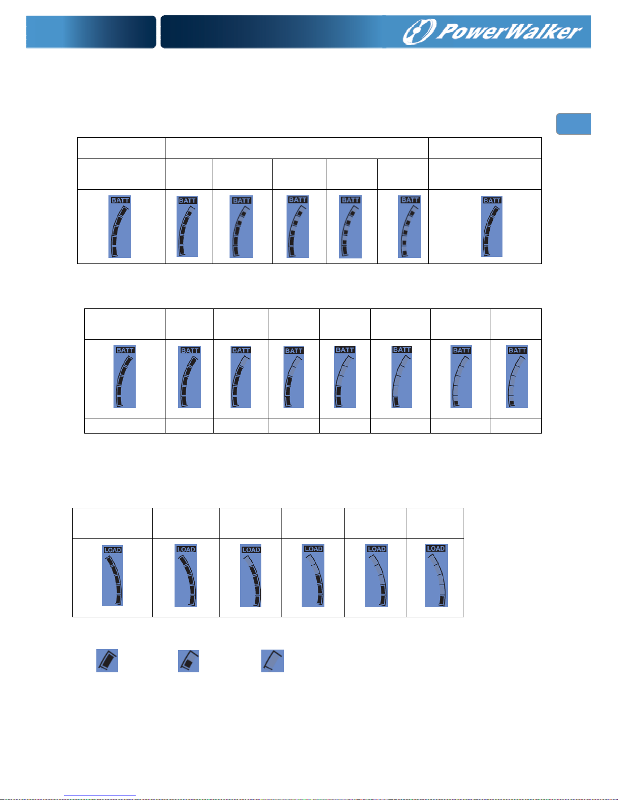
Charger mode battery indicator
Battery capacity segment will lighting to comply with battery voltage
Status CC/CV Floating
Battery
voltage(+/-0.6V)
>26V 25V~26V 24V~25V 21V~24V <21V
Any battery voltage
Inverter mode battery indicator:
Battery
voltage(+/-0.6V)
>26V 25V~26V 24V~25V 23V~24V 21.6V~23V 20V~21.6V <20V
ALARM -- -- -- -- -- 1beep/2s continue
Load indicator:
The load indicate the load percentage comply with load VA or W (show the bigger value), the overload label
will flash when overload.
Load (±4%) >85% 65%~85% 45%~65% 25%~45% 0%~25%
Note:
Solid on; On to off; Off.
Page 13

10
EN
Operating Indicators
Standby Mode: Inverter Mode:
Voltage and Frequency exchanged every 5 seconds Voltage and Frequency exchanged every 5 seconds
Line Mode: Warning Mode:
Voltage and Frequency exchanged every 5 seconds Red back light flash every 1 second
Fault Mode:
Red back light Keep on
Page 14

11
EN
Setting Indicators
Page 15

12
EN
SPECIFICATIONS
Table 5 Line Mode Specifications
MODEL PowerWalker Inverter 3000 PSW
Input Voltage Waveform
Sinusoidal (utility or generator)
Nominal Input Voltage
230Vac
Low Line Disconnect
170Vac±4%(NOR)
90Vac±4%(GEN/WID)
Low Line Re-connect
180Vac±4% (NOR)
100Vac±4% (GEN/WID)
Note:
1.NOR setting can be used for general electrical appliance
2. WID setting can be used only for some special load, such as lamp, fan.
High Line Disconnect
280Vac±4%
High Line Re-connect
270Vac±4%
Max AC Input Voltage
300Vac rms
Nominal Input Frequency
50Hz / 60Hz (Auto detection)
Low Line Frequency Disconnect
40±1Hz
Low Line Frequency
Re-connect
42±1Hz
High Line Frequency Disconnect
65±1Hz
High Line Frequency Re-connect
63±1Hz
Output Voltage Waveform
As same as Input Waveform
Output Short Circuit Protection
30A Circuit Breaker
Efficiency (Line Mode)
>95% ( Rated R load, battery full charged )
Transfer Switch Rating
30A
Transfer Time
10ms (typical) 15ms max(NOR)
20ms (typical) 40ms max(GEN/WID)
Bypass charger enable in off mode
Yes
Power Limitation
Page 16

13
EN
Table 6 Invert Mode Specifications
MODEL PowerWalker Inverter 3000 PSW
Output Voltage Waveform
Pure Sine Wave
Rated Output Power
3000VA
Power Factor
0.8
Nominal Output voltage
230Vac
Minimum Peak Output Voltage at
Rated Power
>200V
Output Frequency(Hz)
50Hz / 60Hz ± 1Hz (follow first connect to grid)
Output Voltage Regulation
±10% Vrms
Nominal Efficiency
>90% (@Normal DC Input; >60% R load)
Over-Load Protection
fault after 5s@≥150% load,<=200% load
fault after 10s@110%~150% load,
Surge rating
6000VA
Capable of starting electric motor
1.5HP
Output Short Circuit Protection
Current limit (Fault after 4 cycles max)
Nominal DC Input Voltage
24V
Min DC start voltage
20V
Low DC Alarm
21.0 ± 0.6Vdc
Low DC Alarm Recovery
21.6 ± 0.6Vdc
Low DC Shut-down
20.0 ± 0.6Vdc
Low DC Shut-down Recovery
22.0 ± 0.6Vdc
High DC Shut-down
30.0 ± 0.6Vdc
High DC Shut-down Recovery
29.0 ± 0.6Vdc
DC component of output
<100mV
Power Limitation
Page 17

14
EN
Table 7 Charge Mode Specifications
Nominal Input Voltage
230Vac
Input Voltage Range
180V - 270Vac(NOR)
100V - 270Vac(GEN/WID)
High Voltage Disconnect
280Vac±4%
High Line Re-connect
270Vac±4%
Low Voltage Disconnect
170Vac(NOR)
90Vac(GEN/WID)
Low Line Re-connect
180Vac±4% (NOR)
100Vac±4% (GEN/WID)
Nominal Output Voltage
Refer to Charge Algorithm/ Battery Type Setting
Nominal Charge Current
10A @Vi/p<170Vac
20A@Vi/p=230Vac
10A @Vi/p>280Vac
Charge current tolerance
±10%
Over Charge Protection
Bat. V ≥30Vdc, Fault, Buzzer alarm
Charge Algorithm
Three stage:
Boost CC (constant current stage) → Boost CV
(constant voltage
stage) → Float (constant voltage stage)
Battery Type Setting(+/-0.3v/bat)
Battery Type
Boost CC/CV Float
Voltage(V) Voltage(V)
24 24
Flooded 29.2 27.0
AGM / Gel 28.2 27.0
Charger current (+/-10%)
Charge(A)
20
Note: NOR – Normal range; GEN-Generator range; WID-Wide range
Page 18

15
EN
Table 8 Approximate Back-up Times
Load(VA)
100Ah 24VDC(min) 200AH 24VDC(min)
300 457.5 972.2
600 208.1 499.5
900 140.6 262.3
1200 103 178.1
1500 77.8 138.3
1800 57.6 113.2
2100 49.5 100.5
2400 41.4 87.9
2700 33.2 75.3
3000 28.4 62.6
Note: Back-up times depend on the quality of the battery, age of battery and type of battery.
Specifications of batteries vary from one manufacturer to another.
Table 9 General Specifications
Safety Standard
EN60950-1:2006+A1: 2010
EN62040-1-1: 2008
EMC Standard
EN62040-2 : 2006 C2
Operating
Temperature Range
0°C to 45°C
Storage temperature
-15°C~ 60°C
Altitude, operational
Elevation: 0 – 1500 Meters
Relative humidity
5% to 95% non-condensing
Audible Noise
60dB max
Cooling
Forced air
Dimension(L*W*H)
330mm*268mm*76mm
Net Weight
4.9KG
DC wiring
Double 6 AWG cable for each polarity
AC input/output
L/N/G:12AWG
Page 19

16
EN
Table 10 Fault code/ Audible alarm
Operate Condition
--
Low DC
Voltage
Alarm
Inverter DC voltage<Low DC Alarm 1beep/2s -- -- --
0
Low DC
Voltage
Protection
Inverter
DC Voltage<Low DC Shutdown
--
Beep
continuous
Auto
Mains is
normal
1
Over
Charge
Protection
Line
DC Voltage>High DC input
Shut-down
Beep
continuous
-- Manual --
1
Over
Voltage
Protection
Standby
DC Voltage>High DC input
Shut-down
--
Beep
continuous
Auto
DC
Voltage<High
DC input
Shut-down
Recovery
Line/
Inverter
110%~150% load
1beep/0.5s,and
continuous 10s
Beep
continuous
Manual --
Line/
Inverter
>150% load
1beep/0.5s,and
continuous 5s
Beep
continuous
Manual --
3
Output
Short
Circuit
Protection
Inverter
1)Output Voltage<20Vrms
2)TX temperature>102
℃
--
Beep
continuous
Manual --
4
Fan Fault
Protection
Line/
Inverter
Fan Locked
Fan Defected
2beep/2s, and
continous 1min
Beep
continuous
Manual --
5
Over
Temp
Protection
Line/
Inverter
HEAT SINK Temp≥100℃
--
Beep
continuous
Auto
HEAT SINK
Temp≤ 55℃
6
Output
Abnormal
Inverter
1)Output Voltage<170Vrms
or Output Voltage>250Vrms
2)TX temperature>102℃
--
Beep
continuous
Manual --
Fault
(O/P=OFF)
Restart
2
Over Load
Protection
Active
Mode
Condition
Warning
(O/P=ON)
Fault
Code
Protect
Function
Page 20

17
EN
TROUBLE SHOOTING
Problem Possible Causes Remedy
No LCD display
1. Battery Weak 1. Re-charge battery
2. Battery defective (can't be
charged)
2. Battery replacement
3. Power switch is not pressed 3. Press and hold power switch
4. Battery polarity reversed, can’t
start up the unit
4. Sent back for repair
Mains normal but
works in inverter
mode
1. AC Input missing 1. Check AC input connection
2. Input protector is effective 2. Reset the input protector
Mains normal but
can’t works in
inverter mode
1. Battery disconnected 1. Connect batteries
2. Low batteries 2. Recharge batteries or change new batteries
Alarm buzzer
beeps
continuously
1. Overload(fault code: F2)
1. Verify that the load matches the capability
specified in the specs
2. Output short circuit(fault code: F3) 2. Check wiring or remove abnormal load
3. Over temp(fault code: F5) 3. Move away barrier in front of airflow inlet
4. Over charger(fault code: F1) 4. Restart the unit
5. Over voltage(fault code: F1)
5. Turn down the DC input voltage below the high
DC input shut-down recovery
6. Fan fault(fault code: F4)
6. Check if something block the fan, if not replace
the fan
7. DC voltage under the low DC
shut-down(fault code: F0)
7. Make sure mains is normal to recharger the
battery if not switch the power off until mains is
normal
8. Output abnormal(fault code: F6) 8. Send back for repair
Back up time is
shortened
1. Overload 1. Remove some non-critical load
2. Battery voltage is too low 2. Charge battery for 8 hours or more
3. Battery bank is too small 3. Increase battery bank capacity
Page 21

RU
Руководство
пользователя
Инвертор POWERWALKER
3000 PSW
RU
Page 22

0
RU
Содержание
Кратко о руководстве ...................................................................................................................................... 1
Цель ................................................................................................................................................................. 1
Сфера действия ............................................................................................................................................. 1
ВАЖНЫЕ ИНСТРУКЦИИ ПО БЕЗОПАСНОСТИ ............................................................................................ 1
Основные предостережения ......................................................................................................................... 1
Личные меры предосторожности .................................................................................................................. 2
УСТАНОВКА ....................................................................................................................................................... 3
Распаковка и осмотр ...................................................................................................................................... 3
Базовая конфигурация .................................................................................................................................. 3
Батареи ........................................................................................................................................................... 5
Размер батарейных кабелей ......................................................................................................................... 5
Отсоединение постоянного тока и защита от скачков тока ........................................................................ 5
Подсоединение батарейного кабеля ............................................................................................................ 6
Размер кабеля переменного тока ................................................................................................................. 6
Подсоединения переменного тока ............................................................................................................... 7
РАБОЧИЕ ОПЕРАЦИИ ...................................................................................................................................... 8
Передняя панель и конфигурации коммутатора ......................................................................................... 8
Индикаторы & Сигналы тревоги.................................................................................................................... 9
Индикаторы операций ................................................................................................................................. 10
Индикация настроек ..................................................................................................................................... 11
ХАРАКТЕРИСТИКИ ......................................................................................................................................... 12
Таблица 5 Характеристики - режим питания от сети .............................................................................. 12
Таблица 6 Характеристики – режим инвертора ......................................................................................... 13
Таблица 7 Характеристики – режим зарядки ............................................................................................. 14
Таблица 8 Примерное время автономной работы .................................................................................... 15
Таблица 9 Общие характеристики .............................................................................................................. 15
Таблица 10 Коды ошибок/ Звуковой сигнал ............................................................................................... 16
УСТРАНЕНИЕ НЕИСПРАВНОСТЕЙ ........................................................................................................... 17
Page 23

1
RU
Кратко о руководстве
Цель
Целью этого руководства является формулировка описаний и формирование процедур по
установке, функционированию и устранению неисправностей устройства. Рекомендуем тщательно
изучить данное руководство, и держать в доступном месте для будущего использования.
Сфера действия
Этот документ определяет функциональные требования к устройству, и предназначен для
использования во всем мире в сфере электронных устройств для обработки информации. Все
руководства применимы при любых условиях эксплуатации при установке их в системах для
конечного использования, если только не сказано иное.
ВАЖНЫЕ ИНСТРУКЦИИ ПО БЕЗОПАСНОСТИ
ВНИМАНИЕ!: Эта глава содержит важные инструкции по эксплуатации и безопасности.
Ознакомьтесь и храните данное руководство для будущего использования.
Основные предостережения
1. Перед использованием устройства прочитайте все инструкции и предупреждающие надписи:
(1) На устройстве (2) На батареях (3) и все соответствующие разделы данного руководства.
2. ВНИМАНИЕ! Для снижения риска повреждений заряжайте только аккумуляторы
свинцово-кислотного типа глубокого цикла. Другие типы батарей могут взрываться и причинять
персональные травмы и повреждения.
3. Не подвергайте устройство действию дождя, снега и других жидкостей любого типа. Устройство
разработано для использования только внутри помещений. Защищайте устройство от брызг,
если оно используется в транспортных средствах.
4. Не разбирайте устройство. При необходимости обслуживания или ремонта предоставьте
устройство в квалифицированный сервисный центр. Неправильный демонтаж может являть
собой риск удара тока или ожога от огня.
5. Чтобы снизить риск удара током, отсоедините все провода перед попыткой любого действия по
обслуживанию или чистке. Просто выключенное устройство не снижает такой риск.
6. ВНИМАНИЕ –Если батарея не установлена поставщиком, только квалифицированный персонал
(например, представитель сервисного центра) может производить запуск Инвертора.
7. ПРЕДУПРЕЖДЕНИЕ: РАБОТА В КОНТАКТЕ СО СВИНЦОВО-КИСЛОТНЫМИ БАТАРЕЯМИ
ОПАСНА. БАТАРЕИ ГЕНЕРИРУЮТ ВЗРЫВООПАСНЫЕ ГАЗЫ ДАЖЕ ПРИ НОРМАЛЬНОМ
ФУНКЦИОНИРОВАНИИ. Обеспечьте вентиляцию батарейного отделения воздухом извне.
Батарейное приложение должно быть разработано без возможности скопления водорода в
«карманах» верхней части отделения. Батарейное отделение должно проветриваться с самой
его высокой точки. Крышка с наклоном может также использоваться для направления потока
обдува к вентиляционным отверстиям.
8. НИКОГДА НЕ заряжайте замороженную батарею.
9. Никакие клеммы или наконечники не требуются монтирования проводки переменного тока.
Проводка переменного тока должна быть сделана из медного провода не менее чем 12 AWG,
которые рассчитаны на 75oC или более. Батарейные кабели должны быть рассчитаны на 75oC
Page 24

2
RU
или более, и должны иметь параметры не менее чем в Таблице 1. Нарезные и герметичные
наконечники медного кольца с отверстием 5-16 предназначены для подсоединения батарейных
кабелей к терминалам выхода постоянного тока устройства. Припаянные кабельные
наконечники также пригодны к использованию.
10. Будьте особенно осторожны, когда работаете металлическим инструментом поблизости батарей.
Существует потенциал, который может через проводящий инструмент спровоцировать короткое
замыкание между батареями или другими электрическими деталями, что создаст искрение, что в
свою очередь может стать причиной взрыва.
11. Прерыватели цепи переменного и постоянного тока не являются частями комплекта поставки
устройства. Эти прерыватели должны быть обеспечены в качестве материалов для монтажа
при установке системы. См. раздел УСТАНОВКА данного руководства.
12. Предохранители (F40AL, 32VDC*6) необходимы как защита питания батарей от всплесков тока.
13. ИНСТРУКЦИИ ПО ЗАЗЕМЛЕНИЮ Зарядное устройство батареи должно подключаться к
системе проводов, которая надежно заземлена. Для большинства инсталляций наконечник
заземления должен быть соединен с системой заземления в одной и только одной точке системы.
Все установки должны соответствовать всем национальным и местным нормам и правилам.
14. ИЗБЕГАЙТЕ короткого замыкания на выходе переменного тока; избегайте короткого замыкания
на входе постоянного тока и не производите подсоединение к сети питания при коротком
замыкании на входе постоянного тока
15. Внимание!: Информация по обслуживанию – только для сервисного персонала
Личные меры предосторожности
1. Кто-то должен присутствовать на расстоянии вашего голоса, чтобы в случае необходимости
прийти к вам на помощь, когда вы работаете с(около) батареями.
2. Имейте рядом достаточно свежей воды и мыло на случай контакта кислоты из батарей с кожей,
одеждой или глазами.
3. Носите защитные средства для глаз и одежды. Избегайте касания к глазам при работе вблизи
батарей. После работы мойте руки.
4. Если кислота из батареи попала на кожу или одежду, промойте это место немедленно с водой и
мылом. Если кислота попала в глаза, немедленно промойте глаза прохладной проточной водой
в течение не менее 15минут и обратитесь за медицинской помощью.
5. Пищевая сода нейтрализует электролит из свинцово-кислотных батарей. Держите ее под рукой
вблизи расположения батарей.
6. НИКОГДА НЕ курите и не позволяйте возникновения искр или пламени в непосредственной
близости от батарей или генератора.
7. Будьте особенно осторожны, когда работаете металлическим инструментом с или поблизости
батарей. Существует потенциал, который может через проводящий инструмент спровоцировать
короткое замыкание между батареями или другими электрическими деталями, что создаст
искрение, что в свою очередь может стать причиной взрыва.
8. Снимите личные вещи из металла: кольца, браслеты, ожерелья, часы при работе с батареями.
Батарея может давать ток короткого замыкания, который является достаточно высоким для
плавки металла кольца, что может повлечь серьезные ожоги.
9. Если используется система удаленного или автоматического запуска от генератора, отключите
цепь автоматического запуска и/или отсоедините генератор от его стартовой батареи, пока
производите сервисное обслуживание для предотвращения случайного запуска во время работ.
Page 25

3
RU
УСТАНОВКА
Распаковка и осмотр
Внимательно распакуйте инвертор/зарядное устройство и выньте его из транспортной коробки.
Убедитесь, что нижеуказанное есть в наличии. Обратитесь в службу поддержки, если какие-либо
элементы отсутствуют.
Устройство
1 руководство пользователя
Базовая конфигурация
Ниже приведен пример базового применения Инвертора PowerWalker 3000 PSW.
Изображены следующие конфигурации:
Автономная работа от устройства – Рис. 1
Пополняющиеся источники энергии и генератор - Рис. 2
Проконсультируйтесь с вашими разработчиками системы для других возможных конфигураций в
зависимости от требований местности или кодировок.
Рис. 1 Автономная работа от устройства
Инвертор PowerWalker 3000 PSW
Page 26

4
RU
Figure 2 Renewable Energy Source
Инвертор PowerWalker 3000 PSW может питать почти все виды приложений в домашней и
офисной среде, в том числе приложения с моторизованными характеристиками, такие как
трубкообразное освещение, вентиляторы, холодильники и кондиционеры.
Примечание: Такие приложения, как кондиционер, требуют как минимум 3 минуты для перезапуска
в случае, если падение сети питания происходит таким образом: питание пропадает в сети,
и возобновляется очень быстро (кондиционеру требуется время для балансировки
газа-хладагента внутри его канала циркуляции). Поэтому для защиты кондиционера воздуха
проконсультируйтесь у его производителя, реализуется ли функция обеспечения временной
отсрочки повторного запуска перед установкой кондиционера. В противном случае, инвертор
воспримет такой сбой как перегрузку, и заблокирует этот выход питания для защиты
Инвертор PowerWalker 3000 PSW
Page 27

5
RU
приложения, но иногда эта мера является недостаточной, и кондиционер получит внутренние
повреждения, не подлежащие ремонту.
Батареи
Устройство поддерживает батарейный комплект 24Вольт. См. Рис. 3 для корректного соединения
батарей. Перед работой убедитесь, что батареи соответствуют данному инвертору. Устройство
может использовать жидкие(доливаемые) свинцово-кислотные аккумуляторы, или герметичные
свинцово-кислотные гелевые или с поглощающим стекловолокном. Поэтому проверьте, относятся
ли аккумуляторы к одной из этих категорий.
Батареи соединяются таким образом, чтобы соответствовать параметру устройства по значению
входного напряжения постоянного тока. Емкость батареи рекомендована не менее 100Ач.
Рис. 3 Подключение батарей гирляндой к Инвертору PowerWalker 3000 PSW
Размер батарейных кабелей
Ниже в Таблице 1 содержатся рекомендации по выбору батарейных кабелей и их наконечников.
Таблица 1 Рекомендованные батарейные кабели и их наконечники
Номер модели
Типичная
амперность
Емкость
батареи
1~3 метра в
одну
сторону
Кабельный
наконечник
Крутящий
момент
Инвертор
PowerWalker
3000PSW
130A
100 Ач
4 AWG
или 2*8AWG
KST:RNBS22-6
(типа кольцо)
5~8 Нм
200 Ач
2* 6 AWG
KST:RNBS38-6
(типа кольцо)
5~8 Нм
Отсоединение постоянного тока и защита от скачков тока
Для соблюдения правил безопасности, батарее требуется защита от скачков, а также возможность
отключения устройств. Предохранители и прерыватели должны быть рассчитаны для защиты
выбранных размеров кабелей постоянного тока, и должны быть рассчитаны на работу с
постоянным током. Не используйте устройства, рассчитанные на работу только с переменным
током – они не будут работать должным образом.
Имейте в виду, что некоторые требования по установке могут не требовать отсоединения
устройства, однако все же требуют наличие защиты от скачков тока.
Page 28

6
RU
Подсоединение батарейного кабеля
Соблюдайте полярность батарей! Расположите кольцо наконечника кабеля постоянного тока над
болтом и прямо напротив клеммы батареи устройства. Затяните винт M6 с 5-8 Нм. Не размещайте
ничего между плоской частью терминала системы резервного копирования и кольцом
наконечника батарейного кабеля во избежание перегрева.
НЕ НАНОСИТЕ АНТИОКСИДАНТНУЮ ПАСТУ НИКАКОГО ТИПА НА ТЕРМИНАЛЫ ДО ТОГО,
ПОКА БАТАРЕЙНЫЙ КАБЕЛЬ ЕЩЕ НЕ ПРИКРУЧЕН !!
Рис 4 показывает правильный способ присоединения батарейного кабеля к терминалам
устройства.
ВНИМАНИЕ: Опасность поражения электрическим током
Установка должна выполняться с осторожностью из-за высокого напряжения батареи и
последовательно.
Предупреждение!! Ничего не располагайте между кольцом наконечника батарейного
кабеля и терминалами инвертора. Винт терминала не предназначен для проводки тока.
Применяйте антиоксидантную пасту к терминалам ПОСЛЕ соединения терминалов кабеля и
инвертора.
Убедитесь, что наконечники кабелей расположены на одном уровне, вровень с батарейными
терминалами. Прикрутите батарейные кабели к терминалам (5-8 Нм).
Рис 4 Батарейный кабель, подсоединенный к устройству
Размер кабеля переменного тока
Перед подключением входа и выхода инвертора ознакомьтесь с указанными в Таблице 2
минимальными рекомендованными размерами кабеля и крутящего момента
Таблица 2 Рекомендованные размеры кабеля и крутящего момента для проводки переменного
тока
Номер модели
Вход переменного
тока
Выход
переменного тока
Крутящий
момент
Инвертор PowerWalker
3000 PSW
12 AWG
12 AWG
1.2~1.8 Нм
Page 29

7
RU
Подсоединения переменного тока
Установка должна выполняться квалифицированным электриком. Уточните местную кодировку и
требования к надлежащему сечению проводов, коннекторам и кабель-каналам.
Слева на заднем шасси расположена крышка клемм разводки кабелей переменного тока. Два
блока клемм, каждый с тремя контактами, предназначен для подключения переменного тока.
Клеммный блок используется для разводки с жестким креплением входного переменного тока,
выходного переменного тока, и заземления. Национальный кодекс безопасности электромонтажа
требует наличие внешнего рычага прерывателя для электрической цепи переменного тока.
Прерыватели переменного тока, размещенные на дополнительной панели, соответствуют этим
требованиям.
Шаг 1: Отсоедините устройство от батареи путем отсоединения батарейного кабеля от батареи.
Просто выключенное устройство не означает отсутствие контакта с батареей.
Рис 5 Кабель переменного тока подсоединен к устройству
Шаг 2: Следуйте обозначениям по разводке, расположенным на блоке подсоединения входа
переменного тока, как показано на Рис 5, подсоедините GND (зеленый/желтый), Line
(коричневый), и нейтраль(N) (синий) провода входного кабеля переменного тока (от сети
здания, генератора, и прочее) к входному блоку клемм.
Внимание!! Убедитесь, что источник переменного тока отсоединен перед попытками
приступить к жесткому подсоединению его к устройству.
Шаг 3: Подсоедините провод Line выходного кабеля переменного тока к клемме на выходном
блоке переменного тока, обозначенной АC Line (output), следуя маркировке проводов
внутри отсека. Прикрепите провода к клеммам блока.
Шаг 4: Закройте крышку панели переменного тока.
Page 30

8
RU
РАБОЧИЕ ОПЕРАЦИИ
Передняя панель и конфигурации коммутатора
Таблица 3 Функции конфигурационных кнопок
кнопка
функция
Описание
config
Ввод конфигурационного режима,
перемотка страниц
up
Движение вверх для выбора
down
Движение вниз для выбора
enter
Ввод как подтверждение
Таблица 4 Значение страниц конфигурирования
Страница
Описание
Опции для выбора
1
Входной диапазон
2
Выходной диапазон
230V 3 Тип батареи
4
Ток зарядки
20A/10A
5
Режим экономии
ON/OFF
Примечание: Всего есть 5 страниц конфигурации, изменение страницы считается внесенным,
только если нажата кнопка enter, когда находимся на текущей странице
Page 31

9
RU
Индикаторы & Сигналы тревоги
Индикатор режима зарядки батареи
Шкала емкости батарей подсвечивается по сегментам в соответствии с напряжением батарей
Статус ЗАРЯДКИ
CONSTANT CURRENT/CONSTANT VOLTAGE(постоянный
ток/постоянное напряжение)
Скользящий режим
Напряжение
батареи(+/-0.6В)
>26В
25В~26В
24В~25В
21В~24В
<21В
Любое напряжение
батареи
Индикатор батареи в режиме инвертора:
Напряжение
батареи
(+/-0.6В)
>26В
25В~26В
24В~25В
23В~24В
21.6В~23В
20В~21.6В
<20В
Сигнал тревоги
--
--
--
--
--
1сигнал/
2секунды
Продолжительный
Индикатор нагрузки:
Нагрузка указывает процент нагрузки в соответствии с ВА или Вт нагрузки (показывает большее
значение), метка перегрузки будет мигать, если перегрузка есть.
Нагрузка (±4%)
>85%
65%~85%
45%~65%
25%~45%
0%~25%
Примечание:
Точно еще есть; Есть но исчезает; Отсутствует полностью.
Page 32

10
RU
Индикаторы операций
Режим ожидания: Режим инвертора:
Значение напряжения и частоты выводятся Значение напряжения и частоты выводятся
по очереди каждые 5 секунд по очереди каждые 5 секунд
Режим от сети: Режим предупреждения:
Значение напряжения и частоты выводятся Красная подсветка мигает каждую секунду
по очереди каждые 5 секунд
“1”: Normal
“3”: Wide
“2”: Generator
“OVLD”: Overload Warning
“FAN”: Fan Abnormal Warning
“BATT”: Battery Low Warning
1 – Нормальный 2 – Генератор 3- - Широкий OVLD - Перегрузка BATT – низкий заряд батарей
FAN – сбой вентилятора
Режим сбоя:
Красная подсветка горит непрерывно
“F 0”: Low DC Voltage
“F 1”: Over Charge
“F 3”: Output Short
“F 4”: Fan Fault
“F 6”: Output Abnormal“F 2”: Over load
“F 5”: Over Temperature
F0 – низкое напряжение постоянного тока F1 – Перезарядка F2 – Перенагрузка F3 – Выходное
питание отсутствует F4 – сбой вентилятора F5 – превышение температуры F6 - выходное
питание недопустимой величины
Page 33

11
RU
Индикация настроек
Настройка входного диапазона
Нормальный режим Режим от генератора Широкий режим
Настройка типа батарей
С абсорбированным электролитом (AGM) Гелевые Доливаемые
Настройка тока зарядки
Высокий ток (20А) Низкий ток(10А)
Настройка режима экономии
Режим экономии выключен Режим экономии включен
Page 34

12
RU
ХАРАКТЕРИСТИКИ
Таблица 5 Характеристики - режим питания от сети
МОДЕЛЬ
Инвертор PowerWalker 3000 PSW
Форма входного напряжения
Синусоида (сеть питания или генератор)
Номинальное входное напряжение
230В
Порог отключения при понижении напряжения сети
170В±4%(NOR)
90В±4%(GEN/WID)
Порог обратного подключения при сниженном
напряжении сети
180В±4% (NOR)
100В±4% (GEN/WID)
Примечание:
1.NOR используется для обычных приложенийe
2. WID используется только для специфической
нагрузки, такой как лампы, вентиляторы.
Порог отключения при повышении напряжения сети
280В±4%
Порог обратного подключения при повышенном
напряжении сети
270В±4%
Максимальное входное напряжение переменного тока
300В rms
Номинальная входная частота
50Гц / 60Гц (Авто определение)
Отключение – низкий предел частоты
40±1Гц
Обратное подключение – низкий предел частоты
42±1Гц
Отключение – высокий предел частоты
65±1Гц
Обратное подключение – высокий предел частоты
63±1Гц
Форма выходного напряжения
Такая же как и входного
Защита от короткого замыкания на выходе
30A прерыватель цепи
Эффективность (режим от сети)
>95% ( Номинальная нагрузка, полный заряд
батареи )
Предел для автоматического перехода
30A
Время перехода
10мс (типичное) 15мс макс(NOR)
20мс (типичное) 40мс макс(GEN/WID)
Панель обходного режима при отключении
Да
Ограничение по мощности
Input Voltage
Output Power
3KVA/2.4KW
1.5KVA/1.2KW
90V 180V
280V
Page 35

13
RU
Таблица 6 Характеристики – режим инвертора
МОДЕЛЬ
Инвертор PowerWalker 3000 PSW
Форма выходного напряжения
Чистая синусоида
Номинальная выходная мощность
3000ВA
Коэффициент мощности
0.8
Номинальное выходное напряжение
230В
Нижний порог выходного напряжения при номинальной
мощности
>200В
Выходная частота (Гц)
50Гц / 60Гц ± 1Гц (следуем первому
подключению к сети)
Регулировка выходного напряжения
±10% В rms
Номинальная эффективность
>90% (при нормальном входном
постоянном токе;
>60% номинальной нагрузки
Защита от перегрузки
Сбой спустя 5с при≥150%
нагрузки,<=200% нагрузки
Сбой спустя 10с при 110%~150%
нагрузки,
Верхний порог скачка напряжения
6000ВА
Возможность запуска электродвигателя
1.5 лошадиных сил
Защита от короткого замыкания на выходе
Ограничение тока (Сбой макс после 4
циклов)
Номинал напряжения постоянного тока на входе
24В
Минимальное стартовое напряжение постоянного тока
20В
Сигнал при низком постоянном токе
21.0 ± 0.6В постоянного тока
Сигнал восстановления при низком постоянном токе
21.6 ± 0.6В постоянного тока
Завершение работы при низком постоянном токе
20.0 ± 0.6В постоянного тока
Переход к восстановлению при низком постоянном токе
22.0 ± 0.6В постоянного тока
Завершение работы при высоком постоянном токе
30.0 ± 0.6В постоянного тока
Переход к восстановлению при высоком постоянном токе
29.0 ± 0.6В постоянного тока
Составная часть постоянного тока на выходе
<100мВ
Ограничение мощности
Battery Voltage
Output power
3KVA/2.4KW
2.1KVA/1.68KW
27V26.5V 30V20V
Page 36

14
RU
Таблица 7 Характеристики – режим зарядки
Номинальное входное напряжение
230В переменного тока
Диапазон входного напряжения
180В – 270В (NOR) переменного тока
100В – 270В(GEN/WID) переменного тока
Отключение при высоком напряжении
280В переменного тока ±4%
Подключение при высоком напряжении
270В переменного тока ±4%
Отключение при низком напряжении
170 В переменного тока (NOR)
90 В переменного тока (GEN/WID)
Подключение при низком напряжении
180 В переменного тока ±4% (NOR)
100 В переменного тока ±4% (GEN/WID)
Номинальное выходное напряжение
См. алгоритм зарядки/ настройки по типу батареи
Номинальный ток зарядки
10A @Vi/p<170 В переменного тока
20A@Vi/p=230 В переменного тока
10A @Vi/p>280 В переменного тока
Колебания тока зарядки
±10%
Защита от перезарядки
Напряжение батареи ≥30В постоянного тока, Сбой,
Сигнал тревоги
Алгоритм зарядки
Три этапа:
Повышение CC (заряд стабилизированным током →
Повышение CV (заряд стабилизированным
напряжением) → компенсирующий (при снижении
напряжения до нижнего порога снова начинается заряд
стабилизированным током)
Установки по типу батареи
(+/-0.3В/Батарея)
Тип батареи
Повышение CC/CV
компенсирующий
Напряжение(В)
Напряжение (В)
24
24
доливаемая
29.2
27.0
AGM / Гель
28.2
27.0
Ток заряда (+/-10%)
170
Charge(A)
20
180 270 280
Set as 20A & NOR range
Input(Vac)
170
Charge(A)
180 270 280
Set as 10A & NOR range
Input(Vac)
90
Charge(A)
100 270 280
Set as 10A & GEN/WID range
Input(Vac)
Charge(A)
10
Set as 20A & GEN/WID range
Input(Vac)
170
10 10
20
280
90 100
230
270
Примечание: NOR – нормальный диапазон; GEN-диапазон от генератора; WID-Широкий диапазон
Page 37

15
RU
Таблица 8 Примерное время автономной работы
Нагрузка(ВА)
100Ач 24В
постоянного тока(мин)
200Ач 24В постоянного
тока(мин)
300
457.5
972.2
600
208.1
499.5
900
140.6
262.3
1200
103
178.1
1500
77.8
138.3
1800
57.6
113.2
2100
49.5
100.5
2400
41.4
87.9
2700
33.2
75.3
3000
28.4
62.6
Примечание: Время автономной работы зависит от качества батареи, ее возраста и типа.
Характеристики батарей разных производителей отличаются.
Таблица 9 Общие характеристики
Стандарт Безопасности
EN60950-1:2006+A1: 2010
EN62040-1-1: 2008
Стандарт Электромагнитной
совместимости
EN62040-2 : 2006 C2
Диапазон температур рабочего режима
0°C to 45°C
Температура хранения
-15°C~ 60°C
Высота над уровнем моря, в рабочем
режиме
Высота: 0 – 1500 метров
Относительная влажность
От 5% до 95% без конденсата
Уровень шумов
60ДБ максимум
Охлаждение
Нагнетаемым воздухом
Размеры(Д*Ш*В)
330мм*268мм*76мм
Нетто вес
4.9кг
Проводка постоянного тока
Двойной 6 AWG для каждой полярности
Вход/выход переменного тока
L/N/G:12AWG
Page 38

16
RU
Таблица 10 Коды ошибок/ Звуковой сигнал
код
оши
бки
Функция
защиты
режим
активности
Условие
Предупреждение
(О/Р=ON (ВКЛ))
Ошибка
(О/Р=OFF(ВЫКЛ))
Перезагрузка
Работ
а
Условие
--
Сигнал низкого
напряжения DC
Инвертор
Напряжение DC <
нижнего порога для
сигнала
1звучание/2сек
--
--
--
0
Защита от
низкого
напряжения DC
Инвертор
Напряжение DC <
нижнего порога
завершения работы
--
Продолжительн
ый сигнал
Авто
Сеть
питания в
норме
1
Защита от
перезарядки
Сеть питания
Напряжение DC >
верхнего входного
порога завершения
работы
Продолжительный
сигнал
--
Вручн
ую
--
1
Защита от
перенапряжен
ия
Режим
ожидания
Напряжение DC >
верхнего входного
порога для
завершения работы
--
Продолжительн
ый сигнал
Авто
Напряжени
е
DC<верхнег
о входного
порога для
восстановл
ения
завершени
я работы
2
Защита от
перенагрузки
Сеть/Инвертор
110%~150% нагрузка
1звучание/0,5сек, и
продолжается 10сек
Продолжительн
ый сигнал
Вручн
ую
--
Сеть/Инвертор
>150% нагрузка
1звучание/0,5сек, и
продолжается 5сек
Продолжительн
ый сигнал
Вручн
ую
--
3
Защита от
короткого
замыкания на
выходе
Инвертор
1) Выходное
напряжение<20B:
2)TX
температура>102гра
д C
--
Продолжительн
ый сигнал
Вручн
ую
--
4
Защита при
сбоях
вентилятора
Сеть/Инвертор
Вентилятор
заблокирован,
Вентилятор имеет
дефект
2звучания/2сек, и
продолжается 1мин
Продолжительн
ый сигнал
Вручн
ую
--
5
Защита от
перегрева
Сеть/Инвертор
температура
радиатора >100гр.C
--
Продолжительн
ый сигнал
Авто
Темп.
радиатора
<55град C
6
Неполадки на
выходах
Инвертор
1)250B<Выходное
напряжение<170B:
2)TX темп.>102гр. C
--
Продолжительн
ый сигнал
Вручн
ую
--
Примечание – условное обозначение: DC- постоянный ток
Page 39

17
RU
УСТРАНЕНИЕ НЕИСПРАВНОСТЕЙ
Проблема
Возможная причина
Исправление
Не светится
ЖК-дисплей
1. Слабая батарея
1. RЗарядите батарею
2. Батарея неисправна (не
заряжается)
2. Замените батарею
3. Кнопка вкл. Питания не
работает
3. Нажмите и удерживайте кнопку питания
4. Полярность батареи перепутана,
устройство не стартует
4. Верните для ремонта
Сеть питания в
норме, но
работает в
режиме
инвертора
1. На вход не поступает
переменный ток
1. Проверьте соединение с входным
переменным током
2. Защита входа срабатывает
2. Отключите защиту входа
Сеть питания в
норме, но нет
возможности
работы в режиме
инвертора
1. Отключена батарея
1. Подсоедините батареи
2. Низкий заряд батареи
2. Перезарядите батареи или замените их
новыми
Сигнал тревоги
звучит
непрерывно
1. Перегрузка(код ошибки: F2)
1. Убедитесь, что нагрузка соответствует
емкости, указанной в характеристиках
2. Короткое замыкание на
выходе(код ошибки: F3)
2. Проверьте проводку или отключите
замыкающую нагрузку
3. Перегрев(код ошибки: F5)
3. Уберите помеху впереди входа воздуха
4. Перезарядка(код ошибки: F1)
4. Перезагрузите устройство
5. Перенапряжение(код ошибки:
F1)
5. Снизьте входное напряжение постоянного
тока ниже верхнего предела входного
постоянного тока, при котором происходит
восстановление закрытия системы
6. Сбой вентилятора(код ошибки:
F4)
6. Проверьте, не блокирован ли вентилятор,
если нет, его нужно заменить
7. Напряжение постоянного тока
ниже порога для закрытия системы
при постоянном токе(код ошибки:
F0)
7. Убедитесь что сеть питания достаточна для
подзарядки батареи, отключите инвертор до
тех пор, пока сеть питания не нормализуется
8. Выход не в норме(код ошибки:
F6)
8. Верните для ремонта
Время
автономной
работы слишком
мало
1. Перегрузка
1. Отключите часть некритичной нагрузки
2. Напряжение батарей слишком
низкое
2. Зарядите батарею в течение 8ч или более
3. Блок батарей недостаточен
3. Увеличьте емкость блока батарей
 Loading...