

Page 1
EN
Inverter/Charger
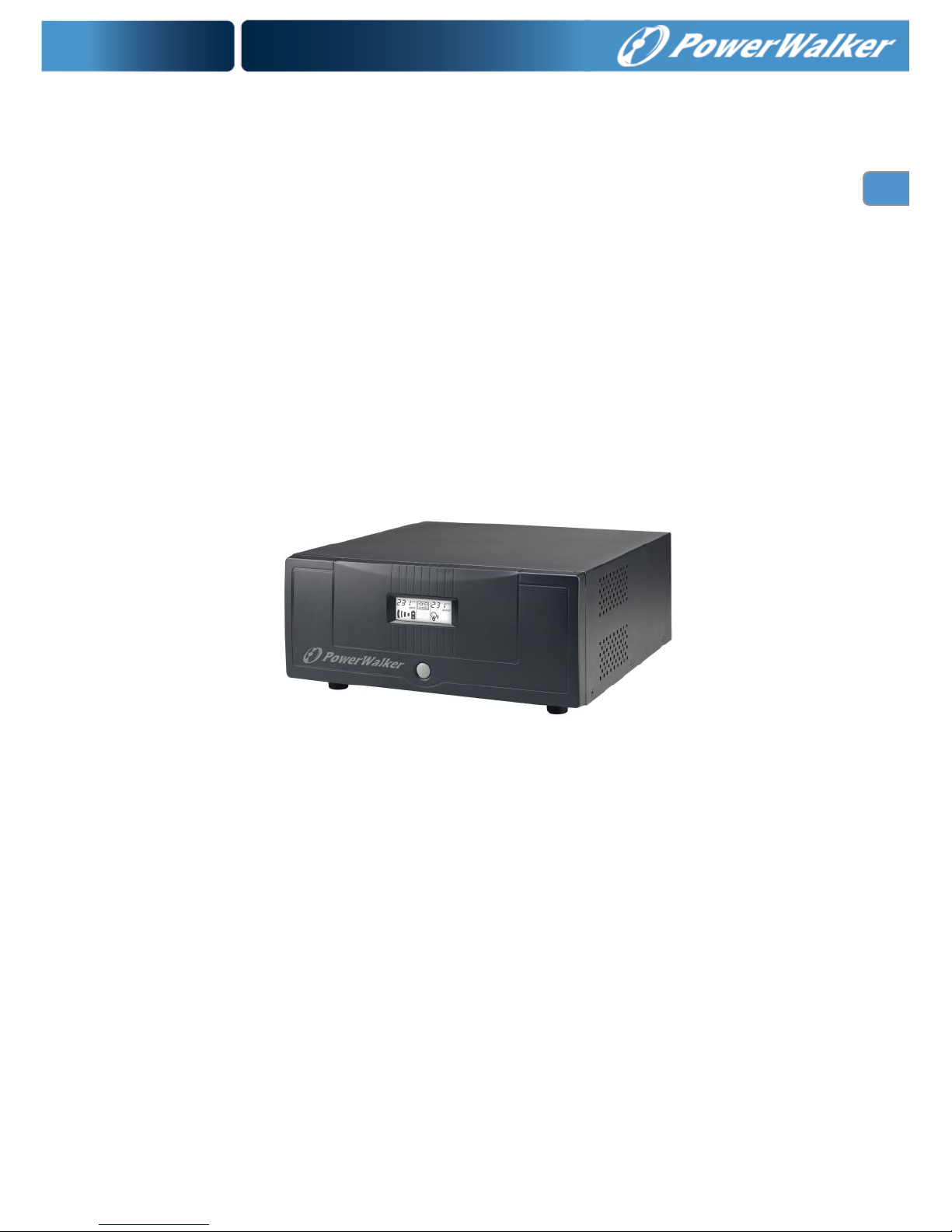
PowerWalker Inverter 700 PSW
PowerWalker Inverter 700 PSW/FR
PowerWalker Inverter 1200 PSW
PowerWalker Inverter 1200 PSW/FR
Quick Start Guide
EN
Page 2

1
EN
1. Introduction
This robust inverter is designed to power your home appliances or precious electronics. It also can
accept wide input voltage to generate stable and pure power source to power downstream AC
loads. Based on different types of loads, this inverter can provide pure and stable power either to
house appliances or to sensitive personal computers via selectable operation modes. It is a brilliant
choice for home owners or small office users in the unstable power area.
PowerWalker Inverter 700-1200 PSW (FR) series provides a variety of features:
Pure sine wave inverter
Selectable input voltage range for home appliances and personal computers
Seletable charging current
Auto restart while AC is recovering
Overload and short circuit protection
Generators & Computer-related devices compatible
Smart battery charger design for optimized battery performance
Cold start function
2. Package Contents
You should have received the following items inside of package:
Inverter Unit
Quick Start Guide
Page 3
2
EN
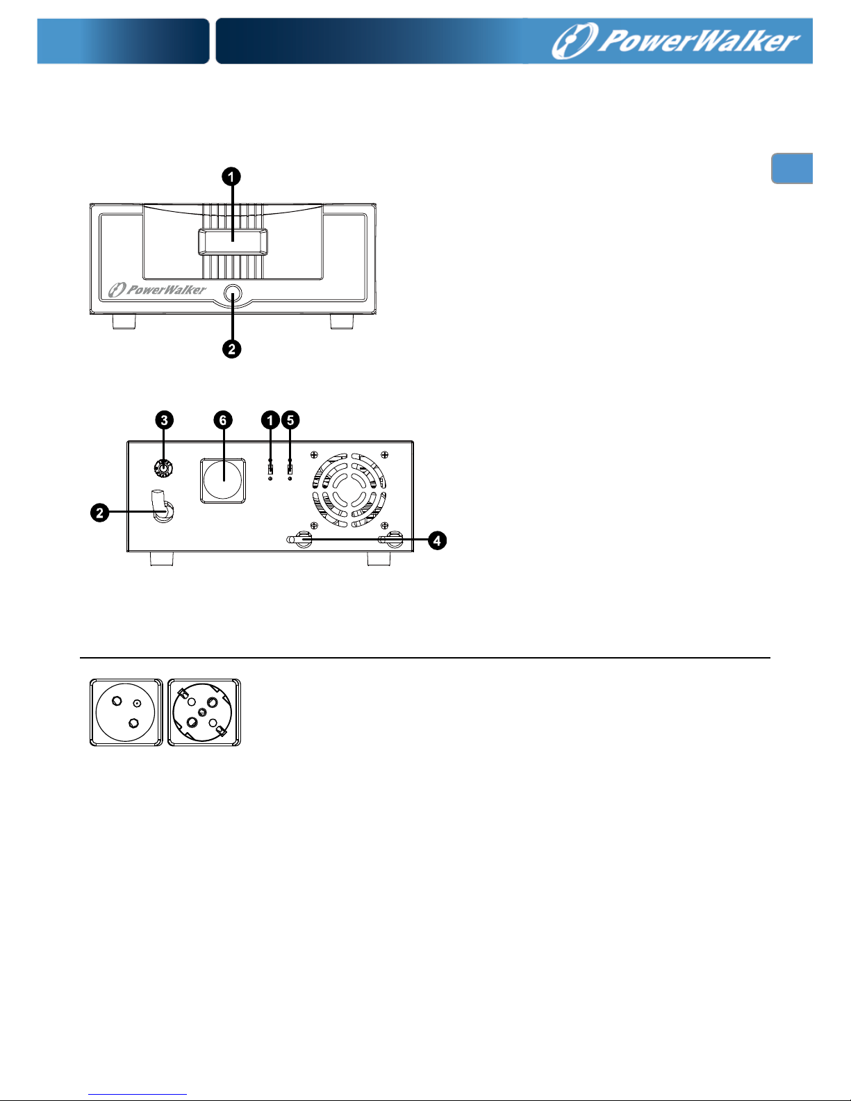
3. Product Overview
Front Panel:
Power switch
Display indication
(please see the Operation section for the details)
Back Panel:
Input voltage range selector
AC input
Input breaker
External battery connector
Charge current selector
Output receptacles
French Schuko
Page 4

3
EN
4. Installation
NOTE: Before installation, please inspect the unit. Be sure that nothing inside the package is
damaged.
I:Connect External Battery
Step 1- Install a DC Breaker in a positive battery line. The rating of the DC Breaker must be at
least 60Amp for 700VA model and 100A for 1200VA model to guarantee safe operation without
interruption. Keep the DC breaker off (Refer to Right fig)
Step 2- Connect battery cables to the external
batteries. To have better performance, the
recommended battery capacity is 100Ah – 200 Ah.
Following battery polarity guide printed near the
battery terminal to connect external batteries!
RED cable to the positive terminal (+);
BLACK cable to the negative terminal (-)
Fig. 1
Note: For the user operation safety, we strongly recommend that you should use tapes to isolate
the battery terminals before you start to operate the unit. When connecting to external
batteries, do not cause any short circuits.
1) Single battery connection (Refer to Fig. 1): When using a single battery, its voltage must be
equal to the Nominal DC Voltage of the unit.
II: Multiple batteries in series connection
(Refer to Right fig)
All batteries must be equal in voltage and amp hour
capacity. The sum of their voltages must be equal to
the nominal DC Voltage of the unit.
Note: when connecting batteries in series connection, it’s necessary to use battery wires at
AWG#8 or above.
II: Multiple batteries in parallel connection (Refer to
Right fig): Each battery's voltage must be equal to
the Nominal DC Voltage of the unit.
Note: when connecting batteries in parallel connection, it’s necessary to use battery wires at
AWG#10 or above.
Step 3- Make sure to connect the polarity of battery side and the unit correctly.
Positive pole (Red) of battery to the positive terminal (+)of the unit. Negative pole (Black)
of battery to the negative terminal (-) of the unit.
Step 4- Take the DC breaker on.
Connect to Utility and Charge
Plug in the AC input cord to the wall outlet. The unit will automatically charge the connected
external battery even though the unit is off.
DC breaker
Page 5

4
EN
5. Operation
Power On/Off
Once the inverter has been properly installed, press the power switch to turn on the unit. The unit
will work automatically. When press the power switch again, the unit will be turned off.
WARNING! The unit may have output power when connected to the utility, even though it is
powered off. To completely cut off the output power, please switch off the unit and disconnect the
unit from the utility.
Input Voltage Range Selector
a). “170V-280V”: setting for precious electronic devices
If you select this mode, the unit's input utility range will be 170~280VAC as normal home UPS.
If the utility is higher or lower than this range, the unit will transfer to inverter mode
automatically. And you can connect the computer systems or other precision home equipment
when you select this operation mode.
b). “90V-280V”: setting for home appliances
If you select this mode, the unit's input utility range will be extended to 90~280VAC. If the
utility is higher or lower than this range, the unit will transfer to inverter mode automatically. So,
you can connect the home equipments, such as light bulb, fluorescent tube, fan, or TV on this
mode.
Caution!! If you select the “90V-280V” mode and connect the computer to the output of the unit,
the computer may reboot if the input voltage is too low to be accepted.
Charging Current Selector
a) High: setting battery charging current at 20A for 1.2KVA, 15A for 700VA
b) Low: setting battery charging current at 10A
Page 6

5
EN
LCD Display & Audible Alarm
Status
LCD Display
Audible Alarm
Line mode
Off
Line mode with charging
battery.
and flashes
Off
Battery mode
Off
Off-mode charging
and flashes
Off
Fault mode
Fault code will be displayed.
Fan is locked: F01
Over temperature: F02
Battery voltage is too high: F03
Output short circuited or Over
temperature: F05
Output voltage is abnormal: F06
Over load time out: F07
Bus voltage is too high: F08
Bus soft start fail Main relay failed
led: F09
Main relay failed: F11
Beep Continuously
sounding.
The unit will shut down
after it’s in fault mode for
15 seconds.
Battery weak at battery
mode.
The mark will flash every
second
Beep once every 1 second
The unit is waning of
overload.
The mark will flash every
second.
Beep once every 0.5 second
Power limitation warning
in Line mode
The mark will flash every
second.
Beep twice every 3 seconds
Fan is locked
Beep three times every second
Battery is over charged
Beep once every 1second
Load level indicator: Battery capacity indicator:
Display
Load Level
Display
Battery Capacity
75%~100%
75%~100%
50%~75%
50%~75%
25%~50%
25%~50%
0%~25%
0%~25%
Page 7

6
EN
7. Trouble Shooting
Use the table below to solve minor problems.
Problem
LCD/ Buzzer
Explanation / Possible
cause
What to do
Buzzer beeps
continuously
Fault code 07.
Overload error. The
inverter is loaded with
more than 110% load
and time is up
Reduce the connected
load by switching off
some equipment.
Fault code 05.
Output short circuited.
Check if wiring is
connected well and
remove abnormal load.
Temperature of internal
converter component is
over 120°C.
Check whether the air
flow of the unit is blocked
or whether the ambient
temperature is too high.
Fault code 02.
Internal Inverter
component over 100°C
Fault code 03.
Battery is over charged.
Return to repair center.
The battery voltage is
too high.
Check if spec and
quantity of batteries are
meet requirements.
Fault code 01.
Fan fault
Replace the fan.
Fault code 06.
Output abnormal
(Inverter voltage below
than 190Vac or is higher
than 260Vac)
1. Reduce the connected
load.
2. Return to repair center
Fault code 08.
Internal components
failed.
Return to repair center
Mains exist but the
unit works in
battery mode.
Input voltage is
displayed as 0 on
the LCD
Input protector is
tripped
Check if AC breaker is
tripped and AC wiring is
connected well.
The mark
on or flash
Insufficient quality of
AC power (Shore or
Generator)
1. Check if AC wires are
too thin and/or too long.
2. Check if generator (if
applied) is working well,
or check if input voltage
range setting is correct
(UPSAppliance)
Unit shuts down
automatically
during startup
process.
LCD and buzzer
will be active for 3
seconds and then
complete off.
The battery voltage is
too low (<1.91V/Cell)
1. Re-charge battery.
2. Replace battery.
Page 8

7
EN
No response after
power on.
No indication.
1. The battery voltage is
far too low. (<1.4V/Cell)
2. Battery polarity is
connected reversed.
1. Check if batteries and
the wiring are connected
well.
2. Re-charge battery.
3. Replace battery.
When the unit is
turned on, internal
relay is switched on
and off repeatedly.
LCD display
flashing.
Battery is disconnected.
Check if battery wires are
connected well.
Input circuit
breaker acted and
no output voltage
on terminal but the
LCD display show
the normal output
voltage
LCD display is
normal
The relay had been
damaged during the AC
short circuit
Return to repair center.
If there is any abnormal situations occur, which doesn't list above, please call the service people
immediately for professional examine.
6. Specifications
MODEL
Inverter 700 PSW
Inverter 700 PSW/FR
Inverter 1200 PSW
Inverter 1200 PSW/FR
CAPACITY
700VA/500W
1200VA/840W
INPUT
Voltage
230VAC
Voltage Range
170-280 VAC (For personal computer);
90-280 VAC (For home appliances)
OUTPUT
Voltage Regulation (Batt. Mode)
230VAC ± 5 %
Transfer Time
10ms typical (For personal computer);
20ms typical (For home appliances)
Waveform
Pure Sine Wave
BATTERY
Battery Voltage
12 VDC
Floating Charge Voltage
13.5 VDC
Maximum Charge Current
10/15Amp
10/20Amp
Recommended Battery Capacity
100 Ah – 200 Ah
PHYSICAL
Dimension(DxWxH) mm
289 x 290 x 127
Net Weight (kgs)
4.5
4.8
 Loading...