

Page 1
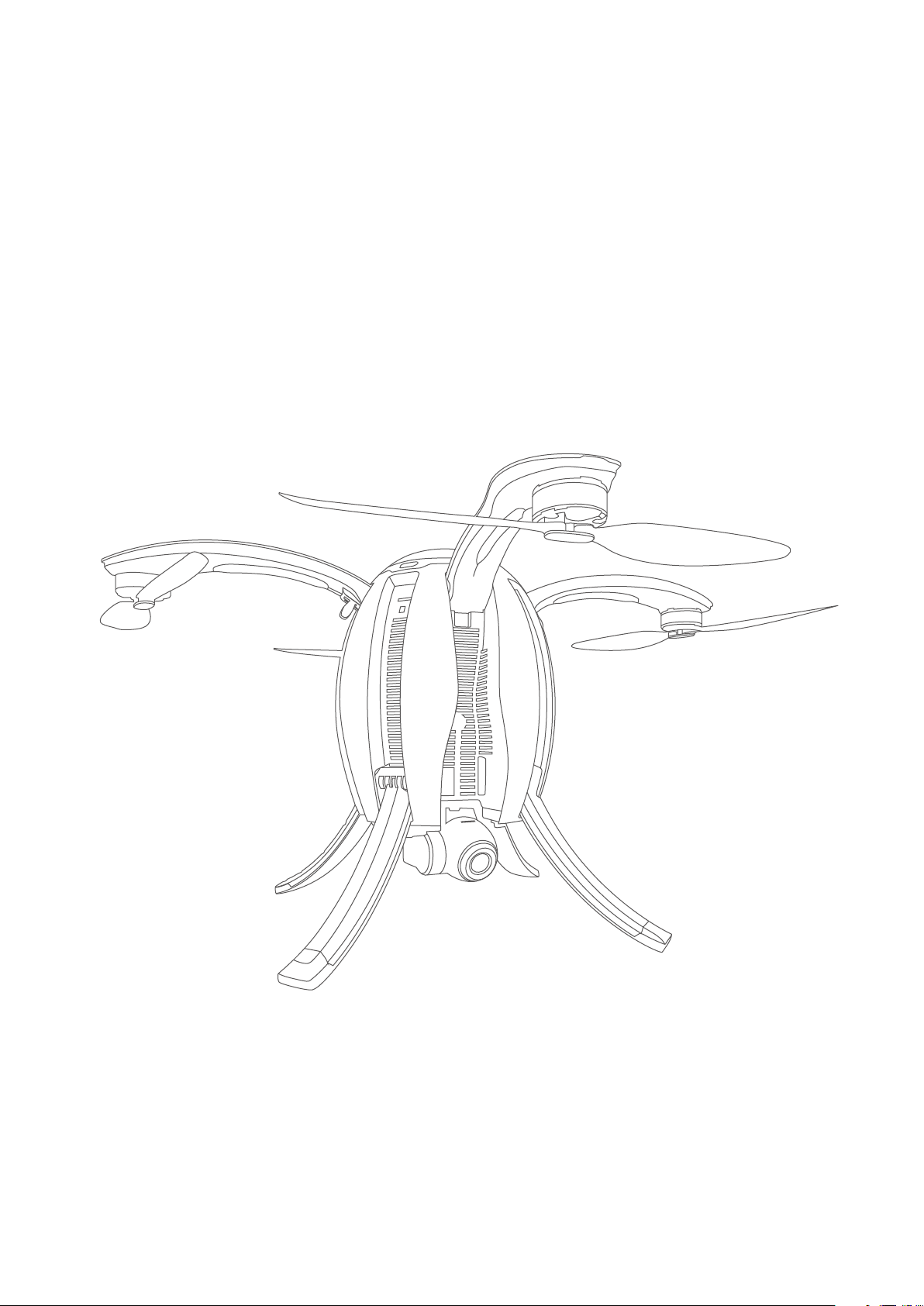
PowerEgg
User Manual
PEGF-E1.1
PowerVision
Page 2

Contents
Product Overview....................................................................................................................1
Introduction.................................................................................................................................1
Feature Highlights......................................................................................................................1
Components of the Aircraft.......................................................................................................2
Components of Remote Controller..........................................................................................3
Preparation of the Aircraft.........................................................................................................6
Preparation of Remote Controller and Base Station.............................................................8
Aircraft..............................................................................................................................................9
Overview of the Aircraft.............................................................................................................9
Flight Modes...............................................................................................................................9
Accessibility...............................................................................................................................10
Aircraft Status Indicator...........................................................................................................14
Description of Aircraft Status Indicator.................................................................................15
Visual Positioning System........................................................................................................16
Propellers...................................................................................................................................18
Intelligent Battery.....................................................................................................................18
Remote Controller................................................................................................................23
Overview of Standard Controller.........................................................................................23
Operation of Standard Controller.......................................................................................24
Standard Controller Turn On/O.................................................................................24
Standard Controller Charge.........................................................................................25
Standard Controller Control.........................................................................................25
Standard Remote Controller Indicator...............................................................................27
Maestro
™ Overview............................................................................................................28
Page 3

Maestro™ Operation..........................................................................................................28
Maestro
Maestro
Maestro
Maestro
™ Turn On/O.................................................................................................29
™ Charge.........................................................................................................29
™ Control.........................................................................................................30
™ Indicator..............................................................................................................32
Base Station.............................................................................................................................33
Overview of Base Station.....................................................................................................33
Operation of Base Station...................................................................................................33
Turn On/O....................................................................................................................33
Connection....................................................................................................................33
Frequency Match of Base Station................................................................................34
Unbind............................................................................................................................35
Charge............................................................................................................................36
Indicator ........................................................................................................................36
Gimbal Camera.....................................................................................................................37
Overview of Gimbal Camera...............................................................................................37
Gimbal Usage.......................................................................................................................37
Introduction to Vision+....................................................................................................38
Product Description.............................................................................................................38
Vision+ Features...................................................................................................................38
Homepage.....................................................................................................................38
Display of Relevant Parameters...................................................................................40
One-click Return Home................................................................................................41
Route Planning..............................................................................................................41
Flight Modes..................................................................................................................42
Return Point Settings....................................................................................................42
Electronic Fencing.........................................................................................................43
Positioning.....................................................................................................................43
Page 4

Layer Switch......................................................................................................................43
Map Direction Lock..........................................................................................................43
Image Transmission..........................................................................................................43
Taking Photos/Shooting..................................................................................................44
Settings.............................................................................................................................44
Media.............................................................................................................................................47
Service...........................................................................................................................................47
Flight..............................................................................................................................................48
Flight Restrictions and Special Area Limited Flight............................................................48
Flight Environment Requirements........................................................................................49
Connection of Aircraft, Remote Controller and Vision+.....................................................49
Compass Calibration..............................................................................................................52
Start/Stop The Motor.............................................................................................................54
Emergency Stop.....................................................................................................................54
Basic Flight..............................................................................................................................56
Page 5

Product Overview
Introduction
PowerEgg is a ight system which consists of an aircraft, a gimbal camera, a standard remote
controller, a gesture-based remote controller, a base station and Vision+, the ight app for iOS or
Android. The user may perform ight over the aircraft by connecting the standard or gesture-based
remote controller to the base station. The aircraft integrates a ight system and an integrated 3-axis
gimbal to facilitate the user to observe high-denition (HD) images transmitted from the camera in
a real-time manner via Vision+ and take photos and video.
Feature Highlights
1.Unique egg-shape design and perfect combination of technology and art.
2.No dismantling required, integrated design, foldable and easy to carry.
3.Operated by an innovative gesture-based remote controller, which enables the user to get started in
one minute.
4.Flight safety built in.
5.360° panoramic shooting with integrated 4K UHD camera + 3-axis self-stabling gimbal to guaran-
tee richer scenes.
6.Top conguration for 5km* UHD image transmission with 23-minute** ight endurance ability.
*The transmission distance may be shorter depending on local laws and environment.
**It’s the maximum time realizable in the testing environment, and it’s for reference only.
01
Page 6
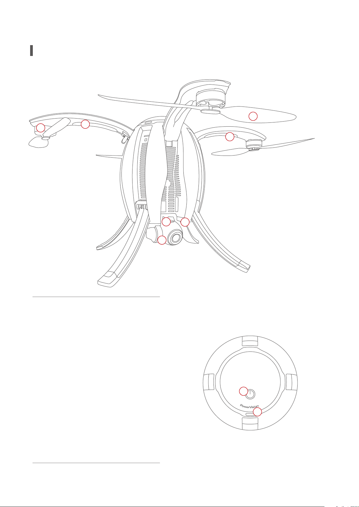
Aircraft
6
7
4
5
1.4K UHD camera on 3-axis gimbal
2.Micro SD card slot
3.Optical positioning sensors and ultr-
asonic positioning system
4.Aircraft front LED indicator
5.Aircraft Status LED indicator
6.Brishless, low friction motor pods
2
1
3
8
7.Propellers
8.Power switch/Landing gear control/
Frequency button
9.Battery compartment access button
9
02
Page 7
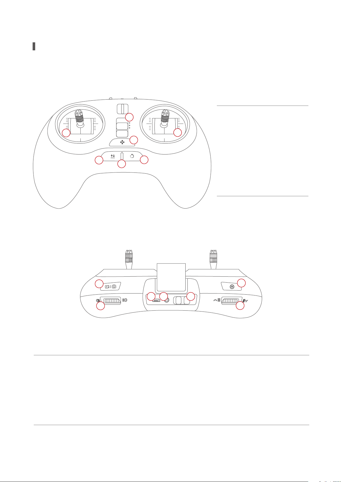
Standard Controller
1
P
N
E
2
3
4
1.Mode switch
2.Left joystick
3.Right joystick
4.Custom button
5
6
7
5.Take o/land/stop landing
6.Status/battery indicator
7.Return-to-home/Cancel
8
13
9
8.Top right button: take photos/videos
9.Right nger wheel: gimbal yaw
10.Micro USB charging port
11.Port: connect to base station
12.Power Switch
10
11
12
14
13.Left top button: gimbal back to position with
short press/sele with double press/
gimbal face downward with long press
14.Left nger wheel: gimbal pitch
03
Page 8
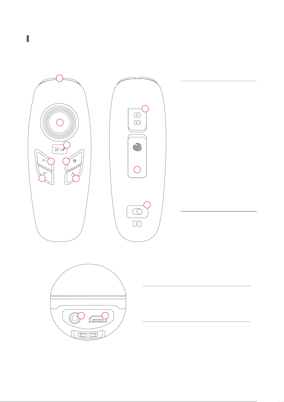
Maestro ™ Gesture-based Controller
1
1.StatusBattery indicator
8
2.Joystick: gimbal control
3.Custom button
2
4.Ascend button
5.Descend button
3
6.Take o/land/stop landing
4
6
7.Return-to-home/cancel
9
8.Take photos/videos
5
7
9.Gesture activation
10.Power switch
10
on off
11
11.Port: connect to base station
12.Micro USB charging port
12
04
Page 9
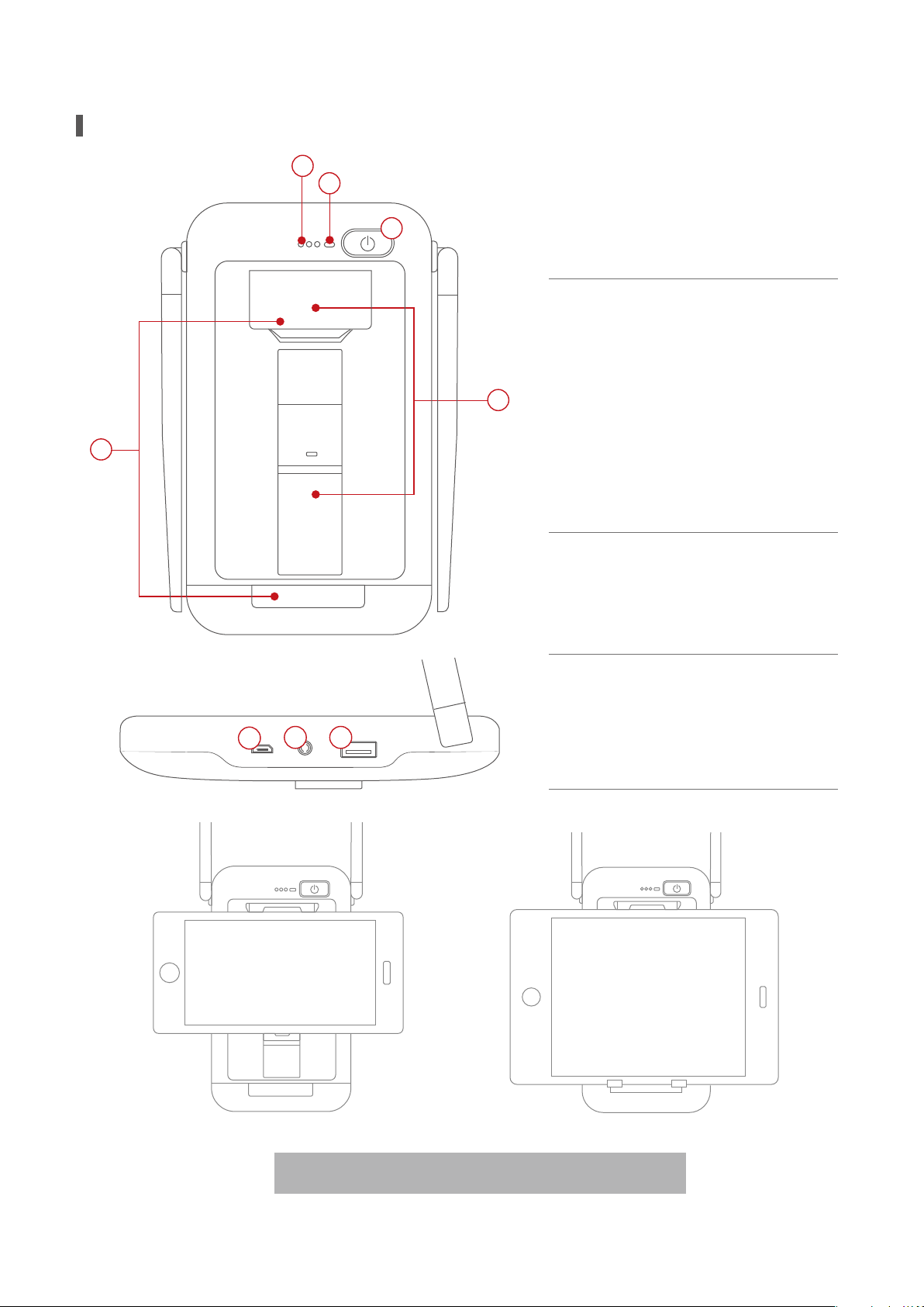
Base Station
2
1
3
1.Battery indicator
2.Image transmitting signal
4
5
6
7
8
indicator
3.Power switch
4.Cell phone connection bracket
5.Tablet connection bracket
6.USB port
7.Port: connect to the controller
8.Micro USB charging port
How to use bracket is presented in the graph.
05
Page 10
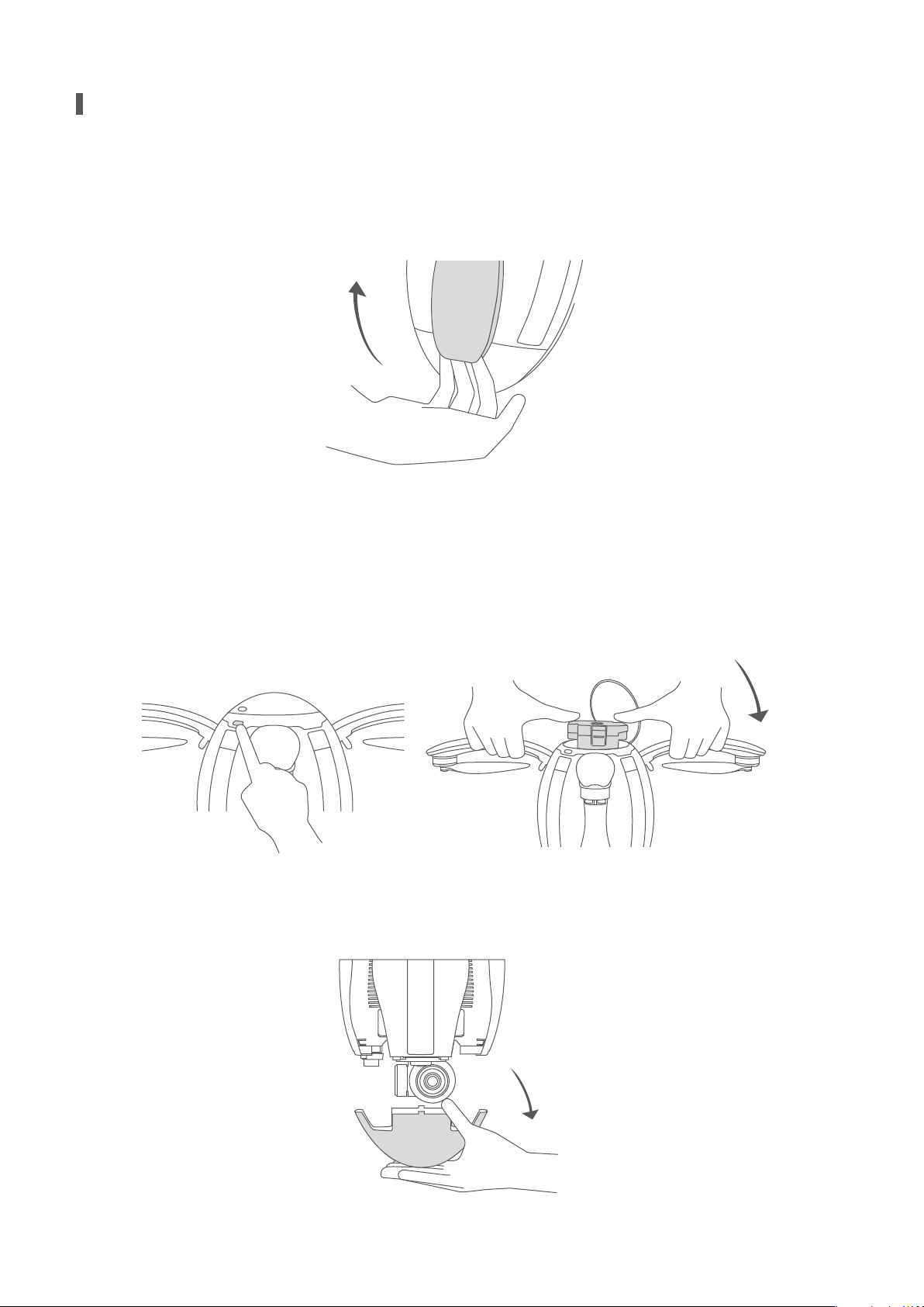
Preparation of the Aircraft
1.Spread the four arms one by one as shown. You’ll hear a clicking sound when the arms are
properly positioned and self-locked.
2.Press the upper cover switch and open the top battery cover. Hold the arms and insert the battery
into the chamber. You’ll hear a clicking sound when the battery ts in the chamber and gets locked.
Note: When replacing the battery while the landing gear is deployed, do not insert the battery
without rst lifting and holding the aircraft. Not doing so may result in your device being damaged.
3.Take o the lower cover. Note: The lower cover must be removed before the unit is powered on,
otherwise the 4K UHD gimbal camera can become damaged.
4K
06
Page 11
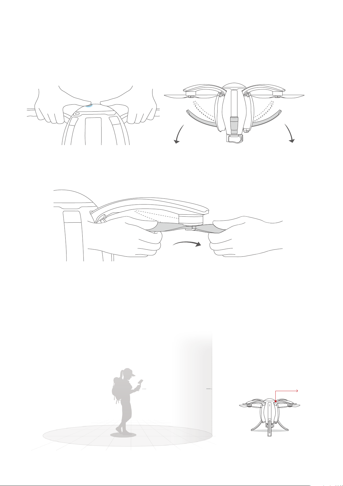
4.First short press and then long press the power button to power on the device. To deploy
the landing gear, quickly press the power switch three times when the blue status indicator of
the aircraft is on.
5.Spread the propellers of the aircraft with both hands.
6.Place the aircraft on the ground surface at least 10m from the pilot, with the head of the
aircraft (indicated by the red lights on the arms) facing the ying direction and pilot facing the
tail (the power button also indicates the front of the aircraft).
Radius of safety:10m
Head direction
07
Page 12
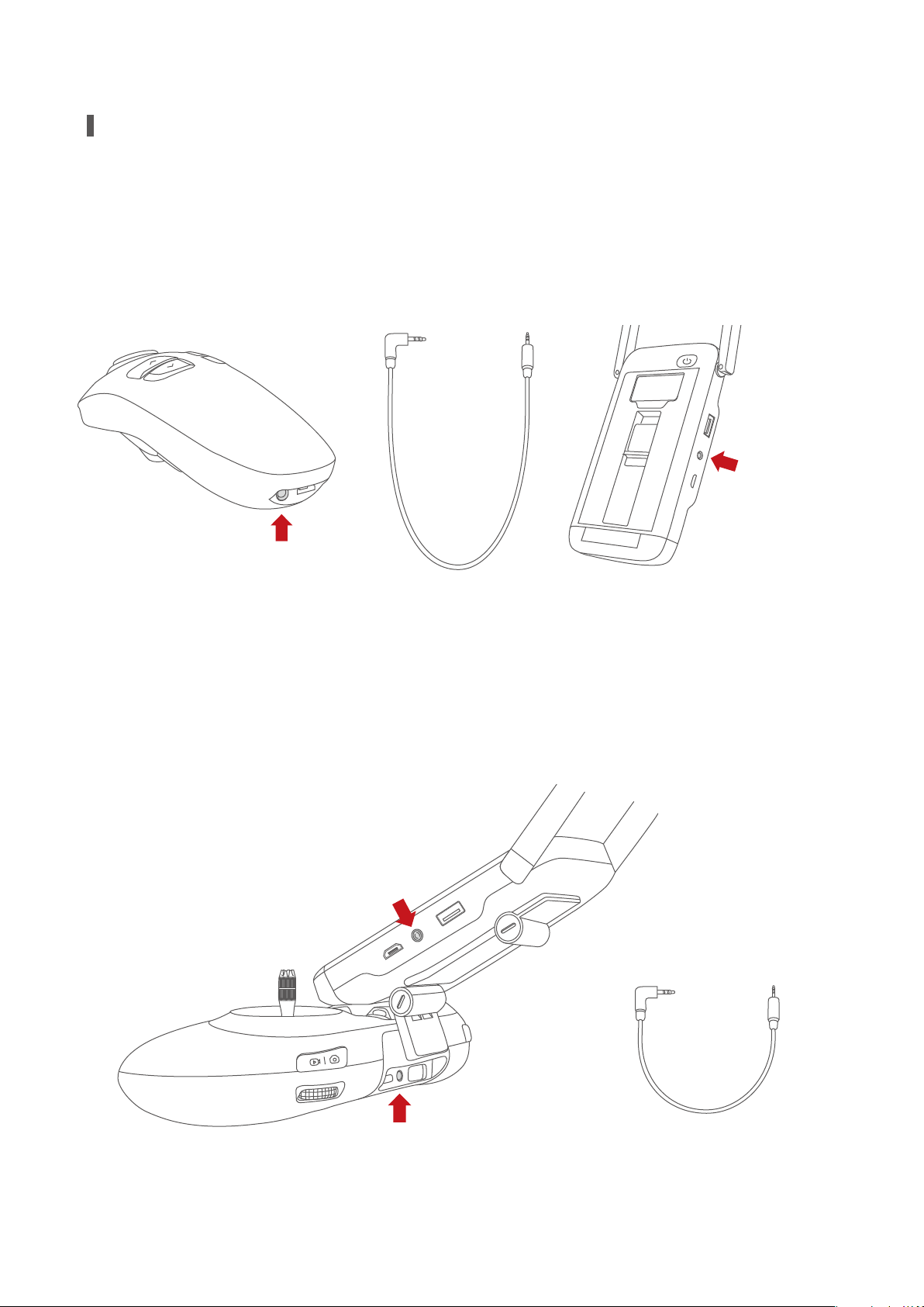
Preparation of Remote Controllers
If the gesture-based remote controller is used for ight control, rst connect the base
station and the gesture-based remote controller with a data cable.
Connect the data
cable to this port
Connect the data
cable to this port
If the standard remote controller is used for ight control, connect the base station to the
bracket of the standard remote controller and connect them through cable.
Connect through this port
Connect through this port
08
Page 13
P
N
E
Aircraft
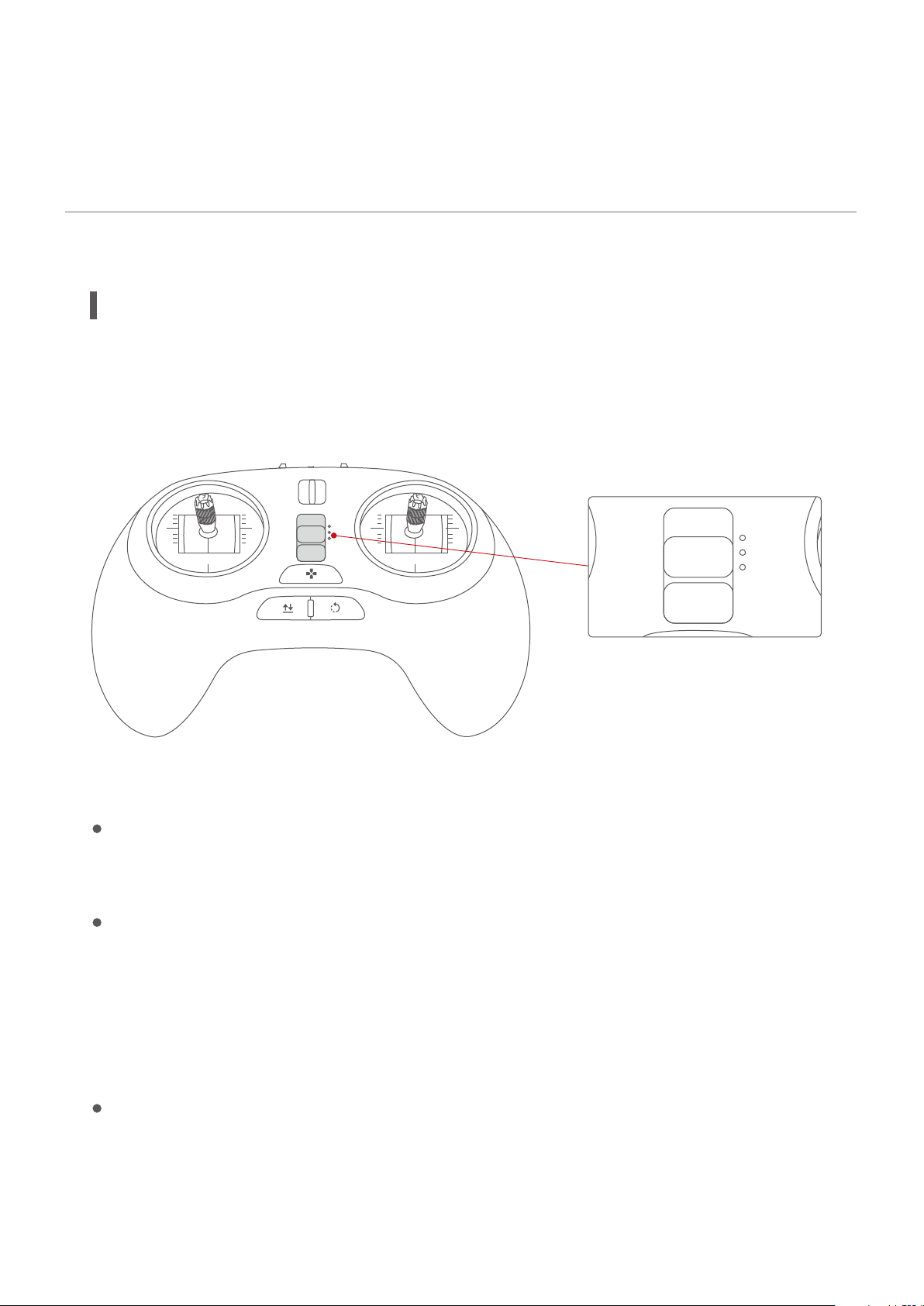
Flight Modes
PowerEgg has three dierent ight modes:
P
N
E
P Mode (Professional): professional ight mode
In this mode, sonar is used instead of GPS and the visual positioning system. The aircraft is essen-
tially on full manual control.
N Mode (Normal): Normal ight mode
In this mode, the aircraft uses GPS or the visual positioning system, depending on their signal
strength. If GPS is unavailable the visual positioning system and sonar are used to ensure accurate
hovering of the aircraft, including indoors. When neither GPS signals nor the visual positioning
system satises the condition for proper and safe ight, the system will automatically switch to
Professional Mode. In this case, only sonar is provided.
E Mode (Easy Control): Super-easy ight mode
In this mode, the aircraft uses GPS and there is no need to focus on the ight orientation of the
aircraft. There is a 10m radius safety zone with the user as the center of the circle, where the
09
Page 14
aircraft cannot enter. The forward and backward ight direction of the aircraft is relative to the
operator. Pushing the right joystick up will move the aircraft away from the operator, regardless of
aircraft orientation.
Accessibility
Automatic take-o
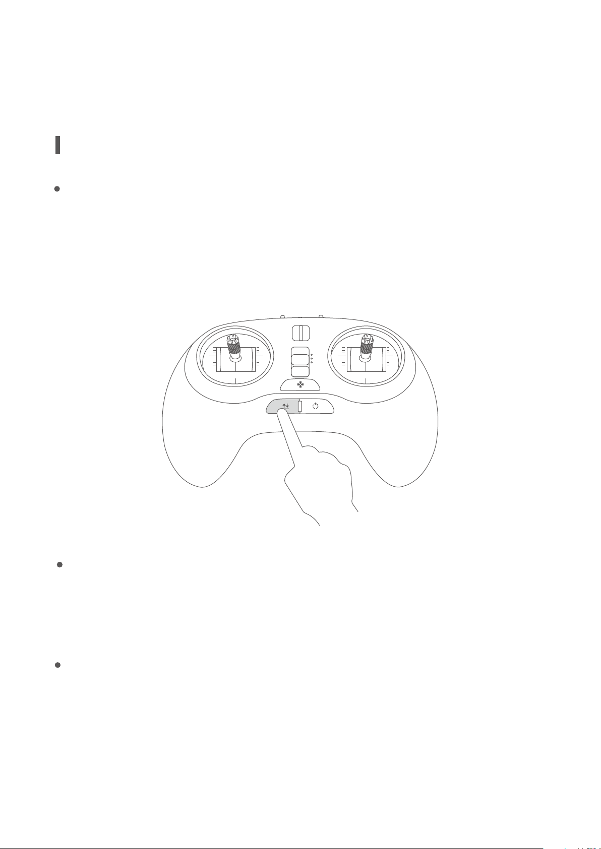
Unlock the aircraft and ensure ight conditions for either via GPS signals or the visual positioning
system meet minimum requirements. Long press the automatic take-o button on the remote
controller until it vibrates. The aircraft ascends to a height of 1.3m above the ground at a set
speed and then automatically hovers in the air.
P
N
E
Automatic landing
Long press the automatic landing button until it vibrates. The aircraft starts to descend at a
set-speed from the current position, subject to horizontal control during descending.
Smart return-to-home
The smart return-to-home mode may be applied only when there is ample GPS signal. In
this mode, the aircraft returns to the return point from the current position (when switched
to the return-to-home mode).
10
Page 15
Smart return-to-home behavior
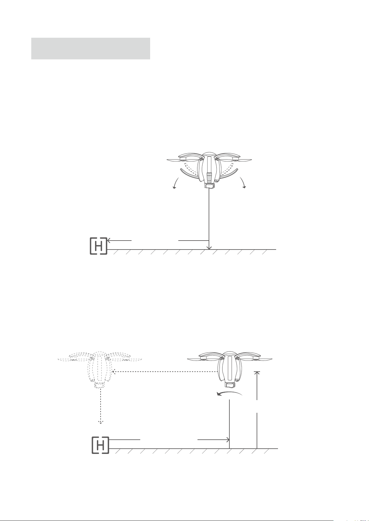
The return-to-home behavior depends on the location of the aircraft when it is switched to
return-to-home mode.
1.When the aircraft is located within 10m horizontally from the return-to-home point, it deploys
the landing gear and automatically lands on the spot.
Return point
Less than 10m
2.If the aircraft ies higher than the return altitude (default value: 20m) beyond 2.10m, it rst makes a
turn to face its head towards the operator, ies to the position above the return point, and then
deploys the landing gear for vertical landing. The location of nal landing can be controlled by the
joystick.
Greater than 20m
Return point
Greater than 10m
11
Page 16
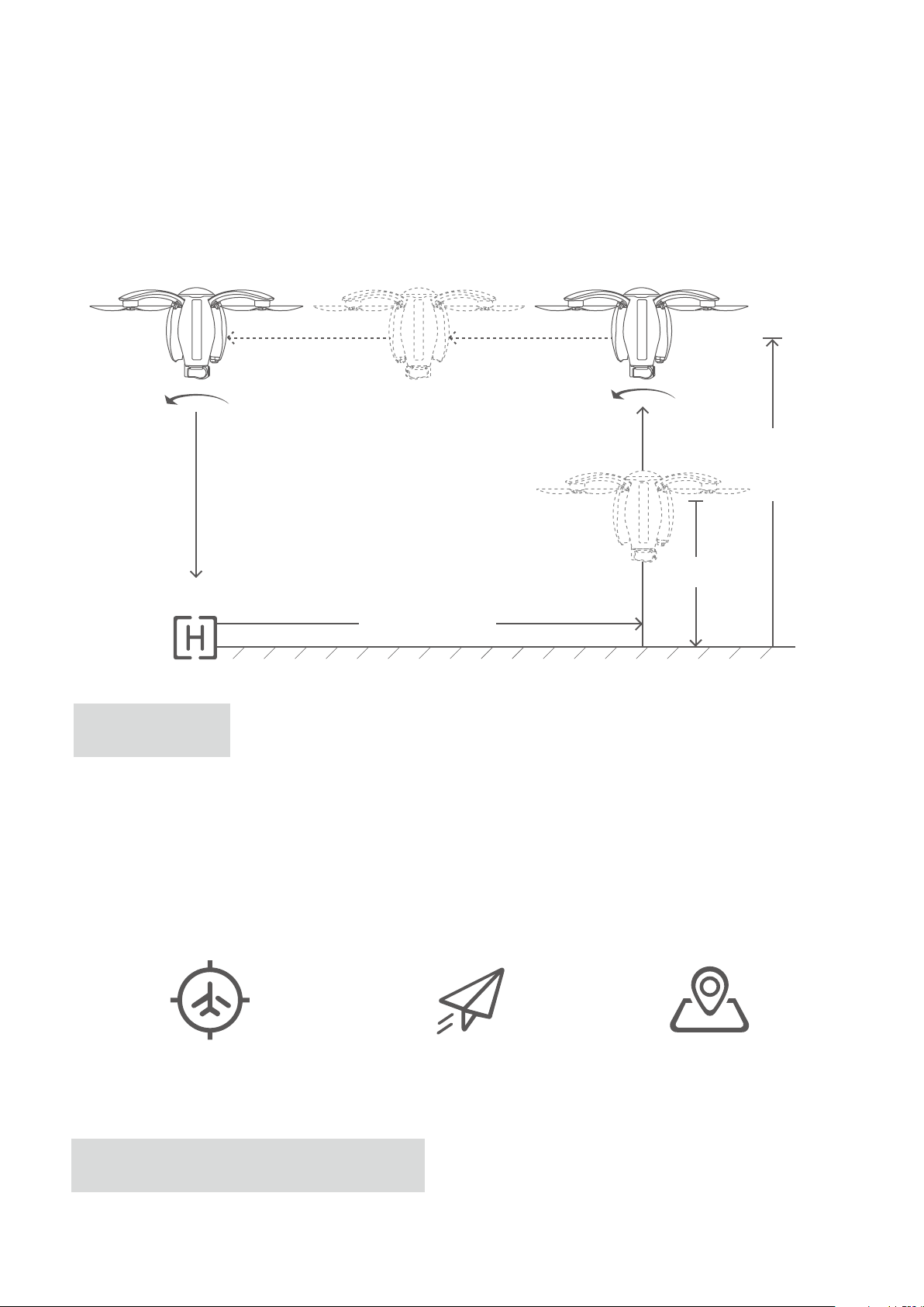
If the aircraft ies lower than the return altitude beyond 3.10m, it rst vertically climbs to the return
altitude, then turns the head to the operator and returns to the point above the return point. Then,
the aircraft turns the tail towards the operator, deploys the landing gear and vertically lands on the
ground. During the nal descent, the location of nal landing can be controlled by the joystick of the
remote controller.
Return point
altitude: 20m
Less than 20m
Return point
Greater than 10m
Return point
There are three kinds of return points: user location, aircraft starting point and map selection point.
The take-o point of the aircraft will be selected as the return point for default when changed in the
Vision+ app. Each time after power cycling the aircraft, the return point will be automatically reset to
the take-o point. Please select a proper return point each time after power cycling.
User location Aircraft starting point Map selection point
Categorization of smart return-to-home
12
Page 17
Smart return-to-home can be realized in three patterns: lost control return, one-click return and low
power return
1.Lost control return
In the case of loss of signal, the aircraft rst hovers in the air and then triggers lost control return in
10 seconds. After gaining signal of the remote controller again, the aircraft switches to the mode
used prior to the loss of signal and continues to y.
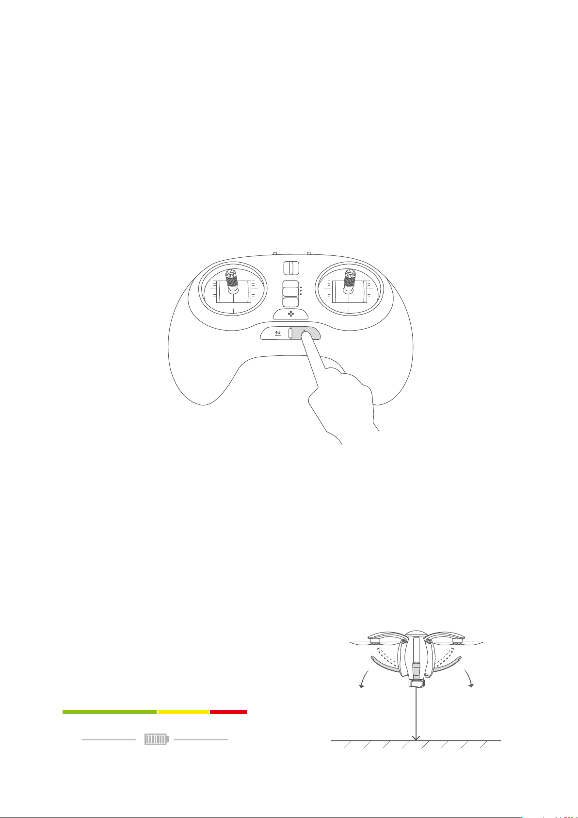
2.One-click return
Long press the return-to-home button on the standard remote controller to trigger one-click return.
Short press the button to cancel return-to-home. The aircraft can operate at dierent horizontal
positions via the joystick of the remote controller during the descending process.
P
N
E
3.Low-battery return
When battery level of the aircraft drops to a predetermined level, Vision+ will pop up a message for
the user to decide whether to trigger low-battery return. Click “Yes” to return the aircraft. Return can
be terminated by pressing the automatic Return-to-home key on the standard remote controller.
During the descending process, the user may manipulate the joystick to change the position of the
aircraft in horizontal direction so that it can land in a safe zone.
Note: The aircraft may have obstacles in its path during return-to-home. The user needs to detect
such obstacles via visual observation or image transmission, and avoid these obstacles by means of
ending the return-to-home process or adjusting ight height of the aircraft.
Battery level
LowFull
13
Page 18
Orbit mode
While ying with GPS, the aircraft ies at a height of 10m above the ground. Specify the center
of a circle via Vision+ and manipulate the aircraft to y to any position 10m beyond the center of
the circle. Set the orientation via Vision+ and start the circling mode. During circling, the head of
the aircraft will always point at the center of the circle.
Sele mode
While ying with GPS, the user only needs to press the Sele button on the gesture-based remote
controller when the aircraft is ying. The head of the aircraft will automatically aim at the user.
Waypoint mode
While ying with GPS, the user may set a ight waypoint via Vision+ and the aircraft will y on the set
waypoint trajectory.
Follow-me mode
While ying with GPS, the aircraft can follow the standard or gesture-based remote controller and
move correspondingly at a certain distance, with the ight height adjusted by the remote controller.
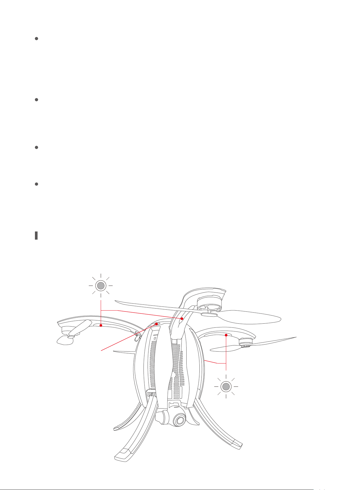
Aircraft Status Indicator
Each arm of PowerEgg has a head indicator (head lamp) and an aircraft status indicator (tail lamp).The
following gure indicates the specic locations of the indicators.
Head indicator
Power key
Tail status indicator
14
Page 19
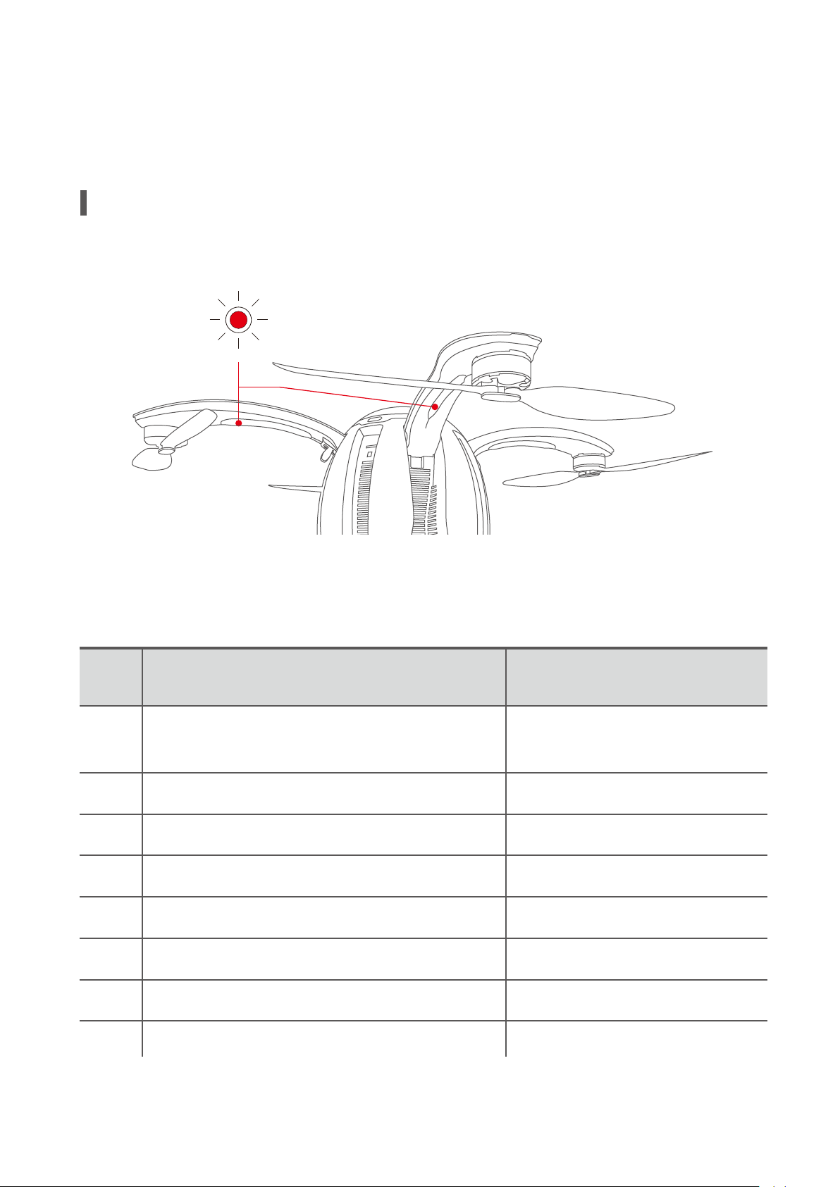
The head indicator is used to identify the head direction. When the power of the aircraft is turned
on, the indicator is normally on and lights in red. The tail indicator gives information about status of
the aircraft, with dierent ashing modes indicating dierent statuses.
Description of Aircraft Status Indicator
The head indicator is red when the aircraft is powered and the system is operating normally.
Head status indicator
The tail indicator LEDs provide status information on the aircraft back to the
operator:
S/N Description
Systems check during power-on: successful
1
2
3
4
5
6
system check
Failed system check
GPS signal acquired or optical ow is functioning
No sucient GPS signal or optical ow is not functioning
P Mode (Professional) after motor startup
N Mode (Normal) and other accessibility mode
Flashing process of Status
Indicator
Alternative ashing in red,
green and blueonce
Slow ashing in red
Slow ashing in green
Slow ashing in yellow
On in yellow
On in green
7
8
E Mode (Easy Control)
Trigger landing gear deploy/withdraw
On in white
Quick ashing in yellow
15
Page 20
9
Shutdown process
Quick ashing in white
10
11
12
13
Code matching of remote controller
Alarm of low battery or loss of signal of remo-
te controller
Successful mode switching; successful task
execution; successful sensor calibration
In a no-y zone where take-o is forbidden
Slow ashing in blue
Slow ashing in red
Flashing in green
Slow ashing in red
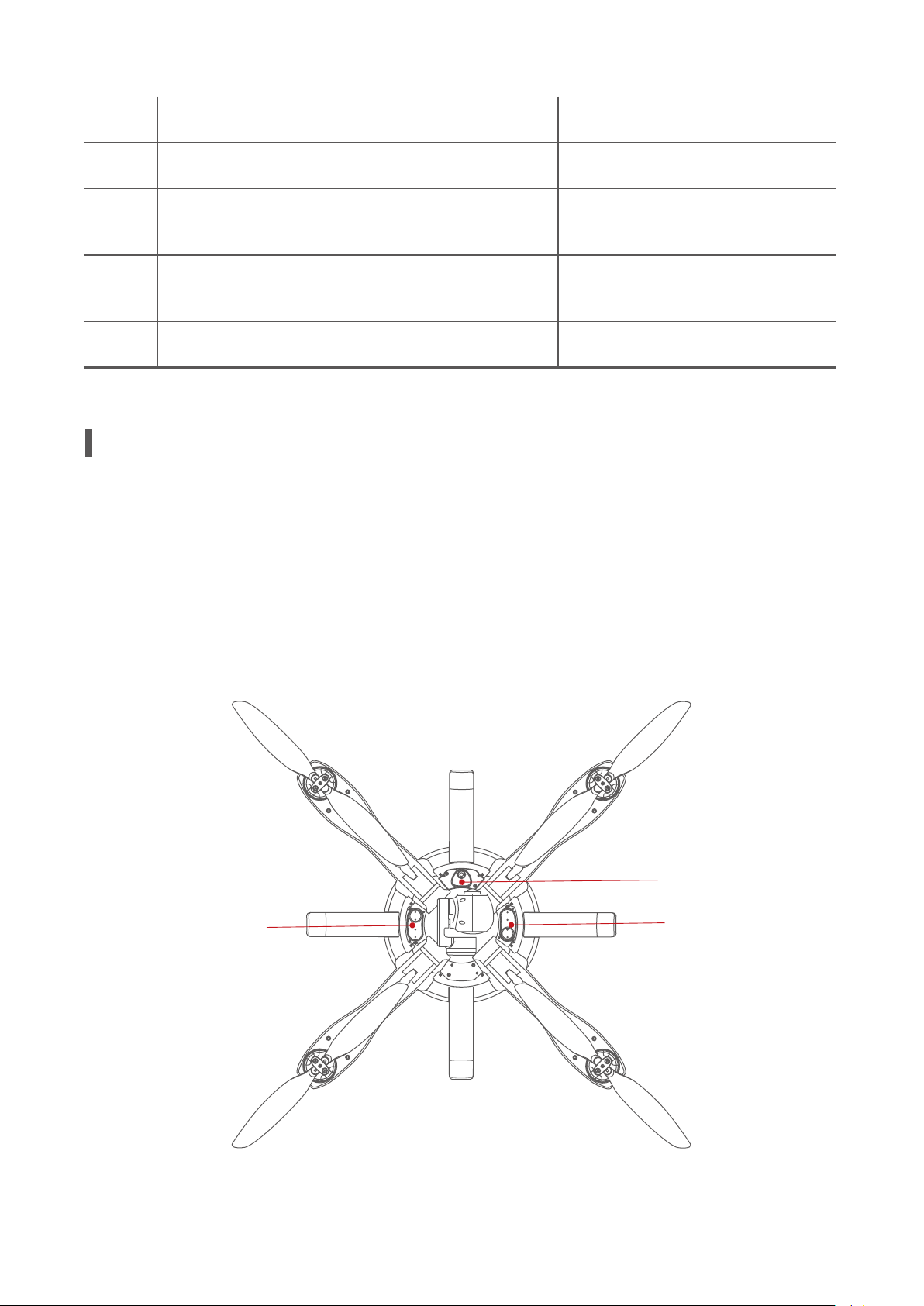
Visual-aided Positioning System
The visual-aided positioning system is ultrasonic and camera based, with the camera obtaining
the current position of the aircraft and ultrasonic wave used to measure the altitude so as to
achieve accurate hovering and positioning of the aircraft. The visual-aided positioning system is
located at the bottom of the aircraft, as shown in the gure below, and consists of two modules:
ultrasonic and optical ow.
Ultrasonic
Optical ow
Ultrasonic
16
Page 21
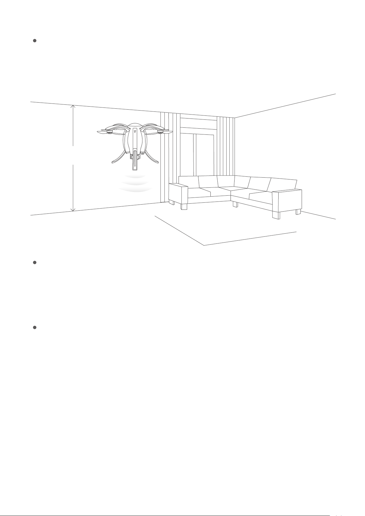
Optical ow positioning system
The optical ow positioning system applies to any environment having a height not greater than 3m
and with weak or no GPS signals, particularly for indoor ight. See the gure below.
Less than 3m
Using steps of the optical ow positioning system
1.Switch the remote controller to N Mode: normal ight mode.
2.Turn on the power. The aircraft status indicator will be green.
3.The aircraft takes o. The optical ow positioning system will hold the aircraft in position.
Scenarios that may contribute to failure of the optical ow positioning system
1.When the aircraft takes a low-altitude ight (below 0.5m) at a rapid speed, the optical ow posi-
tioning system may fail to locate the aircraft.
2.Solid color plane.
3.A strongly reective, reective, water or transparent surface (such as glass oor, ice surface and
lake surface).
4.Flying with excessive speed (exceeding 3m/s at 1m above the ground or 6m/s at 2m above the
ground).
5.Surface of a moving object (over grass, crops and bushes blown by wind or over a crowd).
6.An extremely dark (the range) or bright (range) environment.
7.A surface that is highly absorptive to ultrasonic waves (e.g. thick carpet and elastic cotton).
8.A surface with sparse texture.
17
Page 22
9.A surface with highly repeated textures (e.g. black and white lattice tiles).
10.Any slopes steeper than 30º can impede the receiving of ultrasonic waves.
Precautions
1.Ensure the lens of the optical ow positioning system is clean before ight.
2.The optical ow positioning system only operates up to an altitude of 3m.
3.The optical ow positioning system obtains information depending on ground surface images.
Please ensure that surrounding environment is well lit and the ground texture is rich.
4.The optical ow positioning system cannot function normally on water, in a dark environment, or
where there is no clear ground texture.
5.The ultrasonic waves emitted from the optical ow positioning system can upset animals. Ensure no
animals are in the proximity when the system is in operation.
Propellers
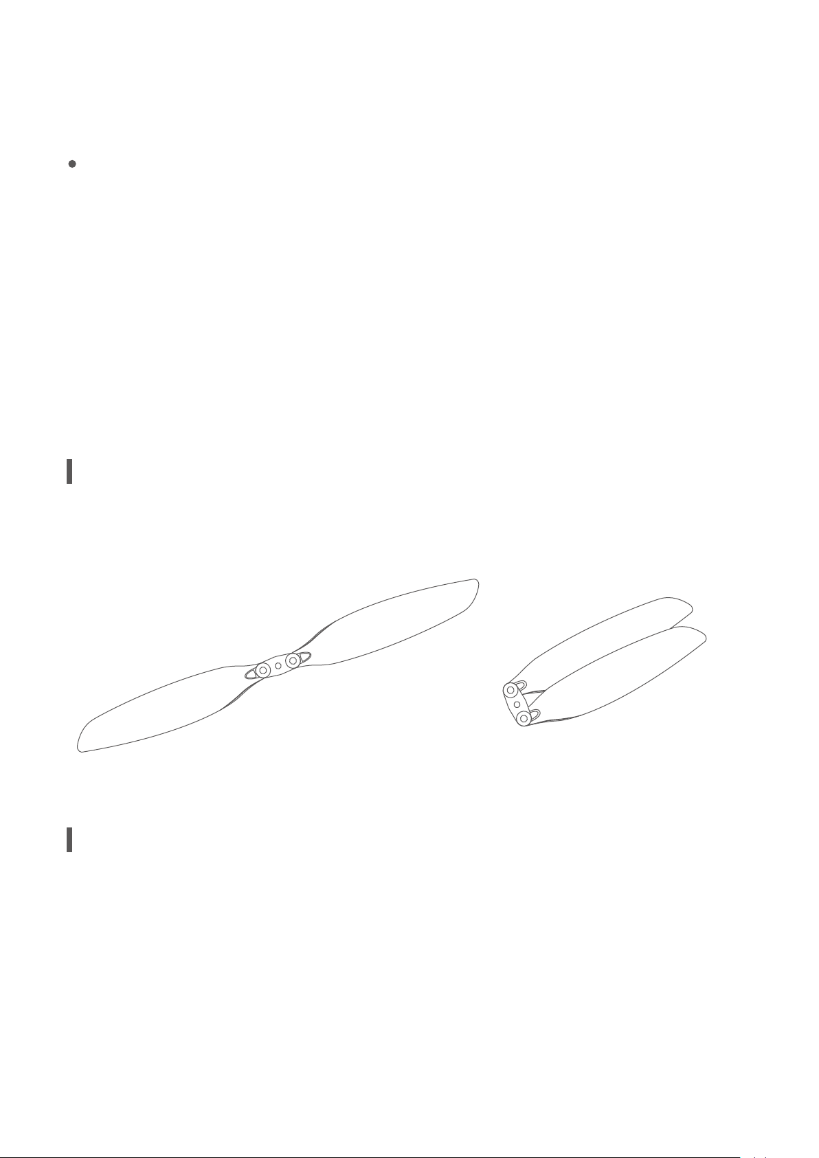
PowerEgg uses customized high-performance 10.5-inch folding propellers.
Intelligent Battery
PowerEgg is equipped with a specially designed smart ight battery which has a capacity of 6,400
mAh, operates at a voltage of 14.8V and has charging-discharging management capabilites. The
battery consists of high-energy cells and an advanced battery management system to guarantee
adequate power supply to the aircraft. The intelligent battery must be charged using the special
charger supplied by PowerVision.
18
Page 23
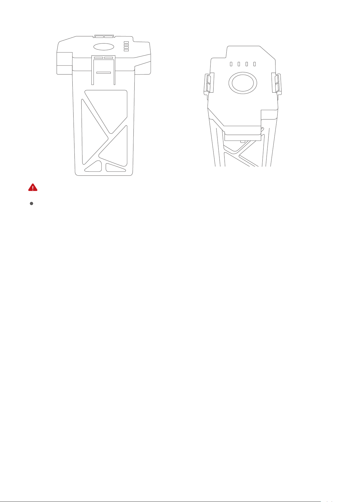
Make sure the intelligent battery is fully charged before its rst use. Please refer to “Battery charging” for details.
Functions of the intelligent battery
The intelligent battery has the following functions:
1.Battery status display: the battery has a status indicator to indicate current status of the battery.
2.Battery life display: the battery has a status indicator to indicate life of the battery.
3.Self-discharging protection for battery storage: if the battery is stored for 10 days without any opera-
tion when its battery level is higher than 65%, it can trigger the self-discharging function to lower the
battery level to 65% for the protection of the battery. The self-discharging process may last for about
two days with no LED indication. The battery may heat up slightly, which is normal.
4.Balance charging protection: cell voltage of the battery can be automatically balanced to protect
the battery.
5.Overcharging protection: Charging will be automatically stopped when the battery is full.
6.Charging temperature protection: the battery will be damaged if it is charged at a temperature
lower than 0℃ or higher than 40℃. This function is to ensure the battery will not be charged at such
temperatures.
7.Overcurrent protection during charging: heavy current charging can severely damage the battery.
Charging will be stopped if the current exceeds 8A.
8.Over-discharging protection: over-discharging can severely damage the battery. The battery output
will be cut o if it is discharged to 12V.
9.Short-circuit protection: the output will be cut o to protect the battery if short-circuit is detected.
10.Cell damage detection: a warning for battery damage will be sent out if cell damage or signicant
cell imbalance is detected.
11.Records of use exceptions of the battery: the app can provide the records of the last 31 times of use
19
Page 24
exceptions of the battery, including battery short-circuit, excessive discharging current, etc.
12. Sleep protection: the battery will enter into sleep if it is not connected to any electrical equip-
ment 20 minutes after it is turned on.
13. Communication: the aircraft can acquire real-time information of the battery through the com-
munication interface on the battery, including voltage, battery level and current.
Please carefully read and abide by the requirements of PowerEgg provided in this manual, the disclaimer
and the tag on the battery before use. The user shall assume the consequences for not using the battery
as instructed.
Battery Usage
Installation: The battery is installed with wrong plug-in protection design, so there is no need
to worry about which way to plug in.
Turn-on: insert the battery into the aircraft. Short press once and then long press once in the
shutdown mode. Turn on the battery to supply power to the aircraft.
Turn-o: Short press once and long press the power button of the aircraft once to turn o
the battery.
Battery level checking: touch the key switch (less than 2s and then release it). The LED indic-
ator will indicate the battery level.
20
Page 25
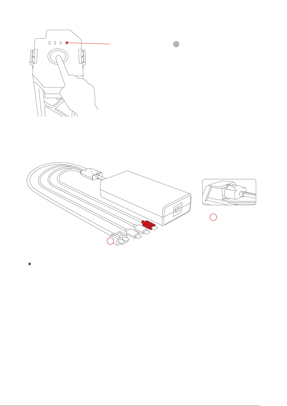
Battery level indicator
Lightly touch the key on the top of the battery to light the
four white indicators. The number of indicators indicates
the charge level.
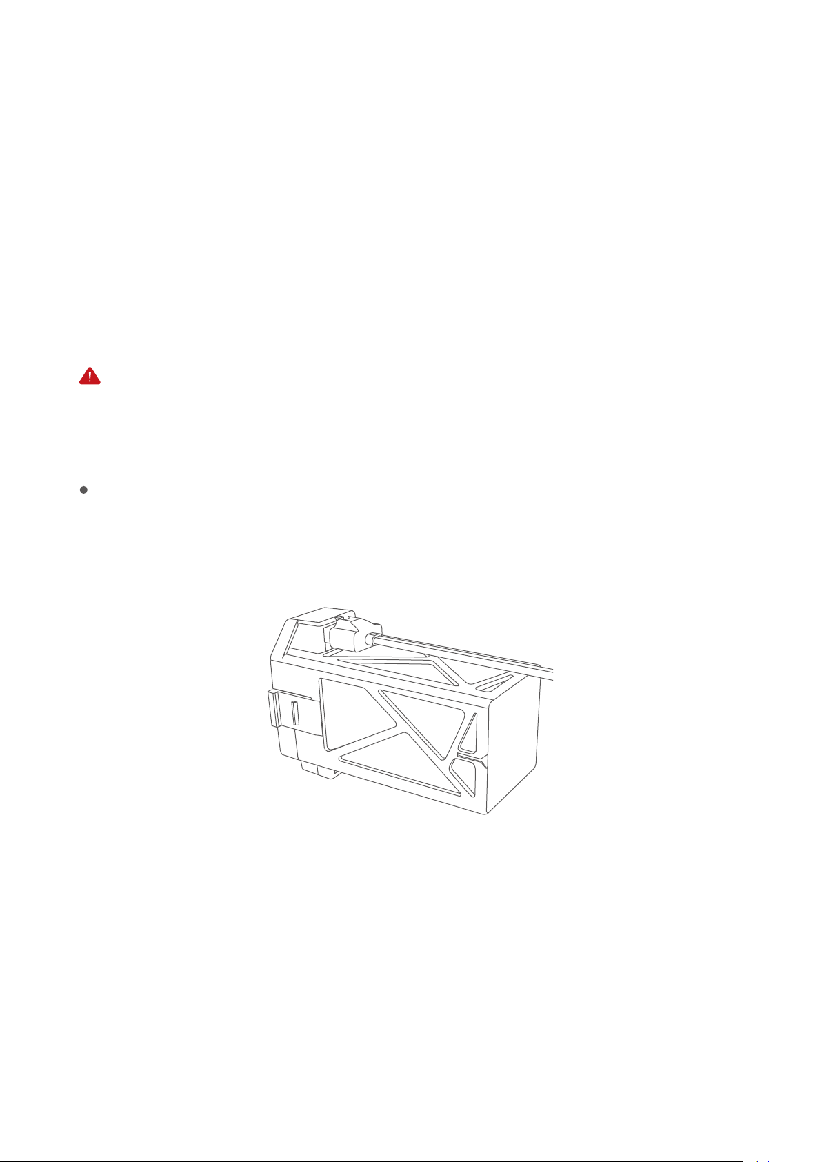
The battery of the aircraft must be charged using the special charger supplied by
PowerVision. PowerVision takes no responsibility for the consequences of using any other
chargers.
Each indicator represents ab-
out 25% of total battery level.
1
2.5 hours for full charging
1
Precautions for use at low temperatures
1.The use of the battery at low temperatures (-10℃ to 5℃) will lead to abrupt reduction in battery
capacity and thus signicant reduction in ight duration of the aircraft. When battery temperature
is between -10℃ and 5℃, the aircraft cannot take o unless a certain voltage is satised. Please
fully charge the battery and take thermal insulation measures for the battery before use.
2.It’s not recommended to use the battery at ambient temperature lower than -10℃.
3.It is suggested to end the ight when a low-voltage warning is sent from the PowerEgg Ground
Station in a cold environment.
4.It is suggested that the battery be preheated to over 5℃ at the minimum, or over 20℃ ideally,
before the aircraft takes o in a cold environment.
Battery
21
Page 26

Battery charging
1.Connect the charger to an AC power source (100-240V, 50/60HZ; use a power converter if neces-
sary).
2.Connect the battery to the charger, with the battery turned on or o.
3.During charging, the battery status indicator will keep ashing and indicate current battery level.
4.The battery is fully charged when all indicators go o. After charging, please remove the battery
from the charger.
5.The battery will be warm after a ight, and should not be charged until it is cooled down to ambi-
ent temperature.
6.The optimal temperature range for charging is 0℃ to 40℃. Charging will be denied by the battery
management system if cell temperature is not within this range.
Use a standard charger to charge one piece of equipment each time. Ensure the battery is turned o before it is
installed into or removed from the aircraft. Do not insert or remove the battery when it is turned on.
The smart battery must be charged using the special charger supplied by PowerVision.
PowerVision will take no responsibility for the consequences of not using the chargers
provided by PowerVision.
Precautions for traveling with PowerVision
1.Ensure that the battery is discharged to a level below 5% before carrying it onto a plane. Keep the
battery away from heat sources before discharging. Ensure the battery is separated from the
aircraft.
2.Keep the battery separate and away from any metal object.
3.Retract the landing gear and fold the arms back to the main body. Install the gimbal cover to x
the 4K UHD camera.
4.Place the aircraft in a packing bag.
22
Page 27

Remote Controller
Overview
This section describes the functions of the remote controllers as well as the way of controlling the
ight of the aircraft and taking photos with the camera. Two types of remote controllers are available
for PowerEgg: standard controller and gesture-based “Maestro”. The gesture-based remote control-
ler requires GPS positioning and thus cannot be used for ights indoors or in other environments
with weak or no GPS signals.
Overview of Standard Remote Controller
PowerEgg standard remote controller integrates one-click takeo and landing, one-click
return-to-home, open and close of the landing gear, control of gimbal pitch and control of gimbal
yaw, one-click back to position and one-click facing downward, taking photos and video shooting
with the 3-axis gimbal. The built-in rechargeable battery in PowerEgg standard remote controller
has a capacity of 3,000mAh and can continuously work for 20 hours. The current battery level may
be checked via the battery level indicator.
The standard remote controller has a built-in GPS receiver. Easy Control mode is available to the
aircraft and the remote controller only when the GPS signal is good, otherwise the aircraft cannot
be started.
When the GPS signal of the aircraft and the signal of positioning or visual aids system is good (the
green indicator ashes slowly), the aircraft may y in Normal mode.
Compliance version: PowerEgg remote controller complies with both CE standards and FCC stan-
dards.
Mode of remote control: The remote controller has Mode 1 and Mode 2, and may be self-dened in
Egg Vision+. Beginners are suggested to operate in Mode 2.
Mode 2: The joystick for the control of up/down is the left joystick of the remote controller.
Mode 1: The joystick for the control of up/down is the right joystick of the remote controller.
23
Page 28
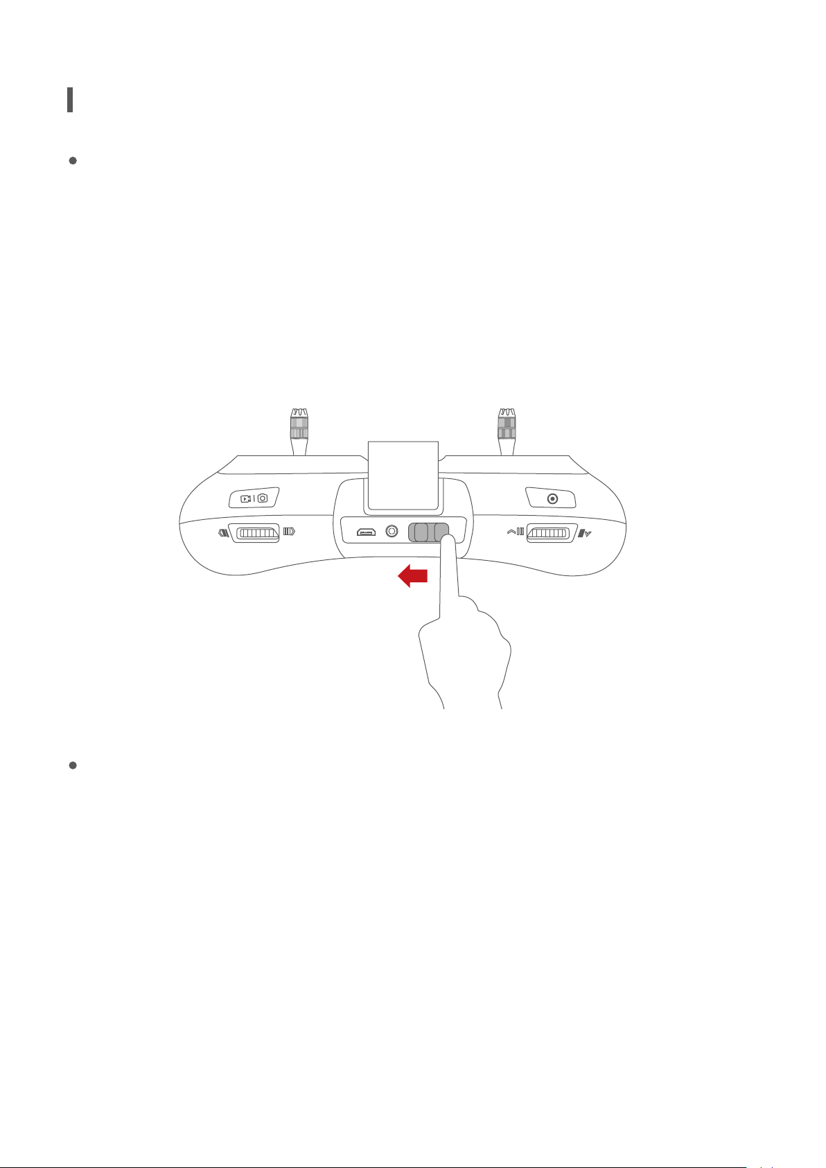
Operation of Standard Remote Controller
Startup and shutdown of standard remote controller
The remote controller may be started by sliding the power switch from the left to the right. The
connection status of the remote controller may be distinguished according to the notication tone of
the remote controller. When the remote controller plays music for 1 second, it indicates that the com-
munication connection between the remote controller and the aircraft is successful. Slide the power
switch from right to left to shut down the remote controller.
Switch on the power switch
Charging of standard remote controller
1.Connect the charger to AC power supply (100-240V, 50/60HZ; use a power conversion plug when
necessary)
2.Connect the battery to the charger, with the battery turned on or o.
3.During charging, when the standard remote controller is shut down, the battery level indicator will
turn red and then turn green when it is fully charged.
4.During charging when the standard remote controller is on, the battery level indicator will show the
battery level of the lithium battery:
24
Page 29
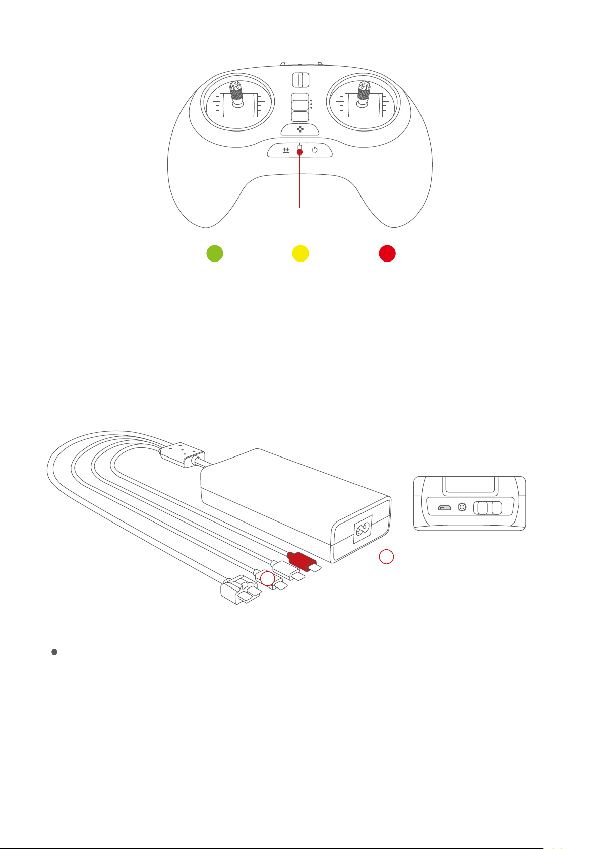
P
N
E
Battery level indicator
Less than 10%10%-30%More than 30%
The battery of the remote controller should be charged with the special charger ocially desig-
nated by PowerVision, which will not be liable for any consequences caused by charging the
battery with the charger not ocially provided by PowerVision.
2
Standard Remote Controller
2
3.5 hours for full charging
Control of standard remote controller
Left joystick: Up and down control the upward and downward movement of the aircraft; left
and right control the horizontal rotation of the aircraft.
Right joystick: Up and down control the forward and backward movement of the aircraft; left
and right control the left and right movement of the aircraft.
25
Page 30
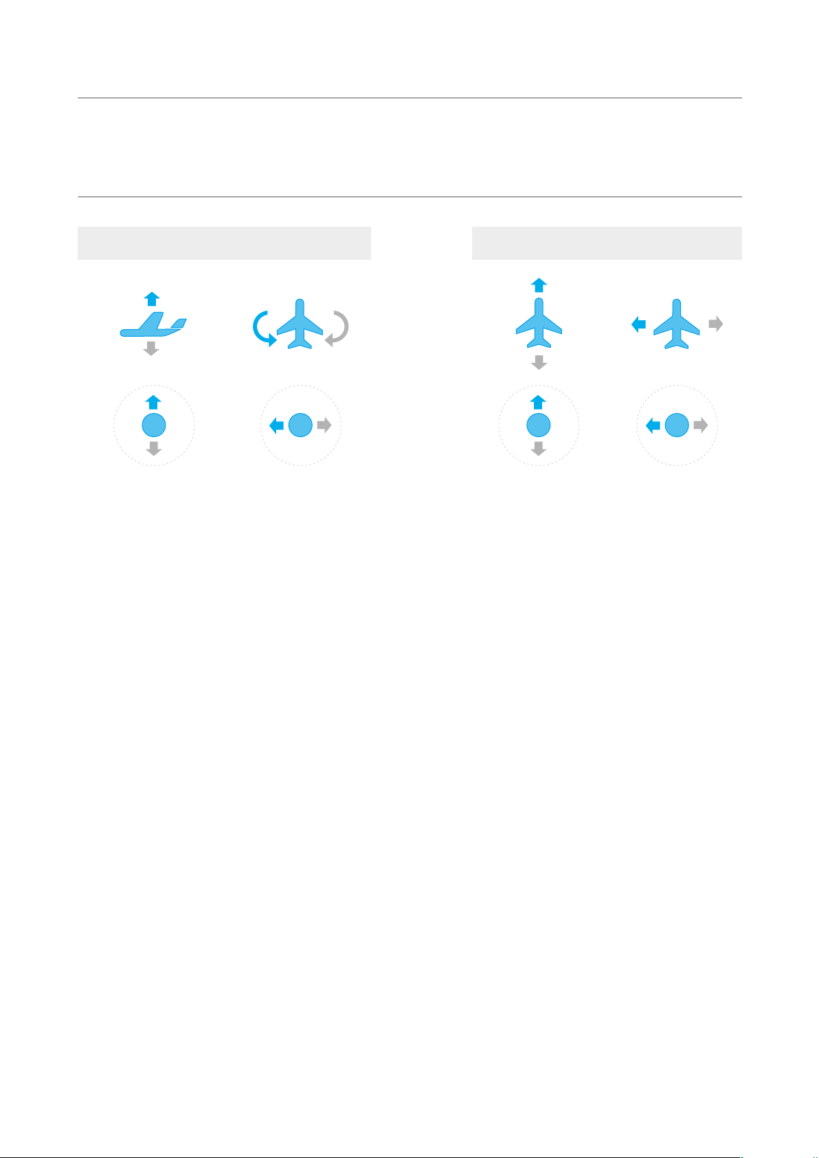
Mode 2: The left joystick of the remote controller controls the up/down of the aircraft.
Mode 1: The right joystick of the remote controller controls the up/down of the aircraft.
Left joystick
Up/down Turn left / turn right Forward/backward Left/right
Start of motors: Position both joysticks towards the bottom center like a “V” to unlock within
2 seconds, i.e. the left joystick towards lower right corner and right joystick towards lower
left corner.
Emergency locking:In case of emergency, press the combination keys, i.e. the ascend/de-
Right joystick
scend joystick at the lowest + heading at the most left + return-to-home button locking
propeller, for 2 seconds for emergency shutdown. This may be used in case of emergency.
The aircraft will drop vertically due to loss of power. Under normal circumstances, the motor
may be automatically stopped when the aircraft lands.
One-click takeo/landing button: When the aircraft has not taken o, press and hold the key
until there is a vibration, and the aircraft begins to take o; when the aircraft takes o, press
the key again until there is another vibration, and the aircraft begins to land; short press the
key in the process of landing, the aircraft stops landing.
One-click return-to-home:When the aircraft is not in return-to-home status, press the key until
there is a vibration, and the aircraft begins to return-to-home; when the aircraft is in
return-to-home status, short press the key until there is another vibration, and the aircraft stops
return-to-home.
Landing gear button: long press the button until vibration to retract the landing gear; short
press the button to deploy the landing gear.
26
Page 31
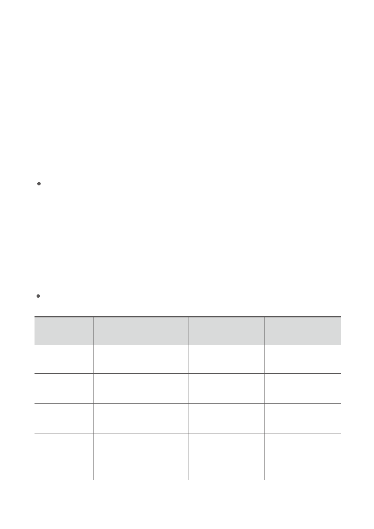
Left nger wheel:for the control of the gimbal pitch.
Right nger wheel:for the control of gimbal yaw.
Left top button:The gimbal back to position by short pressing the key; press the key until there is
a vibration, and the gimbal faces downward; short press the key for 2 times, sele mode is
triggered.
Right top button: Short press the key to take a photo; when it is not shooting video, press the
key until there is a vibration, and camera shooting starts; during video shooting, press the key
until there is a vibration, and video shooting stops.
Flight mode switcher: P/N/E; P: Professional (manual); N: standard (Normal); E: Easy Control (the
direction away from the remote controller is the front of the aircraft).
Indicator for standard remote controller
SStandard remote controller has a three-color battery level indicator. The indicator shows the
battery level of the battery when the remote controller is on (whether charging or not):
In case of charging when the remote controller is o, the indicator is red, indicating charging;
when the remote controller is fully charged, the indicator is green, indicating full charging; in
case of emergency alarm during ight, the battery level indicator ashes four times each second
in the current color.
Alarm
Type of Alarm
Prompt
Aircraft takeo/
landing prompt
Aircraft return-
to-home prompt
Button Backlight
The backlight of takeo/
landing key is normally on
The backlight of return-to
-home key is normally on
Color of Three-Color
Light
No action
No action
The red light is
Buzzer
No action
Dripping sound, 1 cycle
for buzz per second
Dripping sound, 4 cycles
Low power alarm No action
normally on
for buzz per second
Not positioned
by GPS
No action
1 cycle per second in
the color of current
battery level
No action
27
Page 32
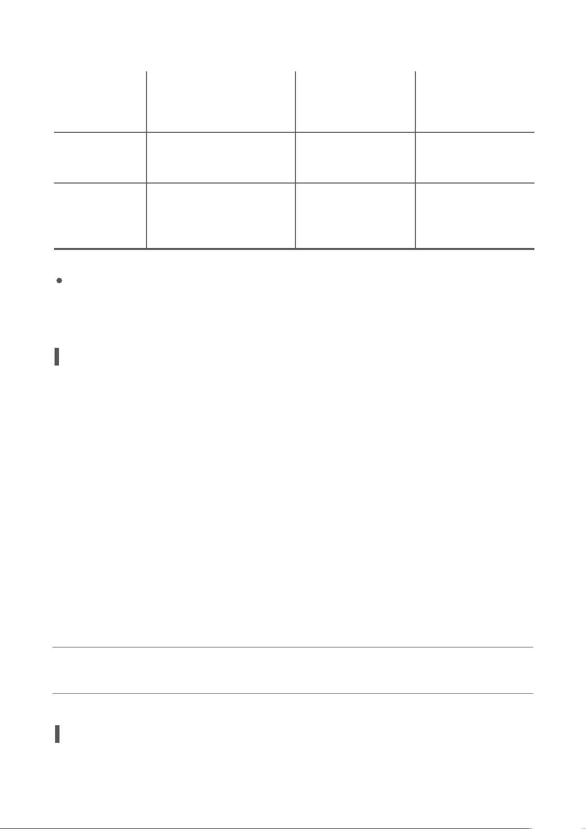
The aircraft not
connected
Cyclic switching of
No action No action
red, green and blue,
3 cycles per second
Change of GPS
positioning state
State change of
connection with
the aircraft
Compliance version of standard remote controller
PowerEgg remote controller complies with both CE standards and FCC standards.
No action
Inaction
No action
Inaction
Tick
Connected, Do-Re-
Mi-Fa disconnection,
Fa-Mi-Re-Do
Overview of Gesture-based Remote Controller
PowerEgg gesture-based remote controller can control the altitude, forward, backward, left and
right ight of the aircraft; the gesture-based remote controller integrates one-click takeo/landing,
one-click return-to-home, one-click following/one-click sele, control of 3-axis gimbal pitch, taking
photos and video shooting. Users can easily complete various operations of the aircraft with the
assistance of the remote controller.
The built-in rechargeable battery in PowerEgg gesture-based remote controller has a capacity of
1,500mAh and can continuously work for 10 hours. The current battery level may be checked via
the battery level indicator.
The standard remote controller has a built-in GPS receiver, which is available only when the GPS
signal of the aircraft and the remote controller is good. The gesture-based remote controller and
the aircraft are unavailable where the GPS signal is poor or there is no GPS signal (such as indoor,
urban agglomeration and accessory of high structures).
Compliance version: PowerEgg remote controller complies with both CE standards and FCC
standards.
Operation of Gesture-based Remote Controller
28
Page 33
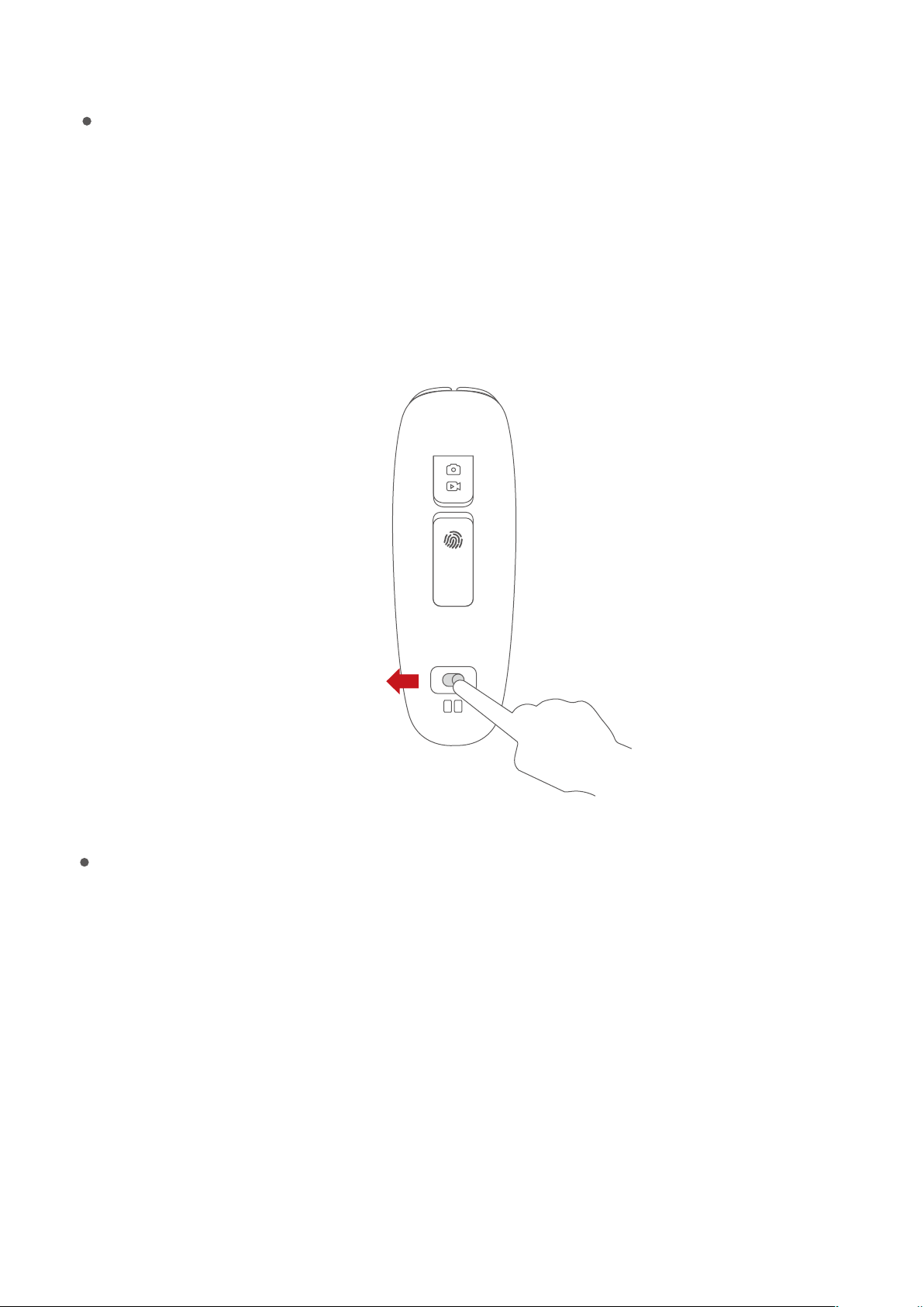
Start-up and shutdown of gesture-based remote controller
The remote controller may be started by sliding the power switch from the left to the right. The
connection status of the remote controller may be distinguished according to the notication tone
of the remote controller. When the remote controller plays music for 1 second, it indicates that the
communication connection between the remote controller and the aircraft is successful. Slide the
power switch from right to left to shut down the remote controller.
on off
Switch on the power switch
Charging of gesture-based remote controller
1.Connect the charger to an AC power source (100-240V, 50/60HZ; use a power converter if neces-
sary);
2.Connect the battery and the charger when the battery is on or o;
3.During charging, when the standard remote controller is shut down, the battery level indicator will
turn red and then turn green when it is fully charged;
4.During charging, when the standard remote controller is on, the battery level indicator will show
the battery level of the lithium battery:
29
Page 34
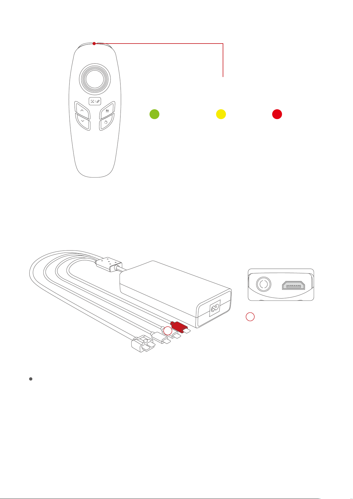
Battery level indicator
Less than 10%10%-30%More than 30%
The battery of gesture-based remote controller should be charged with the special charger ocial-
ly designated by PowerVision, which will not be liable for any consequences caused by charging
the battery with the charger not ocially provided by PowerVision.
Gesture-based
3
3
The battery will be fully charged in 2h.
Control of gesture-based remote controller
Start of motor: short press takeo key and then keep pressing landing key (complete within 1
second). Then the screw propeller is unlocked and started.
Emergency locking: In case of emergency, press the combination key, i.e. 3-axis gimbal pitch,
ascend/descend + taking photos and camera shooting locking propeller, for 2 seconds for emer-
gency shutdown. Such propeller stop mode may be used in case of emergency. Under normal
Remote Controller
30
Page 35
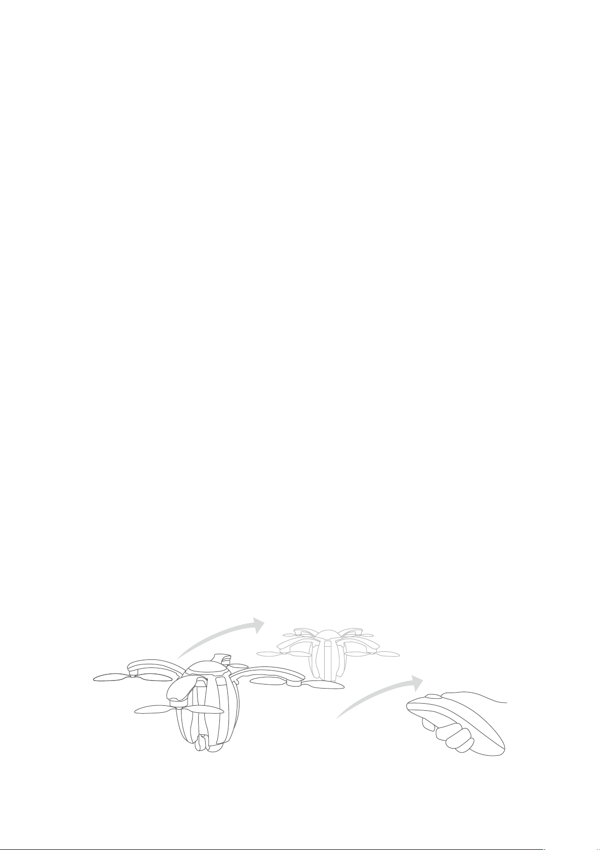
circumstances, the motor may be automatically stopped when the aircraft lands.
One-click takeo/landing button: When the aircraft has not taken o, press and hold the key until
there is a vibration, and the aircraft begins to take o; when the aircraft takes o, press the key again
until there is another vibration, and the aircraft begins to land; short press the key in the process of
landing, and the aircraft stops landing.
One-click return-to-home: When the aircraft is not in return-to-home mode, press the key until there
is a vibration, and the aircraft begins to return-to-home; when the aircraft is in return-to-home mode,
short press the key until there is another vibration, and the aircraft stops return-to-home.
Ascend button:control the upward ight of the aircraft.
Descend button: control the downward ight of the aircraft.
Middle button:short press the button for sele; keep pressing the key until there is a vibration for the
function of following.
Taking Photo/Video shooting button: short press the button for photographing; keep pressing the
key until there is a vibration for videoshooting if it is not in video shooting state and for stopping
video shooting if it is in camera shooting state.
Joystick:Joystick up and down control 3-axis gimbal pitch; joystick left and right control left-handed
rotation/right-handed rotation of the 3-axis gimbal.
Forward and backward/left and right of gesture-based aircraft:Press the gesture activation button,
with remote controller positioned pointing straight up, the remote controller can control the forward
and backward ight of the aircraft with the bottom as the center point by leaning it forward/back-
ward; the remote controller can control the left and right ight of the aircraft with the bottom as the
center point by leaning left/right; when the key is released, the aircraft will hover.
*Gesture-based remote controller is not available to indoor ight, for which standard remote cont-
roller shall be used.
Using the gesture-based control
31
Page 36

Indicator for gesture-based remote controller
The gesture-based remote controller has a three-color battery level indicator. The indicator shows the
battery level of the battery when the remote controller is on (whether charging or not):
In case of charging when the remote controller is o, the indicator is red, indicating charging; when
the remote controller is fully charged, the indicator is green, indicating full charging; in case of
emergency alarm during ight, the battery level indicator ashes four times each second in the
current color.
Alarm
Type of Alarm
Button Backlight
Prompt
Aircraft takeo/
landing prompt
Aircraft return-
to-home prompt
The backlight of takeo/la-
nding button is normally on.
The backlight of return-to
-home key is normally on
Low power alarm No action
Not positioned
by GPS
No action
The aircraft not
No action No action
connected
Color of Three-Color
Light
No action
No action
The red light is
normally on
1 cycle per second in
the color of current
battery level
Cyclic switching of
red, green and blue,
3 cycles per second
Buzzer
No action
Dripping sound, 1 cycle
for buzz per second
Dripping sound, 4 cycles
for buzz per second
No action
Change of GPS
positioning state
State change of
connection with
the aircraft
No action
Inaction
No action
Inaction
Tick
Connected, Do-Re-
Mi-Fa disconnection,
Fa-Mi-Re-Do
32
Page 37
Base station
Overview of Base station
This section describes PowerEgg base station, including its usage and precautions. The working
frequency band of PowerEgg base station is 2.4Ghz. The base station integrates advanced 4K/HD
image transmission system, can directly output HD aerial image to mobile device, and can support
mobile phones, tablet computers, and other mobile smart devices with dierent specications.
Operation of Base station
Start-up and shutdown
Press the power switch key for 3 seconds until the indicator near the power key turns on; when it is
necessary shut down the base station after use, press the power switch key for 3 seconds again
until all indicators are o.
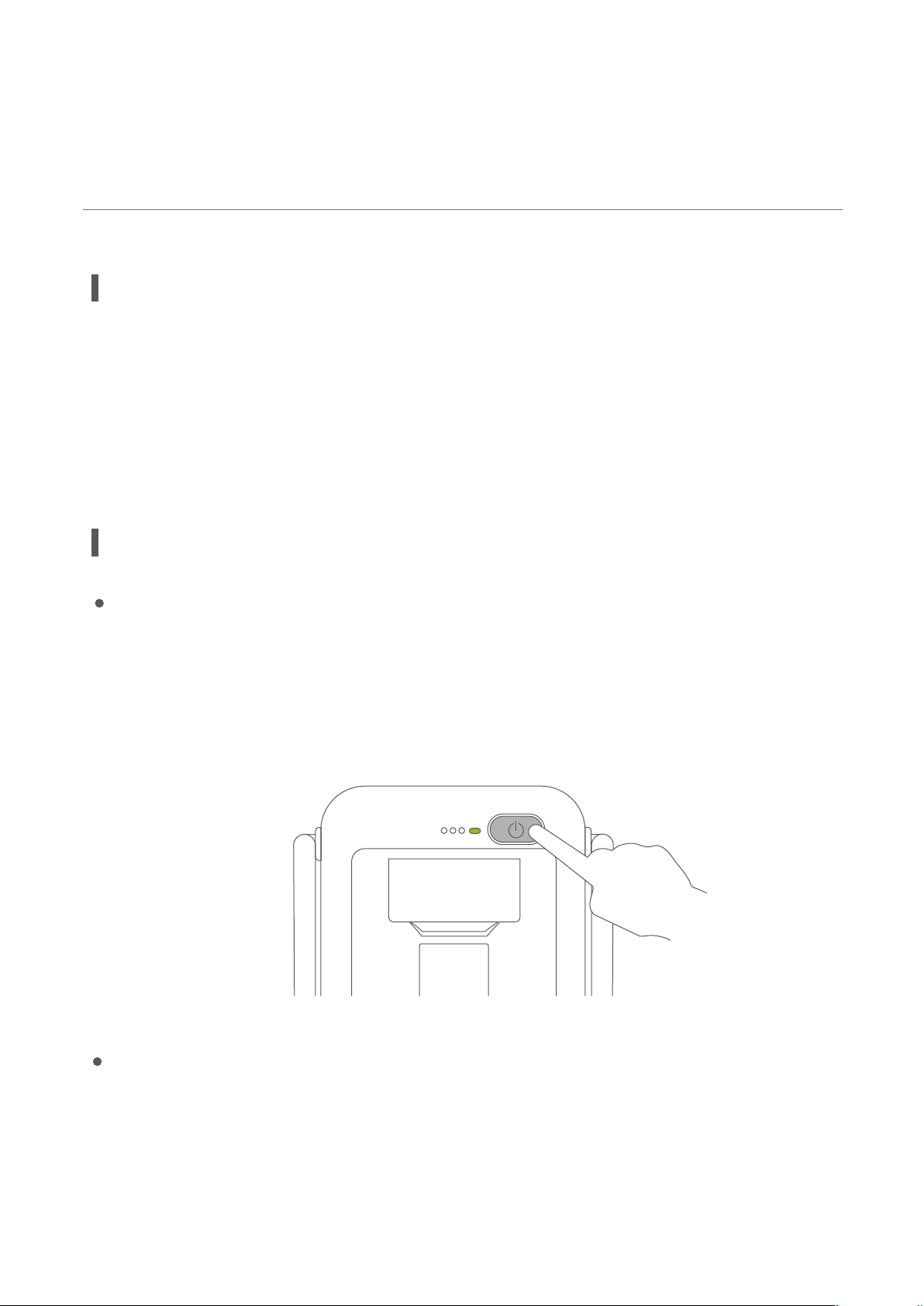
Connection of wireless base station
For the connection of wireless base station, power on the aircraft and the wireless base station; wait
for about 35 seconds, when the 3 Led lights beside the power key are constantly on, the wireless
base station is successfully connected to the aircraft. See the gure below:
33
Page 38
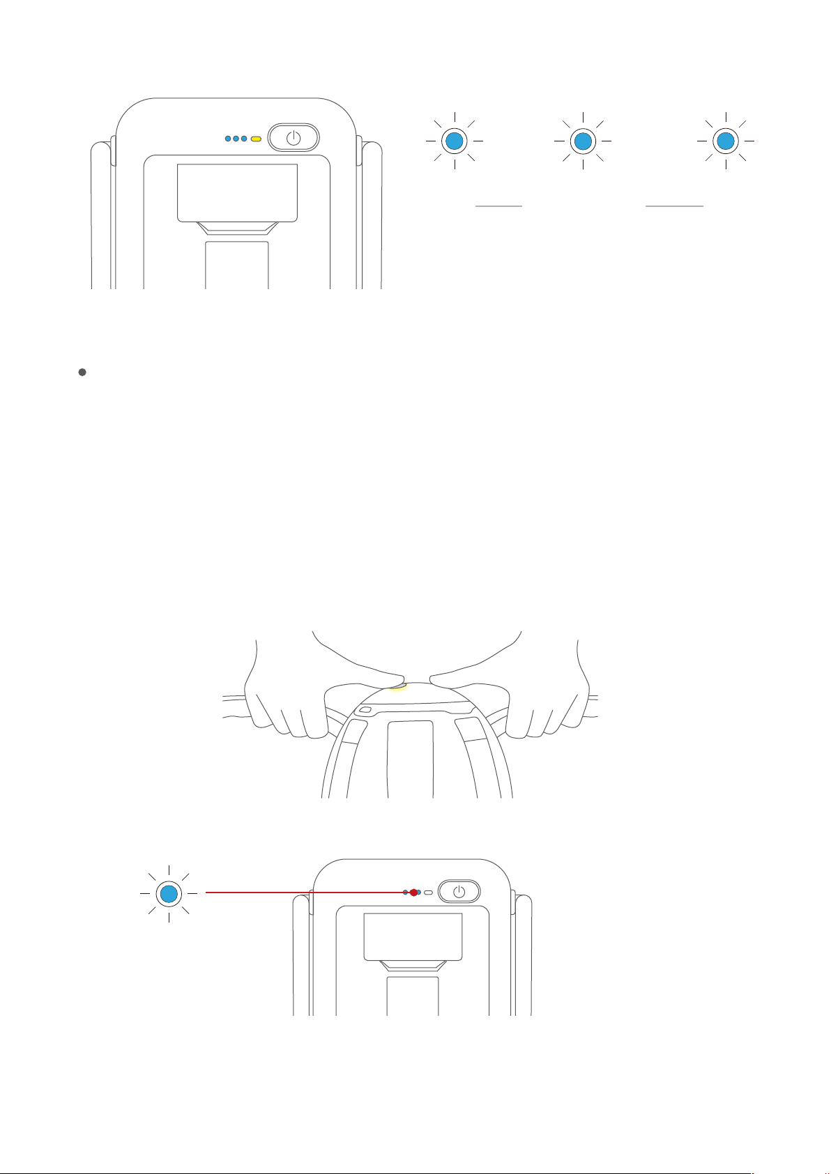
Low HighWireless signal
The number of LED lights indicates the strength
of the wireless signal connection.
Frequency adjustment of base station
Steps:
1. Switch on the aircraft and the base station, and wait for the initialization of the aircraft.
2. Use Vision+ to connect to base station.
3. Press the power key of the aircraft for 10s until the tail status indicator in blue ashes slowly; 3
seconds later, press the power key for 10s until the tail status indicator in blue changes from slow
ash to constant light. It enters into frequency adjustment function.
Blue light ashes slowly
34
Page 39
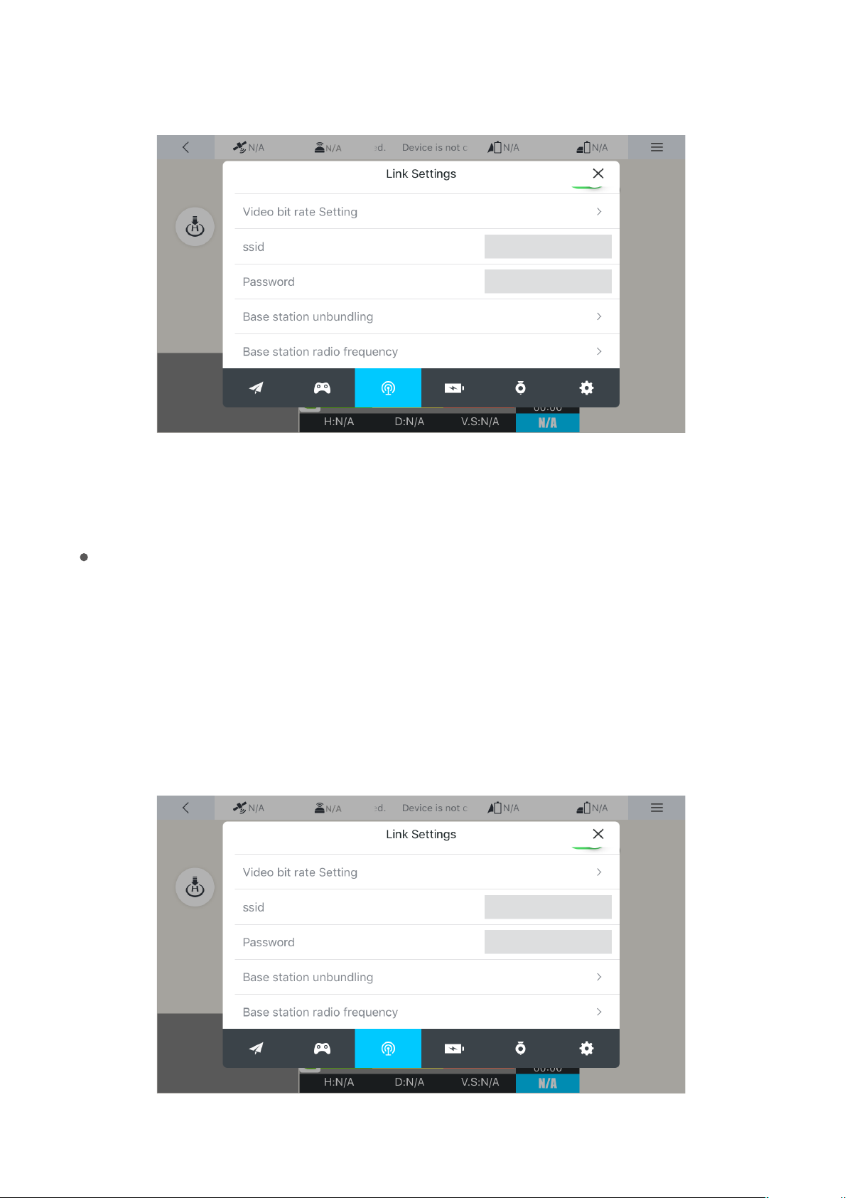
4. Press frequency adjustment key in Vision+ as shown in the following gure:
5. When the operation is successful, Vision+ will prompt that frequency adjustment is
successfully completed.
Unbinding
Steps:
1.Switch on the power of aircraft and the power of the base station, and wait the connection
between the aircraft and the base station.
2.Use Vision+ to connect to base station.
3.Click the “Unbinding key” of Vision+ to unbind the aircraft and the base station. When the
blue LED light of the base station is in water light state, the module is successfully unbound.
35
Page 40
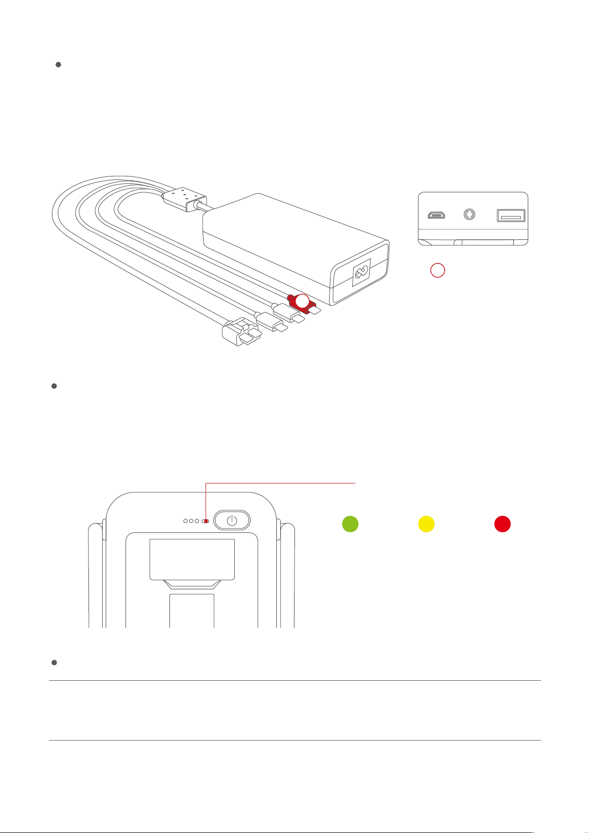
Charging of base station
The base station should be charged with the special charger supplied by PowerEgg for 5h.
The red Micro USB port should be used for charging.
4
Base Station
4
Indicator of base station
The built-in rechargeable battery of the wireless base station has a capacity of 6,000mAh. The
current battery level may be checked via the battery level indicator.
Battery level indicator
The module will be fully
charged in 5h.
Less than 20%20%-60%More than 60%
Compliance version of remote controller
Compliance version: PowerEgg wireless base station complies with both CE standards and
FCC standards
36
Page 41
4K UHD Gimbal Camera
Overview of 4K UHD Gimbal Camera
This section describes the technical parameters of the camera, and the range of motion and work
mode of 4K UHD gimbal camera. Three-axis stabilized gimbal helps the camera isolate the gesture
and high-frequency vibration of the aircraft. The control accuracy is up to 0.05° to help the camera
take stable and smooth pictures and conduct video shooting. Users can adjust the pitch and
heading angle via the nger wheel.
3-axis gimbal use
Modes
Following mode: the rotation direction of the 3-axis gimbal follows the heading of the aircraft. The
pitch and heading are controllable, but rolling is not.
FPV mode
The motion of the 3-axis gimbal in rolling direction follows the motion of the aircraft in rolling direc-
tion. Thus users can obtain the experience of the best ight angle of view.
Precautions:
1.Please open the four arms and bottom cap of the aircraft before switching it on.
2.Please deploy the aircraft landing gear before the landing of the aircraft to avoid impacting the
3-axis gimbal and Camera.
3.Please place the aircraft on at open ground before taking o and do not impact the gimbal or
camera assembly after switching on.
37
Page 42
Introduction to Vision+
Overview of Vision+
PV ground control system is the UAV software of PowerEgg. Users can obtain the status
information of PowerEgg and can control UAV, 3-axis gimbal and camera module via Vision+.
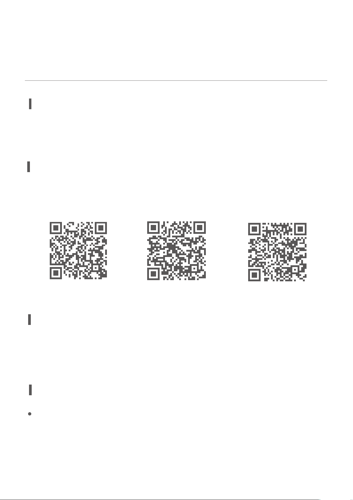
Download APP and other resuoces
Please scan QD code to download Vision + APP, PC Suite, User Manual, Specication and watch
video tutorials.
中国区 Europe North America
Product Description
To be used for real-time transmission from the camera, gimbal adjustments, setting of waypoints,
ight modes, electronic fencing and return-to-home points, and ight logs and the storage of
pictures and movies taken, etc.
Introduction to Vision+ Functions
Homepage
Start Vision+. The interface displays the smart ight page by default; the navigation bar at the
bottom displays smart ight, photo album, service and my entrances successively.
38
Page 43
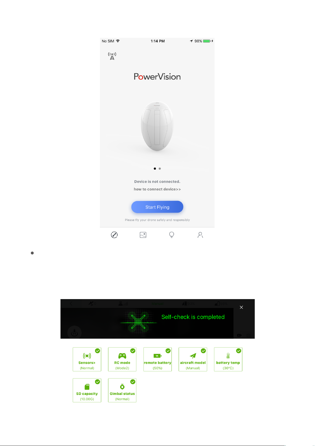
Systems-Check of the aircraft
When the equipment is connected, click the “Start Flying”. A systems check will commence. Flying
is only possible after the aircraft passes the systems-check. If something fails the systems-check, it
39
Page 44
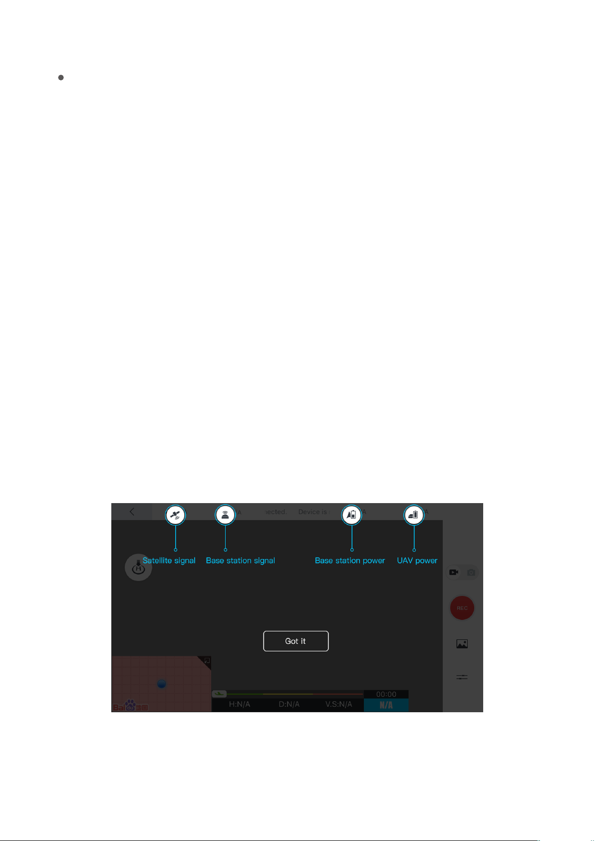
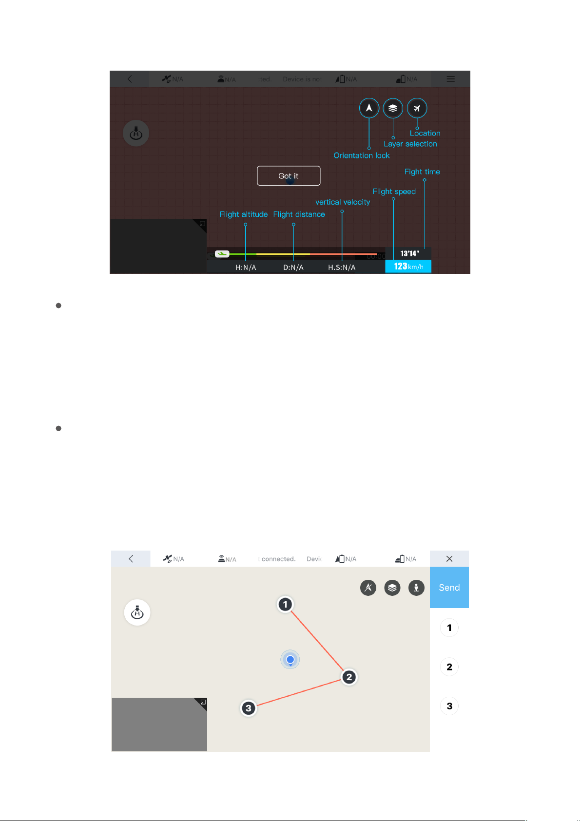
Display of relevant parameters
Aircraft altitude: it displays N/A if there is no value, and displays the current altitude of the aircraft
if there is a value.
Man-machine distance: the distance between the aircraft and the operator.
Vertical velocity: velocity of vertical rise and fall of the aircraft.
Horizontal velocity:the ight velocity of the aircraft at current level.
Flight duration:ight duration for aircraft.
Satellite signal:the number of satellite signals received by the GPS of the aircraft. The aircraft can
guide the ight route and trail via satellite signal. Twenty is the maximum number of possible
signals received by the GPS of the aircraft.
Base station signal:the strength of signal will impact the eciency of the aircraft and base station
to receive and send information.
Equipment connection status: display of information on connection status of the equipment.
Battery level of the aircraft: it displays N/A if there is no value and displays a percentage (100%) if
there is a value.
Battery level of the base station: it displays N/A if there is no value and displays a percentage
(100%) if there is a value.
Smart ight menu:waypoint planning, ight mode, return-to-home point setting and safe mode
setting.
40
Page 45
One-click return-to-home
One-click return-to-home: the aircraft return-to-homes automatically; if “return-to-home point
setting” is set, it return-to-homes to the user assigned location; if “return-to-home point setting” is
not set, it return-to-homes to the takeo point. See the “Smart return-to-home” section for details.
Route planning
Click “waypoint planning” to select the planned points on the map and plan a route by point
selection on the map and automatic connection. The velocity, height, hovering duration and
other parameters of each waypoint may be set. Upon the completion of planning, click Start, and
then the aircraft will automatically execute the ight mission.
41
Page 46
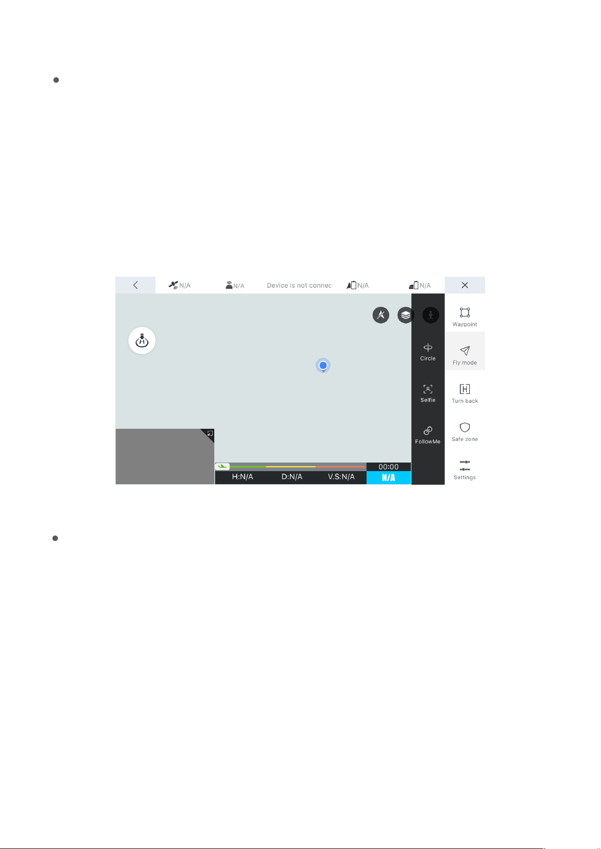
Flight Mode
Flight modes include circling mode, sele mode and follow mode.
Orbit mode:The aircraft will orbit a point set by the user in the Vision+ software.
Following mode: when the following mode is started, the aircraft will follow the position of the
remote controller at certain distance. Please conrm that the remote controller is started and GPS
is normal.
Sele mode: when sele mode is started, the aircraft turns about to face the position of the remote
controller.
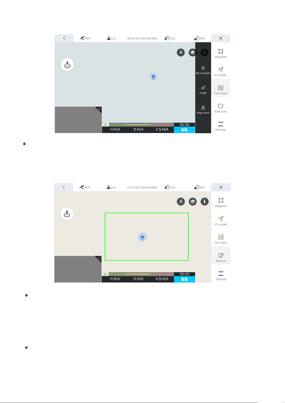
Return-to-home point setting
Return-to-home point setting includes: current position, aircraft starting point (default value) and
point selection on the map.
User position: the aircraft automatically return-to-homes to the current position of the remote control-
ler.
Take-o point of the aircraft:the aircraft automatically return-to-homes to the position of the remote
controller.
Location selected on the map: click the map to switch the position of return-to-home point.
42
Page 47
Electronic fence
Click “safe zone” to select a safe zone on the map. The aircraft will y within the safe fence in the selected
zone. When the aircraft ies outside the electronic fence, it will return-to-home and may stop
return-to-home when it enters the electronic fence and keep ying in the original mode.
Positioning
Positioning: human positioning and aircraft positioning .
Not connected to the aircraft: only human positioning is available.
Connected to the aircraft: both the man and the aircraft are positioned.
Map layer switching
Map mode switching: standard map and satellite map.
43
Page 48
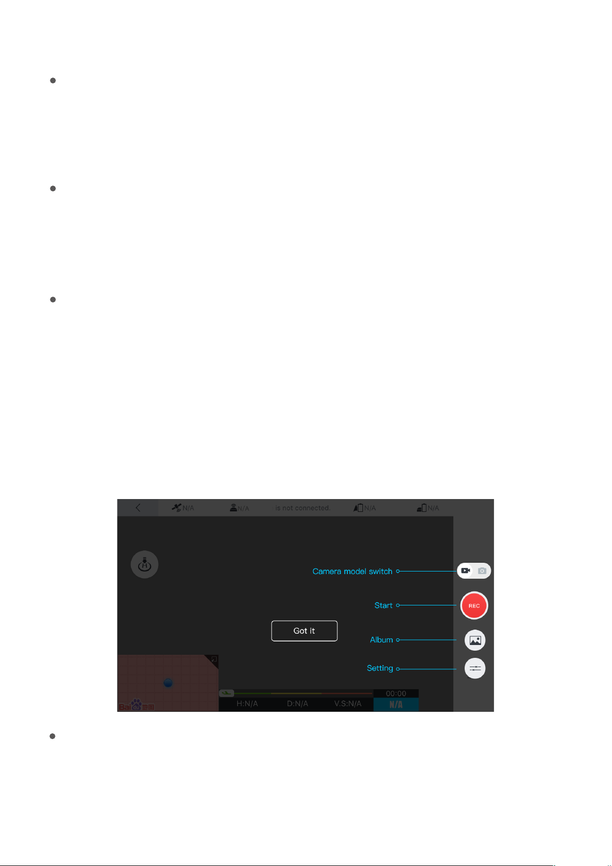
Locking of map orientation
Locking of map orientation: the map orientation is locked by default.
Map locked: the map orientation will not change by rotating the phone left and right.
Map unlocked: the map orientation will change by rotating the phone left and right.
Back transmission of images
The UAV has a camera image transmission device, which transmits images via RF, data transfer radio or
satellite to the base station. The UAV will transmit the real-time pictures to Vision+ and the users can
view the ying scene of UAV through Vision+.
Taking photos and Video Shooting
Shooting module contains: video shooting, image shooting, photo album and camera parameter
settings.
Video shooting:control the camera to shoot a video.
Image shooting:control the camera to shoot an image.
Photo album:to cache the videos and images shot by the aircraft in the process of ight (HD original
images are stored in SD card of the camera).
Setting of camera parameters:set the resolution, focus mode, ip and other parameters of the camera.
Setting
Users can congure the ight, remote controller, image transmission, battery, 3-axis gimbal and other
options on the map to meet the individual demands of users.
44
Page 49
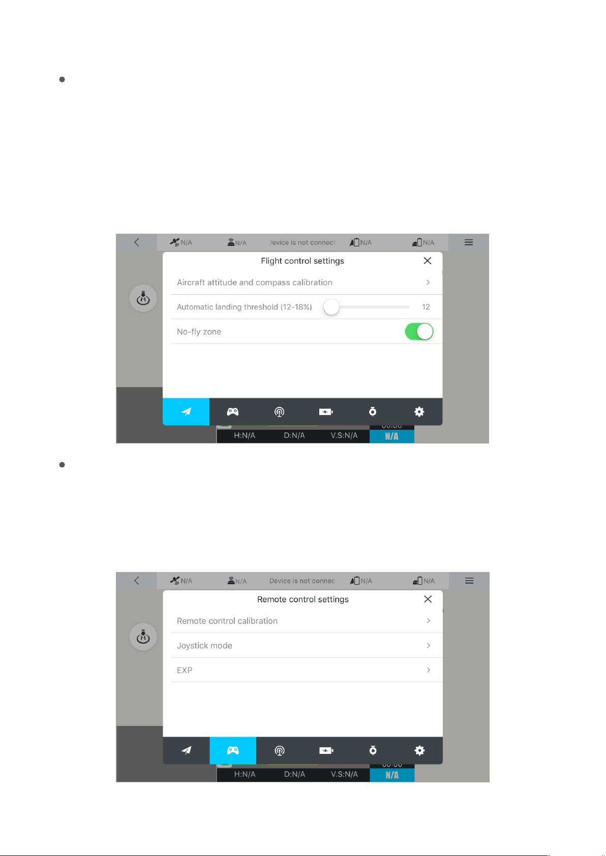
Flight control setting
Aircraft attitude and compass calibration:when the magnetometer of the aircraft is abnormal,
magnetic calibration should be performed manually according to the prompt.
Aircraft landing threshold:users may self-dene a minimum battery level for forced landing of the
aircraft.
No-y zone restriction:when no-y zone restriction is switched on, the aircraft cannot y in the
zone in an unlocked manner.
Remote controller setting
Remote controller calibration: when the remote controller requires calibration, the function may
be used to calibrate the remote controller.
Joystick mode: users can select appropriate joystick mode according to their own needs.
EXP: users can self-dene EXP according to their own habits.
45
Page 50
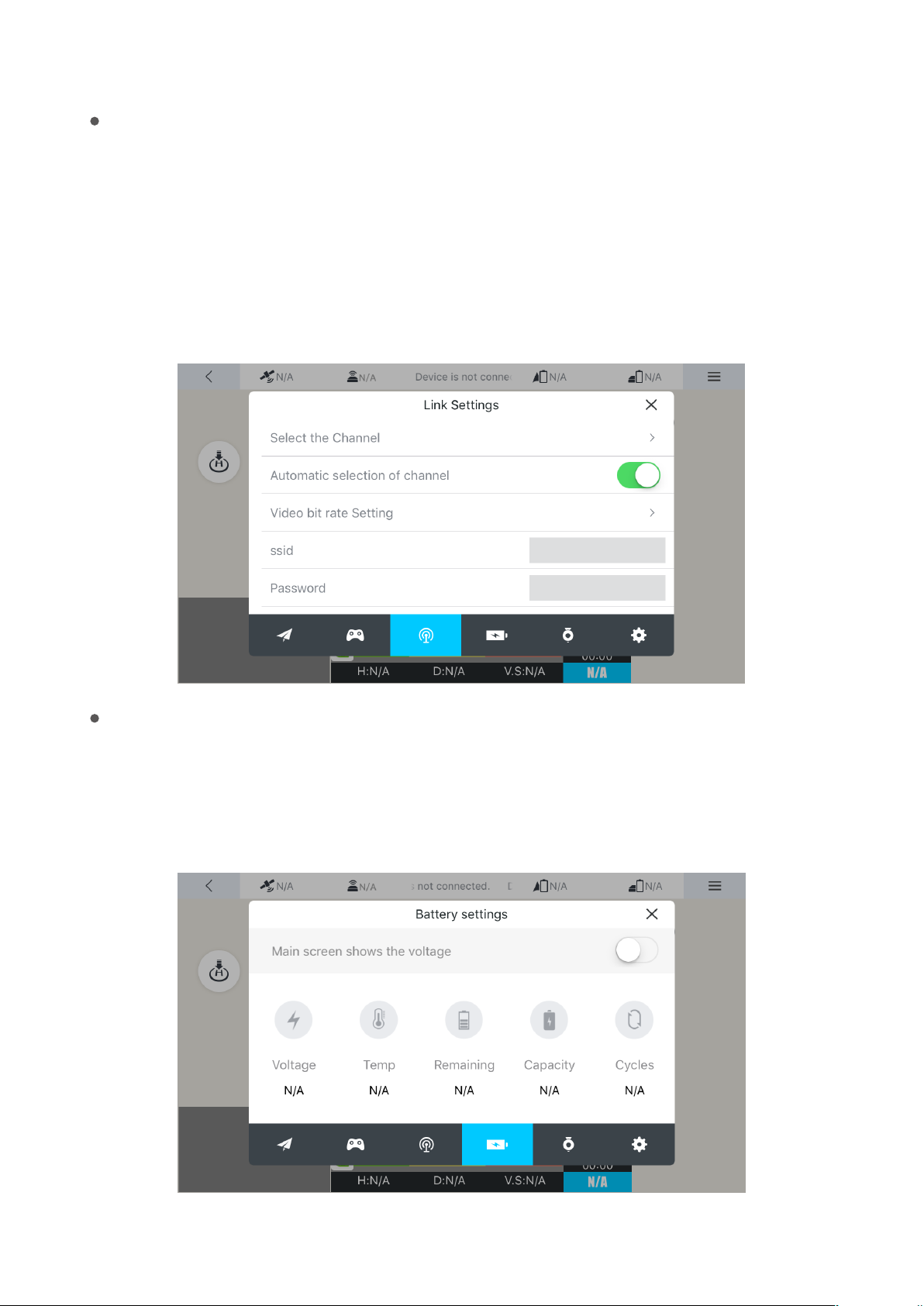
Link setting
Channel selection: users can select a self-dened channel according to the interference condi-
tions to realize the optimum ight experience.
Automatic setting of the channel: when started, it will automatically select the channel for you
without manual setting.
Video code rate setting: users can set the code rate for image transmission according to their own
needs.
Battery setting
Voltage display on the main screen: when the switch is switched on, the main screen will
display both the current percentage of remaining battery level and voltage. In addition,
some details of the aircraft battery can be found here.
46
Page 51

Media Library
It is used to manage photos and videos taken by the aircraft. Here you can upload, down -
load, share, edit and delete pictures and videos.
Service
The Service module includes four sub-modules: Flight Academy, Flight Peripherals, Technical
Support, and Repair Application. If you click to enter the corresponding module, it will
directly skip to the secondary function page.
Flight Academy
Flight Academy allows you to view the videos, messages and other information.
Flight Peripherals
Flight Peripherals allow you to view ight messages. Each message page allows third-party sharing
and clicking likes.
Technical Support
Technical Support is to answer the questions about the UAV, and provide telephone, e-mail and
related services.
Repair Application
Repair Application is used for the application for after-sales repair services for the UAV.
47
Page 52
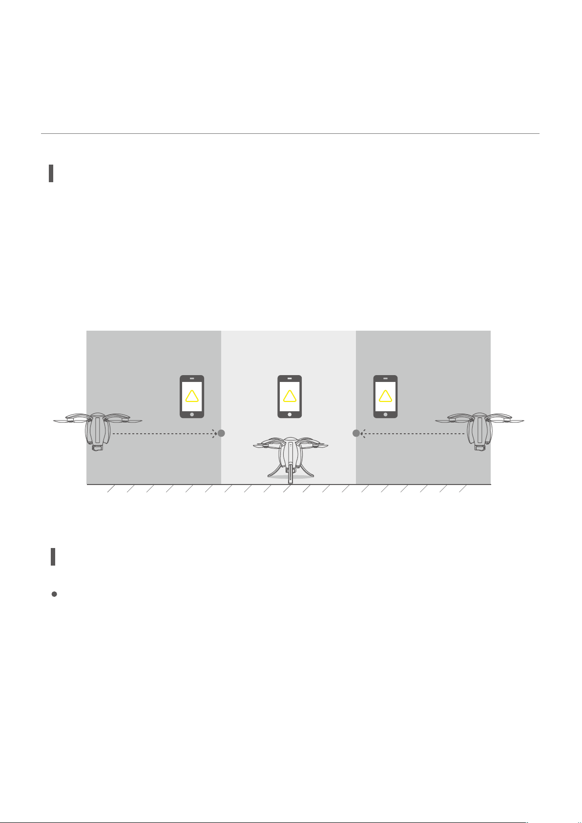
Flight
Flight Restrictions and Special Restricted Areas
In view of the management system for UAV and airspace control of each country’s civil aviation
authority, the UAV should not y in certain specic airspaces to ensure safety. Vision + will prompt
the user when the aircraft enters these restricted areas from unrestricted areas, and the user can
choose whether to continue the ight. When the aircraft is released to y from the restricted area,
Vision + will prompt the user to choose whether to continue locking and start to y.
Non-no-y zone Non-no-y zoneNo-y zone
!
*See the laws of each country for no-y zones.
!
!
Safe Flight Conditions and Precautions
Flight environment requirements
1.Do not y in harsh weather, such as windy (wind speed ≥ Scale 5), snowy and rainy weather.
2.Beginners are suggested to choose open space for ight; avoid high-voltage cables, towers, com-
munication base stations or transmitting towers and other strong interference facilities, so as not to
aect the eective reception of GPS signals and eective communication of remote controller.
3.Please note that ight performance will be aected at high altitude (above 5,000 m above sea level)
due to environmental factors resulting in performance degradation of the battery and power system
48
Page 53
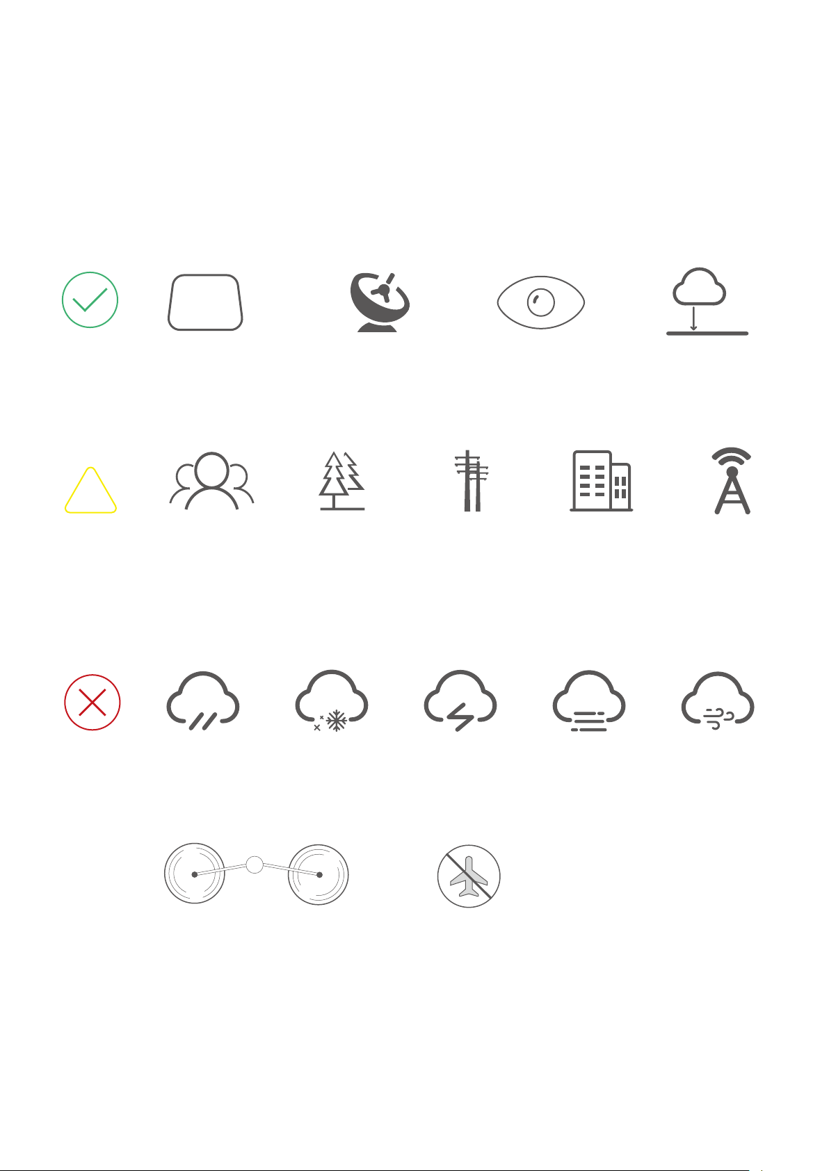
of the aircraft.
4.GPS mode cannot be used in Antarctic Circle or Arctic Circle, where attitude mode and visual posi-
tioning system can be used.
Fly in an open and
unobstructed space
+ + +
Keep your
GPS Signal>13 Satellites
drone in sight
Flying below
<120m
120m
!
Keep away from crowds, trees, electric wires, tall buildings, airports and signal launching
towers. Radio towers, high-voltage wires, substations, and large magnetic metal struc-
tures may interfere with its remote controller signals and compasses, threatening ight
safety.
Do not y in severe weather conditions involving rain, smog, snow, tornados and
strong wind (speed above 10m/s).
No-y zone
Do not touch the spinning pro -
peller, or it may cause serious
personal and property damages.
Please refer to following website:
http://knowbeforeyouy.org/air-space-map/
49
Page 54
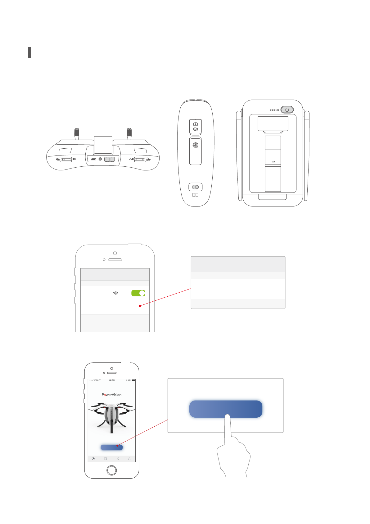
Connect the Aircraft, Remote Controller and Vision+
Enter Password
Password 1234567890
Start Flying
Device is connedted
1.Start the standard remote controller / gesture-based remote controller and the base station.
or
on off
+
2.Turn on your phone and connect WIFI: Power _ Groundxxx with the password: 1234567890.
WIFI
WIFI
Power_Groundxxx
√
3.Start Vision +. After about 30 seconds, click Start Flying when it shows device is connected.
Device is connedted
Start Flying
50
Page 55
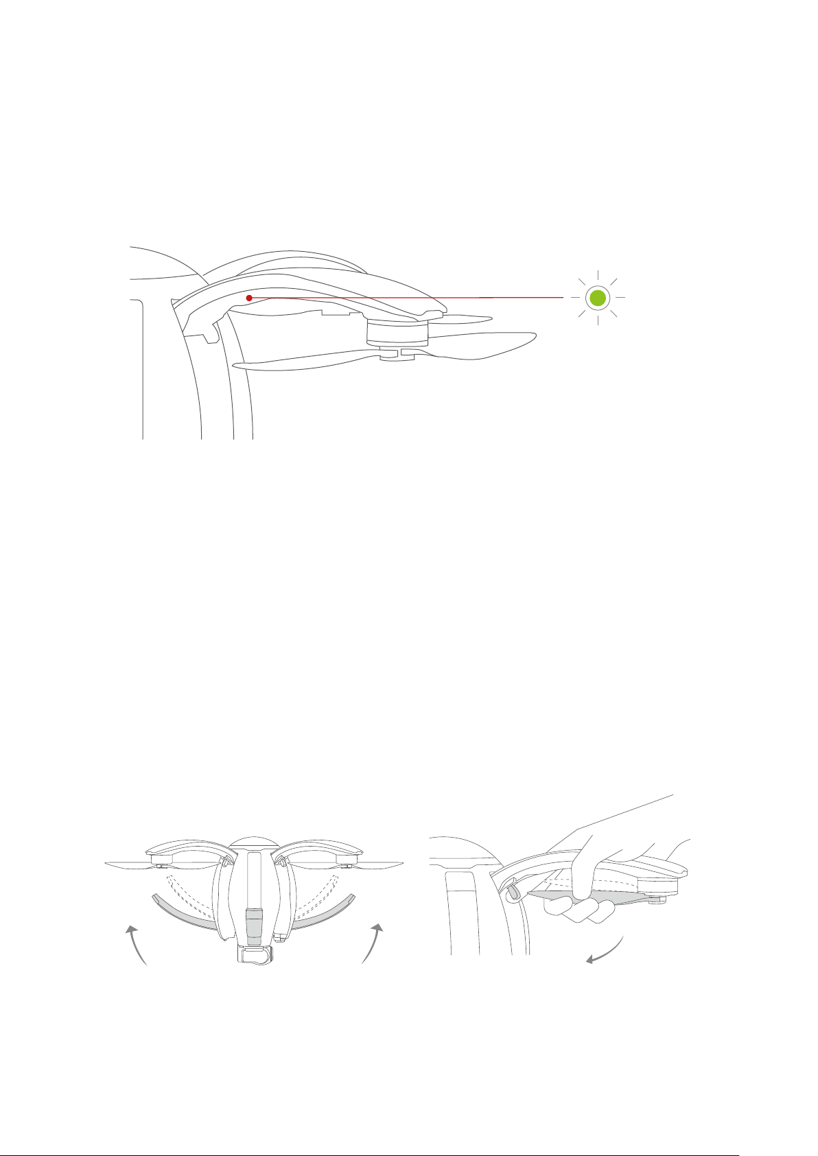
4.For outdoor ight under the mode of P/N/E, wait until aircraft status indicator becomes green, and
the status indicator of standard controller or Maestro
™ turns green. This indicates the aircraft is
prepared for unlocking and ight.
*The Wi-Fi communication frequency of the base station is 5G. Devices not supporting 5G Wi-Fi cannot be connect-
ed to the base station. Wi-Fi password can be modied or reset.
**To y the UAV at unfamiliar locations, please connect the Internet before connecting the base station, and open the
APP to zoom in the map to save the data to local cache, so as not to aect the normal display of the map during ight.
5.Press the power button three times in rapid succession, and the landing gear automatically
closes. After the propellers are retracted, repeat the process in reverse order to retract the arm. It
should be noted that the index nger needs to pull the unlock switch outward, and then follow
the momentum to close the arm downward.
51
Page 56
Compass Calibration
Precautions
The compass must sometimes be calibrated before ight. As the compass is susceptible to the
complex environment outside, when calibrating the compass, attention should be paid to the
following matters in order to ensure the accuracy of the compass. This is to ensure an ideal condi-
tion of the aircraft.
1.The calibration site should be open, and away from strong magnetic elds, such as magnetic
mines, parking lots, or construction areas with underground steel.
2.Do not carry magnetic items, such as mobile phones and keys.
3.Do not calibrate the compass indoors.
Compass calibration procedures
1.Open Vision + App. After ensuring the device is connected, enter the “Start to y” interface, and
then click “Setup” in the lower right corner of the menu bar. Then select “Flight Attitude and
Compass Calibration” in the ight setup list. Click “Calibration” to enter the “Compass Calibration”
interface, and the compass calibration program starts.
2.There are six setting positions in the interface, as shown in the gure. Calibration sequence of
the three positions is not limited. First, keep it in one position. When the image of the correspond-
ing position of the aircraft becomes yellow, it indicates that the direction has been identied.
Then rotate the aircraft around the vertical axis of the current position. When the color of the
image turns green, it indicates that the calibration of this direction is completed. Then calibrate
the other positions in the same way:
52
Page 57
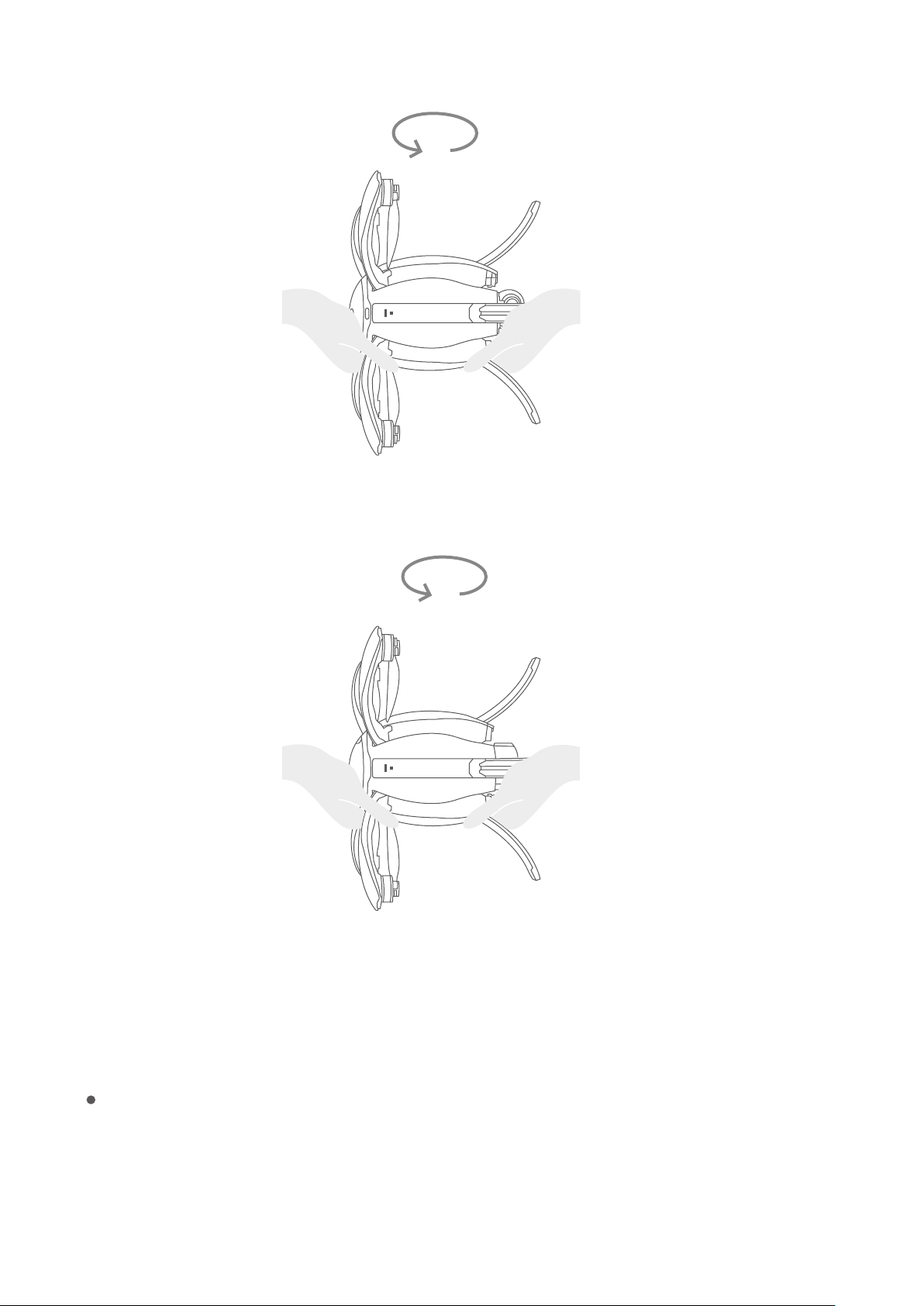
Power button facing forward
Power button facing upward
3.When the three setting positions in the interface are all green, the calibration is complete.
Conditions requiring recalibration
1.The ight site is far from the site of last calibration;
2.It spins in ight or cannot y in a straight line.
53
Page 58
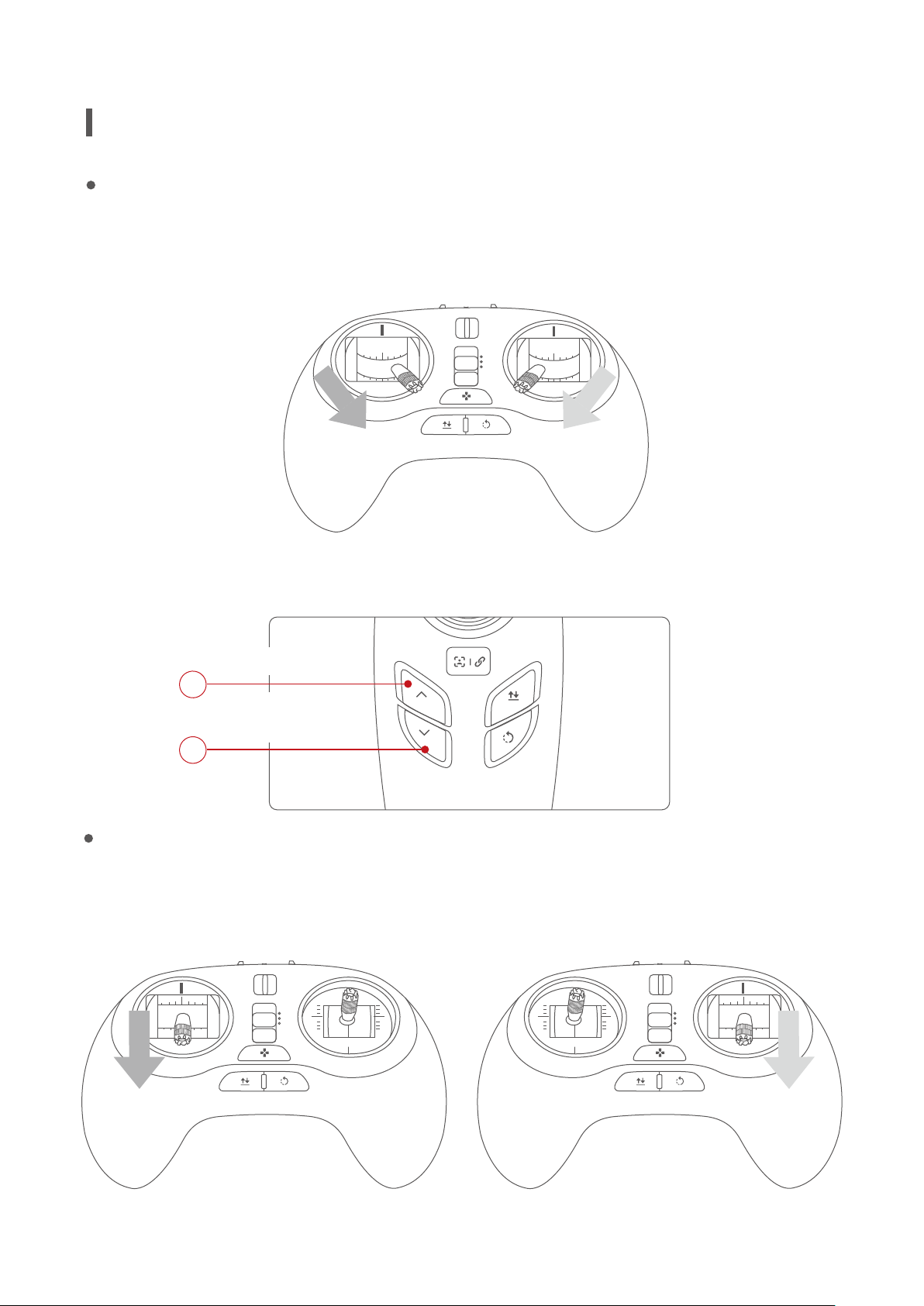
Start-up/Shutdown of the Motor
Start the motor
Connect the remote controller, and pull the sticks down and in to start the motor.
For the standard remote controller , pull both joysticks inward and downward to start the
motor. After the motor is started, release the joysticks quickly.
P
N
E
For the gesture-based remote controller , press the Ascend key, then press and hold the
Descend key to start the motor. After the motor is started, release the key quickly.
Press the Up key
1
Press and hold the
Down key
2
Shut down the motor
Under normal circumstances, after the aircraft lands on the ground, the user will pull the
Ascend/Descend joystick back to the middle or down to the bottom. The aircraft motors will
shut down and automatically lock on the ground.
P
N
E
or
P
N
E
Mode 2 Mode 1
54
Page 59
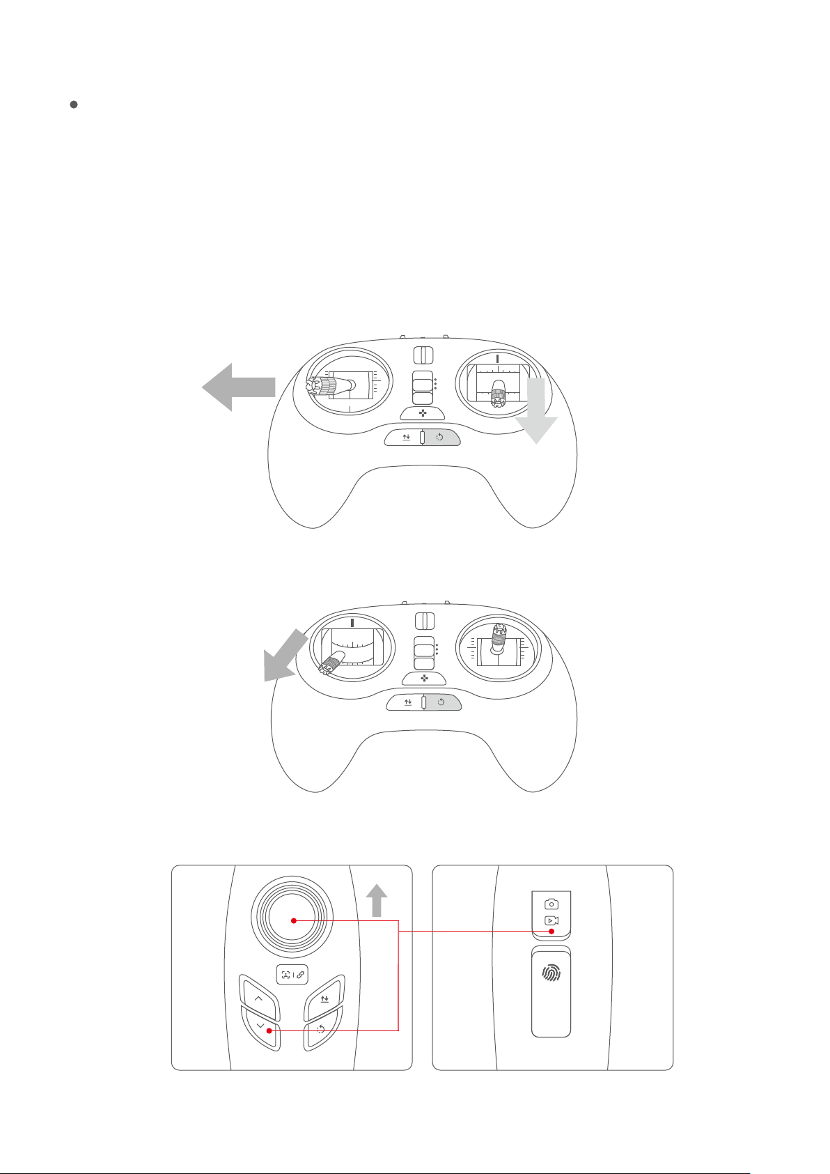
In-air motor shutdown method
The in-air motor shutdown method can only be used to shut the motor down in case of special
conditions (such as when an aircraft is crashing into a crowd) where emergency shutdown is
needed to minimize personnel injury. Note: The aircraft will fall to the ground and most likely
be destroyed.
Perform the following joystick action to shut the motor down:
Standard remote controller (Mode 1): Pull the Ascend/Descend joystick to the bottom, the yaw
joystick to the left, and press and hold the return-to-home button till the remote controller
vibrates.
P
N
E
Standard remote controller (Mode 2): Pull the ascend/descend joystick to the lower left corn-
er, and press and hold the return-to-home button till the remote controller vibrates.
P
N
E
Gesture-based remote controller: Hold down the Descend button+ Camera button and push
the joystick to the top till the remote controller vibrates.
55
Page 60

Basic Flight
1.Take out the aircraft, the battery, the base and the remote controller/ base station from the pack-
age, and place the aircraft on the base.
2.Release the buckles at the end of the arms to open the four arms in turn.
3.Open the aircraft’s top cover to place the battery into the body and fasten the cover.
4.Remove the lower cover (otherwise, it will damage the 3-axis gimbal when it is powered on and
initialized).
5.Press once quickly, then again and hold down the power button to power on the aircraft. Wait for
the complete initialization of the aircraft. (LED ashing).
6.Press the power button three times in quick succession to deploy the landing gear.
7.Place the aircraft on a at, open ground surface with the user facing the tail.
8.Connect the remote controller - Base station – Device.
Remote Controller
Standard remote controller – Insert the base station in the support for the standard remote control-
ler. Connect the standard remote controller - base station through a data cable. Fix the Device in the
holder on the surface of the base station.
Gesture-based remote controller - Use the data cable to connect the gesture-based remote control-
ler - the base station. Fix the Device in the holder on the surface of the base station.
Start with the base station/remote controller. Connect the Device to PowerVision_GroundX WIFI.
Open the mobile end Vision +, to enter the initialization state (The remote controller in N mode and
E mode without GPS signal will send an alarm. For indoor use, it is recommended to switch the
standard remote controller to P mode)
9.Wait for Vision + initialization to complete, and then the APP interface displays “Device connect-
ed”. Click “Start Flying” to enter the control interface of Vision +, and the APP interface displays the
aircraft’s status data, ight mode and other information.
10.Wait for the aircraft status indicator to slowly ash yellow or green, which indicates the aircraft
is ready.
11.When the Easy mode on the standard remote controller or the gesture-based remote control-
ler is used, GPS positioning is required, and the green indicator of the remote controller is lit on.
12.Use the remote controller to start the motor and keep it idling.
13.When the aircraft’s green light slowly ashes, automatic take-o mode can be used.
14.You can also use the remote controller by slowly pushing the Ascend/Descend joystick, to
56
Page 61

take-o.
15.If descending is needed, slowly pull down the Ascend/Descend joystick, so that the aircraft slowly
and steadily lands on the ground.
16.After landing, pull the Ascend/Descend joystick to its lowest position and hold for more than two
seconds until the motor is shut down.
17.After shutdown, rst turn o the aircraft and then the remote controller.
57
Page 62

FCC
This equipment has been tested and found to comply with the limits for a Class B digital device, pursuant to Part 15 of
the FCC Rules.These limits are designed to provide reasonable protection against harmful interference in a residential
installation.This equipment generates uses and can radiate radio frequency energy and, if not installed and used in
accordance with the instructions, may cause harmful interference to radio communications. However, there is no
guarantee that interference will not occur in a particular installation. If this equipment does cause harmful interference
to radio or television reception, which can be determined by turning the equipment o and on, the user is encouraged
to try to correct the interference by one or more of the following measures:
-- Reorient or relocate the receiving antenna.
-- Increase the separation between the equipment and receiver.
-- Connect the equipment into an outlet on a circuit dierent from that to which the receiver is connected.
-- Consult the dealer or an experienced radio/TV technician for help.
Changes or modications not expressly approved by the party responsible for compliance could void the user's authority to operate the equipment.
This device complies with part 15 of the FCC Rules. Operation is subject to the following two conditions: (1) This device
may not cause harmful interference, and (2) this device must accept any interference received, including interference
that may cause undesired operation.
The antenna(s) used for this transmitter must be installed to provide a separation distance of at least 20 cm from all
persons and must not be co-located or operating in conjunction with any other antenna or transmitter.
This equipment complies with FCC radiation exposure limits set forth for an uncontrolled environment. End user must
follow the specic operating instructions for satisfying RF exposure compliance. This transmitter must not be co-located
or operating in conjunction with any other antenna or transmitter.
The portable device is designed to meet the requirements forexposure to radio waves established by the Federal
Communications Commission (USA). These requirements set a SAR limit of 1.6 W/kg averaged over one gram of tissue.
The highest SAR value reported underthis standard during product certication for use when properly worn on the
body.
IC
This device complies with Industry Canada’s licence-exempt RSSs. Operation is subject to the following two conditions:
(1) This device may not cause interference; and
(2) This device must accept any interference, including interference that may cause undesired operation of the device.
Cet appareil est conforme aux CNR exempts de licence d'Industrie Canada. Le fonctionnement est soumis aux deux
conditions suivantes:
(1) Ce dispositif ne peut causer des interférences; et
(2) Cet appareil doit accepter toute interférence, y compris les interférences qui peuvent causer un mauvais fonctionnement de l'appareil.
This equipment complies with ISED radiation exposure limits set forth for an uncontrolled environment. End user must
follow the specic operating instructions for satisfying RF exposure compliance. This transmitter must not be co-located
or operating in conjunction with any other antenna or transmitter.
The portable device is designed to meet the requirements for exposure to radio waves established by the ISED. These
requirements set a SAR limit of 1.6 W/kg averaged over one gram of tissue. The highest SAR value reported under this
standard during product certication for use when properly worn on the body.
Cet équipement est conforme aux limites d’exposition aux rayonnements ISED établies pour un environnement non
contrôlé. L’utilisateur nal doit suivre les instructions spéciques pour satisfaire les normes. Cet émetteur ne doit pas
être co-implanté ou fonctionner en conjonction avec toute autre antenne ou transmetteur.
Le dispositif portatif est conçu pour répondre aux exigences d’exposition aux ondes radio établie par le développement
énergétique DURABLE. Ces exigences un SAR limite de 1,6 W/kg en moyenne pour un gramme de tissu. La valeur SAR la
plus élevée signalée en vertu de cette norme lors de la certication de produit à utiliser lorsqu’il est correctement porté
sur le corps.
58
Page 63

70100026-00
PowerVision
Get it on
Copyright 2017©Powervision Robot Inc. Allrightsreserved.
 Loading...