

Page 1

PowerVar
28457 N. Ballard Drive
Lake Forest, IL 60045
Tel: 847-816-8585
Fax: 847-816-8988
PowerVar
ACE Series Rack-Mount
Uninterruptible
Power System
1000 – 3000 VA
05145651A Mar-98
Page 2

Page 3
Class A Statement for FCC and ICES
For Users in the United States Only
Note: This equipment has been tested and found to comply with the limits for a Class A digital device
pursuant to Part 15 of FCC Rules. These limits are designed to provide reason able protection again st
harmful interference when this equipment is operated in a commercial environment. This equipment
generates, uses, an d can radiate radio frequency energy and, if no t installed and used in accordance with the
instruction manual, may cause harmful interference to radio communications. Operation of this equipment
in a residential area is likely to cause harmful interference, in which case the user will be required to correct
the interference at his/her own expense.
Changes or modifications not expressly approved by the party responsible for compliance could void the
user’s a uthority to operate the equipment.
For Users in Canada
This Class A Interference Causing Equipment meets all requirements of the Canadian Interference Causing
Equipment Regulations ICES-003.
Cet appareil numerique de la classe A respecte toutes les exigences du Reglement sur le materiel brouileur
du Canada.
The following are examples of symbols
used to alert you to important information:
CAUTION
Risk of Electric Shock
Do Not Open Cover
CAUTION To reduce the risk of electric shock,
Do not remove cover (or back)
No user serviceable parts inside
Refer servicing to the factory
© 1998 PowerVar
This symbol is intended to alert you to the presence of uninsulated “dangerous voltage” within the product’s
enclosure that may be of sufficient magnitude to constitute a risk of electric shock.
This symbol is intended to alert you to the presence of important operating and maintenance (servicing) instructions
in the literature accompanying the appliance.
This symbol indicates that you should not discard the UPS or the UPS batteries in the trash. The UPS may contain
sealed, lead-acid batteries. Batteries must be recycled.
iii
Page 4

How to Request a Declaration of Conformity
The EC Declaration of Conformity is available upon request for products with a CE mark. For copies of the
EC Declaration of Conformity, contact:
MPL House
Prescott Road
Poyle, Colnbrook
Berks SL3 OAE
UK
Phone: +44 1753 686200
Fax: +44 1753 686827
iv
Page 5

Contents
PREFACE
ACE SERIES RACK-MOUNT — ONE OF THE BEST!................................................................1
How to Contact Us .....................................................................................................................................................2
SECTION 1
INSTALLATION.....................................................................................................................................................3
Inspecting Your Equipment ..........................................................................................................................................3
Safety Precautions......................................................................................................................................................3
Mounting the UPS in a Rack ........................................................................................................................................4
Installing the UPS.......................................................................................................................................................5
SECTION 2
OPERATION.........................................................................................................................................................9
Turning the UPS On....................................................................................................................................................9
Turning the UPS Off....................................................................................................................................................9
Silencing an Audible Alarm ..........................................................................................................................................9
Interpreting the LED Display.......................................................................................................................................10
Putting the UPS in Standby Mode...............................................................................................................................11
Initiating the Self-Test ...............................................................................................................................................11
SECTION 3
CONFIGURATION..........................................................................................................................................13
Why Change Factory Defaults? ..................................................................................................................................13
Input Nominal Voltage (LEDs 1, 2, 3, and 10) ......................................................................................................13
Extended Nominal Voltage Range (LED 4).............................................................................................................13
Other Settings....................................................................................................................................................13
Reconfiguring Functions.............................................................................................................................................14
SECTION 4
UPS CARE AND BATTERY REPLACEMENT....................................................................................17
Replacing Batteries...................................................................................................................................................17
When to Replace Batteries...................................................................................................................................17
How to Replace Batteries ....................................................................................................................................18
Testing New Batteries ...............................................................................................................................................19
Returning the Used Battery........................................................................................................................................20
UPS/Battery Care and Storage ..................................................................................................................................20
Storing the UPS .................................................................................................................................................20
UPS Repairs ......................................................................................................................................................20
v
Page 6

SECTION 5
TROUBLESHOOTING.....................................................................................................................................21
APPENDIX A
ADDITIONAL UPS FEATURES................................................................................................................. 23
Communication Port Configurations ............................................................................................................................23
Option Slot .............................................................................................................................................................25
Load Segments........................................................................................................................................................25
Remote Emergency Power Off (REPO)........................................................................................................................ 25
APPENDIX B
SPECIFICATIONS.............................................................................................................................................27
APPENDIX C
UPS REAR PANELS.......................................................................................................................................30
vi
Page 7

List of Figures
Figure 1. ACE Series Rack-Mount.................................................................................................................................2
Figure 2. Attaching the Mounting Bracket.....................................................................................................................5
Figure 3. Typical UPS Installation................................................................................................................................7
Figure 4. Interpreting LEDs in Operation Mode ............................................................................................................10
Figure 5. LED Function in Configuration Mode .............................................................................................................15
Figure 6. Replacing Batteries....................................................................................................................................19
Figure 7. Communication Port...................................................................................................................................24
Figure 8. REPO Port ................................................................................................................................................26
Figure 9. 1000 and 1500 VA, 120 V, Rear Panel......................................................................................................30
Figure 10. 2000 VA, 120 V, Rear Panel......................................................................................................................30
Figure 11. 3000 VA, 120 V, Rear Panel......................................................................................................................31
Figure 12. 1000 and 1500 VA, 230 V, Rear Panel......................................................................................................31
Figure 13. 2000 and 2400 VA, 230 V, Rear Panel......................................................................................................32
Figure 14. 3000 VA, 230 V, Rear Panel......................................................................................................................32
List of Tables
Table 1. Interpreting LEDs in Operation Mode ............................................................................................................11
Table 2. How to Interpret LEDs in Configuration Mode.................................................................................................16
Table 3. Troubleshooting Guide................................................................................................................................21
Table 4. Communication Port Configuration ...............................................................................................................24
Table 5. Model List ................................................................................................................................................27
Table 6. Electrical Input ..........................................................................................................................................28
Table 7. Electrical Output........................................................................................................................................28
Table 8. Battery ....................................................................................................................................................28
Table 9. Weights and Dimensions ............................................................................................................................29
Table 10. Environmental and Safety...........................................................................................................................29
Table 11. Indicators and Controls...............................................................................................................................29
vii
Page 8

Page 9

PREFACE
ACE SERIES RACK-MOUNT
— ONE OF THE BEST!
Congratulations on selecting the ACE Series Rack-Mount
uninterruptible power system (UPS) to protect your sensitive electronic
equipment from power disturbances and dirty power.
Because a power outage can occur when you least expect it —
threatening the loss of critical data — it’s important to protect your
network with a full-featured UPS such as the ACE Series Rack-Mount.
Network administrators often spend countless hours trying to
troubleshoot problems that, in many cases, would never have oc curred
had a UPS protected their network.
Properly installed, a UPS can be the single most cost-effective measure
you can take to ensure system security. Providing outstanding
performance and reliability, the ACE Series Rack-Mount’s unique
benefits include the following:
Advanced Battery Management (ABM™) doubles battery service
life, optimizes recharge time, and provides a warning up to 60 days
before the end of useful battery life.
Hot-swappable batteries simplify maintenance by allowing you to
safely replace batteries without powering down your critical load.
Network and modem protection (may not be available on your
model) guards your modem, fax machine, and other network
communications equipment from surges.
Buck and Double Boost regulation ensures consistent voltage to
your load by correcting voltage fluctuations without using battery
power.
Start-on-battery compatibility allows you to power up your UPS
even if utility power is not available.
Our power management software is fully compatible with the ACE
Series Rack-Mount and provides sequential orderly shutdown of all
network devices including multiple servers and workstations.
Optional power communication cards provide enhanced
communication capabilities for increased power protection and
longer battery backup times.
ACE Series Rack-M o u n t • 05145651A 1
Page 10
Compact design conserves valuable space and makes the UPS easy
to install.
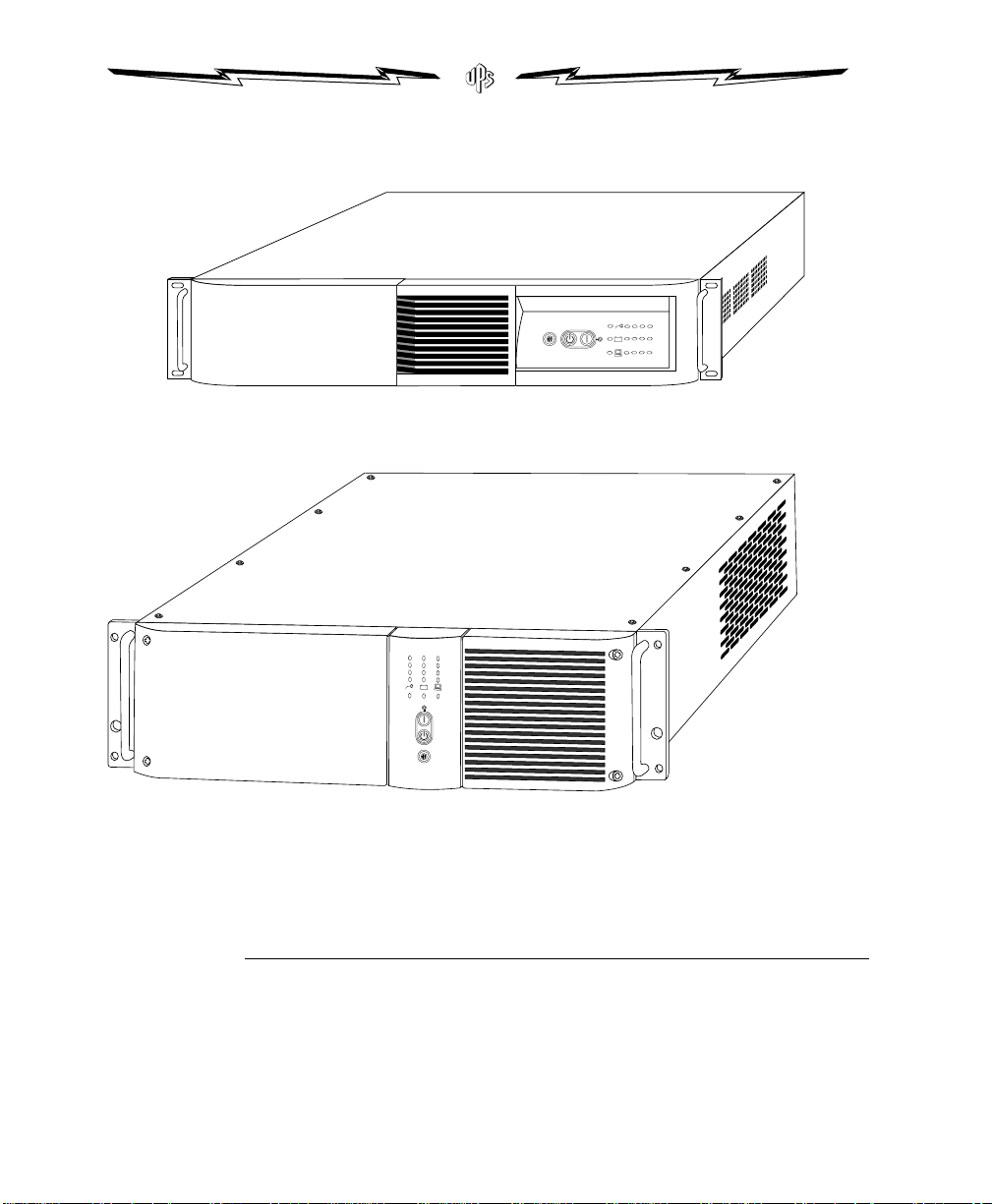
ACE1000a-RM, ACE1500a-RM, ACE1000i-RM, and ACE1500i-RM
ACE2000a-RM, ACE3000a-RM, ACE2000i-RM, ACE2400i-RM, and ACE3000i-RM
Figure 1. ACE Series Rack-Mount
How to Contact Us
PowerVar is committed to excellence in dependability and customer
satisfaction. If you have any questions about our products, please
contact us at: 847-816-8585 (fax: 847-816-8988).
2 Preface
Page 11

SECTION 1
IMPORTANT SAFETY INSTRUCTIONS
INSTALLATION
This section explains:
Inspecting equipment
Safety precautions
Installing your UPS
Inspecting Your Equipment
If any equipment has been damaged during shipment, keep the
shipping cartons and packing materials for the carrier or place of
purchase and file a claim for shipping damage. If you discover damage
after acceptance, file a claim for concealed damage.
To file a claim for shipping damage or concealed damage: 1) File with
the carrier within 15 days of receipt of the equipment; 2) Send a copy of
the damage claim within 15 days to your service representative.
Safety Precautions
Read the following before you install your UPS.
SAVE THESE INSTRUCTIONS. This manual contains important instructions that you should follow during
installation and maintenance of the UPS and batteries. Please read all instructions before operating the
equipment and save this manual for future reference.
ACE Series Rack-M o u n t • 05145651A 3
Page 12
WARNING
Electrical Energy Hazard. The battery pack contains HIGH ENERGY. To reduce the risk of electric shock,
WARNING
NOTE
use caution when you handle and interconnect the units.
If operating the UPS while it is unplugged from the source of electrical power, DO NOT make contact
with the line cord input pins. Electrical shock hazard exists.
To reduce the risk of fire or electric shock, install in a temperature- and humidity-controlled indoor area
free of conductive contaminants.
(VDE requirement) The sum of earth leakage current from all loads connected to the UPS must not
exceed 1.5 mA.
Mounting the UPS in a Rack
The UPS fits in a 19-inch rack. Follow the steps below to install the UPS
in the rack.
The UPS is heavy. It can be very awkward, and potentially dangerous, to handle. Therefore, it is mandatory
that a minimum of two people lift and place the UPS in its rack.
Disconnect all cables from the UPS before continuing. Remove all self-adhesive pads from the underside of
the unit, if already fitted.
1.Place the unit on a hard, flat surface with the front of the unit
facing toward you.
4 Section 1 • Installation
2.If the mounting brackets are not already installed, position a
mounting bracket over the mounting holes on one side of the
unit, as shown in Figure 2.
3.Insert the screws and fully tighten using a suitable screwdriver.
4.Repeat steps 2 and 3 for the other side of the unit.
5.Using at least two people, lift the unit and slide it into the rack.
6.Secure the UPS by screwing the mounting angles to the rack face
(screws not provided). The unit is now secured in the rack.
Page 13
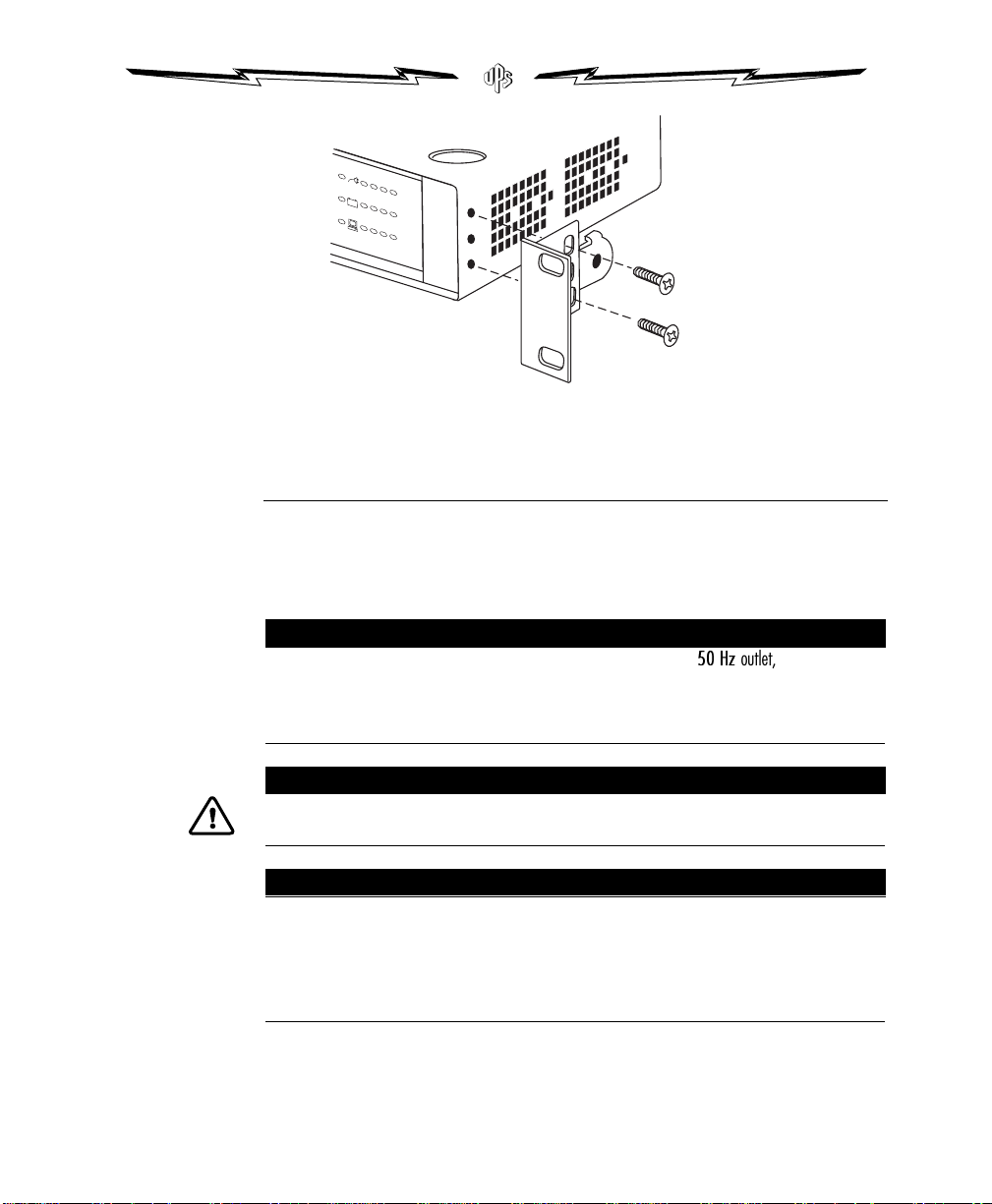
Figure 2. Attaching the Mounting Bracket
NOTE
CAUTION
NOTE
Installing the UPS
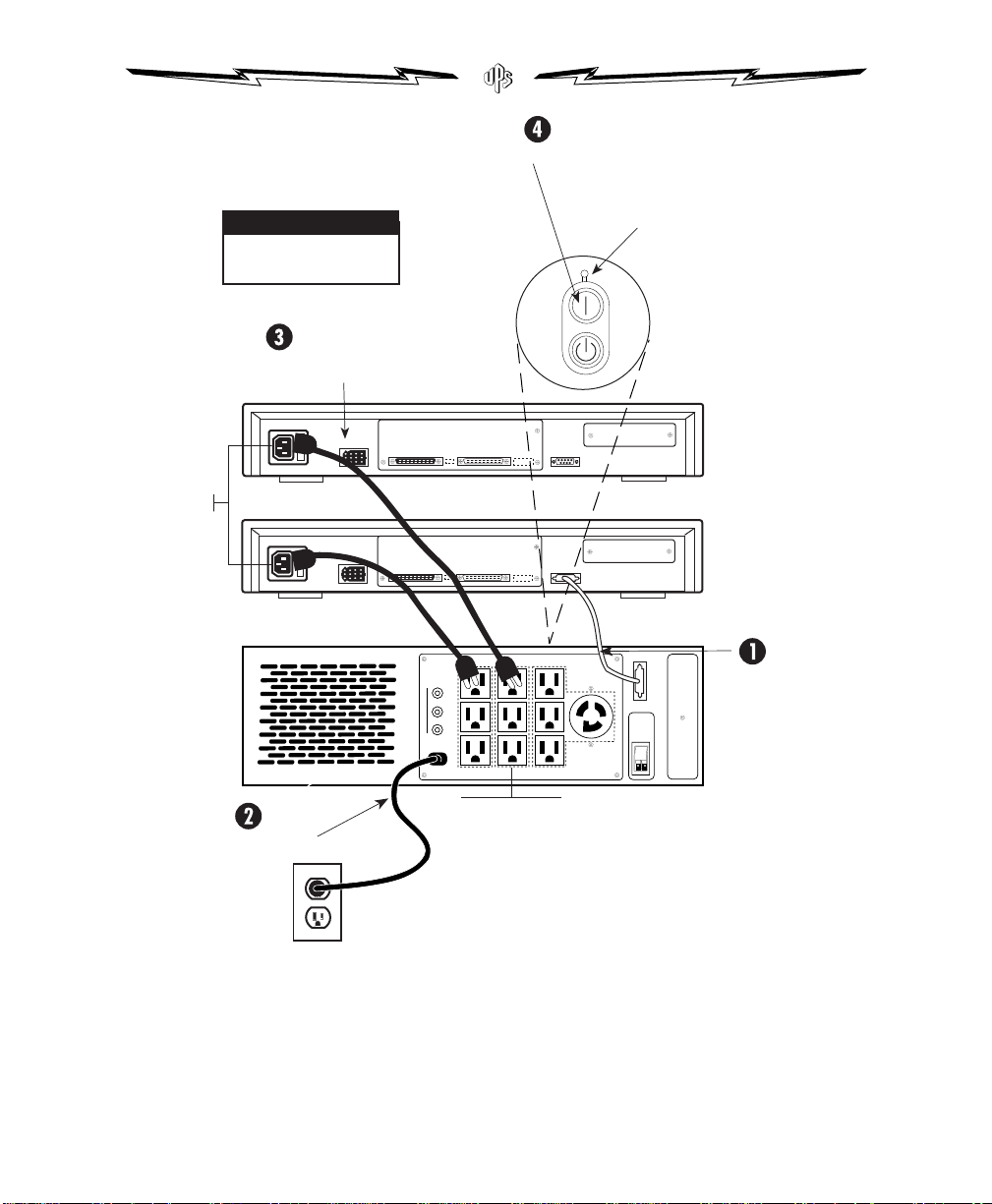
Follow these steps to install your UPS. Figure 3 shows a typical
installation; installing your specific model may vary. Appendix C
shows the rear panel of each model.
Some units may not recognize 50 Hz outlets. If you connect your UPS to a
start, press the ON button for 3 seconds to start the UPS on battery. Then configure the UPS input voltage
for either 100 V or 110 V (see Section 3, Configuration). The UPS recognizes the input line and goes off
battery.
DO NOT plug laser printers into a UPS. The high surge currents they produce can disrupt any manufacturer’s
UPS.
If your UPS output receptacles are divided into Load Segments, and you plan to take advantage of this
feature (available only with specific power management software), read the appropriate sections of
your power management software manual before you install the UPS.
Changes or modifications not expressly approved by the party responsible for compliance could void your
authority to operate the equipment.
ACE Series Rack-M o u n t • 05145651A 5
50 Hz
outlet, and it will not
Page 14
1. If you plan to use our power management software, connect
NOTE
your computer’s communication cable to the UPS RS-232 port.
2. Plug your UPS power cord into a wall outlet or other power
source.
If your UPS uses a customer-supplied power cord, it must be
correctly rated (see Appendix B, Specifications). You can also use
the power cord from your largest load if it is correctly rated.
Once the UPS is connected, it conducts a self-test and then goes
to Standby mode. If a red Site Wiring or Battery Service LED
stays on, consult Section 2, Operation, or S ection 5,
Troubleshooting.
3.Plug your loads (computer, monitor, etc.) into the UPS output
receptacles. Use the provided interconnecting line cords where
applicable.
4.Start the UPS by pressing the ON button as shown in Figure 3.
Power is now available to the rear receptacles, and the ON LED
is lit.
5.You have now completed installation. To learn how to operate
the UPS, see Section 2, Operation. To change the factory-set
defaults, see Section 3, Configuration.
The UPS will charge to 90% in approximately 4 hours. However, it is recommended that you charge for
24 hours after installation or long storage.
6 Section 1 • Installation
Page 15
NOTE
This is a typical setup;
your setup may vary.
Connect loads to UPS
Press ON button
ON LED
(LED 16)
Load
IEC Male Inlet
Load
UPS
Connect communications
cable from computer
to UPS (optional)
Output Receptacles
Connect UPS to power
Figure 3. Typical UPS Installation (low voltage model shown)
ACE Series Rack-M o u n t • 05145651A 7
Page 16

Page 17

SECTION 2
OPERATION
This section explains how to:
Turn the UPS on and off
Interpret the LED display
Put the UPS in Standby mode
Initiate the self-test
Silence an audible alarm
Turning the UPS On
Once the UPS is connected to a power source, it conducts a self-te st
and enters Standby mode. To turn the UPS on, press the ON button on
the front panel (shown in Figure 4). Power is now available at the rear
receptacles.
To turn the UPS on without using AC input, press the ON button for
3 seconds. When the UPS starts on battery, it conserves battery power
by not conducting a self-test.
Turning the UPS Off
To turn the UPS off, press the OFF/Standby button on the front panel
and unplug the UPS from the AC power source. If you do not unplug
the UPS, it remains in Standby mode.
Silencing an Audible Alarm
Press the Test/Alarm Reset button to silence an audible alarm.
Although you have silenced the alarm, you may still need to resolve
the problem which triggered the alarm. For more information, see
Section 5, Troubleshooting.
ACE Series Rack-M o u n t • 05145651A 9
Page 18
Interpreting the LED Display
NOTE
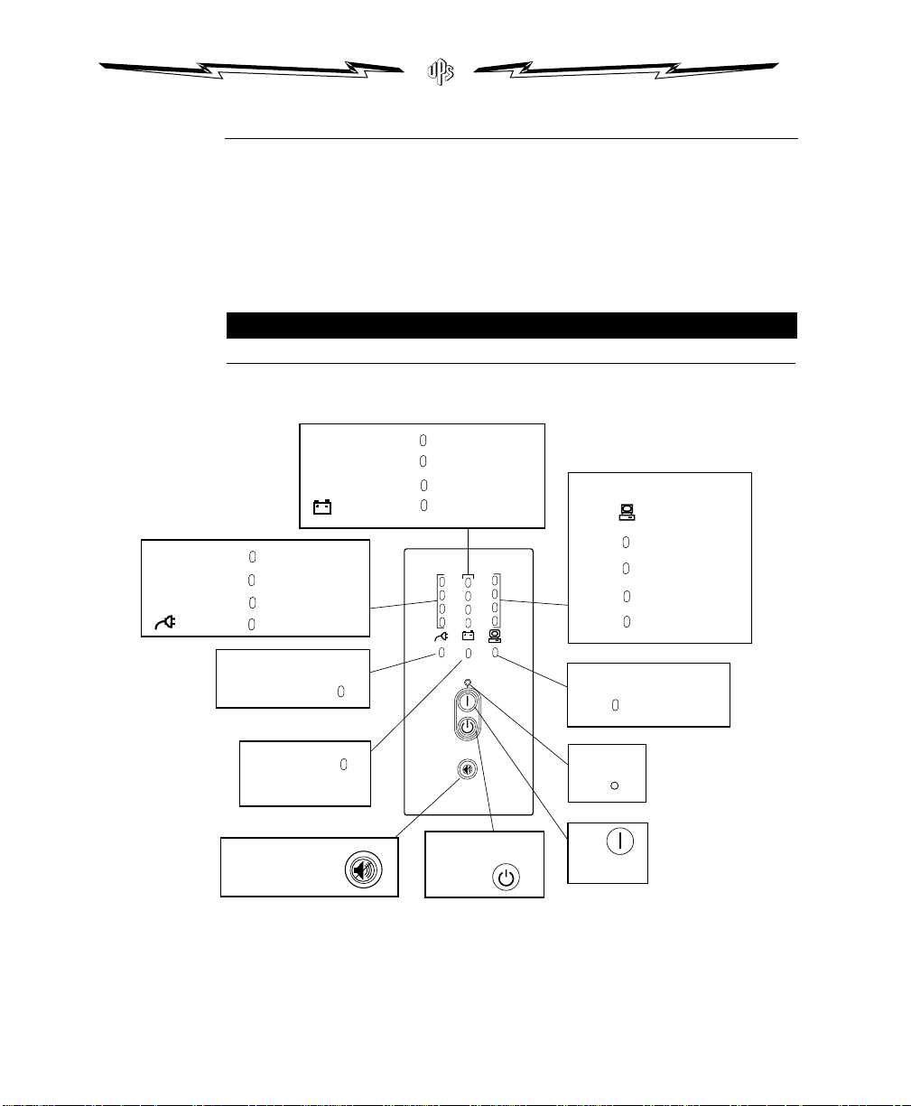
The front panel LEDs indicate how the UP S is functioning and also
warn about possible problems. Figure 4 and Table 1 explain how to
interpret the LEDs when the UPS is in Operation mode. When the UPS
is in Configuration mode, the front panel LEDs provide different
information. For more information about how to interpret LEDs when
the UPS is in Configuration mode, see Section 3, Configuration.
The front panel may be rotated clockwise 90 degrees on some models.
AC
Input
LEDs
Battery
Charge
LEDs
1
Red Input Too High
Green Input Normal
2
Green Double Boost On
3
Red Input Too Low
4
Site Wiring
5
Fault LED
Battery
Red
Red
Service LED
Test/Alarm
Reset Button
10
Green
Green
Green
Red
6
Battery >90%
Battery >66-90%
7
Battery >33-66%
8
Battery Low
9
OFF/Standby
Button
Load Levels
LEDs
11
Red
Green
Green
Green
Overload
12
Load >66-100%
13
Load >33-66%
Load 5-33%
14
Communication LED
15
Green
ON LED
16
Green
ON
Button
Figure 4. Interpreting LEDs in Operation Mode
10 Section 2 • Operation
Page 19

Table 1. Interpreting LEDs in Operation Mode
NOTE
Name NumberColor Explanation (if lit)
ON 16 Green Output voltage available at the rear outlets.
AC Input 1 Red Line voltage is too high; UPS battery provides all power.
2 Green Line voltage is normal; AC input provides all power.
3 Green Line voltage is lower than normal; AC input provides all power.
4 Red Line voltage is too low; UPS battery provides all power.
Site Wiring Fault 5 Red Ground wire connection doesn’t exist, or the line and neutral wires are reversed in the socket.
Battery Charge 6 Green Batteries are fully charged.
7 Green Battery charge is approximately 2/3 of full charge.
8 Green Battery charge is approximately 1/3 of full charge.
9 Red Low battery charge; there are approximately 3-5 minutes of battery backup remaining. If the
Battery Service 10 Red Potential battery failure.
Load Level 11 Red Load current exceeds full load.
12, 13, 14 Green The amount of load current or watts. Each LED represents 1/3 of a full load rating. When all three
Communication 15 Green The UPS has received a command from a computer to establish communication.
(Flashing) Data is being transferred via the Communication Port.
battery shuts down before AC input is restored, the load also shuts down.
LEDs are green, the load is approximately full.
Putting the UPS in Standby Mode
To put the UPS in Standby mode, press the OFF/Standby button. In
Standby mode, the battery recharges when necessary, but power is no
longer available at the rear receptacles.
Initiating the Self-Test
Press the Test/Alarm Reset Button for three seconds to initiate the selftest. During the test, individual LEDs turn on as various parts of the
UPS are checked. If the UPS finds a problem, an LED turns on to
indicate where the problem is. For more information, see Section 5,
Troubleshooting.
Batteries must be at least 90% charged (LEDs 6, 7, and 8 must be on) and the unit must be off battery, to
perform the self-test.
ACE Series Rack-M o u n t • 05145651A 11
Page 20

Page 21

SECTION 3
CONFIGURATION
This section explains:
Why you may want to change factory defaults
How to reconfigure func tions
Why Change Factory Defaults?
Input Nominal Voltage (LEDs 1, 2, 3, and 10)
If your AC input consistently fluctuates higher OR lower than the
factory-set nominal input voltage (higher than +20% OR lower than 30% of 120 V or 230 V nominal), your UPS maintains the selected
nominal input voltage by repeatedly switching to battery power. If this
creates a nuisance, you can configure the UPS nominal input voltage to
more closely match the nominal voltage of your AC input source.
Extended Nominal Voltage Range (LED 4)
If your AC input consistently fluctuates higher AND lower than the
factory-set nominal input voltage (higher than +20% AND lower than 30% of 120 V or 230 V nominal), your UPS maintains the selected
nominal input voltage by repeatedly switching to battery power. If this
creates a nuisance, you can configure the UPS nominal input voltage to
more closely match the wider range of your AC input source.
Other Settings
Reconfigure LEDs 5, 6, or 8 to change the alarms. Reconfigure LED 7 to
change the delay before unconditional shutdown. Reconfigure LED 9
so the UPS does not shut off power to the load when the UPS is on
battery power and the load is not drawing current. LEDs 11 through 14
are inactive and cannot be selected .
ACE Series Rack-M o u n t • 05145651A 13
Page 22
Reconfiguring Functions
CAUTION
NOTE
You can change the functions after switching the UPS from Operation
mode to Configuration mode. In Configuration mode the front-panel
LEDs represent changeable functions, and the control buttons turn
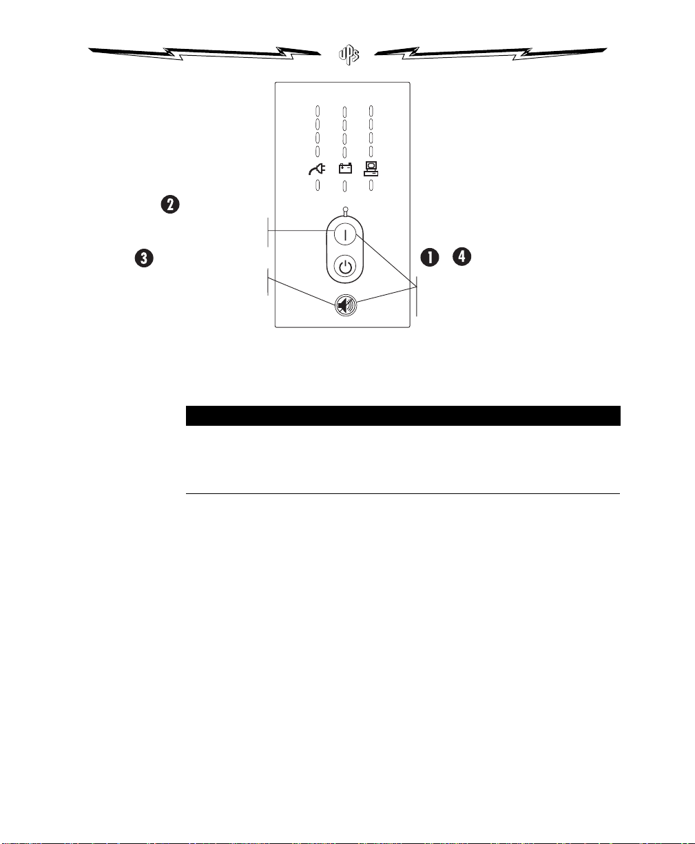
them on or off. Figure 5 shows the LED numbers, and Table 2 explains
the functions.
DO NOT press the UPS OFF button, while the UPS is in Configuration mode. The UPS will switch to Standby
and cut off all power to the attached loads.
1.Press the ON and Test/Alarm Reset buttons at the same time for
one beep. The unit goes to Configuration mode.
2.Press the ON button to scroll to the function you want to change.
The UPS beeps as you scroll through each function. The selected
function (LED) blinks. Figure 5 shows how the LEDs are
numbered. Table 2 describes the functions.
3.If you press the ON button and nothing happens, you are still in
Operation mode. Repeat step 1 for one beep ONLY to go to
Configuration mode, and then perform step 2.
4.Press the Test/Alarm Reset button ONCE to turn the selected
function on or off. LED 16 turns on when the function is on and
off when the function is off. S et the remaining functions as
desired.
5.Press the ON and Test/Alarm Reset buttons any time to return
to Operation mode. Scrolling through LED 15 also returns the
unit to Operation mode. Changes take effect immediately after
returning to Operation mode.
The front panel may be rotated clockwise 90 degrees on some models.
14 Section 3 • Configuration
Page 23
1
NOTE
2
3
4
5
12
7
13
8
14
9
15
10
11
6
Press the ON button once
to scroll to the next function.
Press the Test/Alarm Reset button
to turn a function on or off.
Figure 5. LED Function in Configuration Mode
The factory default nominal voltage for some models may be set for 100 or 208 VAC. (See the rating label
on the UPS rear panel). If this is the case, the default LEDs in Configuration mode are as follows: For low
voltage models, LED 1 is OFF and LED 10 is ON. For high voltage models, LED 1 is OFF, LED 5 is OFF, and
LED 10 is on.
16
&
Press the ON and Test/Alarm Reset
buttons to toggle between Configuration
and Operation modes.
ACE Series Rack-M o u n t • 05145651A 15
Page 24

Table 2. How to Interpret LEDs in Configuration Mode
LED Function LED 16 Explanation
1 120/230 Nom. ON (default) Nominal voltage on low voltage models is 120 V and on high voltage models is 230 V; all other
OFF Nominal voltage on low voltage models is NOT 120 V and on high voltage models is NOT 230 V;
2 110/220 Nom. ON Nominal voltage on low voltage models is 110 V and on high voltage models is 220 V; all other
OFF (default) Nominal voltage on low voltage models is NOT 110 V and on high voltage models is NOT 220 V;
3 127/240 Nom. ON Nominal voltage on low voltage models is 127 V and on high voltage models is 240 V; all other
OFF (default) Nominal voltage on low voltage models is NOT 127 V and on high voltage models is NOT 240 V;
4 Extended Voltage ON The UPS accepts an input voltage within -35% to +20% of the selected nominal input voltage before
OFF (default) The UPS accepts an input voltage within -30% to +20% of the selected nominal input voltage before
5 Wiring Fault
Alarm
6 Low Battery
Alarm
7 Shutdown Delay ON (default) 5-second delay before unconditional shutdown after UPS receives signal from a computer via
8 AC Input Failure ON (default) Alarm sounds when there is an AC input failure.
9 Sleep Mode ON (default) UPS shuts off power to load when the UPS is on battery power and load is not drawing current. This
10 100/208 Nom. ON If your unit is configurable for 100 V operation, when LEDs 10 and 16 are both on, the nominal
11-14 N/A Reserved for future use.
15 Reset Defaults ON (default) All factory-set defaults are active.
ON (default) Alarm sounds when the polarity of the input source is reversed or ground is missing; have a
OFF Alarm DOES NOT sound when the polarity of the input source is reversed or ground is missing.
ON (default) Alarm sounds 3 minutes before battery shutdown.
OFF Alarm sounds 5 minutes before battery shutdown.
OFF 180-second delay before unconditional shutdown after UPS receives signal from a computer via
OFF Alarm DOES NOT sound when there is an AC input failure.
OFF UPS DOES NOT shut off power to load when the UPS is on battery power and load is not drawing
OFF (default) Nominal voltage on 100 V models is NOT 100 V and on 208 V models is NOT 208 V; some other
OFF One or more factory-set defaults have been changed.
nominal input voltages are disabled.
some other nominal input voltage is selected.
nominal input voltages are disabled.
some other nominal input voltage is selected.
nominal input voltages are disabled.
some other nominal input voltage is selected.
switching to battery.
switching to battery.
qualified electrician repair input source.
Communication Port.
Communication Port. When this LED is not enabled, the user can also create a new delay time by
reconfiguring the Communication Port. See Appendix A, Additional UPS Features, for more
information.
feature saves battery power.
current.
voltage on 100 V models is 100 V and on 208 V models is 208 V; all other nominal input voltages
are disabled.
nominal input voltage is selected.
16 Section 3 • Configuration
Page 25
SECTION 4
WARNING
UPS CARE AND
BATTERY REPLACEMENT
This section explains how to:
Replace your batteries
Return your used batteries
Care for your UPS and batteries
Store your UPS
Replacing Batteries
Our hot-swappable battery feature allows you to replace your UPS
batteries easily without turning the UPS off or disconne cting the load.
The following section explains how.
When to Replace Batteries
When the Battery Service LED (LED 10) turns red, your batteries may
need replacing. Conduct a self-test by pressing the
Test/Alarm Reset button. If the LED stays on, contact your service
representative to order new batteries.
ELECTRIC ENERGY HAZARD. Do not attempt to alter wiring in either the battery connector or the battery
tray. Attempting to alter wiring can cause injury or death.
A battery can present a risk of high short circuit current which can cause burns. The following precautions
should be observed when working on batteries: 1) Remove watches, rings, or other metal objects;
2) Use tools with insulated handles; 3) Do not lay tools or metal parts on top of batteries.
The battery has no support when you pull it out of the UPS. Pull the battery out onto a flat, stable
surface.
ACE Series Rack-M o u n t • 05145651A 17
Page 26
CAUTION
When the UPS is on line, all three green Battery Charge LEDs (6, 7, 8) should be lit before replacing
CAUTION
(hot-swapping) the batteries. DO NOT DISCONNECT the batteries while the UPS is on battery power or
while the UPS is charging the batteries.
If you choose to unplug the UPS to change the battery: 1) Press the OFF button and remove input
power; 2) Wait 60 seconds while the internal microprocessor shuts down before you disconnect the
battery.
The UPS and its batteries are heavy. If your unit is installed in a rack, you must support the front of the unit
while replacing the batteries.
How to Replace Batteries
Figure 6 shows how to replace your UPS batteries. Consider all
warnings, cautions, and notes before replacing batteries.
18 Section 4 • UPS Care and Battery Replacement
Page 27

Figure 6. Replacing Batteries
Testing New Batteries
Press the Test/Alarm Reset button to start a self-test. The red Battery
Service LED (LED 10) should turn off and the Battery Charge LEDs
(LEDs 6, 7, and 8) should show a charge. If the red Battery Service LED
stays on, check the battery connections. If it remains on, see Section 5,
Troubleshooting, or call your service representative.
ACE Series Rack-M o u n t • 05145651A 19
Page 28
Returning the Used Battery
WARNING
CAUTION
Use the packaging from your new battery to return your old battery.
Call your service representative to get information about returning
your used battery.
Do not dispose of battery or batteries in a fire. Batteries may explode. Dead batteries are considered a
hazardous waste. Return batteries to the factory for proper disposal. It is illegal to dump or improperly
dispose of batteries.
Do not open or mutilate the battery or batteries. Released electrolyte is harmful to the skin and eyes. It
may be toxic.
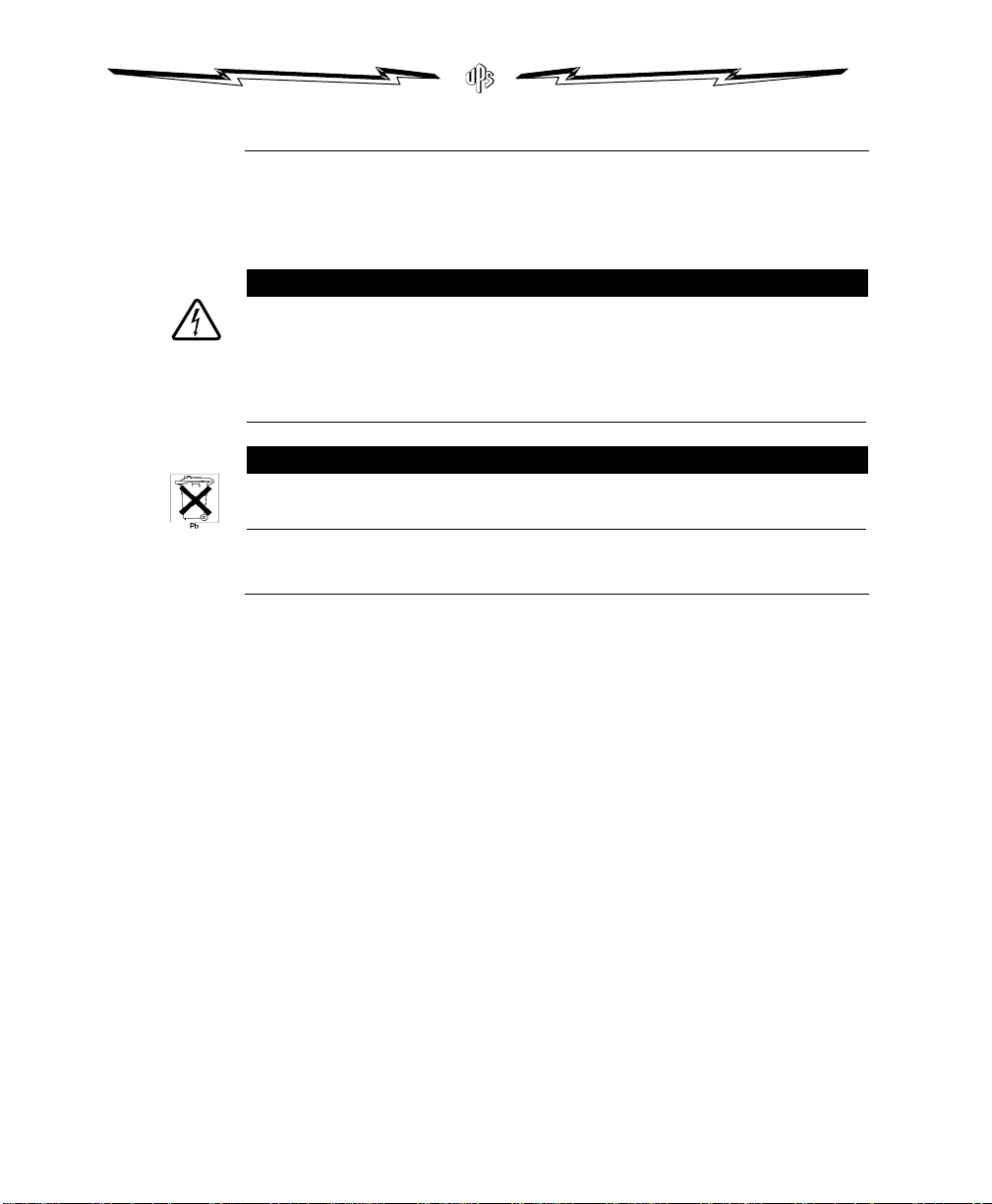
This product contains sealed, lead-acid batteries which must be recycled. For more information, contact your
local recycling center or your service representative.
UPS/Battery Care and Storage
For the best preventive maintenance, keep the area around the UPS
clean and dust-free. If the atmosphere is very dusty, clean the outside
of the system with a vacuum cleaner.
For full battery life, keep the UPS at an ambient temperature of 25°C
(77°F).
20 Section 4 • UPS Care and Battery Replacement
Storing the UPS
If you store the UPS for a long period, recharge the battery every six
months by plugging the UPS into a power outlet. The UPS will charge
in Standby mode. Charging takes 6 to 24 hours.
UPS Repairs
Repairs on your UPS must be performed by the factory or by factoryauthorized service locations. If you have any questions or problems,
please contact your service representative.
Page 29

SECTION 5
TROUBLESHOOTING
This section explains:
How to recognize the symptoms of UPS problems
The possible causes of UPS problems
How to correct UPS problems.
Table 3. Troubleshooting Guide
Symptom Possible Cause What To Do
LED 16 is not on; the UPS will
not start.
The UPS switches frequently
between battery and AC input.
The Low Battery Alarm does not
give enough warning.
LED 1 (AC Input, High) or
LED 4 (AC Input, Low) are on.
A circuit breaker or an input fuse on the rear
panel is open.
The line cord is not connected. Connect the line cord.
The wall outlet is dead. Have a qualified electrician test and repair the outlet.
The UPS may be unable to recognize a
100 V, 50 Hz wall outlet.
A battery fuse or circuit breaker is open. Contact your service representative.
Input voltage in your area differs from the
UPS nominal.
The batteries need charging or service. Plug the UPS into a wall outlet for 24 hours, to charge the battery;
The Low Battery Alarm is not set
appropriately.
The line voltage is too high or too low; the
UPS is running on battery power.
Push the circuit breaker button or replace the fuse (see Appendix
C, UPS Rear Panels).
See Appendix B, Specifications, to verify that your UPS accepts
100 V nominal input.
Unplug the UPS. Start the UPS on battery and reconfigure the
nominal input voltage for 100 V (see Section 3, Configuration).
Turn the UPS off for 3 seconds. Plug the UPS into an outlet.
Change the UPS nominal input to match your local nominal; see
Section 3, Configuration.
press the Test/Alarm Reset button for three seconds; then check
LED 10 (Battery Service).
Change the alarm setting. See Section 3, Configuration.
Correct the input voltage, if possible, or be prepared for a power
failure less than 5 minutes after LED 9 turns on (depending on
configuration, with normal load and ample charge).
If LED 1 or LED 4 are on continuously, the input voltage in your
area may differ from the UPS nominal. Change your UPS to match
your local conditions. See Section 3, Configuration, for more
information.
continued
ACE Series Rack-M o u n t • 05145651A 21
Page 30

Table 3. Troubleshooting Guide (continued)
Symptom Possible Cause What To Do
LED 5 (Site Wiring Fault) is on. There is no ground wire or ground connection
LED 9 (Battery Charge, Low)
is on.
LED 10 (Battery Service) is on,
or on only during startup.
LED 10 (Battery Service) is
flashing.
LED 11 (Load Level, Overload) is
on.
in the wall outlet.
The line and neutral wires are reversed in the
wall outlet.
The battery is running low. Less than 5 minutes of power remains (depending on
The battery may be fully discharged because
of a long storage period or failing because of
age.
The battery is not connected correctly. Check connections or call your service representative.
The DC voltage is high; the alarm won’t clear Contact your service representative.
The load is drawing too much power from the
UPS.
Have a qualified electrician establish a grounding connection.
Have a qualified electrician correct the wiring.
To disable this fault condition, see Section 3, Configuration.
configuration, with normal load and ample charge); prepare for a
power failure. Save your work and turn off your equipment.
Plug the UPS into a wall outlet for 24 hours to charge the battery.
Push the Test/Alarm Reset button, then check LED 10. If LED 10 is
still on, see Section 4, UPS Care and Battery Replacement, to
replace the battery.
Determine if the load is defective or if some of the load needs to
be disconnected.
22 Section 5 • Troubleshooting
Page 31
APPENDIX A
CAUTION
ADDITIONAL UPS FEATURES
This appendix explains:
How to use the UPS Communications capabilities
Where to find more information about Option Cards
Where to find more information about Load Segments
(may not be available on all units)
How to install the Remote Emergency Power Off
Communication Port Configurations
To establish communication between the UPS and a computer, plug
the UPS/Computer Interface Cable into the Comm Port. Use only the
factory-supplied cable and software. The UPS operates normally if you
do not use this port.
To prevent damage to your equipment, connect only a factory-supplied cable or a cable built to factory
specifications (see Table 4) to your RS-232 port. A standard serial cable may damage your computer.
As shown in Table 4, the communication port Pins 1 and 2 operate in
two modes. The first is Basic Alarms mode, which has AC fail alarm
and output shutdown. The second is Serial Data mode, which is UPS
Code II compliant.
The system always starts in Basic Alarms mode. When serial data is
received at Pin 1, the function of Pin 1 and Pin 2 changes to Serial Data
mode.
If serial data has not been received before going to battery power,
serial communications is disabled until AC input returns.
ACE Series Rack-M o u n t • 05145651A 23
Page 32
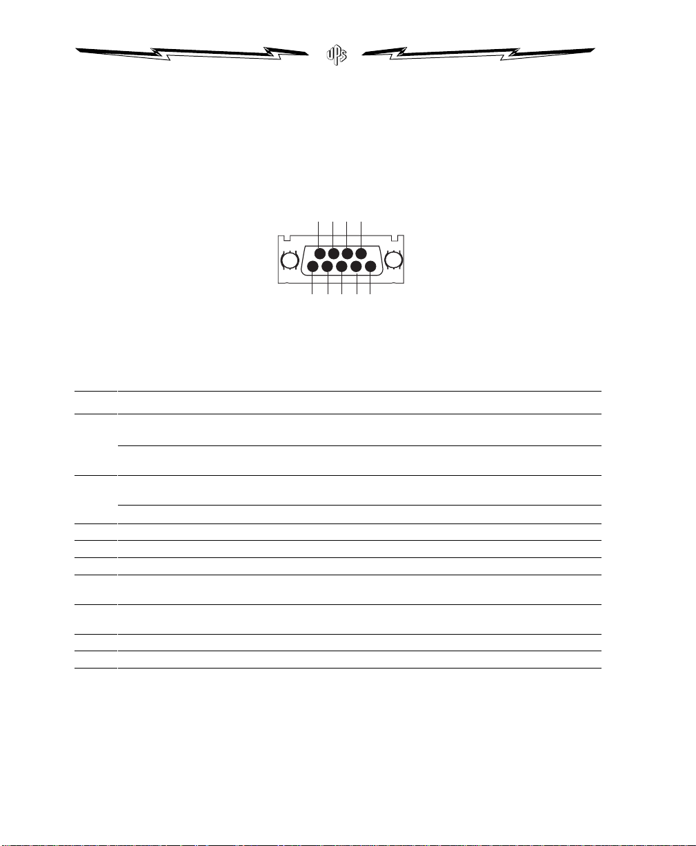
If the computer is running power management software, the interface
12345
6789
cable between the UPS and the computer’s Comm Port enables a data
exchange. Every 30 seconds, the software polls the UPS for detailed
information on the status of the power environment. If a power
emergency occurs, the software initiates the saving of all data and an
orderly shutdown of the equipment.
Figure 7. Communication Port
Table 4. Communication Port Configuration
Pin # Signal Type Function
1
2
3 Output: Open collector transistor ON, 50 mA, 40 VDC rating AC Input failure
4 Signal Common Signal Common
5 Output: Open collector transistor ON, 50 mA, 40 VDC rating Impending low battery
6 Input: RS-232 RTS Plug and Play software enable trigger (activates when pin changes
7 Input: Relay contact or RS-232 level Remote output OFF: UPS total output can be kept off with low
8 Output: 8 to 25 VDC, 5 W constant power (0.63 A max. @ 8 V) Auxiliary Control Power
9 Chassis Connection to chassis
Basic Alarms Mode — Input: RS-232 level low
(+12 V) pulse 4 to 5 seconds
Serial Data Mode — Input: RS-232 data
Basic Alarms Mode — Output: RS-232 level low
(+12 V)
Serial Data Mode — Output: RS-232 data
Remote UPS off: In absence of AC, output is turned off until
normal AC returns
RS-232 serial communication input. 1200 baud, 8-bit, no parity,
one stop bit, one start bit, Xon/Xoff
AC Input failure
RS-232 serial communication output. Same as input
from +12 V to -12 V)
signal or closing relay contact
24 Appendix A • Additional UPS Features
Page 33
Option Slot
WARNING
NOTE
The option slot accepts various installable option modules that help
your UPS communicate in a variety of networking environments. See
the manual that accompanies each module for more information, or
contact your sales representative.
Load Segments
Load Segments are sets of receptacles that can be turned on
individually using our power management software. For example,
during a power outage, you can keep key pieces of equipment running
while you turn off other equipment. This feature allows you to save
battery power. See your power management software manual for
details.
Remote Emergency Power Off (REPO)
The UPS has a REPO connector that can be wired to a device that can
be used to turn the UPS off from a remote location. The following
instructions explain how to wire the REPO switch.
Connect the REPO port to dry, isolated, normally-open contacts rated 60 VDC maximum, 30 VAC RMS
maximum, 20 mA maximum. Failure to conform to these guidelines may create dangerous conditions for
the operator by disabling the safety insulation of the equipment.
Activation takes place upon closing.
1.Remove the REPO connector from the REPO port on the rear
panel of the UPS.
2.Connect dry, isolated, normally-open contacts across the REPO
device to PIN 1 and PIN 2. (Figure 8 shows the location of the
pins on the UPS REPO connector.) Use stranded non-shielded
wiring, size #22 through #18.
3.Reconnect the REPO connector to the UPS.
ACE Series Rack-M o u n t • 05145651A 25
Page 34

Figure 8. REPO Port
26 Appendix A • Additional UPS Features
Page 35

APPENDIX B
NOTE
SPECIFICATIONS
For all of the models listed in Table 5, Model List, this appendix
provides detailed specifications for the following:
Electrical input and output
Battery
Weights and dimensions
Environmental and safety
ACE....a-RM and ACE....i-RM models are the same as PRC...a-RM and PRC....i-RM models.
Table 5. Model List
Feature Specification
UPS Models: Low Voltage Models
Battery Models: N/A. See Table 8
ACE1000a-RM
ACE1500a-RM
ACE2000a-RM
ACE3000a-RM
High Voltage Models
ACE1000i-RM
ACE1500i-RM
ACE2000i-RM
ACE2400i-RM
ACE3000i-RM
ACE Series Rack-M o u n t • 05145651A 27
Page 36

Table 6. Electrical Input
Feature Specification
Nominal Voltage: Low Voltage Models
120 V default; 100, 110, 120, 127 V selectable
Voltage Range: -30% to +20% at full load for nominal voltage; -35% to +20% user selectable, extended range
Nominal Frequency: Low Voltage Models
60 Hz; 50/60 if 100 V or 110 V selected
On-Line Efficiency: 96%
Noise Filtering: MOVs and line filter for normal and common mode noise
Connections: See Appendix C
High Voltage Models
230 V default; 208, 220, 230, 240 V selectable
High Voltage Models
50/60 Hz
Table 7. Electrical Output
Feature Specification
Power Levels
(rated at nominal
inputs):
Regulation On-Line: -10% to +6%; within Computer Business Equipment Manufacturers Association’s guidelines; (-15% to +10% using
Regulation On-Battery
(Nominal Voltage ±5%):
Voltage Wave Shape: Sine Wave; <3% distortion with linear load
Overcurrent Protection: On-Line: Resettable Circuit Breaker; On-Battery: Active current limit and short circuit protection
Connections: See Appendix C
Low Voltage Models
ACE1000a-RM: 1000 VA, 670 W
ACE1500a-RM: 1440 VA, 960 W
ACE2000a-RM: 1920 VA, 1400 W
ACE3000a-RM: 2880 VA, 2250 W
extended range)
Low Voltage Models
120 V for 110, 120, 127 V; 100 V for 100 V
High Voltage Models
ACE1000i-RM: 1000 VA, 670 W
ACE1500i-RM: 1500 VA, 960 W
ACE2000i-RM: 2000 VA, 1400 W
ACE2400i-RM: 2300 VA, 1600 W
ACE3000i-RM: 3000 VA, 2250 W
High Voltage Models
230 V for 220, 230, 240 V; 208 V for 208 V
Table 8. Battery
Feature Specification
Configurations: Internal batteries
Voltage: 24 VDC for ACE1000a-RM, ACE1500a-RM, ACE1000i-RM, and ACE1500i-RM
Type: Sealed, maintenance-free, valve-regulated, lead-acid
Charging: Advanced charging for faster recovery; less than 3 hours to 90% usable capacity at nominal line and no supplementary
Monitoring: Advanced monitoring for earlier failure detection and warning
Backup Time: At least 5 minutes at full load with a new battery at approximately 25°C
28 Appendix B • Specifications
48 VDC for ACE2000a-RM, ACE3000a-RM, ACE2000i-RM, ACE2400i-RM, and ACE3000i-RM
power supply load
Page 37

Table 9. Weights and Dimensions
Feature Specification
UPS Dimensions
(WxHxD):
UPS Weights: Low Voltage Models
ACE1000a-RM, ACE1500a-RM, ACE1000i-RM, ACE1500i-RM:
19.0 x 3.5 x 18.6 inches (48.2 x 8.9 x 47.2 cm)
ACE2000a-RM, ACE3000a-RM, ACE2000i-RM, ACE2400i-RM, ACE3000i-RM:
19.0 x 5.3 x 22.3 inches (48.2 x 13.3 x 56.6 cm)
ACE1000a-RM: 58 lbs. (26 kg)
ACE1500a-RM: 58 lbs. (26 kg)
ACE2000a-RM: 132 lbs. (60 kg)
ACE3000a-RM: 132 lbs. (60 kg)
Table 10. Environmental and Safety
Feature Specification
Operating Temp: 0°C to 40°C (32°F to 104°F); UL tested 25°C (77°F)
Storage Temp: -20°C to 60°C (-4°F to 140°F)
Relative Humidity: 5–95% non-condensing
Operating Altitude: Up to 3,000 meters above sea level
Audible Noise: Less than 45 dBA typical
Surge Suppression: IEEE C62.41 Category B
Safety Conformance: Low Voltage Models
Safety Markings: Low Voltage Models
EMC: Low Voltage Models
UL 1778, CSA C22.2, No. 107.1
UL, CSA
FCC, VCCI
High Voltage Models
ACE1000i-RM: 58 lbs. (26 kg)
ACE1500i-RM: 58 lbs. (26 kg)
ACE2000i-RM: 132 lbs. (60 kg)
ACE2400i-RM: 132 lbs. (60 kg)
ACE3000i-RM: 132 lbs. (60 kg)
High Voltage Models
EN 50091-1 and IEC 60950, UL 1778;
CSA C22.2, No. 107.1
High Voltage Models
CE, UL, and CSA
High Voltage Models
EN 55022, EN 50091-2
Table 11. Indicators and Controls
Feature Specification
Serial Communication: Intelligent serial communication to provide alarms with history, measured parameters, self-test, and many other
Interface: Ergonomic Indicators: Wiring Fault, Battery Service, Communication, Operation, System Normal
Contact Closures: Input Failure, Low Battery
features; contact your authorized dealer for UPS/computer communication software options
Bar Graphs: Input Level, Battery Charge Level, % Load
ACE Series Rack-M o u n t • 05145651A 29
Page 38

APPENDIX C
UPS REAR PANELS
This appendix shows the rear panels of all models discussed in this
handbook, including (where applicable):
Input and output receptacles, cords, and plugs
Circuit breakers and fuses
Comm ports ...
Figure 9. 1000 and 1500 VA, 120 V, Rear Panel
Figure 10. 2000 VA, 120 V, Rear Panel
30 Appendix C • UPS Rear Panels
Page 39

Figure 11. 3000 VA, 120 V, Rear Panel
Figure 12. 1000 and 1500 VA, 230 V, Rear Panel
ACE Series Rack-M o u n t • 05145651A 31
Page 40

Figure 13. 2000 and 2400 VA, 230 V, Rear Panel
Figure 14. 3000 VA, 230 V, Rear Panel
32 Appendix C • UPS Rear Panels
Page 41

PowerVar Standard Warranty
POWERVAR warrants its uninterruptible power supplie s or UPS (known hereafter as th e “product”) to be
free from defects in materials or wo rkmanship for a period of two years from the date of shipment. The
product will be repaired or (at POW ERVAR’s optio n) replaced at no cha rge durin g this warranty period.
Product must be returned prepaid to the factory.
POWERVAR makes no warranties, expressed or implied, of merchantability, fitness for a particular purpose,
performance, condition, capac it y or otherwise. POWERVAR is not liable for incidental or con se quential
damages, monetary loss, loss of sales, or loss of busin e ss resulting from t h e failure or malfunction of the
product. Warranty is void on any product that is misused, misapplied, abused, altered o r repaired by an y
unauthorized personnel or there evidence of tampering exists. The foregoing constitutes the sole and
exclusive remedy of the purchaser and is in lieu of all other Warranties. No greater degree of liability is
imposed on POWERVAR.
Page 42

Page 43

Page 44

05145651A
 Loading...