

Powervar ACE Series, ACE1000a-RM, ACE1500a-RM, ACE1000i-RM, ACE1500i-RM User Manual
...
PowerVar
28457 N. Ballard Drive
Lake Forest, IL 60045
Tel: 847-816-8585
Fax: 847-816-8988
PowerVar
ACE Series Rack-Mount
Uninterruptible
Power System
1000 – 3000 VA
05145651A Mar-98

Class A Statement for FCC and ICES
For Users in the United States Only
Note: This equipment has been tested and found to comply with the limits for a Class A digital device
pursuant to Part 15 of FCC Rules. These limits are designed to provide reason able protection again st
harmful interference when this equipment is operated in a commercial environment. This equipment
generates, uses, an d can radiate radio frequency energy and, if no t installed and used in accordance with the
instruction manual, may cause harmful interference to radio communications. Operation of this equipment
in a residential area is likely to cause harmful interference, in which case the user will be required to correct
the interference at his/her own expense.
Changes or modifications not expressly approved by the party responsible for compliance could void the
user’s a uthority to operate the equipment.
For Users in Canada
This Class A Interference Causing Equipment meets all requirements of the Canadian Interference Causing
Equipment Regulations ICES-003.
Cet appareil numerique de la classe A respecte toutes les exigences du Reglement sur le materiel brouileur
du Canada.
The following are examples of symbols
used to alert you to important information:
CAUTION
Risk of Electric Shock
Do Not Open Cover
CAUTION To reduce the risk of electric shock,
Do not remove cover (or back)
No user serviceable parts inside
Refer servicing to the factory
© 1998 PowerVar
This symbol is intended to alert you to the presence of uninsulated “dangerous voltage” within the product’s
enclosure that may be of sufficient magnitude to constitute a risk of electric shock.
This symbol is intended to alert you to the presence of important operating and maintenance (servicing) instructions
in the literature accompanying the appliance.
This symbol indicates that you should not discard the UPS or the UPS batteries in the trash. The UPS may contain
sealed, lead-acid batteries. Batteries must be recycled.
iii

How to Request a Declaration of Conformity
The EC Declaration of Conformity is available upon request for products with a CE mark. For copies of the
EC Declaration of Conformity, contact:
MPL House
Prescott Road
Poyle, Colnbrook
Berks SL3 OAE
UK
Phone: +44 1753 686200
Fax: +44 1753 686827
iv

Contents
PREFACE
ACE SERIES RACK-MOUNT — ONE OF THE BEST!................................................................1
How to Contact Us .....................................................................................................................................................2
SECTION 1
INSTALLATION.....................................................................................................................................................3
Inspecting Your Equipment ..........................................................................................................................................3
Safety Precautions......................................................................................................................................................3
Mounting the UPS in a Rack ........................................................................................................................................4
Installing the UPS.......................................................................................................................................................5
SECTION 2
OPERATION.........................................................................................................................................................9
Turning the UPS On....................................................................................................................................................9
Turning the UPS Off....................................................................................................................................................9
Silencing an Audible Alarm ..........................................................................................................................................9
Interpreting the LED Display.......................................................................................................................................10
Putting the UPS in Standby Mode...............................................................................................................................11
Initiating the Self-Test ...............................................................................................................................................11
SECTION 3
CONFIGURATION..........................................................................................................................................13
Why Change Factory Defaults? ..................................................................................................................................13
Input Nominal Voltage (LEDs 1, 2, 3, and 10) ......................................................................................................13
Extended Nominal Voltage Range (LED 4).............................................................................................................13
Other Settings....................................................................................................................................................13
Reconfiguring Functions.............................................................................................................................................14
SECTION 4
UPS CARE AND BATTERY REPLACEMENT....................................................................................17
Replacing Batteries...................................................................................................................................................17
When to Replace Batteries...................................................................................................................................17
How to Replace Batteries ....................................................................................................................................18
Testing New Batteries ...............................................................................................................................................19
Returning the Used Battery........................................................................................................................................20
UPS/Battery Care and Storage ..................................................................................................................................20
Storing the UPS .................................................................................................................................................20
UPS Repairs ......................................................................................................................................................20
v

SECTION 5
TROUBLESHOOTING.....................................................................................................................................21
APPENDIX A
ADDITIONAL UPS FEATURES................................................................................................................. 23
Communication Port Configurations ............................................................................................................................23
Option Slot .............................................................................................................................................................25
Load Segments........................................................................................................................................................25
Remote Emergency Power Off (REPO)........................................................................................................................ 25
APPENDIX B
SPECIFICATIONS.............................................................................................................................................27
APPENDIX C
UPS REAR PANELS.......................................................................................................................................30
vi

List of Figures
Figure 1. ACE Series Rack-Mount.................................................................................................................................2
Figure 2. Attaching the Mounting Bracket.....................................................................................................................5
Figure 3. Typical UPS Installation................................................................................................................................7
Figure 4. Interpreting LEDs in Operation Mode ............................................................................................................10
Figure 5. LED Function in Configuration Mode .............................................................................................................15
Figure 6. Replacing Batteries....................................................................................................................................19
Figure 7. Communication Port...................................................................................................................................24
Figure 8. REPO Port ................................................................................................................................................26
Figure 9. 1000 and 1500 VA, 120 V, Rear Panel......................................................................................................30
Figure 10. 2000 VA, 120 V, Rear Panel......................................................................................................................30
Figure 11. 3000 VA, 120 V, Rear Panel......................................................................................................................31
Figure 12. 1000 and 1500 VA, 230 V, Rear Panel......................................................................................................31
Figure 13. 2000 and 2400 VA, 230 V, Rear Panel......................................................................................................32
Figure 14. 3000 VA, 230 V, Rear Panel......................................................................................................................32
List of Tables
Table 1. Interpreting LEDs in Operation Mode ............................................................................................................11
Table 2. How to Interpret LEDs in Configuration Mode.................................................................................................16
Table 3. Troubleshooting Guide................................................................................................................................21
Table 4. Communication Port Configuration ...............................................................................................................24
Table 5. Model List ................................................................................................................................................27
Table 6. Electrical Input ..........................................................................................................................................28
Table 7. Electrical Output........................................................................................................................................28
Table 8. Battery ....................................................................................................................................................28
Table 9. Weights and Dimensions ............................................................................................................................29
Table 10. Environmental and Safety...........................................................................................................................29
Table 11. Indicators and Controls...............................................................................................................................29
vii


PREFACE
ACE SERIES RACK-MOUNT
— ONE OF THE BEST!
Congratulations on selecting the ACE Series Rack-Mount
uninterruptible power system (UPS) to protect your sensitive electronic
equipment from power disturbances and dirty power.
Because a power outage can occur when you least expect it —
threatening the loss of critical data — it’s important to protect your
network with a full-featured UPS such as the ACE Series Rack-Mount.
Network administrators often spend countless hours trying to
troubleshoot problems that, in many cases, would never have oc curred
had a UPS protected their network.
Properly installed, a UPS can be the single most cost-effective measure
you can take to ensure system security. Providing outstanding
performance and reliability, the ACE Series Rack-Mount’s unique
benefits include the following:
Advanced Battery Management (ABM™) doubles battery service
life, optimizes recharge time, and provides a warning up to 60 days
before the end of useful battery life.
Hot-swappable batteries simplify maintenance by allowing you to
safely replace batteries without powering down your critical load.
Network and modem protection (may not be available on your
model) guards your modem, fax machine, and other network
communications equipment from surges.
Buck and Double Boost regulation ensures consistent voltage to
your load by correcting voltage fluctuations without using battery
power.
Start-on-battery compatibility allows you to power up your UPS
even if utility power is not available.
Our power management software is fully compatible with the ACE
Series Rack-Mount and provides sequential orderly shutdown of all
network devices including multiple servers and workstations.
Optional power communication cards provide enhanced
communication capabilities for increased power protection and
longer battery backup times.
ACE Series Rack-M o u n t • 05145651A 1
Compact design conserves valuable space and makes the UPS easy
to install.
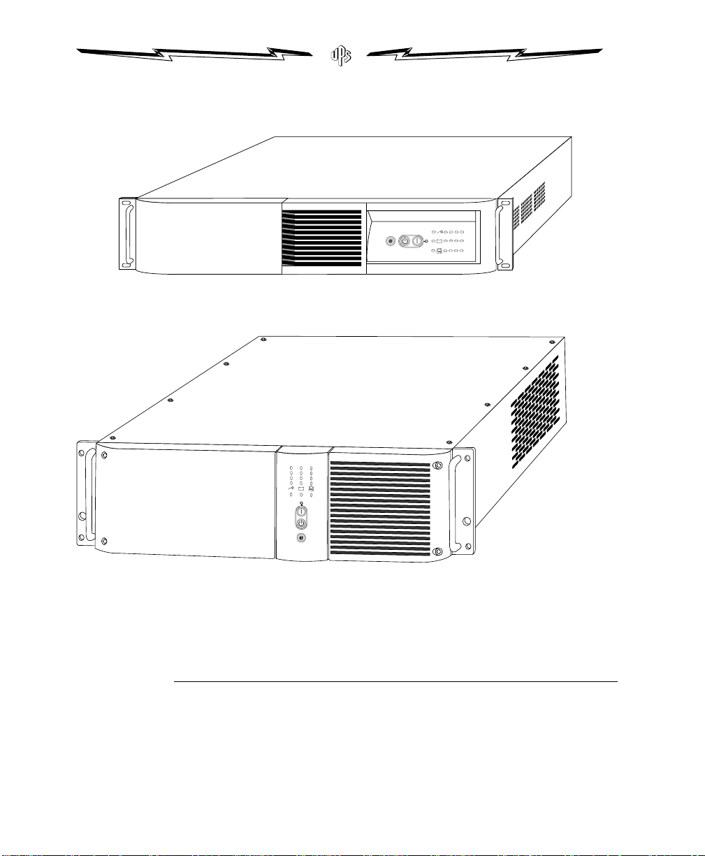
ACE1000a-RM, ACE1500a-RM, ACE1000i-RM, and ACE1500i-RM
ACE2000a-RM, ACE3000a-RM, ACE2000i-RM, ACE2400i-RM, and ACE3000i-RM
Figure 1. ACE Series Rack-Mount
How to Contact Us
PowerVar is committed to excellence in dependability and customer
satisfaction. If you have any questions about our products, please
contact us at: 847-816-8585 (fax: 847-816-8988).
2 Preface

SECTION 1
IMPORTANT SAFETY INSTRUCTIONS
INSTALLATION
This section explains:
Inspecting equipment
Safety precautions
Installing your UPS
Inspecting Your Equipment
If any equipment has been damaged during shipment, keep the
shipping cartons and packing materials for the carrier or place of
purchase and file a claim for shipping damage. If you discover damage
after acceptance, file a claim for concealed damage.
To file a claim for shipping damage or concealed damage: 1) File with
the carrier within 15 days of receipt of the equipment; 2) Send a copy of
the damage claim within 15 days to your service representative.
Safety Precautions
Read the following before you install your UPS.
SAVE THESE INSTRUCTIONS. This manual contains important instructions that you should follow during
installation and maintenance of the UPS and batteries. Please read all instructions before operating the
equipment and save this manual for future reference.
ACE Series Rack-M o u n t • 05145651A 3

WARNING
Electrical Energy Hazard. The battery pack contains HIGH ENERGY. To reduce the risk of electric shock,
WARNING
NOTE
use caution when you handle and interconnect the units.
If operating the UPS while it is unplugged from the source of electrical power, DO NOT make contact
with the line cord input pins. Electrical shock hazard exists.
To reduce the risk of fire or electric shock, install in a temperature- and humidity-controlled indoor area
free of conductive contaminants.
(VDE requirement) The sum of earth leakage current from all loads connected to the UPS must not
exceed 1.5 mA.
Mounting the UPS in a Rack
The UPS fits in a 19-inch rack. Follow the steps below to install the UPS
in the rack.
The UPS is heavy. It can be very awkward, and potentially dangerous, to handle. Therefore, it is mandatory
that a minimum of two people lift and place the UPS in its rack.
Disconnect all cables from the UPS before continuing. Remove all self-adhesive pads from the underside of
the unit, if already fitted.
1.Place the unit on a hard, flat surface with the front of the unit
facing toward you.
4 Section 1 • Installation
2.If the mounting brackets are not already installed, position a
mounting bracket over the mounting holes on one side of the
unit, as shown in Figure 2.
3.Insert the screws and fully tighten using a suitable screwdriver.
4.Repeat steps 2 and 3 for the other side of the unit.
5.Using at least two people, lift the unit and slide it into the rack.
6.Secure the UPS by screwing the mounting angles to the rack face
(screws not provided). The unit is now secured in the rack.
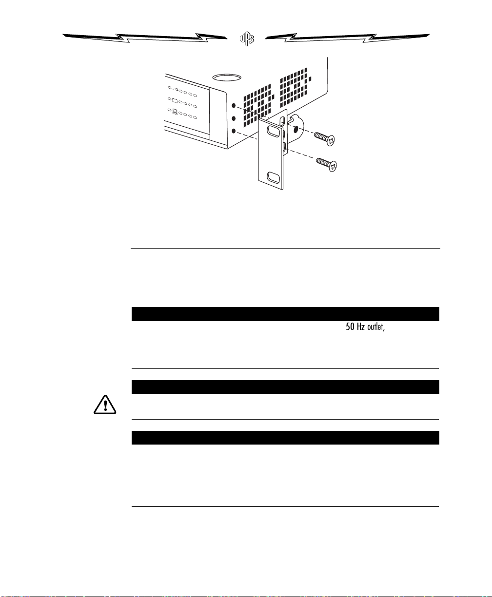
Figure 2. Attaching the Mounting Bracket
NOTE
CAUTION
NOTE
Installing the UPS
Follow these steps to install your UPS. Figure 3 shows a typical
installation; installing your specific model may vary. Appendix C
shows the rear panel of each model.
Some units may not recognize 50 Hz outlets. If you connect your UPS to a
start, press the ON button for 3 seconds to start the UPS on battery. Then configure the UPS input voltage
for either 100 V or 110 V (see Section 3, Configuration). The UPS recognizes the input line and goes off
battery.
DO NOT plug laser printers into a UPS. The high surge currents they produce can disrupt any manufacturer’s
UPS.
If your UPS output receptacles are divided into Load Segments, and you plan to take advantage of this
feature (available only with specific power management software), read the appropriate sections of
your power management software manual before you install the UPS.
Changes or modifications not expressly approved by the party responsible for compliance could void your
authority to operate the equipment.
ACE Series Rack-M o u n t • 05145651A 5
50 Hz
outlet, and it will not

1. If you plan to use our power management software, connect
NOTE
your computer’s communication cable to the UPS RS-232 port.
2. Plug your UPS power cord into a wall outlet or other power
source.
If your UPS uses a customer-supplied power cord, it must be
correctly rated (see Appendix B, Specifications). You can also use
the power cord from your largest load if it is correctly rated.
Once the UPS is connected, it conducts a self-test and then goes
to Standby mode. If a red Site Wiring or Battery Service LED
stays on, consult Section 2, Operation, or S ection 5,
Troubleshooting.
3.Plug your loads (computer, monitor, etc.) into the UPS output
receptacles. Use the provided interconnecting line cords where
applicable.
4.Start the UPS by pressing the ON button as shown in Figure 3.
Power is now available to the rear receptacles, and the ON LED
is lit.
5.You have now completed installation. To learn how to operate
the UPS, see Section 2, Operation. To change the factory-set
defaults, see Section 3, Configuration.
The UPS will charge to 90% in approximately 4 hours. However, it is recommended that you charge for
24 hours after installation or long storage.
6 Section 1 • Installation
 Loading...