

Powervar ACDEF700-11, ACDEF1000-11, ACDEF1500-11, ACDEF2000-11, ACDEF3000-11 User Instruction Manual
...
POWERVAR Sinergy III Rackmount / Tower User Instruction Manual
Sinergy III 120 Volt UPS
· ACDEF700-11 700 VA UPS
· ACDEF1000-11 1000 VA UPS · E024-12 External Battery Cabinet
· ACDEF1500-11 1500 VA UPS · E036-12 External Battery Cabinet
· ACDEF2000-11 2000 VA UPS · E048-12 External Battery Cabinet
· ACDEF3000-11 3000 VA UPS · E072-12 External Battery Cabinet
Sinergy III 200-240 Volt UPS
· ACDEF2000-22 2000 VA UPS · E048-12 External Battery Cabinet
· ACDEF3000-22 3000 VA UPS · E072-12 External Battery Cabinet
This manual contains important instructions for the Sinergy III UPS and External Battery
Cabinets. Follow these instructions during the unpacking, installation, and maintenance of the
UPS and the External Battery Cabinet. If you have a problem with the UPS or the battery
cabinet, please refer to this manual before calling technical support.
POWERVAR
1450 South Lakeside Drive
Waukegan, IL 60085-8301
T (847) 596-7000
(800) 369-7179
F (847) 596-7100
www.powervar.com
A01-00040 Rev. E

A01-00040 Rev. E

Table of Contents
1. Introduction ……………………………………………………………………………………………...
1.1 Technical Support ……………………………………….…………………………………….……...
1.2 FCC Compliance ……………………………………….……………………………………..……...
1.3 Safety Compliance ……………………………………….……………………………...…………...
1.4 About This Manual ……………………………………….………………………………..………...
1.5 Safety ……………………………………….……………………………………………………......
1.5.1 Safety Intended Use ……………………………………….………………….…………………...
1.5.2 General Warnings ……………………………………….……………………….………………...
1.5.3 Safety Notices ……………………………………….………………………………..…………...
1.5.4 Battery Safety ……………………………………….…………………………………..………...
1.5.5 Repacking of Unit ……………………………………….…………………………...…………...
2. Overview ………………………………………………………………………………………………….
2.1 UPS Devices and Batteries …………………………………………………………………………..
2.2 Packing List ………………………………………………………………………………………….
2.3 Storage ……………………………………………………………………………………………….
2.4 Recharging the UPS During Storage ………………………………………………………………..
2.5 Environmental Conditions …………………………………………………………………………...
2.6 Floor Loading ………………………………………………………………………………………..
2.7 Ventilation …………………………………………………………………………………………..
2.8 Rear Panel View ……………………………………………………………………………………..
2.8.1 Models : ACDEF700-11, ACDEF1000-11, ACDEF1500-11 ……………………………………..
2.8.2 Model : ACDEF2000-11 …………………………………………………………………………..
2.8.3 Model : ACDEF3000-11 …………………………………………………………………………..
2.8.4 Model : ACDEF2000-22 …………………………………………………………………………..
2.8.5 Model : ACDEF3000-22……………………………………………………………………………
2.8.4 External Battery Cabinet ………………………………………………………………………….
2.9 LCD Display …………………………………………………………………………………………
2.9.1 Rack Display ……………………………………………………………………………………….
2.9.2 Tower Display …………………………………………………………………………………….
2.10 LCD : Display and Functional Description …………………………………………………………
1
1
1
1
1
2
2
2
2
4
4
5
5
5
5
6
6
6
6
7
7
7
7
8
8
9
10
10
10
11
3. Installation ……………………………………………………………………………………………….
3.1 Tower Installation……………………………………………………………………………………..
3.2 Rack Installation …………………………………………………………………………………..….
3.2.1 Assembly Steps …………………………………………………………………………………….
3.3 Electrical Preparations ……………………………………………………………………………….
3.3.1 Battery Connections ………………………………………………………………………………..
4. Setting Up UPS Parameters …………………………………………………………………………...
4.1 Factory Default Settings ……………………………………………………………………………..
4.2 Changing Default Settings …………………………………………………………………………..
4.2.1 Output Voltage Setting (item 01) ………………………………………………………………….
4.2.2 Frequency Converter Enable/Disable (item 02) …………………………………………………..
4.2.3 Output Frequency Setting (item 03) ……………………………………………………………….
4.2.4 Bypass Mode Enable/Disable when the UPS is off (item 06) …………………………..………...
4.2.5 Programmable Outlets Enable/Disable (item 07) …………………………………………………
4.2.6 Programmable Outlets Setting (item 08)………………………………………………..…………
4.2.7 LCD Display Direction Setting (item 09) ………………………………………………………...
4.2.8 Acceptable Input Voltage Range Setting (item 10) ……………………………………………….
4.2.9 Number of External Battery Cabinets (item 11) …………………………………………………..
A01-00040 Rev. E
12
12
13
13
15
15
17
17
17
18
18
19
19
19
20
20
20
20

5. UPS Operation ………………………………………………………………………………………….
5.1 UPS input connection ………………………………………………………………………………...
5.1.1 LCD Display in Bypass Mode………………………………………………………………………
5.1.2 LCD Display in Standby Mode……………………………………………………………………..
5.2 Turn on the UPS (Put the UPS in OnLine Mode) ……………………………………………………
5.2.1 LCD Display in OnLine Mode ……………………………………………………………………..
5.3 Connect Devices to the UPS …………………………………………………………………………
5.4 The UPS in Battery Mode ……………………………………………………………………………
5.4.1 LCD Display in Battery Mode ……………………………………………………………………..
5.5 Turn off the UPS ……………………………………………………………………………………..
6. Interfaces ………………………………………………………………………………………………..
6.1 Serial Interface COM 3…………………………………………………………… ………… …… ….
6.2 Interface Slot COM …………………………………………………………………………………..
7. Emergency Power Off (EPO) ………………………………………………………………………….
8. Maintenance …………………………………………………… ……………………………………….
8.1 Cleaning ……………………………………………………………………………………………...
8.2 UPS Storage …………………………………………………………………………………….……
8.3 Battery Testing ……………………………………………………………………………………….
8.4 Replacing Batteries…………………………………………………………………………………...
9. Troubleshooting………………………………………………………………………………………...
9.1 Troubleshooting Table………………………………………………………………………………..
9.2 Audible Alarm………………………………………………………………………………………..
9.3 LCD Display Abbreviation Index………………………………………… ………………………….
9.4 Warning Indicators……………………………………………………………………………………
9.5 UPS Fault……………………………………………………………………………………………..
9.5.1 LCD Display in Fault Mode………………………………………………………………………..
9.5.2 Fault Reference Code………………………………………………………………………………
21
21
21
21
22
22
22
23
23
23
24
24
24
25
25
25
25
25
26
29
29
31
31
32
33
33
33
10. Appendix A: Specifications………………………………………………………………………..……
10.1 SINERGY III UPS (100 - 120 Volt UPS) Specifications ………………………………………….
10.2 SINERGY III UPS (200 - 240 Volt UPS) Specifications ………………………………………….
10.3 Extension battery cabinets for use with Sinergy III UPS’s ………………………………………….
11. Appendix B: Optional Isolated Relay Contacts Card ………………………………………………..
11.1 Description…………….…………………………………………………………………………......
11.2 Installation in Sinergy III UPS accessory slot .……………………………………………………….
11.3 Isolated Relay Contact Card Operation …..…………………………………………………………..
11.4 Isolated Relay Contact Card Functional Diagrams …………………………………………………..
11.5 Isolated Relay Contact Card Specifications ………………………………………………………….
11.6
Instructions for Nortel Meridian PBX Systems ………………………………………………………………….
12. Appendix C: Warranty………………………………………………………………………………..
12.1 Basic Warranty…………………………………………………………………………………......
12.2 Limitations………………………………………………………………………………………….
12.3 Battery Life Disclaimer…………………………………………………………………………….
A01-00040 Rev. E
34
34
44
48
55
55
55
56
57
58
58
59
59
59
59

1. Introduction
Thank you for selecting this uninterruptible power supply (UPS). POWERVAR’s Sinergy III Series UPS offers the
most reliable protection from the harmful effects of electrical line disturbances for your computing and communi-
cations equipment. POWERVAR’s ISO 9001 certification represents our commitment to building world-class
products. We take pride in every unit that leaves our facility.
1.1 Technical Support
POWERVAR offers 24-hour technical support. To contact POWERVAR :
T (847) 596-7000
(800) 369-7179
F (847) 596-7100
Please check with technical support before attempting to repair or return any POWERVAR product. If a POWERVAR UPS needs repair or replacement, technical support will issue a return material authorization (RMA) number
along with instructions on how to return the UPS.
1.2 FCC Compliance
ATTENTION: Changes or modifications to this unit not expressly approved by the party responsible
or in FCC compliance could void the user’s authority to operate the equipment.
The 700-3kVA models have been tested and comply with the limits for a Class A digital device,
pursuant to Part 15 of FCC Rules. These limits are designed to provide reasonable protection against
harmful interference when the UPS is operating in a commercial environment. The UPS generates, uses,
and can radiate radio frequency energy. If installation and use is not in accordance with the instruction
manual, it may cause harmful interference to radio communications.
1.3 Safety Compliance
UL/cUL listing to UL1778, 4th Edition
CE
CAN/CSA C22.2 No 170.3-05, 2nd Edition
1.4 About This Manual
This manual contains information regarding the installation, operation, and maintenance of the uninterruptible
power supply (UPS).
The following symbols are used in this manual:
ATTENTION: Indicates instructions, which if not observed, may endanger reliability of your UPS or
security of your data.
CAUTION: Indicates instructions, which if not observed, present risk of electric shock, may endanger
your life, your health, reliability of your UPS or the security of your data.
1

1.5 Safety
1.5.1 Safety Intended Use
·
ance with all relevant safety regulations concerning information technology equipment for use in
an office environment.
be connected. These battery extensions may only be connected to the compatible basic UPS unit.
1.5.2 General Warnings
CAUTION: POWERVAR considers the safety of personnel to be of paramount importance. For this
reason it is essential that procedures relating to safety in this manual be carefully reviewed before
commencing work , and properly adhered to later. The user or operator may intervene in the opera tion of the UPS provided that the instructions laid out in Section 3 “ Installation” are
strictly followed.
This device serves as an uninterruptible power supply for connected loads. The device is in compli-
· Depending on the type and rating of UPS device, certain configurations of battery extensions may
CAUTION: Even when all switches and/or circuit breakers are open, dangerous voltages are
present within this unit! There are no user-serviceable parts inside. Only factory authorized technical
personnel may carry out any operation that requires protection panels to be opened and/or removed.
Any repairs or modifications by the user may result in out-of-warranty repair charges, unsafe electrical
conditions, or violation of electrical codes.
1.5.3 Safety Notices
IMPORTANT SAFETY INSTRUCTIONS
SAVE THESE INSTRUCTIONS
CAUTION: SAVE THESE INSTRUCTIONS - This Manual Contains Important Instructions that
should be followed during installation and maintenance of the UPS and batteries.
· For PLUGGABLE EQUIPMENT, the socket-outlet shall be installed near the equipment and shall
be easily accessible.
· CAUTION: To reduce the risk of fire, connect model ACDEF3000-11 only to a circuit provided
with 30 amperes maximum branch circuit overcurrent protection in accordance with the National
Electric Code, ANSI/NFPA 70.
· CAUTION: To reduce the risk of fire, connect models ACDEF700-11, ACDEF1000-11,
ACDEF1500-11, and ACDEF2000-11 only to a circuit provided with 20 amperes maximum branch
circuit overcurrent protection in accordance with the National Electric Code, ANSI/NFPA 70.
· Temperature Rating - Units are acceptable for use in a maximum ambient of 40 °C (104°F).
2

· The units are heavy. Lifting the units into the rack requires a minimum of two people.
· When installing units in racks, do not allow racks to become “top heavy”. Install heaviest equip-
ment (typically the external battery cabinet) near bottom of rack, and install this equipment before
installing equipment higher in the rack.
· This equipment services power from more than one source. The output terminals and/or receptacles
may have voltage present even when the unit is unplugged. UPS’s present a different safety issue
than most electrical equipment because unplugging the UPS puts it into battery mode. Unplugging
the UPS does not remove the electrical charge.
· The UPS must be connected to an earthed mains outlet-socket.
· When installing the equipment, ensure that the sum of the leakage current of the UPS and the con-
nected devices does not exceed 3.5mA.
· Make sure that no objects (e.g. pins, necklaces, paper clips, etc.) get inside the device. In emergen-
cies (e.g. damaged case, controls or power cables, penetration of liquids or foreign matter) switch
off the device and contact technical support for assistance.
· Transport the unit only in suitable packaging (protected against jolts and shocks).
may occur. Before you switch on the equipment it must be absolutely dry. An acclimatization pe riod of at least two hours is required.
· If the equipment is moved from a cold environment to a warmer operation location, condensation
the power supply, follow the instructions in Section 3 “Installation”.
· Do not connect equipment that will overload the UPS or demand DC-current.
· Place all cords so that nobody can stand on or trip over them. When connecting the device to
When this connection is open, the logic circuit will immediately shut down the UPS output.
· When cleaning the unit, follow the instructions in Section 8 “Maintenance”.
· Emergency power off (EPO) is located on the rear of the unit (see Section 2.7 “Rear Panel View”).
3

1.5.4 Battery Safety
IMPORTANT SAFETY INSTRUCTIONS
SAVE THESE INSTRUCTIONS
CAUTION: The batteries installed in the UPS and within the extended battery cabinets contain electro-
lyte. Under normal conditions the containers are dry. A damaged battery may leak electrolyte that can
be dangerous when in contact with the skin and cause irritation to the eyes. Should this happen, wash
the affected part with copious amounts of water and seek immediate medical attention.
· Even when discharged, a battery has the capacity to supply a high short circuit current, which in
addition to causing damage to the battery itself and to associated cables, may expose the operator to
the risk of burns.
charged (having been charged to 100% at the beginning of any such period). If these conditions are
not respected, the performance of the battery can no longer be guaranteed. It is advisable to recharge
the batteries at least once every 4 months.
carry out a number of discharge/recharge cycles before optimum performance is achieved.
governing disposal/recycling of toxic and harmful waste.
· Voltage is always present on the battery terminals.
· Batteries should not be kept in storage for periods exceeding 6 months at 25°C without being re-
· Since new batteries often do not provide full capacity after an initial charge, it may be necessary to
· In order to protect the environment, batteries must be disposed of in accordance with the regulations
1.5.5 Repacking of Unit
Do not pack equipment until at least two (2) hours have elapsed since the last recharge.
Place the equipment in bags made of material sufficiently porous to allow it to breathe (e.g. 100μm polyethylene).
Do not remove air from the packaging.
When packing the unit for movement by common carrier, place in original or equivalent packaging container.
4

2. Overview
NOTE: The equipment has been thoroughly checked before shipment. Upon receipt, check the packaging and en-
sure that the contents are undamaged and that no items are discarded. Any damage must be reported to the shipper
and any missing parts must be reported to the supplier immediately. Please keep the original package in a safe
place for future use.
2.1 UPS Devices and Batteries
The following table provides an overview of the various versions of the device:
Sinergy III UPS Model Battery Cabinet Model
ACDEF700-11 E024-12
ACDEF1000-11 E024-12
ACDEF1500-11 E036-12
ACDEF2000-11 E048-12
ACDEF3000-11 E072-12
ACDEF2000-22 E048-12
ACDEF3000-22 E072-12
2.2 Packing List
Unpack the package and check the package contents. The shipping package contains:
UPS Shipping Package Optional Extended Battery Cabinet
1. One UPS 1. One Battery Cabinet
2. One User Manual 2. One Battery Cable
3. Mounting Ears 3. Mounting Ears
4. Two Sets of Tower Stands (Feet) 4. Two Sets of Tower Stands (Feet and Extensions)
5. Rail Kit 5. Rail Kit
6. USB Cable
2.3 Storage
If the UPS is to be stored prior to use, it should be stored in a clean, dry environment and away from temperature
extremes. It is recommended that the equipment be stored in a temperature controlled, moderate humidity environment. The table below provides the temperature and humidity storage limits:
Storage Data
Temperature Limits 32°F to 104°F (0°C to +40°C)
Relative Humidity (Non-Condensing) 0% to 90%
NOTE: When storing equipment, every 8°C above 25°C reduces the shelf life of the battery by 50%. More
frequent battery charging is required to maintain the batteries in storage at these greater temperatures.
5

2.4 Recharging the UPS During Storage
Before storing, charge the UPS for five hours. During storage, recharge the battery in accordance with the following table:
Storage Temperature Recharge Frequency Charging Duration
-13°F to 104°F (-25°C to +40°C) Every 3 Months 1-2 Hours
104°F to 113°F (40°C to +45°C) Every 2 Months 1-2 Hours
2.5 Environmental Conditions
The UPS must be installed on a level and even surface. Install in an area protected from extremes of temperature,
water, humidity and the presence of conductive powder or dust. Do not stack units and do not place any objects on
top of a unit.
The functional temperature range of the UPS is 32°F to 104°F (0°C to +40°C).
The ideal ambient temperature range is 60°F to 77°F (15°C to 25°C).
Expected battery runtimes and battery life is based on operational temperatures between 68°F and 77°F (20°C and
25°C). Operation of the equipment above 77°F (25°C) reduces the service life of the batteries dramatically.
2.6 Floor Loading
Taking into consideration the weight of the UPS, extended battery cabinets, and any other equipment that may be
mounted in an associated rack. Confirm that the floor chosen location is capable of supporting the weight of the
combined units.
2.7 Ventilation
It is necessary to leave a minimum space of at least two inches (50 mm) in front and rear of the UPS to allow a
flow of air.
6
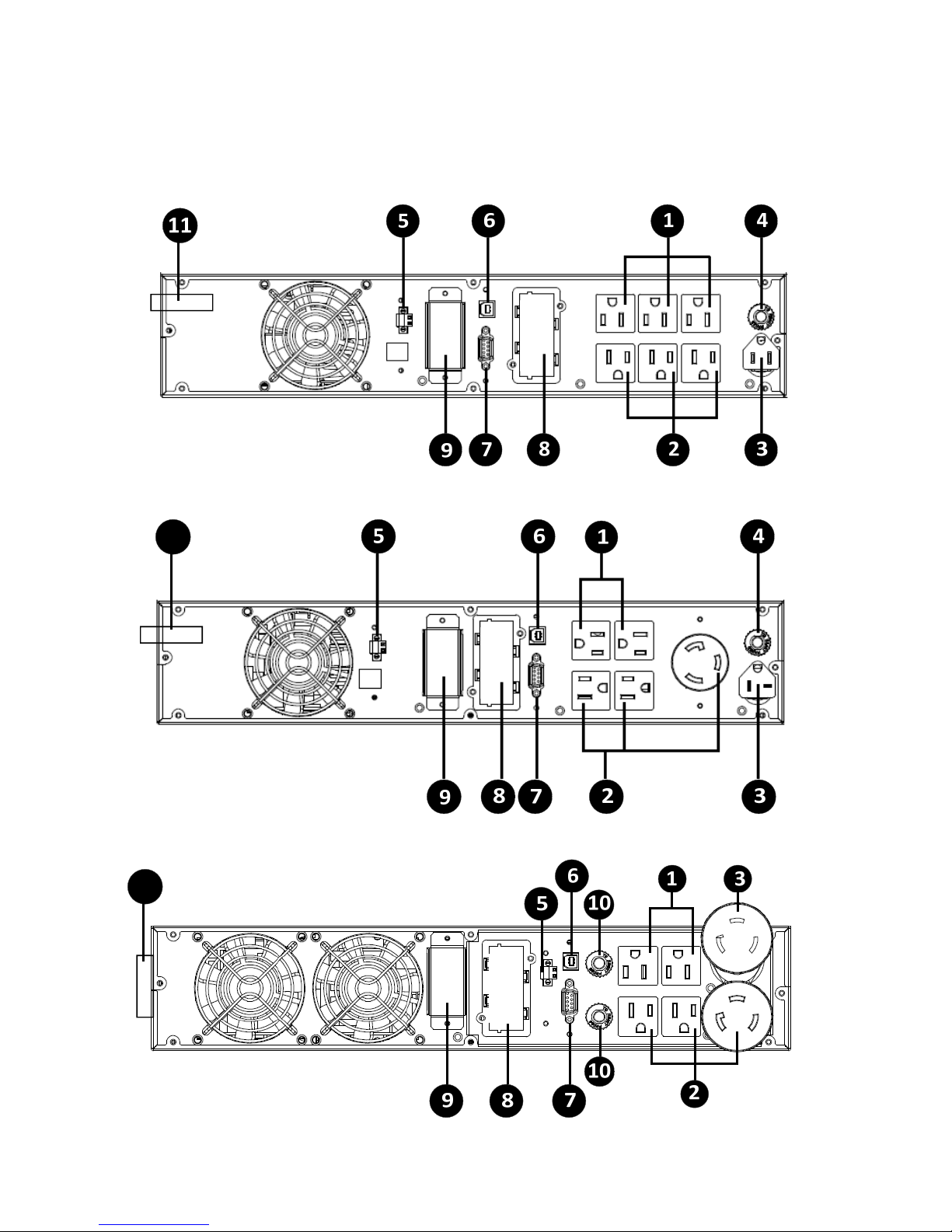
2.8 Rear Panel View
2.8.1 Models : ACDEF700-11, ACDEF1000-11 and ACDEF1500-11
2.8.2 Model : ACDEF2000-11
11
2.8.3 Model : ACDEF3000-11
11
7
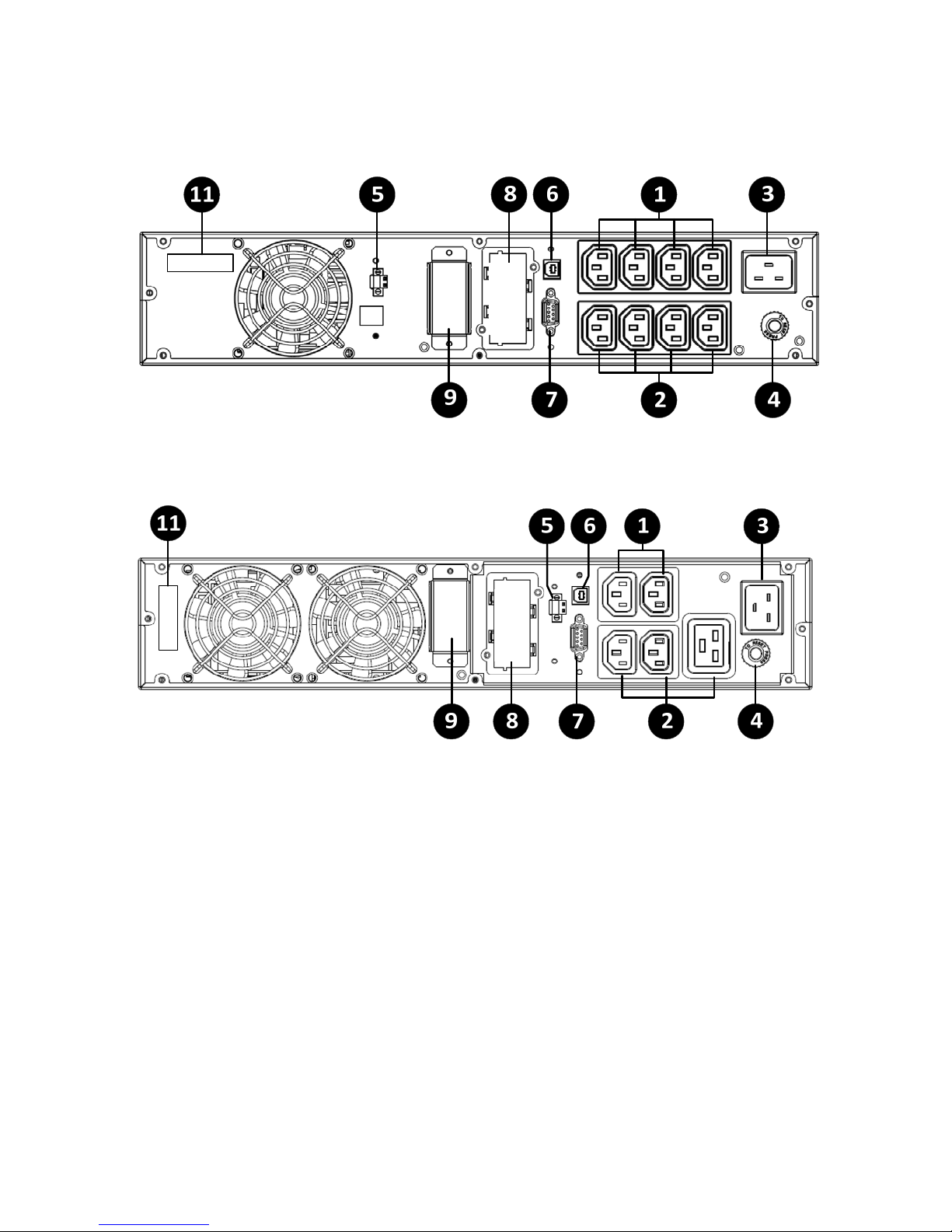
2.8.4 Model : ACDEF2000-22
2.8.5 Model : ACDEF3000-22
1. Programmable Output Receptacles
2. Direct Output Receptacles
3. AC Input
4. Input Circuit Breaker
5. Emergency Power Off Function Connector (EPO)
6. USB Communication Port
7. RS232 Communication Port
8. SNMP Intelligent Slot
9. External Battery Connector
10. Output Circuit Breaker
11. Serial Number
8
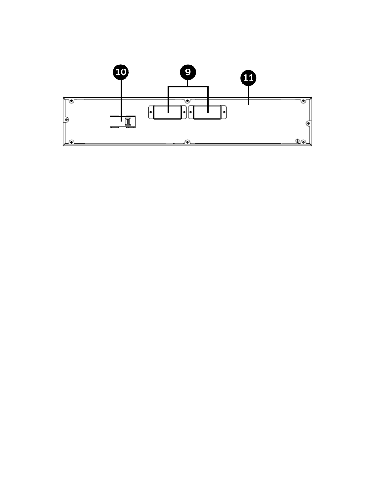
2.8.4 External Battery Cabinet
9. External Battery Connector
10. Output Circuit Breaker
11. Serial Number
9
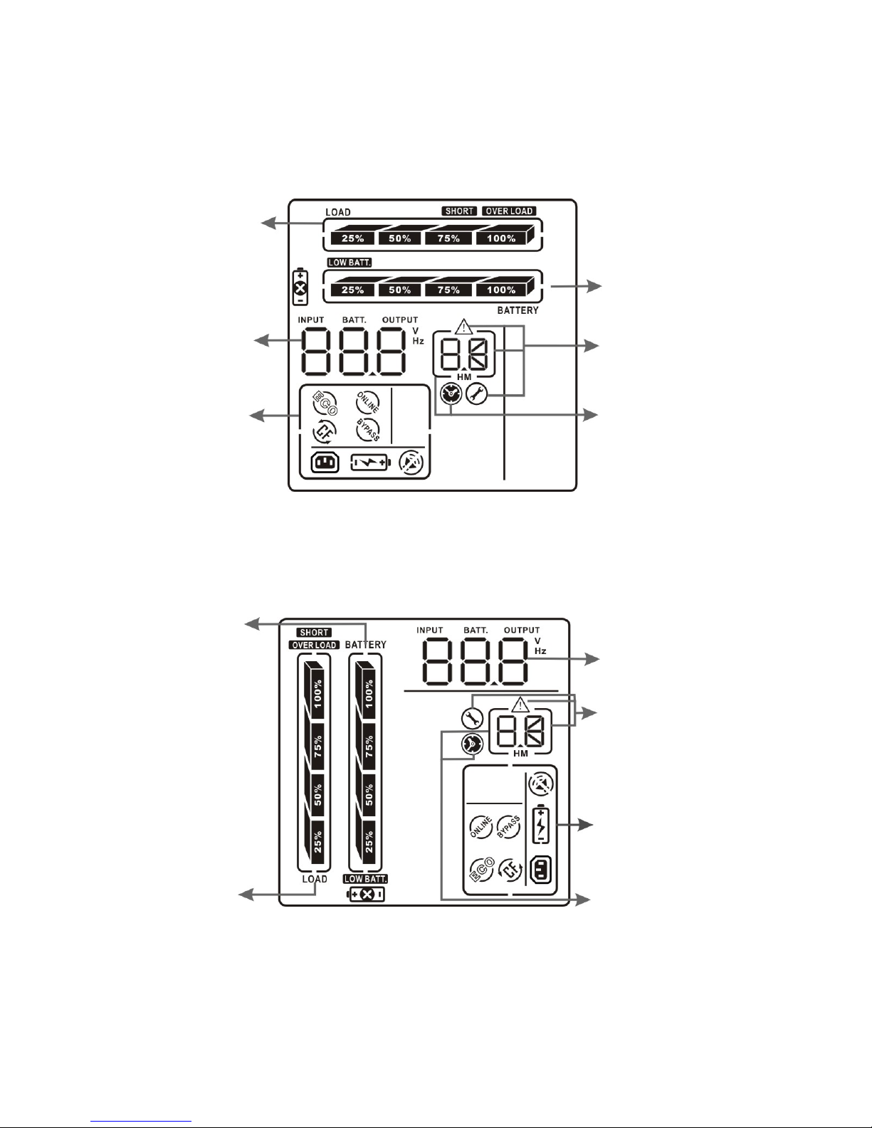
2.9 LCD Display
2.9.1 Rack Display
Load Info
Input/Output
and Battery
Info
UPS Status
Battery Info
Warning & Fault
Info/Setting
Operation
Backup
Time Info
2.9.2 Tower Display
Battery Info
Load Info
Input/Output
and Battery Info
Warning & Fault Info/
Setting Operation
UPS Status
Backup
Time Info
10
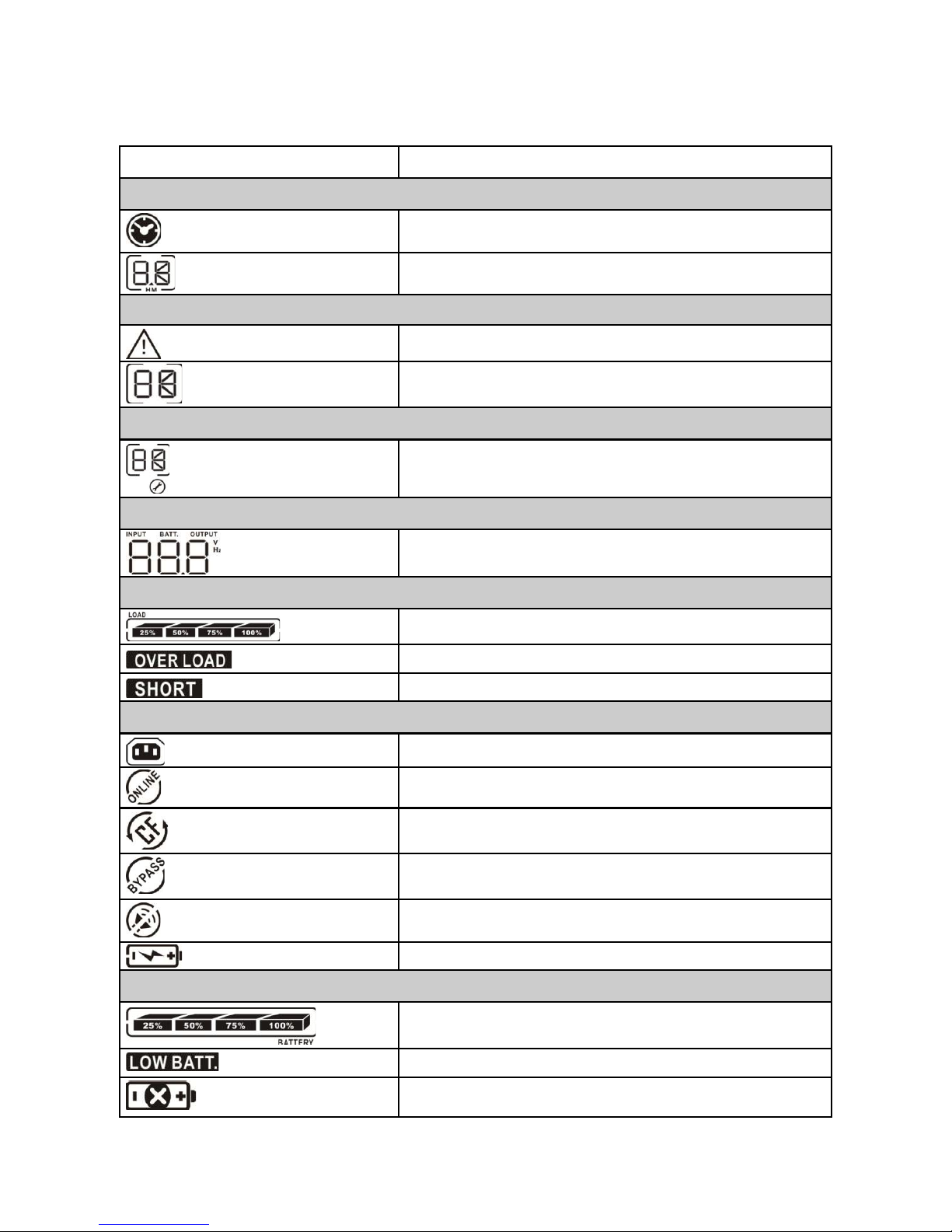
2.10 LCD : Display and Functional Description
Display Function
Backup time information
Indicates the backup time.
Indicates the backup time. H: hours, M: minutes
Warning & Fault information
Indicates that a warning and/or fault has occurred.
Indicates the warning and fault codes. The codes are listed in
Setting Operation
Indicates the setting information.
Input/Output & Battery information
Indicates the input/output voltage, input/output frequency, and
Load information
Indicates load level by 0-25%, 26-50%, 51-75% and 76-100%.
sections 9.4 and 9.5.
battery voltage. V: voltage, Hz: frequency
Indicates overload.
Indicates that the load or the UPS output is short circuited.
UPS Status
Indicates that the programmable outlets are working.
Indicates that the UPS is in on-line mode.
Indicates that the UPS is in converter mode.
Indicates that the UPS is in bypass mode.
Indicates that the UPS alarm is disabled.
Indicates that the battery charger is working.
Battery information
Indicates the battery level by 0-25%, 26-50%, 51-75%, and 76 -
Indicates low battery.
Indicates that there is something wrong with the battery.
100%.
11
3. Installation
The UPS and external battery cabinet are designed to be rack-mounted in four post frames or to be floor standing
in a tower configuration.
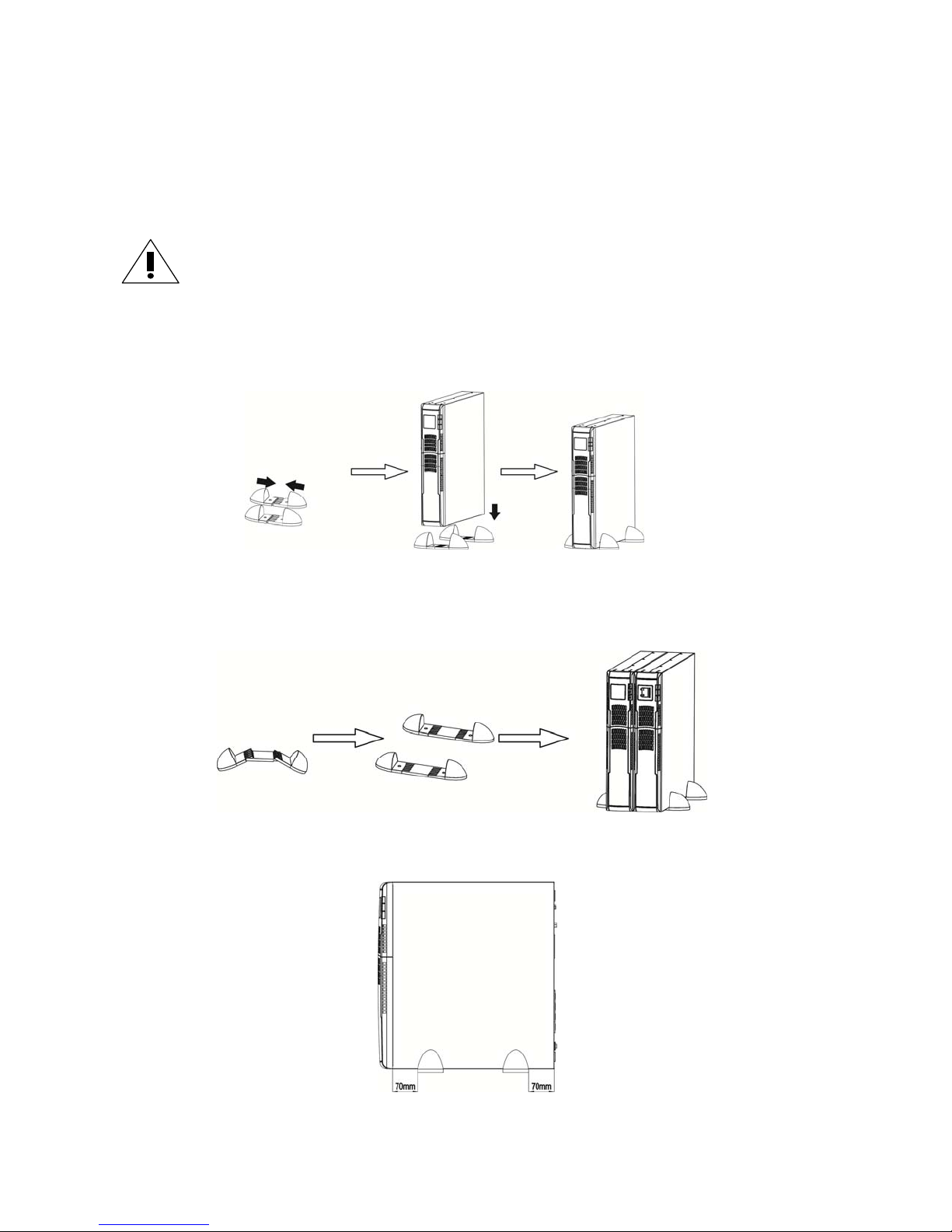
3.1 Tower Installation
A. To install standalone, refer to the figure directly below :
Assemble two feet as one tower stand.
Align the two stands.
Put the UPS module in the stands.
B. To install a UPS module and one extended battery cabinet, refer to the figure directly below :
Assemble two feet each with an extension as one tower stand.
Align the two stands.
Put the UPS module and external battery cabinet in the stands.
NOTE: When installing the UPS or external battery cabinet with feet, please keep both feet a distance of 2.75in
(70mm) from the edge of the unit. See figure below :
ATTENTION: Use all supplied mounting hardware on each UPS and extended battery cabinet.
12
3.2 Rack Installation
The UPS and the external battery cabinets are designed to be rack-mounted in four post frames. The UPS and external battery cabinet use identical mounting hardware and procedures.
NOTE: The rack-mount UPS draws air from the front. If the rack has a door on the front, make sure
that there is some clearance between the UPS vents and the rack door.
Because of the weight of these units, two people are recommended to lift and hold into position while all fasteners
are secured. Please use the supplied fasteners to attach the supplied mounting brackets to the UPS or external battery cabinet.
If external batteries are included in your installation, please mount them first and as low as possible. Start with the
lowest available position and work up. Your UPS should be installed last and end up on the top of all the battery
cabinets for proper cable routing.
ATTENTION: Use all supplied mounting hardware on each UPS and external battery cabinet.
NEVER depend on lower devices to support other devices.
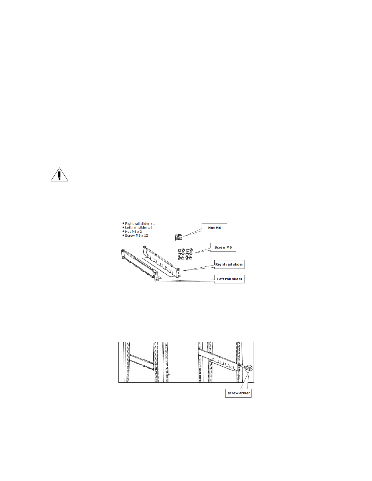
Included in each rack-mount carton is a rail kit. The rail kit consists of the following components :
3.2.1 Assembly Steps
Step 1: Use four M6 screws to mount the right and left rail sliders to the two front posts of the four-post rack.
Refer to the figure directly below :
13
Step 2. Use four M6 screws to mount the right and left rail sliders to the two back posts of the four-post rack.
Refer to the figure directly below :
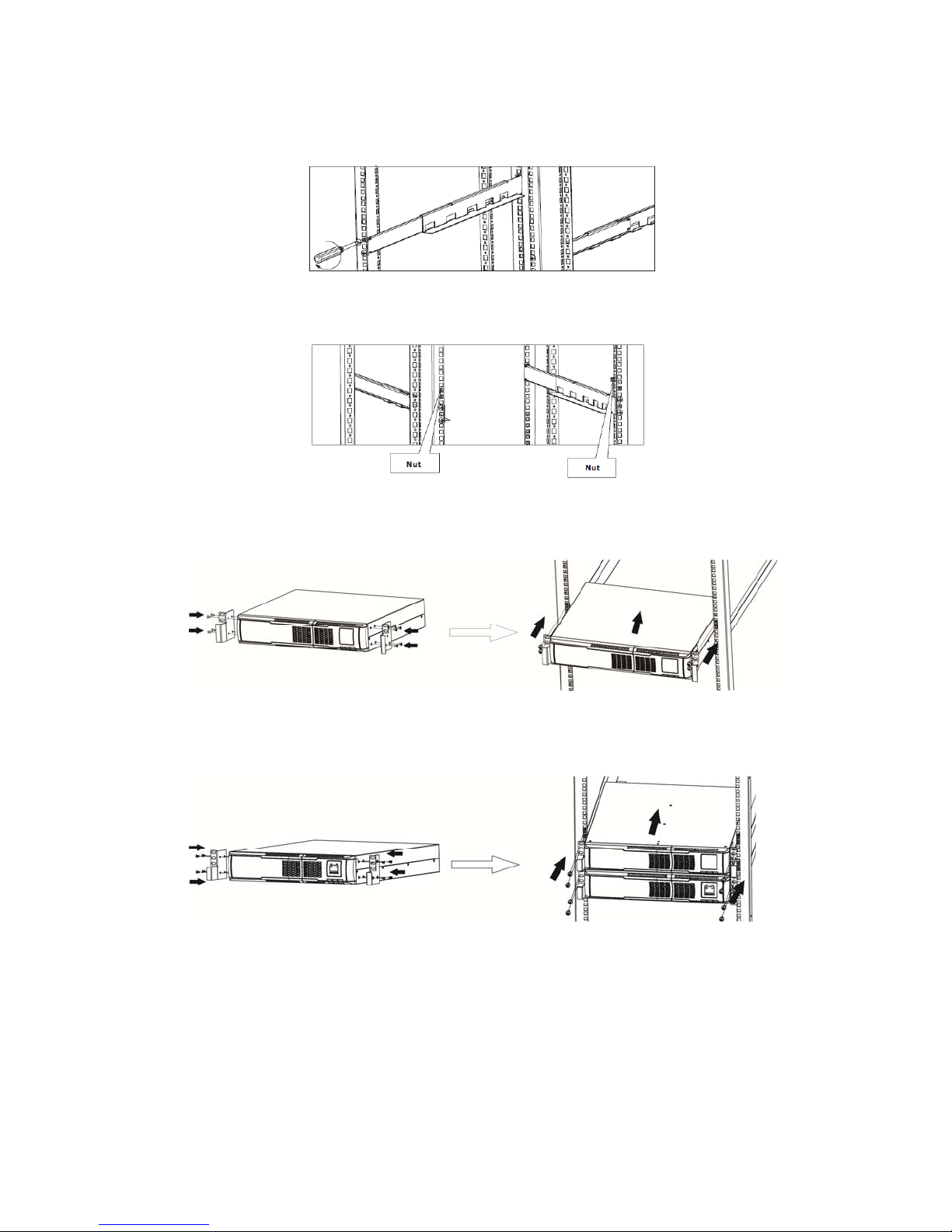
Step 3. Insert one M6 nut into the right and left front posts of the four-post rack for a 2U installation.
Refer to figure directly below :
Step 4. Install UPS alone.
Add mounting ears to both sides of the unit and refer to figure directly below :
Step 5. Install UPS and external battery cabinet.
Refer to figure directly below :
14

3.3 Electrical Preparations
CAUTION: Before connecting any input wiring to the UPS, take precautions to ensure that all cir-
cuits being used are the proper voltage and current required for the UPS.
CAUTION: UPS output receptacles are energized when the UPS is connected to the mains and the
bypass is enabled.
CAUTION: Electrical shock hazard. Even when the UPS is disconnected from the mains, hazardous
voltages may still exist at the output receptacles of the UPS. The UPS receives power from more than
one source - AC input and DC input from batteries. All input sources (AC and DC) must be discon
nected before carrying out maintenance work inside the UPS.
3.3.1 Battery Connections
CAUTION: Column one in the table below lists each of the UPS models and column two displays the
corresponding model of the extended battery cabinet which must be used with the UPS. DO NOT
USE any other extended battery cabinet for the corresponding UPS.
UPS Model Battery Cabinet Model
ACDEF700-11 E024-12
ACDEF1000-11 E024-12
ACDEF1500-11 E036-12
ACDEF2000-11 E048-12
ACDEF3000-11 E072-12
ACDEF2000-22 E048-12
ACDEF3000-22 E072-12
CAUTION: Before connecting a battery cabinet to the UPS, the circuit breaker of the battery pack
must be switched to “OFF”. After electrical connection with the UPS is established, the breaker must
be switched to “ON”.
15
 Loading...