

Powervar ABCE702-11R, ABCE702-11RMED, ABCE702-22R, ABCE702-22RMED, ABCE1002-11R Instruction Manual
...
Security II Rackmount Series
Uninterruptible Power Manager
For use with 700VA, 1000VA, 1440VA, 2200VA and 3000VA

2
A01-00071 Rev Fwww.powervar.com
1.0 - Introduction .................................................................... 6
2.0 - Safety Instructions ......................................................... 8
3.0 - Installation ..................................................................... 12
4.0 - Operation ....................................................................... 17
5.0 - Maintenance .................................................................. 22
6.0 - Troubleshooting ............................................................. 27
7.0 - Warranty ........................................................................ 29
8.0 - Specications ................................................................ 30
TABLE OF CONTENTS

3
A01-00071 Rev F www.powervar.com
IMPORTANT NOTICE ON BATTERY WARRANTY
The warranty policy stated in Section 8 is not valid for applications in
which the UPM is regularly and intentionally disconnected from AC
mains power. AMETEK Powervar’s two year battery warranty applies
only to products that are properly installed and consistently connected
to AC mains power, except during utility outages.
Products regularly and intentionally disconnected from AC mains
power will experience substantially reduced battery life. AMETEK
Powervar’s standard warranty term does not apply in these cases
and is supplanted by a 90-day warranty from time of shipment from
AMETEK Powervar. The warranty provided by AMETEK Powervar
provides for the replacement of the battery or battery systems in the
event that the batteries do not meet performance specications as
determined by AMETEK Powervar exclusively.
4
A01-00071 Rev Fwww.powervar.com
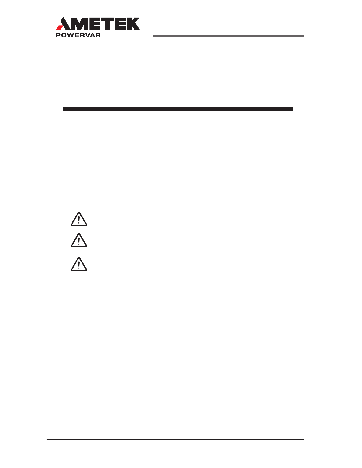
Danger- The danger symbol is used to indicate
imminently hazardous situations, locations, and
conditions which, if not avoided, WILL result in death,
serious injury, and/or severe property damage.
Caution- The caution symbol is used to indicate potentially hazardous situations and
conditions which, if not avoided, may result in
injury. Equipment damage may also occur.
Warning- The warning symbol is used to indicate
potentially hazardous situations and conditions which,
if not avoided, COULD result in serious injury or
death. Severe property damage COULD also occur.
Attention- The attention warning symbol is used to
indicate situations and conditions that can cause
operator injury and/or equipment damage.
Other warning symbols may appear along with the
Danger and Caution symbol and are used to specify
special hazards. These warnings describe particular areas where special care and/or procedures are required
in order to prevent serious injury and possible death.
Electrical warnings- The electrical warning symbol is a
lightning bolt mark enclosed in a triangle. The electrical
warning symbol is used to indicate high voltage locations and conditions may cause serious injury or death.
Explosion warnings- The explosion warning
symbol is an explosion mark enclosed in a triangle. The explosion warning symbol is used to
indicate locations and conditions where molten,
exploding parts may cause serious injury or death
if the proper precautions are not observed.
DANGER
CAUTION
WARNING
ATTENTION

5
A01-00071 Rev F www.powervar.com
Alternating Current
Refer to instruction manual/booklet.
Two person lift.

6
A01-00071 Rev Fwww.powervar.com
1.0 INTRODUCTION
Thank you for your purchase of the AMETEK Powervar Security II Series
Rackmount UPM ( hereafter referred to as “UPM”). AMETEK Powervar man-
ufactures two versions of the UPM – a standard version, and a medical version listed to UL60601-1 and cUL C22.2 No. 60601.1. In addition, all models
are compatible with International electrical distribution systems. International
versions are UL listed (Medical listed to IEC60601-1 and EN60601) and car-
ry the CE Mark. We’ve prepared this document to help familiarize you with
the functions and controls of this product. If, after reviewing this manual, you
have any questions at all, please feel free to contact our technical support
team by phone (1-800-369-7179) or email us at service.powervar@ametek.
com.
AMETEK Powervar is a global provider of power management solutions,
headquartered in Waukegan, Illinois, with international sales and distribution
ofces in Swindon, United Kingdom, Toronto, Canada, Mexico City, Mexico
and Germany. All AMETEK Powervar solutions incorporate a high energy
surge diverter, a noise lter and a low impedance isolation transformer.
Together these components prevent power disturbances from destroying,
degrading or disrupting system operations.
Registering you AMETEK Powervar Product
Please take a few moments to register your product purchase. Registration
is easy and quick via the product registration page found on our website at
www.powervar.com.
7
A01-00071 Rev F www.powervar.com
General
The AMETEK-Powervar Security II UPM (hereafter refered to as “UPM”)
systems are the most advanced, line interactive, true sinewave UPS products available for your application. Each model is designed to provide total
protection for your system from a complete range of power quality problems.
UPM systems will protect your installation from normal mode voltage impulses, electrical noise, sags, surges, brownouts, and blackouts. Each UPM
contains a low impedance isolation transformer, it completely eliminates
common-mode (neutral-to-ground) voltages that are a constant threat to
the reliable operation of microprocessor-based systems. When AC power is
present, UPM constantly lters and conditions the power supply. When AC
power fails, the UPM uses its internal, maintenance-free battery to supply
reserved power to your computer system. Regardless of whether or not
commercial power is present, the UPM is consistently on the job. Ensuring a
fully conditioned, safely managed interface between your computer system
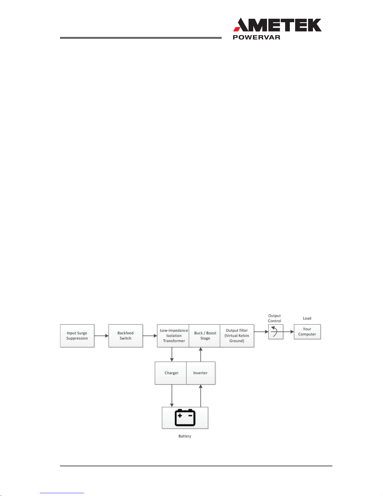
and its electrical power supply. Figure 1 illustrates the basic operation of the
UPM.
Figure 1
8
A01-00071 Rev Fwww.powervar.com
2.0 SAFETY INSTRUCTIONS
IMPORTANT - SAVE THESE INSTRUCTIONS
THIS MANUAL CONTAINS IMPORTANT SAFETY INSTRUCTIONS.
KEEP THIS MANUAL HANDY FOR REFERENCE.
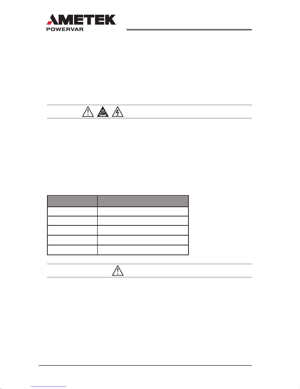
CAUTION
A battery can present a risk of electrical shock. Short-circuit currents can
be extremely high and can create severe burns as well as the risk of re or
explosion from vented gases. Always observe proper precautions.
When replacing batteries, use the same quantity, rating and type of batteries used by AMETEK Powervar. The batteries used in this UPM are sealed
lead-acid and are maintenance free. Proper disposal of batteries is required.
Refer to your local codes for disposal of batteries.
UPM Rating Quantity and Battery Rating
700 VA 4 X 23W @ 12 VOLT
1000 VA 4 X 23W @ 12 VOLT
1440 VA 4 X 23W @ 12 VOLT
2200 VA 8 X 23W @ 12 VOLT
3000 VA 8 X 23W @ 12 VOLT
CAUTION
• This UPM contains voltages which are potentially hazardous. All re-
pairs should be performed by qualied service personnel.
• To reduce the risk of re, connect only to a circuit provided with 20 am-
peres maximum branch circuit over-current protection in accordance
with the National Electric Code, ANSI/NFPA 70.
• The UPM has its own internal energy source (battery). The output receptacles of the UPM may be live even when the UPM is not connected to an AC Supply.

9
A01-00071 Rev F www.powervar.com
STATEMENT OF INTENDED USE
The medical UPMs are intended to protect medical, non-medical computer
equipment and medical devices that need battery backup, surge protection,
voltage regulation and line noise ltering in and around patient care areas.
Safe and continuous operation of the UPM depends partially on the care taken by users. Please observe the following precautions. Not following these
could result in warranty being voided.
NOTE:
• The UPM is intended for stationary use.
• UPM is not intended for patient contact or for installation that will cause
accidental contact of patients.
• Do not use this UPM for life support applications in which a malfunction
or failure of the UPM system could cause failure or signicantly alter
the performance of a life-support device.
• Do not use this UPM near or around ammable gases. Do not use this
UPM within oxygen-enriched atmospheres.
• Do not disassemble the UPM.
• UPM is CLASS 1 equipment.
• Do not attempt to power the UPM from any receptacle except a properly grounded receptacle that matches the input plug provided with the
UPM.
• Do not place the UPM near water or in environments of excessive
humidity.
• Do not allow liquid or any foreign object to get inside the UPM.
• Do not block air vents on the front of the UPM.
• Do not plug appliances such as hair dryers, fans, heaters, etc. into the
UPM.
• Do not place the UPM under direct sunshine or close to heat emitting
sources (excessively warm temperatures will shorten battery life).
• This UPM is intended for installation in a temperature controlled, indoor
area free of conductive contaminants.
• The AC power source for the UPM should be conveniently near the
UPM and easily accessible – avoid extension cords or temporary power strips to power the UPM.

10
A01-00071 Rev Fwww.powervar.com
• The total leakage current of the UPM and consumer connected equipment should not exceed 3.5 mA for non-medical units.
• Not for use in a computer room as dened in the Standard for the
Protection of Electronic Computer/Data Processing Equipment, ANSI/
NFPA 75.
• The socket-outlet shall be installed near the equipment and shall be
easily accessible.
• The battery should be disconnected from the UPM by unplugging at its
quick connectors when maintenance or service work inside the UPM is
necessary.
• Do not dispose of batteries in a re – batteries may explode.
• Do not open or mutilate batteries. Doing so may release electrolyte or
other toxic substances, which may be harmful to the skin, eyes, or the
environment.
A battery can present a risk of electric shock and high short circuit current.
The following precautions should be observed when working with batteries:
• Remove watches, rings, or any other metal jewelry or objects which
may make contact with the battery.
• Use tools with insulated handles.
Unit is suitable for IT applications.

11
A01-00071 Rev F www.powervar.com
FCC ISSUES
Attention
This UPM has been tested and found to comply with the limits for a Class A
digital devices (Class B compliance optional), pursuant to Part 15 of the FCC
rules. These limits are designed to provide reasonable protection against
harmful interference in both residential and commercial environments.
This equipment generates, uses and can radiate radio frequency energy
and if not installed and used in accordance with the instructions, may cause
harmful interference to radio communications. However, there is no guarantee that interference will not occur in a particular installation. If this equipment
does cause harmful interference to radio and/or television reception, which
can be determined by turning the UPM equipment on and off, the user is
encouraged to try to correct the interference by one or more of the following
measures:
Relocate the UPM
Relocate the load.
This device complies to Part 15 of the FCC Rules. Operation is subject to the
following two conditions: (1) this device may not cause harmful interference
and (2) this device must accept interference received, including interference
that may cause undesired operation.
12
A01-00071 Rev Fwww.powervar.com
3.0 INSTALLATION
Some units may require 2 people to lift.
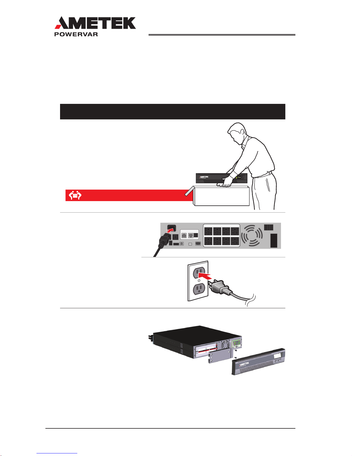
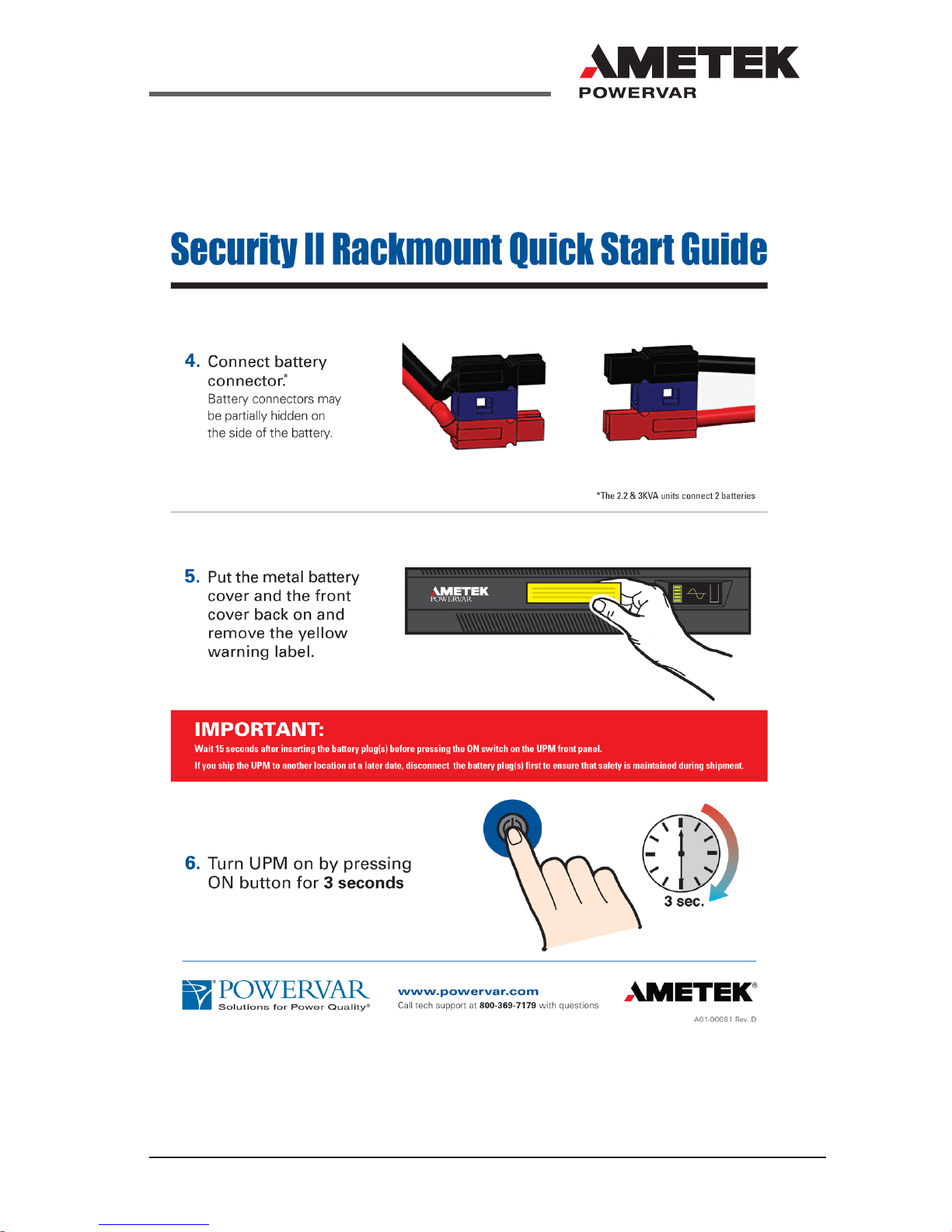
Security II Rackmount Quick Start Guide
This unit is shipped with the internal batteries disconnected.
Before starting the UPM, please follow these battery connection instructions.
1. Remove UPM from the box
2. Attached included
outlet cord and plug
UPM into wall.
Continued on side 2
3. Remove the UPM
front plastic cover and
metal battery cover
by removing the screws.
13
A01-00071 Rev F www.powervar.com

14
A01-00071 Rev Fwww.powervar.com
UNPACKING THE UPM
CAUTION
• Unpacking the unit in a low-temperature environment may cause
condensation to occur in and on the unit. Do not install the unit until
the inside and outside of the unit are absolutely dry {hazard of electric
shock}.
• The unit is heavy. Use caution when unpacking and moving the unit.
Use care when moving and opening the carton. Leave the components packaged until ready to install.
To unpack the unit and accessories:
1. Open the outer carton and remove the accessories packaged with
the unit.
2. Carefully lift the unit out of the outer carton.
3. Store the carton for future use.
Place the unit in a protected area that has adequate airow and is free of
humidity, ammable gas and corrosion.
NOTE:
Before installation, please read and understand the following
instructions. Carefully examine the carton for damage. Notify the
carrier immediately if damage is observed. Be sure to save the carton
should you ever need to ship the UPM for repair or maintenance.
This UPM is intended for indoor use only. Although your
UPM is very rugged, its internal components are not sealed
from the environment. The UPM must be installed in a
protected environment away from heat producing appliances such as furnaces, radiators, and heaters. Protect the
UPM from exposure to dripping or standing water and high
humidity or condensing air conditions.
15
A01-00071 Rev F www.powervar.com
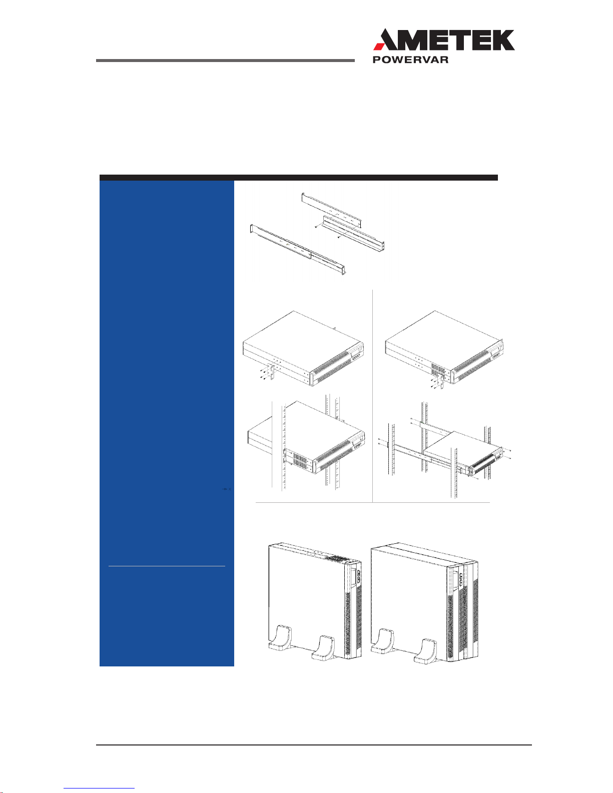
Rackmount Installation Guide
** Example of 4U unit* Example of a 2U unit
1. Assemble the side rails and
secure each with (2) screws.
DO NOT TIGHTEN.
2. Attach front of the rails to
front of rack with (1) fastener
for each side in the upper
mounting hole.
3. Attach rear of rails to rear of
rack with the (2) fasteners for
each side.
4. Tighten the (2) screws used to
assemble each rail in step 1.
5. For 2U
*
UPMs and battery
cabinets, attach (1) angled
mounting bracket to each side
of the UPM and/or each side
of the battery cabinet using
the (8) screws provided.
6. For 4U
**
UPMs - attach (2)
angled mounting brackets to
each side of the UPM using
the (16) screws provided.
7. Lift the battery cabinets and
UPM onto the mounting rails
and slide each into position.
8. Secure the 2U UPM and
battery cabinet with (4)
fasteners and the 4U UPMs
with (8) fasteners provided.
Rackmount UPM and the
external battery cabinet are
designed to be floor standing as
an alternative to rack mounting.
The UPM and external battery
cabinets use identical mounting
hardware and the procedure for
mounting is the same for both.
Each unit and each battery
cabinet must be mounted
to their own rail kits that
are included.
Floor Standing Installtion
Middle Rack Installation Standard Rack Installation
16
A01-00071 Rev Fwww.powervar.com
Rackmount Installation Guide
INSPECTING THE UPM
If any equipment has been damaged during shipment, keep the shipping cartons and packing materials
for the carrier or place of purchase and file a claim for shipping damage:
1. File with the carrier within 15 days of receipt of the equipment;
2. Send a copy of the damage claim within 15 days to your service representative.
WARNINGS
Use all supplied mounting hardware on each UPM and External Battery Cabinet.
NEVER depend on devices installed on lower levels to support other devices.
Two people are recommended for safe installation.
Never attempt to mount the UPM or external battery cabinet with the from mount ears
only. Continuous support is required throughout the mounting procedure to prevent
damage or injury.
17
A01-00071 Rev F www.powervar.com
4.0 OPERATION
NOTE:
In order to operate the UPM, you must rst plug the battery enable
plug(s) into the battery enable socket(s) behind the front panel of the
UPM.
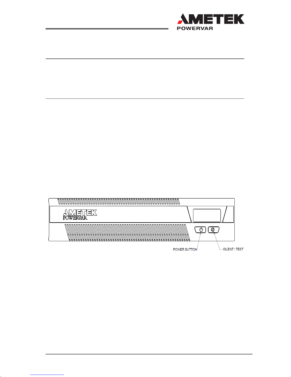
On/Off Button
The On/Off button is a dual function control:
• When the UPM is off and AC power is present to the UPM input,
pressing the On/Off button for more than 2 seconds will turn the UPM
output on.
• If battery is connected, pressing the On/Off switch for 2 seconds or
more will “cold-start” the UPM on its internal battery with no incoming
AC present.
• When the UPM is on, pressing the On/Off button for more than 2
seconds will turn off the UPM output power.
Test/Silence Button
The Test/Silence button is a dual function control:
• Pressing the Test/Silence button when AC power is present and the
UPM is operating causes the UPM to enter a self test mode in which
it tests both battery and inverter for a few seconds before returning to
the AC supply. We recommend you close all open les before initiating
self-test.
• When AC power fails, the UPM warns you with an audible alarm. The
Test/Silence button is used to silence the alarm. When battery power
begins to run low, the audible alarm will automatically return and beep
at a faster rate.

18
A01-00071 Rev Fwww.powervar.com
Load Monitor
The Load Monitor is a six-segment LED display that shows the current load
percentage. The rst 5 LED’s each indicate approximately 20% load, with the
6th red LED showing the UPM is overloaded.
Battery Charge Monitor
The Battery Charge Monitor is a ve-segment LED display that shows the
charge capacity of the internal battery from zero to 100%. Each LED indicates
approximately 20% of full charge.
Site Wiring Fault Indicator – (120 VAC models only)
The “SF” symbol will be displayed on the front panel of the UPM if it is
connected to an improperly wired AC receptacle. This is to indicate a missing
safety ground wire or a reversal in phase and neutral wiring. If the “SF”
is displayed on the front panel you should contact a qualied electrician
immediately.
NOTE:
Do not operate the UPM if the Site Wiring Fault LED is illuminated.
When lit, the LED is indicating a wiring condition, which may represent
a hazard of re or electrocution. In addition, improper wiring may create
reliability problems for both the UPM and the connected system. Never
use a 3-blade to 2-blade adapter (often called a “cheater”) to power UPM.
These devices remove the safety ground connection to the UPM and will
cause the Site Wiring Fault LED to illuminate.
19
A01-00071 Rev F www.powervar.com
Display Functionality
The location should provide adequate airflow around the UPM. Provide a minimum 3” clearance on all sides for proper ventilation.
Applying Power to the UPM
Connect the power cord to a verified grounded 3 wire receptacle. Verify
that the Site Wiring Fault “SF” is off (120 VAC models only). Once properly
connected and initially checked, turn on the UPM by pressing and holding the
front panel On/Off switch for 3 seconds.
Operational Tests
Observe the front panel of the UPM. The following table shows system status
behavior.
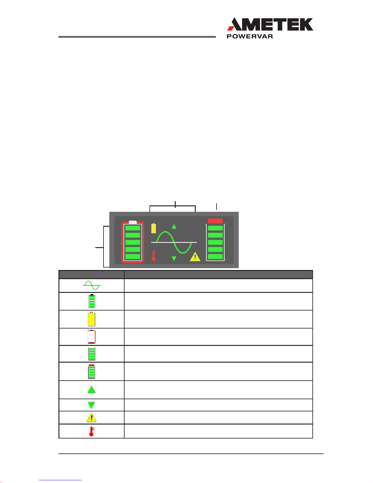
UPM LED DISPLAY UNIT STATUS
UPM output on
Battery charge status in 20% increments
UPM in battery operation due to improper incoming AC voltage
Battery fault or battery disconnected
UPM load status in 20% increments
UPM overloaded
Unit in buck operation due to high incoming AC voltage
Unit in boost operation due to low incoming AC voltage
Fault
UPM over temperature
UPM Front Panel
Output
Battery
System Status
20
A01-00071 Rev Fwww.powervar.com
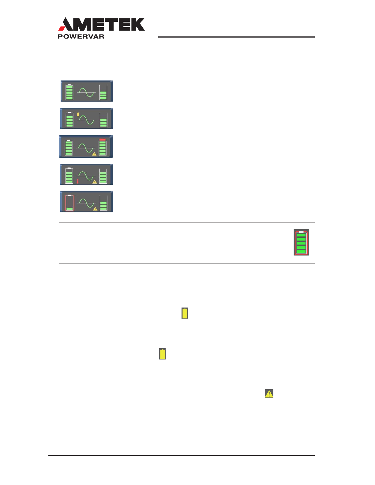
UPM Load and Battery Indicators
Example:
UPM display showing normal operation
(Fully charged batteries with 60% load shown)
UPM display showing in battery backup operation
(Batteries 80% charged with 60% load shown)
UPM display showing an overload condition (Batteries 100%
charged and greater than 100% load shown)
UPM display showing over-temperature condition
(Batteries 80% charged with 80% load shown)
UPM display showing a bad battery condition
(Inspect or replace battery unit loaded to 60%)
NOTE:
Depending on the charge state of the battery, it is possible that the
battery charge level LEDs may be ashing (this is normal).
Initial Startup
With the connected equipment powered off, perform an initial test of the
UPM backup function by pressing the Test/Silence button on the front pan-
el. During this test, the Battery LED ( ) on the front panel should briey
illuminate. It is also possible to test the backup function by unplugging the
UPM input power cord. If you choose to test the UPM in this manner, you
will note that the UPM will beep every few seconds while the power cord is
unplugged. The Battery LED ( ) will also illuminate constantly.
Once you have performed an initial test of the UPM backup function, turn on
the connected computer equipment. Verify that the unit is not overloaded. If
the unit is overloaded all load LED’s will be on the fault LED ( ) will ash,
remove the least critical devices from the UPM one by one until the overload
LED is extinguished. With the connected loads powered up, perform the
backup test once again by pressing the Test/Silence button or unplugging the
UPM. When this nal test is completed, the UPM will be ready to use.
 Loading...