

Powervar ABCDEF2000-11, ABCDEF3000-22, ABCDEF2000-22, ABCDEF3000-11, ABCDEF4000-22 User Instruction Manual
...Page 1
0-56r
POWERVAR Security Plus UPS
SSeeccuurriittyy PPlluus
s
OOnnLLiinnee UUnniinntteerrrruuppttiibbllee PPoowweerr SSuuppppllyy
UUsseerr IInnssttrruuccttiio
GENERAL SAFETY INSTRUCTIONS
Warnings in this manual appear in any of four ways:
onn MMaannuuaall
1
Page 2
DANGER
jury
CAUTION
POWERVAR Security Plus UPS
Danger- The danger symbol is a lightning bolt mark enclosed in a triangle
which precedes the 3/16-inch high letters spelling the word “DANGER”. The
danger symbol is used to indicate imminently hazardous situations, locations,
and conditions which, if not avoided, WILL result in death, serious injury,
and/or severe property damage.
Caution- The caution symbol is an exclamation mark enclosed in a triangle
which precedes the 3/16-inch high letters spelling the word “CAUTION”. The
caution symbol is used to indicate potentially hazardous situations and
conditions which, if not avoided may result in injury. Equipment damage may
also occur.
Warning- The warning symbol is an exclamation mark in a triangle which
precedes the 3/16-inch high letters spelling the word “WARNING”. The
warning symbol is used to indicate potentially hazardous situations and
conditions which, if not avoided COULD result in serious injury or death.
Severe property damage COULD also occur.
WARNING
Attention warnings- The attention warning symbol is an exclamation mark
enclosed in a triangle which precedes the 3/16-inch high letters spelling the
word “ATTENTION”. The Attention warning symbol is used to indicate
situations and conditions that can cause operator injury and/or equipment
damage.
ATTENTION
Other warning symbols may appear along with the Danger and
Caution symbol and are used to specify special hazards. These
warnings describe particular areas where special care and/or
procedures are required in order to prevent serious injury and
possible death:
Electrical warnings- The electrical warning symbol is a lightning bolt mark
enclosed in a triangle. The Electrical warning symbol is used to indicate high
voltage locations and conditions may cause serious injury or death if the
proper p
Explosion warnings- The explosion warning symbol is an explosion mark
enclosed in a triangle. The Explosion warning symbol is used to indicate
locations and conditions where molten, exploding parts may cause serious
in
or death if the proper precautions are not observed
2
Page 3

N
POWERVAR Security Plus UPS
Protective earth (Ground)
Connection point for the neutral conductor on PERMANENTLY INSTALLED
EQUIPMENT
Earth Ground
3
Page 4

POWERVAR Security Plus UPS
p
NNOOTTEE TTOO UUSSEERRSS
To ensure correct operation of the UPS, please read this instruction manu a l carefully. Please
keep this manual handy for future reference.
1. Before operating the UPS or connecting any load equipment, please ensure the UPS is
connected to a properly grounded electrical supply.
This UPS has dangerously high voltages on both its Input
and output connections. Contact with these voltages may
be life threatening. Please follow the operating instructions
carefully. Please give close attention to the warnings in this
manual and those posted on the UPS. There are no user
serviceable parts inside the UPS. Disassembly and/or
maintenance should only be done by an authorized
rofessional service technician.
IIMMPPOORRTTAANNTT IINNFFOORRMMAATTIIOONN FFOORR UUSSEERRSS OOFF
TTHHIISS UUNNIINNTTEERRRRUUPPT
TIIBBLLEE PPOOWWEERR SSUUPPPPLLYY
2. This UPS has dangerously high voltages on both its input and output connections.
Contact with these voltages may be life threatening.
3. Please do not disassemble the covers. There is a risk of electric shock.
4. In an emergency, immediately turn off the circuit breaker for the circuit supplying
power to the UPS. Also immediately turn off the battery circuit breaker.
5. This UPS has two power sources. One is the circuit supplying the UPS with input
power. The other is the UPS battery. Prior to any maintenance, both of these power
sources must be disconnected to ensure that the UPS is de-energized. If only the input
power is disconnected, the UPS can still operate from the battery, and hazardous
voltages may still exist.
6. To prevent damage or a safety hazard, keep the UPS away from open flame and any
other devices that may cause sparks.
7. Do not open or damage individual battery cases as spillage of caustic electrolyte may
occur resulting in danger to life, safety, and the environment.
8. The charging characteristics of UPS batteries vary by both brand and type. For this
reason, replacement batteries should be of the same brand and type as those specified
by the manufacturer. Using batteries other than the brand and type specified by the
manufacturer may affect the performance of the UPS. Before installing batteries of
different brand or type, please consult with the manufacturer.
9. The UPS has an internal EMI filter for purposes of enhancing electromagnetic
compatibility with the input mains supply. This filter produc es leakage current to earth
on the input mains. When selecting a circuit breaker for the branch circuit supplying
power to the UPS, ensure that the breaker selected is not an ELCB type circuit breaker
that detects earth leakage current.
10. Please contact the manufacturer or an authorized distributor for any assistance with
troubleshooting.
4
Page 5

POWERVAR Security Plus UPS
11. The UPS should only be serviced or maintained by a factory authorized service
technician.
12. This UPS meets FCC Class A electromagnetic compatibility requirements.
13. Depleted batteries must be disposed of in a proper manner. Contact your local
recycling or hazardous waste center or the UPS manufacturer for instructions
concerning proper disposal.
5
Page 6

POWERVAR Security Plus UPS
CCOONNTTEENNTTSS
1.0 Overview
2.0 Structure and Basic Principles
3.0 Equipment Installation
4.0 Equipment Use and Maintenance
5.0 Battery Tray Replacement
5.1.1 Battery Tray Replacement (2-6kVA) .................................... 53
5.1.2 Battery Tray Replacement (2-6kVA) .................................... 54
5.1.3 Battery Tray Replacement (8-15kVA) .................................. 55
6.0 Packing, Transportation and Storage
7.0 Mechanical Characteristics
7.1 Unit Dimensions/Weights .................................................... 57
7.2 Shipping Dimensions/Weights .............................................. 57
8.0 Warranty
1.1 Primary Functions and Operating Characteristics .......................... 7
1.2 Precautions ............................................................................ 7
1.3 Performance Specifications ....................................................... 8
2.1 General Structure .................................................................... 30
2.1.1 Security Plus Front Panel and Rear Panel Structure ................... 30
2.1.2 Security Plus Display/Controls Operation ................................. 31
2.1.3 Security Plus Terminal Connection Block Illustration (2-6kVA) ..... 35
2.1.4 Security Plus Terminal Connection Block Illustration (8-15kVA) ... 38
2.1.5 RS232 Communications ......................................................... 41
2.1.6 Communication Port Maintenance.. ..................................... .41
2.2 Basic Principles ....................................................................... 41
3.1 Site and Environment Requirements .......................................... 43
3.1.1 Site Requirements ................................................................ 43
3.1.2 Environment Requirements .................................................... 43
3.2 Procedures of Dismantling Containers ........................................ 43
3.3 Installation of UPS ................................................................... 46
4.1 Preparations for Start-up .......................................................... 47
4.2 Routine UPS Start-up Sequence ................................................ 47
4.3 Routine UPS Shutdown ............................................................ 47
4.4 Important Battery Issues ......................................................... 47
4.5 Frequent Trouble Causes .......................................................... 48
4.6 Troubleshooting ...................................................................... 50
4.6.1 Overview ............................................................................ 50
4.6.2 Troubleshooting Steps ........................................................... 50
5.1 Precautions ............................................................................ 52
6.1 Packing.................................................................................. 56
6.2 Transportation ........................................................................ 56
6.3 Storage ................................................................................. 56
6.4 Fuse Replacements .................................................................. 56
8.1 Basic Warranty ....................................................................... 58
8.2 Limitations ............................................................................. 58
6
Page 7

POWERVAR Security Plus UPS
11..00 OOvveerrvviieew
The Security Plus UPS is a high frequency, double conversion (true online) intelligent UPS for
use with file servers, enterprise servers, microcomputers, telecommunication systems, data
centers, laboratory instrumentation, and other microprocessor-based equipment that requires
high quality, conditioned uninterruptible power. It is designed for use in telecom, IT, LAN,
banking and financial, or almost any application where the performance of computer systems is
mission critical. The Security Plus UPS is designed for connection to a single-phase alternating
current input and provides power output loads requiring single- phase alternating current power.
1.1 Primary Functions and Operating Characteristics
1. Intelligent RS232 communication - Using the available RS232 standard data interface or
USB port and UPS power management software, you take advantage of three
communications functions: (1) The connected host computer can supervise UPS
operation and control electric parameters, (2) Remote control of power ON and OFF
functions can be accomplished, (3) with an available internal SNMP network adapter
inserted in the internal card SNMP option card slot, the UPS is discoverable by a
network.
2. High input power factor and low input THDI – This UPS uses an advanced active power
factor correction (PFC) technology, which improves the input power factor and makes
the UPS friendlier to the input mains supply .
w
3. High performance to price ratio – This UPS uses high frequency pulse width modulation
(PWM) technology to ensure high efficiency, reduced size and weight, and improved
operational reliability.
4. Dependable self-protection functions – This UPS provides dependable self-protection
functions such as output over-voltage protection, battery low voltage protection, and
input over-voltage protection. These self-protection features improve reliability and
adaptability to a variety of electronic applications and installation environments.
5. Wide input voltage window – This UPS has a wide input voltage operating window, which
ensures that even in the presence of unusually low or high input voltage, the UPS will
continue to supply high quality dependable power to the connected load without
discharging its battery. This reduces battery discharge cycles and results in increased
battery life.
1.2 Precautions
Please be careful to observe the following general safety precautions
during operation or maintenance
1. There are no user serviceable parts inside this UPS. Please don't remove the covers. This
system can only be maintained or repaired by trained authorized service technicians.
2. To improve electromagnetic compatibility (EMC), this UPS has an input EMI filter, which
produces potentially dangerous leakage current to ground. Ensure the UPS is connected
to a properly grounded input electrical source.
7
Page 8

POWERVAR Security Plus UPS
3. Install this UPS indoors in an environment that is temperature and humidity controlled.
4. Install this UPS in a dust-free environment.
5. This UPS has two sources of power. Before maintenance is performed, turn off the
branch circuit breaker powering the UPS and turn off all battery switches.
6. Even with the AC input power supply turned off, the UPS’s internal battery still
represents a potentially dangerous source of high voltage electrical power.
7. If the battery circuit has not been disconnected from the AC input, dangerous voltage
potential still exists between the battery terminal and the ground terminal.
8. UPS batteries represent a high voltage source and a potential hazard to personal safety.
Please pay attention to proper safety precautions and use insulated tools during
installation.
9. UPS batteries contain corrosive and caustic chemicals. Improper handling of batteries
may lead to the unintended release or leakage of these substances. Please handle
batteries carefully.
10. Condensation may occur when the UPS is moved from a low temperature, low humidity
environment to a warm humid environment. Condensation may cause UPS damage or
hazardous electrical shock. To ensure the safety of both the UPS and the personnel
around it, make sure that the UPS is installed only af ter it has fully acclimated to its
installation environment. This UPS is not intended to be operated in an environment of
either low temperature or high humidity.
11. DC vo ltage is still present on the battery fuses even with the UPS turned off. The battery
trays must be removed before servicing UPS.
1.3 Performance Specifications
The major specifications of the Security Plus UPS are shown in the individual specification
sheets on the following pages.
Note: Specifications are subject to change without notice.
8
Page 9
POWERVAR Security Plus UPS
A
A
(
(
)
(
)
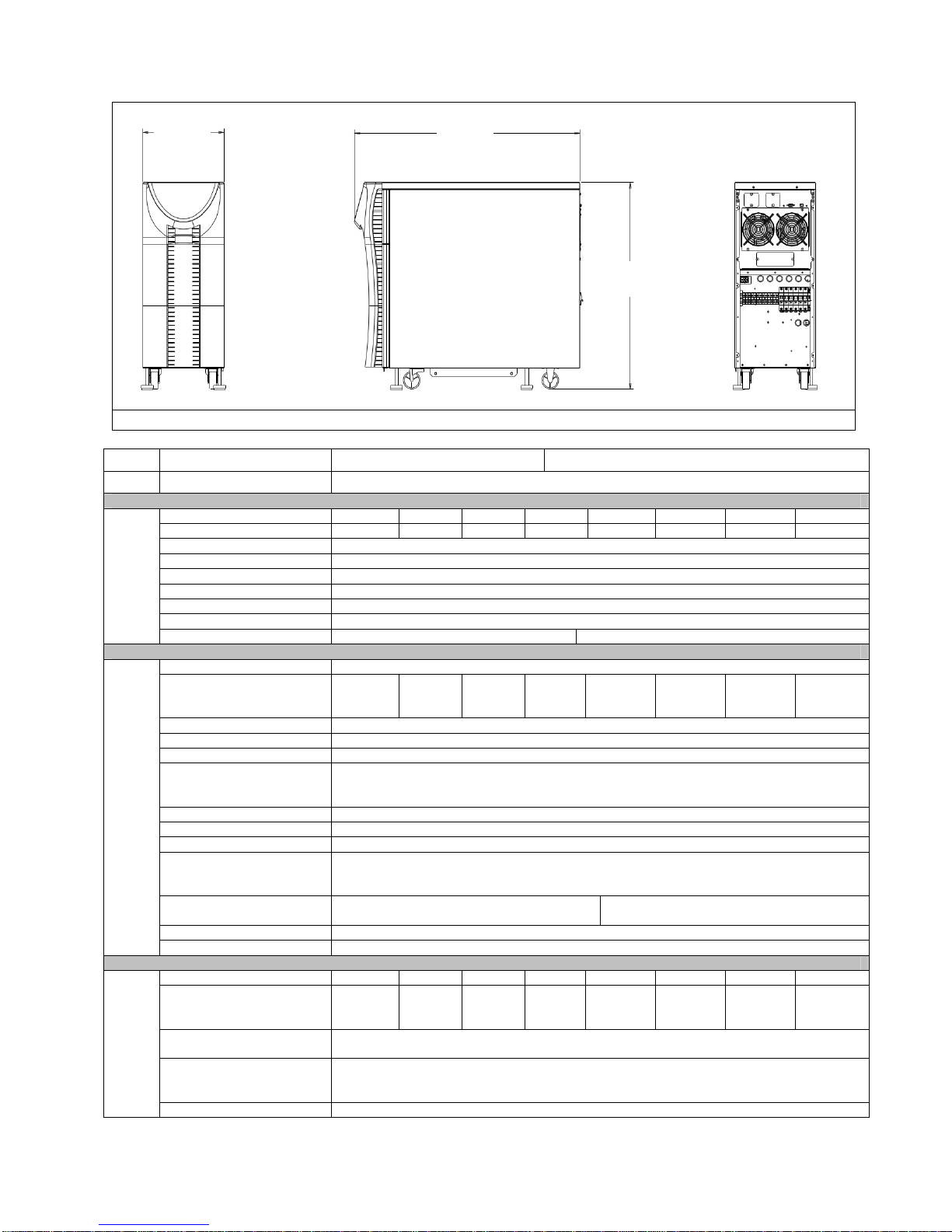
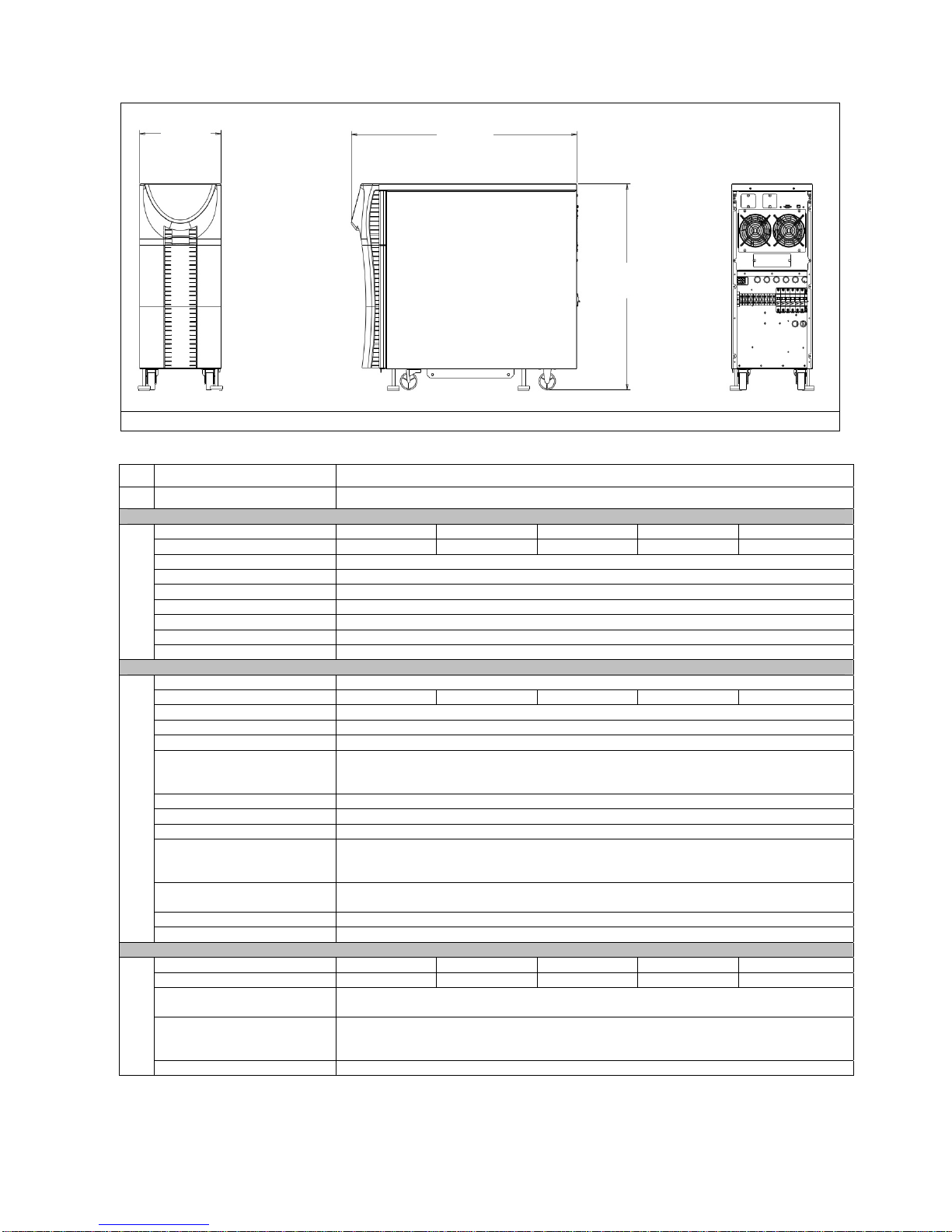
11.80
299.72)
32.65
829.4
28.70
729.0
FRONT SIDE REAR
Model
BCDEF2000-11
BCDEF2000-22
Topology True On line, Double-Conversion, IGBT Design, Internal Isolation Transformer
Voltage (VAC) 100 115 120 200 208 220 230 240
Voltage Range (VAC) 70-115 81-132 84-138 140-230 146-239 154-253 161-264 168-276
Voltage Tolerance + 15% ~ -30% before switching to batteries
Frequency (Hz) 50/60
Frequency Tolerance 42 Hz to 69 Hz before switching to batteries
INPUT
Input PF > 0.95
Input Current THD < 5.0%
Input Connection Hardwired Standard; Line Cord Optional (Consult factory)
Input Capacity 2160 VA 2160 VA
Capacity 2000VA/ 1800W
Voltage (VAC) 100 115 120 200 120
220 230 120
208
240
Voltage Regulation ± 3.0% Max, ± 1.0% Normal
Output Voltage THD < 3.0%
Power Factor 0.9
Step Load Response ± 4.0% for 50% step load change
± 6.0% for 100% step load change
Return to ± 3.0% of nominal within 3 cycles
Crest Factor 3:1
OUTPUT
Frequency (Hz) 50/60
Frequency Regulation ± 0.1Hz
Overload 125% for 2 minutes
150% for 30 seconds
300% for 500ms
Efficiency AC-AC >85.0%
DC-AC >71.0%
AC-AC >85.0%
DC-AC >70.0%
Common Mode Noise < 0.5 VRMS
Output Connection Hardwired Standard; Output Receptacles Optional (Consult factory)
Input Voltage (VAC) 100 115 120 200 208 220 230 240
Output Voltage (VAC) 100 115 120 200 120
220 230 120
208
240
Transformer Voltage
± 3.0%
Regulation
BYPASS
Overload 125% for 10 minutes
150% for 500ms
1000% for 1 cycle
Efficiency > 95.0%
208
240
208
240
9
Page 10

BATTERY
ENVIRONMENT
AGENCIES
POWERVAR Security Plus UPS
Voltage (VDC) 96.0, nominal
109.2, float
Battery 12V, 34W flame retardant
High Rate, Sealed Lead-Acid
Quantity 8
Charge Current (ADC) 2.0
Backup Time (min) > 7.0
Recharge Time 8 hours to 90%
Temperature (°C) 0 to 40, operating
-20 to 60, transit
Altitude (m) 2,000, operating
12,000, transit
Humidity 5.0% to 90.0%, non condensing
Audible (dBA) 50-55 @ 1m from front of unit
Heat Dissipation (BTU/hr) 1084
EMC FCC Part 15J Class A
EN 55022 Class A/ CISPR 22
EN 50091-2
IEC 61000-3-2
Safety Agencies UL1778 4th Ed.
cUL to CSA22.2 No.107.1
CE (-22 only):
IEC62040, w/CB report and cert
IEC62040, w/CB report and cert
IEC61000-4-2, Electrostatic Discharge
IEC61000-4-3, Radiated Electromagnetic Field Immunity
IEC61000-4-4, Electrical Fast Transient/ Burst Immunity
IEC61000-4-5, Surge Immunity
IEC61000-4-6, Immunity to Conducted Radio Frequency Disturbances
IEC61000-4-8, Power Frequency Magnetic Field Immunity
IEC61000-4-11, Voltage Dips, Short Interruptions, and Voltage Variations
RoHS All units are RoHS compliant
Communication RS-232
USB
DB-9 Dry Contacts
Internal SNMP Adapter (option)
Unit Weight -11 Models 215 lbs. / 97 kg.
OTHER
Shipping Weight -11 Models 310 lbs. / 139 kg.
-22 Models 221 lbs. / 100 kg.
-22 Models 316 lbs. / 142 kg.
Plug & Receptacle* L5-30P (2)5-20R (1)L5-30R 208 VAC Input L6-30P (2)5-20R (1)L6-30R
240 VAC Input L6-20P (2)5-20R (1)L6-20R
*Hardwired unit is standard. Plug & Receptacle is optional. Contact factory for part numbers.
NOISE REJECTION-ISOLATION: With unit under power and an ANSI/IEEE C62.41Cat. A pulse applied either normal or common mode at the input, the
noise output voltage will be less than 10V normal mode and less than 0.5V common mode in all four quadrants (CM-NM, NM-NM, CM-CM, NM-CM).
SURGE VOLTAGE WITHSTAND CAPABILITY: Tested under power to ANSI/IEEE C62.41 Cat. A & B (formerly IEEE587-1980). Cat. A - 6000V @ 200
amps, 0.5 usec risetime, 100 kHZ decay, Cat. B - 6000V @ 500 amps, 0.5 usec risetime, 100 kHZ decay.
10
Page 11

POWERVAR Security Plus UPS
ABCDEF2000-11 Compatible External (Extended Run) Battery Cabinets:
Model: D9632-11 Description: 4 Pack (32 Batt) Extended Run Battery Cabinet
Model: D9648-11 Description: 6 Pack (48 Batt) Extended Run Battery Cabinet
25% (450 W) 50% (900 W) 75% (1350 W) 100% (1800 W)
Internal Batteries Only 20 13 10 7
Internal + 1) D9632-11 170 110 80 65
Internal + 2) D9632-11 375 250 190 140
Internal + 3) D9632-11 625 400 300 225
Internal + 4) D9632-11 >12 Hrs 575 400 300
Internal + 5) D9632-11 >12 Hrs >12 Hrs 575 450
Internal + 1) D9648-11 250 180 130 100
Internal + 2) D9648-11 625 400 300 230
Internal + 3) D9648-11 >12 Hrs 700 500 375
Internal + 4) D9648-11 >12 Hrs >12 Hrs >12 Hrs 575
Internal + 5) D9648-11 >12 Hrs >12 Hrs >12 Hrs >12 Hrs
Note: Run-Times are based on new fully charged batteries at 25 deg C ambient.
ABCDEF2000-22 Compatible External (Extended Run) Battery Cabinets:
Model: D9632-22 Description: 4 Pack (32 Batt) Extended Run Battery Cabinet
Model: D9648-22 Description: 6 Pack (48 Batt) Extended Run Battery Cabinet
25% (450 W) 50% (900 W) 75% (1350 W) 100% (1800 W)
Internal Batteries Only 18 12 9 7
Internal + 1) D9632-22 160 110 80 65
Internal + 2) D9632-22 325 230 180 140
Internal + 3) D9632-22 575 375 275 225
Internal + 4) D9632-22 >12 Hrs 575 425 325
Internal + 5) D9632-22 >12 Hrs >12 Hrs 550 425
Internal + 1) D9648-22 240 170 130 100
Internal + 2) D9648-22 575 375 275 225
Internal + 3) D9648-22 >12 Hrs 650 475 375
Internal + 4) D9648-22 >12 Hrs >12 Hrs >12 Hrs 550
Internal + 5) D9648-22 >12 Hrs >12 Hrs >12 Hrs >12 Hrs
Note: Run-Times are based on new fully charged batteries at 25 deg C ambient.
Battery Life Disclaimer: POWERVAR’s standard battery warranty applies only to UPS and UPM products which are continuously
connected to AC mains power, except during utility power outages. Products which are regularly and intentionally disconnected from AC
mains power will experience battery discharge/charge cycles potentially far more numerous than those for which the battery was
designed. As a result, products used in such applications will experience substantially reduced battery life. For that reason,
POWERVAR’s standard battery warranty does not apply for applications in which the UPS or UPM product is regularly and intentionally
disconnected from AC mains power. POWERVAR UPS and UPM products used in such applications shall receive a 90 day warranty on
batteries.
ABCDEF2000-11 TYPICAL RUN-TIMES (MINs)
ABCDEF2000-22 TYPICAL RUN-TIMES (MINs)
Warranty/Support: POWERVAR warrants the electronics and transformers used in its uninterruptible power supplies to be free from
defects in materials and workmanship for a period of three years from the date of shipment. Batteries are warranted for a period of two
years from the date of shipment for standby use; 90 days for cyclic use. For North American service or support on any POWERVAR
product, please contact POWERVAR Technical Support at (800) 369-7179 (in Illinois call (847-596-7000). For service and support in
EMEA, contact POWERVAR, Ltd. in the United Kingdom at +44 (0) 1793 553980. Or visit the POWERVAR website at
www.powervar.com.
POWERVAR, Inc. -
1450 Lakeside Drive, Waukegan, IL 60085
11
Page 12
POWERVAR Security Plus UPS
A
A
(
(
)
(
)
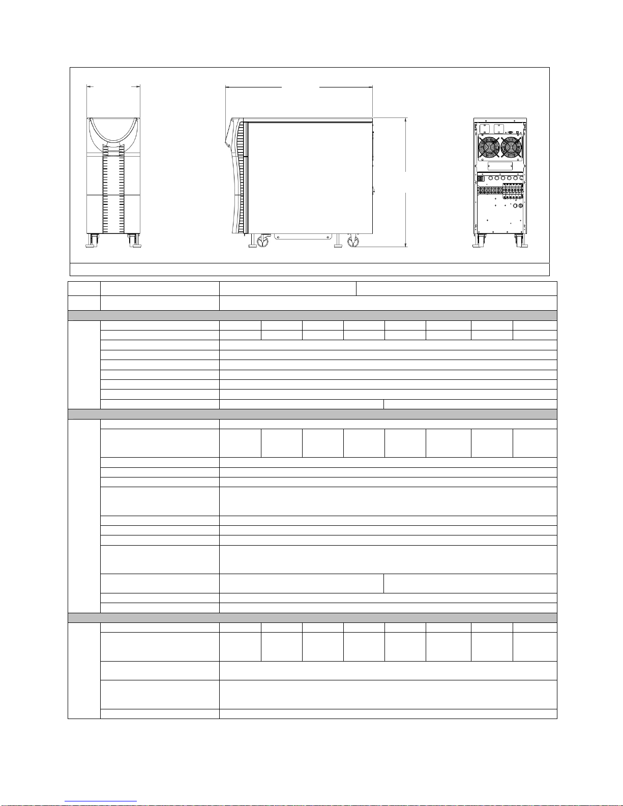
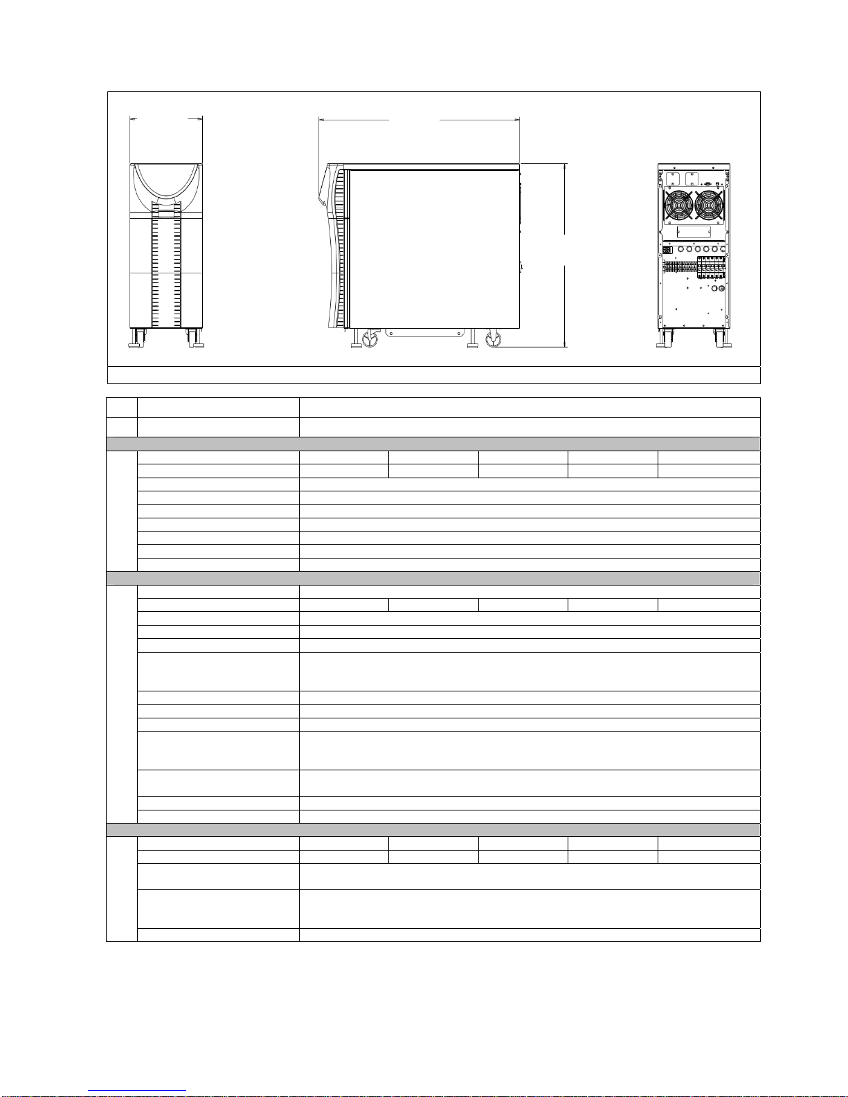
11.80
299.72)
FRONT SIDE REAR
\
Topology True On-line, Double-Conversion, IGBT Design, Internal Isolation Transformer
Model
BCDEF3000-11
Voltage (VAC) 100 115 120 200 208 220 230 240
Voltage Range (VAC) 70-115 81-132 84-138 140-230 146-239 154-253 161-264 168-276
Voltage Tolerance + 15% ~ -30% before switching to batteries
Frequency (Hz) 50/60
Frequency Tolerance 42 Hz to 69 Hz before switching to batteries
INPUT
Input PF > 0.95
Input Current THD < 5.0%
Input Connection Hardwired Standard; Line Cord Optional (Consult factory)
Input Capacity 3240 VA 3240 VA
Capacity 3000VA/ 2700W
Voltage (VAC) 100 115 120 200 120
Voltage Regulation ± 3.0% Max, ± 1.0% Normal
Output Voltage THD < 3.0%
Power Factor 0.9
Step Load Response ± 4.0% for 50% step load change
± 6.0% for 100% step load change
Return to ±3.0% of nominal within 3 cycles
Crest Factor 3:1
OUTPUT
Frequency (Hz) 50/60
Frequency Regulation ± 0.1Hz
Overload 125% for 2 minutes
150% for 30 seconds
300% for 500ms
Efficiency AC-AC >85.0%
DC-AC >77.0%
Common Mode Noise < 0.5 VRMS
Output Connection Hardwired Standard; Output Receptacles Optional (Consult factory)
Input Voltage (VAC) 100 115 120 200 208 220 230 240
Output Voltage (VAC) 100 115 120 200 120
Transformer Voltage
± 3.0%
Regulation
BYPASS
Overload 125% for 10 minutes
150% for 500ms
1000% for 1 cycle
Efficiency > 95.0%
32.65
829.4
28.70
729.0
BCDEF3000-22
208
240
AC-AC >85.0%
DC-AC >76.0%
208
240
220 230 120
220 230 120
208
240
208
240
12
Page 13

POWERVAR Security Plus UPS
*Hardwired unit is standard. Plug & Receptacle is optional. Contact factory for part numbers.
NOISE REJECTION-ISOLATION: With unit under power and an ANSI/IEEE C62.41Cat. A pulse applied either normal or common mode at the input, the
noise output voltage will be less than 10V normal mode and less than 0.5V common mode in all four quadrants (CM-NM, NM-NM, CM-CM, NM-CM).
SURGE VOLTAGE WITHSTAND CAPABILITY: Tested under power to ANSI/IEEE C62.41 Cat. A & B (formerly IEEE587-1980). Cat. A - 6000V @ 200
amps, 0.5 usec risetime, 100 kHZ decay, Cat. B - 6000V @ 500 amps, 0.5 usec risetime, 100 kHZ decay.
Voltage (VDC) 96.0, nominal
Battery 12V, 34W flame retardant
Quantity 16
Charge Current (ADC) 3.0
BATTERY
Backup Time (min) > 12.0
Recharge Time 8 Hours to 90%
Temperature (°C) 0 to 40, operating
Altitude (m) 2,000, operating
Humidity 5.0% to 90.0%, non condensing
Audible (dBA) 50-55 @ 1m from front of unit
Heat Dissipation (BTU/hr) 1626
ENVIRONMENT
EMC FCC Part 15J Class A
Safety Agencies UL1778 4th Ed.
AGENCIES
RoHS All units are RoHS compliant
Communication RS-232
Unit Weight -11 Models 294 lbs. / 132 kg.
OTHER
Shipping Weight -11 Models 389 lbs. / 175 kg.
Plug & Receptacle* L5-30P (2)5-20R (1)L5-30R 208 VAC Input L6-30P (2)5-20R (1)L6-30R
109.2, float
High Rate, Sealed Lead-Acid
-20 to 60, transit
12,000, transit
EN 55022 Class A/ CISPR 22
EN 50091-2
IEC 61000-3-2
cUL to CSA22.2 No.107.1
CE (-22 only):
IEC62040, w/CB report and cert
IEC61000-4-2, Electrostatic Discharge
IEC61000-4-3, Radiated Electromagnetic Field Immunity
IEC61000-4-4, Electrical Fast Transient/ Burst Immunity
IEC61000-4-5, Surge Immunity
IEC61000-4-6, Immunity to Conducted Radio Frequency Disturbances
IEC61000-4-8, Power Frequency Magnetic Field Immunity
IEC61000-4-11, Voltage Dips, Short Interruptions, and Voltage Variations
USB
DB-9 Dry Contacts
Internal SNMP Adapter (option)
-22 Models 300 lbs. / 135 kg.
-22 Models 395 lbs. / 178 kg.
240 VAC Input L6-20P (2)5-20R (1)L6-20R
13
Page 14

POWERVAR Security Plus UPS
ABCDEF3000-11 Compatible External (Extended Run) Battery Cabinets:
Model: D9632-11 Description: 4 Pack (32 Batt) Extended Run Battery Cabinet
Model: D9648-11 Description: 6 Pack (48 Batt) Extended Run Battery Cabinet
25% (675 W) 50% (1350 W) 75% (2025 W) 100% (2700 W)
Internal Batteries Only 40 24 17 12
Internal + 1) D9632-11 170 100 70 55
Internal + 2) D9632-11 325 200 140 110
Internal + 3) D9632-11 550 325 225 170
Internal + 4) D9632-11 >12 Hrs 450 310 230
Internal + 5) D9632-11 >12 Hrs 600 400 300
Internal + 1) D9648-11 250 150 100 80
Internal + 2) D9648-11 550 325 220 160
Internal + 3) D9648-11 >12 Hrs 525 350 250
Internal + 4) D9648-11 >12 Hrs >12 Hrs 525 375
Internal + 5) D9648-11 >12 Hrs >12 Hrs 700 525
Notes: Run-Times are based on new fully charged batteries at 25 deg C ambient.
ABCDEF3000-11 TYPICAL RUN-TIMES (MINs)
ABCDEF3000-22 Compatible External (Extended Run) Battery Cabinets:
Model: D9632-22 Description: 4 Pack (32 Batt) Extended Run Battery Cabinet
Model: D9648-22 Description: 6 Pack (48 Batt) Extended Run Battery Cabinet
25% (675 W) 50% (1350 W) 75% (2025 W) 100% (2700 W)
Internal Batteries Only 35 23 15 12
Internal + 1) D9632-22 160 100 70 55
Internal + 2) D9632-22 325 200 140 110
Internal + 3) D9632-22 500 300 210 165
Internal + 4) D9632-22 >12 Hrs 425 300 230
Internal + 5) D9632-22 >12 Hrs 575 400 300
Internal + 1) D9648-22 230 150 100 80
Internal + 2) D9648-22 500 300 210 160
Internal + 3) D9648-22 >12 Hrs 500 350 270
Internal + 4) D9648-22 >12 Hrs >12 Hrs 525 375
Internal + 5) D9648-22 >12 Hrs >12 Hrs 675 500
Notes: Run-Times are based on new fully charged batteries at 25 deg C ambient.
Battery Life Disclaimer: POWERVAR’s standard battery warranty applies only to UPS and UPM products which are continuously
connected to AC mains power, except during utility power outages. Products which are regularly and intentionally disconnected from AC
mains power will experience battery discharge/charge cycles potentially far more numerous than those for which the battery was
designed. As a result, products used in such applications will experience substantially reduced battery life. For that reason,
POWERVAR’s standard battery warranty does not apply for applications in which the UPS or UPM product is regularly and intentionally
disconnected from AC mains power. POWERVAR UPS and UPM products used in such applications shall receive a 90 day warranty on
batteries.
ABCDEF3000-22 TYPICAL RUN-TIMES (MINs)
Warranty/Support: POWERVAR warrants the electronics and transformers used in its uninterruptible power supplies to be free from
defects in materials and workmanship for a period of three years from the date of shipment. Batteries are warranted for a period of two
years from the date of shipment for standby use; 90 days for cyclic use. For North American service or support on any POWERVAR
product, please contact POWERVAR Technical Support at (800) 369-7179 (in Illinois call (847-596-7000). For service and support in
EMEA, contact POWERVAR, Ltd. in the United Kingdom at +44 (0) 1793 553980. Or visit the POWERVAR website at
www.powervar.com.
POWERVAR, Inc. -
1450 Lakeside Drive, Waukegan, IL 60085
14
Page 15
POWERVAR Security Plus UPS
A
(
(
)
(
)
11.80
299.7
32.65
829.4
28.70
729.0
FRONT SIDE REAR
Model
Topology True On-Line, Double-Conversation, IGBT Design, Internal Isolation Transformer
Voltage (VAC) 200 208 220 230 240
Voltage Range (VAC) 140-230 146-239 154-253 161-264 168-276
Voltage Tolerance + 15% ~ -30% before switching to batteries
Frequency (Hz) 50/60
Frequency Tolerance 42 Hz to 69 Hz before switching to batteries
INPUT
Input PF > 0.95
Input Current THD < 5.0%
Input Connection Hardwired Standard; Line Cord Optional (Consult factory)
Input Capacity 4320 VA
Capacity 4000VA/ 3600W
Voltage (VAC) 200 120/208/240 220 230 120/208/240
Voltage Regulation ± 3.0% Max, ± 1.0% Normal
Output Voltage THD < 3.0%
Power Factor 0.9
Step Load Response ± 4.0% for 50% step load change
Crest Factor 3:1
Frequency (Hz) 50/60
OUTPUT
Frequency Regulation ± 0.1Hz
Overload 125% for 2 minutes
Efficiency AC-AC >85.0%
Common Mode Noise < 0.5 VRMS
Output Connection Hardwired Standard; Output Receptacles Optional (Consult factory)
Input Voltage (VAC) 200 208 220 230 240
Output Voltage (VAC) 200 120/208/240 220 230 120/208/240
Transformer Voltage
Regulation
Overload 125% for 10 minutes
BYPASS
Efficiency > 95.0%
± 6.0% for 100% step load change
Return to ±3.0% of nominal within 3 cycles
150% for 30 seconds
300% for 500ms
DC-AC >78.0%
± 3.0%
150% for 500ms
1000% for 1 cycle
BCDEF4000-22
15
Page 16

BATTERY
ENVIRONMENT
AGENCIES
POWERVAR Security Plus UPS
Voltage (VDC) 96.0, nominal
109.2, float
Battery 12V, 34W flame retardant
High Rate, Sealed Lead-Acid
Quantity 16
Charge Current (ADC) 3.0
Backup Time (min) > 8.0
Recharge Time 8 Hours to 90%
Temperature (°C) 0 to 40, operating
-20 to 60, transit
Altitude (m) 2,000, operating
12,000, transit
Humidity 5.0% to 90.0%, non condensing
Audible (dBA) 50-55 @ 1m from front of unit
Heat Dissipation (BTU/hr) 3252
EMC FCC Part 15J Class A
EN 55022 Class A/ CISPR 22
EN 50091-2
IEC 61000-3-2
Safety Agencies UL1778 4th Ed.
cUL to CSA22.2 No.107.1
CE:
IEC62040, w/CB report and certificate
IEC61000-4-2, Electrostatic Discharge
IEC61000-4-3, Radiated Electromagnetic Field Immunity
IEC61000-4-4, Electrical Fast Transient/ Burst Immunity
IEC61000-4-5, Surge Immunity
IEC61000-4-6, Immunity to Conducted Radio Frequency Disturbances
IEC61000-4-8, Power Frequency Magnetic Field Immunity
IEC61000-4-11, Voltage Dips, Short Interruptions, and Voltage Variations
RoHS All units are RoHS compliant
Communication RS-232
USB
DB-9 Dry Contacts
Internal SNMP Adapter (option)
OTHER
Unit Weight 317 lbs. / 143 kg.
Shipping Weight 412 lbs. / 185 kg.
*Hardwire unit is standard. Plug & Receptacle is optional. Contact factory for part numbers.
NOISE REJECTION-ISOLATION: With unit under power and an ANSI/IEEE C62.41Cat. A pulse applied either normal or common mode at the input, the
noise output voltage will be less than 10V normal mode and less than 0.5V common mode in all four quadrants (CM-NM, NM-NM, CM-CM, NM-CM).
SURGE VOLTAGE WITHSTAND CAPABILITY: Tested under power to ANSI/IEEE C62.41 Cat. A & B (formerly IEEE587-1980). Cat. A - 6000V @ 200
amps, 0.5 usec risetime, 100 kHZ decay, Cat. B - 6000V @ 500 amps, 0.5 usec risetime, 100 kHZ decay.
Plug & Receptacle* L6-30P (2)5-20R (1)L6-30R
16
Page 17

POWERVAR Security Plus UPS
Compatible External (Extended Run) Battery Cabinets:
Model: D9632-22 Description: 4 Pack (32 Batt) Extended Run Battery Cabinet
Model: D9648-22 Description: 6 Pack (48 Batt) Extended Run Battery Cabinet
25% (900 W) 50% (1800 W) 75% (2700 W) 100% (3600 W)
Internal Batteries Only 25 17 11 8
Internal + 1) D9632-22 120 75 50 35
Internal + 2) D9632-22 250 150 100 75
Internal + 3) D9632-22 375 220 150 110
Internal + 4) D9632-22 550 325 210 160
Internal + 5) D9632-22 >12 Hrs 425 275 210
Internal + 1) D9648-22 170 110 75 55
Internal + 2) D9648-22 375 220 150 120
Internal + 3) D9648-22 625 375 250 185
Internal + 4) D9648-22 >12 Hrs 525 350 275
Internal + 5) D9648-22 >12 Hrs >12 Hrs 475 350
Notes: Run-Times are based on new fully charged batteries at 25 deg C ambient.
Battery Life Disclaimer: POWERVAR’s standard battery warranty applies only to UPS and UPM products which are continuously
connected to AC mains power, except during utility power outages. Products which are regularly and intentionally disconnected from AC
mains power will experience battery discharge/charge cycles potentially far more numerous than those for which the battery was
designed. As a result, products used in such applications will experience substantially reduced battery life. For that reason,
POWERVAR’s standard battery warranty does not apply for applications in which the UPS or UPM product is regularly and intentionally
disconnected from AC mains power. POWERVAR UPS and UPM products used in such applications shall receive a 90 day warranty on
batteries.
ABCDEF4000-22 TYPICAL RUN-TIMES (MINs)
Warranty/Support: POWERVAR warrants the electronics and transformers used in its uninterruptible power supplies to be free from
defects in materials and workmanship for a period of three years from the date of shipment. Batteries are warranted for a period of two
years from the date of shipment for standby use; 90 days for cyclic use. For North American service or support on any POWERVAR
product, please contact POWERVAR Technical Support at (800) 369-7179 (in Illinois call (847-596-7000). For service and support in
EMEA, contact POWERVAR, Ltd. in the United Kingdom at +44 (0) 1793 553980. Or visit the POWERVAR website at
www.powervar.com.
POWERVAR, Inc. - 1450 Lakeside Drive, Waukegan, IL 60085
17
Page 18
POWERVAR Security Plus UPS
A
(
(
)
(
)
11.80
299.72)
32.65
829.4
28.70
729.0
FRONT SIDE REAR
Model
Topology True On-Line, Double-Conversion, IGBT Design, Internal Isolation Transformer
Voltage (VAC) 200 208 220 230 240
Voltage Range (VAC) 140-230 146-239 154-253 161-264 168-276
Voltage Tolerance + 15% ~ -30% before switching to batteries
Frequency (Hz) 50/60
Frequency Tolerance 42 Hz to 69 Hz before switching to batteries
INPUT
Input PF > 0.95
Input Current THD < 5.0%
Input Connection Hardwired Standard: Line cord Optional (Consult factory)
Input Capacity 5616 VA
Capacity 5200VA/ 4680W
Voltage (VAC) 200 120/208/240 220 230 120/208/240
Voltage Regulation ± 3.0% Max, ± 1.0% Normal
Output Voltage THD < 3.0%
Power Factor 0.9
Step Load Response ± 4.0% for 50% step load change
Crest Factor 3:1
Frequency (Hz) 50/60
OUTPUT
Frequency Regulation ± 0.1Hz
Overload 125% for 2 minutes
Efficiency AC-AC >85.0%
Common Mode Noise < 0.5 VRMS
Output Connection Hardwired Standard; Output Receptacles Optional (Consult factory)
Input Voltage (VAC) 200 208 220 230 240
Output Voltage (VAC) 200 120/208/240 220 230 120/208/240
Transformer Voltage
Regulation
Overload 125% for 10 minutes
BYPASS
Efficiency > 95.0%
± 6.0% for 100% step load change
Return to ±3.0% of nominal within 3 cycles
150% for 30 seconds
300% for 500ms
DC-AC >76.0%
± 3.0%
150% for 500ms
1000% for 1 cycle
BCDEF5200-22
18
Page 19

BATTERY
ENVIRONMENT
AGENCIES
POWERVAR Security Plus UPS
Voltage (VDC) 96.0, nominal
109.2, float
Battery 12V, 34W flame retardant
High Rate, Sealed Lead-Acid
Quantity 16
Charge Current (ADC) 3.0
Backup Time (min) > 6.0
Recharge Time 8 Hours to 90%
Temperature (°C) 0 to 40, operating
-20 to 60, transit
Altitude (m) 2,000, operating
12,000, transit
Humidity 5.0% to 90.0%, non condensing
Audible (dBA) 50-55 @ 1m from front of unit
Heat Dissipation (BTU/hr) 2819.56
EMC FCC Part 15J Class A
EN 55022 Class A/ CISPR 22
EN 50091-2
IEC 61000-3-2
Safety Agencies UL1778 4th Ed.
cUL to CSA22.2 No.107.1
CE:
IEC62040, w/CB report and certificate
IEC61000-4-2, Electrostatic Discharge
IEC61000-4-3, Radiated Electromagnetic Field Immunity
IEC61000-4-4, Electrical Fast Transient/ Burst Immunity
IEC61000-4-5, Surge Immunity
IEC61000-4-6, Immunity to Conducted Radio Frequency Disturbances
IEC61000-4-8, Power Frequency Magnetic Field Immunity
IEC61000-4-11, Voltage Dips, Short Interruptions, and Voltage Variations
RoHS All units are RoHS compliant
Communication RS-232
USB
DB-9 Dry Contacts
Internal SNMP Adapter (option)
OTHER
Unit Weight 348 lbs. / 157 kg.
Shipping Weight 443 lbs. / 200 kg.
* Hardwire unit is optional. Alternative Plug & Receptacle available - Contact factory for part numbers.
NOISE REJECTION-ISOLATION: With unit under power and an ANSI/IEEE C62.41Cat. A pulse applied either normal or common mode at the input, the
noise output voltage will be less than 10V normal mode and less than 0.5V common mode in all four quadrants (CM-NM, NM-NM, CM-CM, NM-CM).
SURGE VOLTAGE WITHSTAND CAPABILITY: Tested under power to ANSI/IEEE C62.41 Cat. A & B (formerly IEEE587-1980). Cat. A - 6000V @ 200
amps, 0.5 usec risetime, 100 kHZ decay, Cat. B - 6000V @ 500 amps, 0.5 usec risetime, 100 kHZ decay.
Plug & Receptacle* L6-30P (2)5-20R (1)L6-30R (Standard)
19
Page 20

POWERVAR Security Plus UPS
Compatible External (Extended Run) Battery Cabinets:
Model: D9632-22 Description: 4 Pack (32 Batt) Extended Run Battery Cabinet
Model: D9648-22 Description: 6 Pack (48 Batt) Extended Run Battery Cabinet
25% (1170 W) 50% (2340 W) 75% (3510 W) 100% ( 4680 W)
Internal Batteries Only 20 11 8 6
Internal + 1) D9632-22 90 50 35 25
Internal + 2) D9632-22 170 100 70 50
Internal + 3) D9632-22 275 160 110 80
Internal + 4) D9632-22 375 220 150 110
Internal + 5) D9632-22 500 300 200 150
Internal + 1) D9648-22 130 75 50 35
Internal + 2) D9648-22 275 160 110 80
Internal + 3) D9648-22 425 250 170 130
Internal + 4) D9648-22 625 350 240 180
Internal + 5) D9648-22 >12 Hrs 475 325 240
Notes: Run-Times are based on new fully charged batteries at 25 deg C ambient.
Battery Life Disclaimer: POWERVAR’s standard battery warranty applies only to UPS and UPM products which are continuously
connected to AC mains power, except during utility power outages. Products which are regularly and intentionally disconnected from AC
mains power will experience battery discharge/charge cycles potentially far more numerous than those for which the battery was
designed. As a result, products used in such applications will experience substantially reduced battery life. For that reason,
POWERVAR’s standard battery warranty does not apply for applications in which the UPS or UPM product is regularly and intentionally
disconnected from AC mains power. POWERVAR UPS and UPM products used in such applications shall receive a 90 day warranty on
batteries.
ABCDEF5200-22 TYPICAL RUN-TIMES (MINs)
Warranty/Support: POWERVAR warrants the electronics and transformers used in its uninterruptible power supplies to be free from
defects in materials and workmanship for a period of three years from the date of shipment. Batteries are warranted for a period of two
years from the date of shipment for standby use; 90 days for cyclic use. For North American service or support on any POWERVAR
product, please contact POWERVAR Technical Support at (800) 369-7179 (in Illinois call (847-596-7000). For service and support in
EMEA, contact POWERVAR, Ltd. in the United Kingdom at +44 (0) 1793 553980. Or visit the POWERVAR website at
www.powervar.com.
POWERVAR, Inc. - 1450 Lakeside Drive, Waukegan, IL 60085
20
Page 21

POWERVAR Security Plus UPS
A
(
(
)
(
)
11.80
299.72)
32.65
829.4
28.70
729.0
FRONT SIDE REAR
Topology True On-Line, Double-Conversion, IGBT Design, Internal Isolation Transformer
Model
BCDEF6000-22
Voltage (VAC) 200 208 220 230 240
Voltage Range (VAC) 140-230 146-239 154-253 161-264 168-276
Voltage Tolerance + 15% ~ -30% before switching to batteries
Frequency (Hz) 50/60
Frequency Tolerance 42 Hz to 69 Hz before switching to batteries
INPUT
Input PF > 0.95
Input Current THD < 5.0%
Input Connection Hardwired Standard; Line Cord Optional (Consult factory)
Input Capacity 6480 VA
Capacity 6000VA/ 5400W
Voltage (VAC) 200 120/208/240 220 230 120/208/240
Voltage Regulation ± 3.0% Max, ± 1.0% Normal
Output Voltage THD < 3.0%
Power Factor 0.9
Step Load Response ± 4.0% for 50% step load change
± 6.0% for 100% step load change
Return to ±3.0% of nominal within 3 cycles
Crest Factor 3:1
Frequency (Hz) 50/60
OUTPUT
Frequency Regulation ± 0.1Hz
Overload 125% for 2 minutes
150% for 30 seconds
300% for 500ms
Efficiency AC-AC >85.0%
DC-AC >78.0%
Common Mode Noise < 0.5 VRMS
Output Connection Hardwired Standard; Output Receptacles Optional (Consult factory)
Input Voltage (VAC) 200 208 220 230 240
Output Voltage (VAC) 200 120/208/240 220 230 120/208/240
Transformer Voltage
± 3.0%
Regulation
Overload 125% for 10 minutes
BYPASS
150% for 500ms
1000% for 1 cycle
Efficiency > 95.0%
21
Page 22

BATTERY
ENVIRONMENT
AGENCIES
POWERVAR Security Plus UPS
Voltage (VDC) 96.0, nominal
109.2, float
Battery 12V, 34W flame retardant
High Rate, Sealed Lead-Acid
Quantity 16
Charge Current (ADC) 3.0
Backup Time (min) > 5.0
Recharge Time 8 Hours to 90%
Temperature (°C) 0 to 40, operating
-20 to 60, transit
Altitude (m) 2,000, operating
12,000, transit
Humidity 5.0% to 90.0%, non condensing
Audible (dBA) 50-55 @ 1m from front of unit
Heat Dissipation (BTU/hr) 3252
EMC FCC Part 15J Class A
EN 55022 Class A/ CISPR 22
EN 50091-2
IEC 61000-3-2
Safety Agencies UL1778 4th Ed.
cUL to CSA22.2 No.107.1
CE:
IEC62040, w/CB report and certificate
IEC61000-4-2, Electrostatic Discharge
IEC61000-4-3, Radiated Electromagnetic Field Immunity
IEC61000-4-4, Electrical Fast Transient/ Burst Immunity
IEC61000-4-5, Surge Immunity
IEC61000-4-6, Immunity to Conducted Radio Frequency Disturbances
IEC61000-4-8, Power Frequency Magnetic Field Immunity
IEC61000-4-11, Voltage Dips, Short Interruptions, and Voltage Variations
RoHS All units are RoHS compliant
Communication RS-232
USB
DB-9 Dry Contacts
Internal SNMP Adapter (option)
OTHER
Unit Weight 348 lbs. / 157 kg.
Shipping Weight 443 lbs. / 200 kg.
NOISE REJECTION-ISOLATION: With unit under power and an ANSI/IEEE C62.41Cat. A pulse applied either normal or common mode at the input, the
noise output voltage will be less than 10V normal mode and less than 0.5V common mode in all four quadrants (CM-NM, NM-NM, CM-CM, NM-CM).
SURGE VOLTAGE WITHSTAND CAPABILITY: Tested under power to ANSI/IEEE C62.41 Cat. A & B (formerly IEEE587-1980). Cat. A - 6000V @ 200
amps, 0.5 usec risetime, 100 kHZ decay, Cat. B - 6000V @ 500 amps, 0.5 usec risetime, 100 kHZ decay.
Plug & Receptacle* *Hardwired unit is standard. Plug & Receptacle is optional. Contact factory for part numbers.
22
Page 23

POWERVAR Security Plus UPS
Compatible External (Extended Run) Battery Cabinets:
Model: D9632-22 Description: 4 Pack (32 Batt) Extended Run Battery Cabinet
Model: D9648-22 Description: 6 Pack (48 Batt) Extended Run Battery Cabinet
25% (1350 W) 50% (2700 W) 75% (4050 W) 100% ( 5400 W)
Internal Batteries Only 18 10 7 5
Internal + 1) D9632-22 80 45 30 22
Internal + 2) D9632-22 160 90 60 45
Internal + 3) D9632-22 240 140 95 70
Internal + 4) D9632-22 325 190 120 90
Internal + 5) D9632-22 450 250 160 130
Internal + 1) D9648-22 120 65 45 30
Internal + 2) D9648-22 225 140 95 70
Internal + 3) D9648-22 400 220 150 110
Internal + 4) D9648-22 550 325 210 150
Internal + 5) D9648-22 > 12 Hrs 425 275 200
Notes: Run-Times are based on new fully charged batteries at 25 deg C ambient.
Battery Life Disclaimer: POWERVAR’s standard battery warranty applies only to UPS and UPM products which are continuously
connected to AC mains power, except during utility power outages. Products which are regularly and intentionally disconnected from AC
mains power will experience battery discharge/charge cycles potentially far more numerous than those for which the battery was
designed. As a result, products used in such applications will experience substantially reduced battery life. For that reason,
POWERVAR’s standard battery warranty does not apply for applications in which the UPS or UPM product is regularly and intentionally
disconnected from AC mains power. POWERVAR UPS and UPM products used in such applications shall receive a 90 day warranty on
batteries.
ABCDEF6000-22 TYPICAL RUN-TIMES (MIN)
Warranty/Support: POWERVAR warrants the electronics and transformers used in its uninterruptible power supplies to be free from
defects in materials and workmanship for a period of three years from the date of shipment. Batteries are warranted for a period of two
years from the date of shipment for standby use; 90 days for cyclic use. For North American service or support on any POWERVAR
product, please contact POWERVAR Technical Support at (800) 369-7179 (in Illinois call (847-596-7000). For service and support in
EMEA, contact POWERVAR, Ltd. in the United Kingdom at +44 (0) 1793 553980. Or visit the POWERVAR website at
www.powervar.com.
POWERVAR, Inc. - 1450 Lakeside Drive, Waukegan, IL 60085
23
Page 24

POWERVAR Security Plus UPS
13.77
(349.76)
38.61
(980.61)
33.46
(850.00)
FRONT SIDE REAR
Model ABCDEF8000-22 ABCDEF10.0-22
Topology True On line, Double-Conversion, IGBT Design, Internal Isolation Transformer
Voltage (VAC) 200 208 220 230 240
Voltage Range (VAC) 140-230 146-239 154-253 161-264 168-276
Voltage Tolerance + 15% ~ -30% before switching to batteries
Frequency (Hz) 50/60
Frequency Tolerance 42 Hz to 69 Hz before switching to batteries
INPUT
Input PF > 0.95
Input Current THD < 5.0%
Input Connection Hardwired Standard; Line Cord Optional (Consult factory)
Input Capacity 9195W 11494W
Capacity 8000 VA / 7200W 10000 VA / 9000W
Voltage (VAC) 200
Voltage Regulation ± 3.0% Max, ± 1.0% Normal
Output Voltage THD < 3.0%
Power Factor 0.9
± 4.0% for 50% step load change
Step Load Response
± 6.0% for 100% step load change
Return to ± 3.0% of nominal within 3 cycles
Crest Factor 3:1
OUTPUT
Frequency (Hz) 50 or 60
Frequency Regulation ± 0.1Hz
125% for 2 minutes
Overload
150% for 30 seconds
300% for 500ms
Efficiency
AC-AC >87.0%
DC-AC >85.0%
Common Mode Noise < 0.5 VRMS
Output Connection Hardwired Standard; Output Receptacles Optional (Consult factory)
120
208
240
220 230
120
208
240
24
Page 25

POWERVAR Security Plus UPS
Input Voltage (VAC) 200 208 220 230 240
Output Voltage (VAC) 200
Transformer Voltage
Regulation
BYPASS
Overload
NOISE REJECTION-ISOLATION: With unit under power and an ANSI/IEEE C62.41Cat. A pulse applied either normal or common mode at the input, the noise output
voltage will be less than 10V normal mode and less than 0.5V common mode in all four quadrants (CM-NM, NM-NM, CM-CM, NM-CM).
SURGE VOLTAGE WITHSTAND CAPABILITY: Tested under power to ANSI/IEEE C62.41 Cat. A & B (formerly IEEE587-1980). Cat. A - 6000V @ 200
amps, 0.5 usec risetime, 100 kHZ decay, Cat. B - 6000V @ 500 amps, 0.5 usec risetime, 100 kHZ decay.
Efficiency > 95.0%
Voltage (VDC) 288.0, nominal
Battery 12V, 34W flame retardant
Quantity 24
Charge Current (ADC) 2.5
BATTERY
Backup Time (min) > 5.0
Recharge Time 8 hours to 90%
Temperature (°C) 0 to 40, operating
Altitude (m) 2,000, operating
Humidity 5.0% to 90.0%, non condensing
Audible (dBA) 55-60 @ 1m from front of unit
Heat Dissipation (BTU/hr) 4239
ENVIRONMENT
EMC FCC Part 15J Class A
Safety Agencies UL1778 4th Ed.
AGENCIES
RoHS All units are RoHS compliant
Communication RS-232
Unit Weight 449.0 lbs. / 203.7 kg
OTHER
Shipping Weight 641.5 lbs. / 291.0 kg
Plug & Receptacle* *Hardwire unit is standard. Plug & receptacle is optional. Contact factory for part numbers.
± 3.0%
125% for 10 minutes
150% for 500ms
1000% for 1 cycle
327.6, float
High Rate, Sealed Lead-Acid
-20 to 60, transit
12,000, transit
EN 55022 Class A/ CISPR 22
EN 50091-2
IEC 61000-3-2
cUL to CSA22.2 No.107.1
IEC62040, w/CB report and certificate
IEC61000-4-2, Electrostatic Discharge
IEC61000-4-3, Radiated Electromagnetic Field Immunity
IEC61000-4-4, Electrical Fast Transient/ Burst Immunity
IEC61000-4-5, Surge Immunity
IEC61000-4-6, Immunity to Conducted Radio Frequency Disturbances
IEC61000-4-8, Power Frequency Magnetic Field Immunity
IEC61000-4-11, Voltage Dips, Short Interruptions, and Voltage Variations
USB
DB-9 Dry Contacts
Internal SNMP Adapter (optional)
120
208
240
220 230
120
208
240
25
Page 26

POWERVAR Security Plus UPS
Compatible External (Extended Run) Battery Cabinets:
Model: D28848-22 Description: 2 String x 24 (48 Batt) Extended Run Battery Cabinet
25% (1800 W) 50% (3600 W) 75% (5400 W) 100% ( 7200 W)
Internal Batteries Only 65 25 15 10
Internal + 1) D28848-22 275 120 70 50
Internal + 2) D28848-22 525 220 140 95
Internal + 3) D28848-22 >12 Hrs 350 210 140
Internal + 4) D28848-22 >12 Hrs 500 275 200
Internal + 5) D28848-22 >12 Hrs 650 375 250
Notes: Run-Times are based on new fully charged batteries at 25 deg C ambient.
ABCDEF8000-22 TYPICAL RUN-TIMES (MINs)
Compatible External (Extended Run) Battery Cabinets:
Model: D28848-22 Description: 2 String x 24 (48 Batt) Extended Run Battery Cabinet
25% (2250 W) 50% (4500 W) 75% (6750 W) 100% ( 9000 W)
Internal Batteries Only 50 21 13 9
Internal + 1) D28848-22 200 90 55 35
Internal + 2) D28848-22 400 170 95 70
Internal + 3) D28848-22 650 275 150 100
Internal + 4) D28848-22 >12 Hrs 375 220 150
Internal + 5) D28848-22 >12 Hrs 500 275 200
Notes: Run-Times are based on new fully charged batteries at 25 deg C ambient.
Battery Life Disclaimer: POWERVAR’s standard battery warranty applies only to UPS and UPM products which are continuously
connected to AC mains power, except during utility power outages. Products which are regularly and intentionally disconnected from
AC mains power will experience battery discharge/charge cycles potentially far more numerous than those for which the battery was
designed. As a result, products used in such applications will experience substantially reduced battery life. For that reason,
POWERVAR’s standard battery warranty does not apply for applications in which the UPS or UPM product is regularly and
intentionally disconnected from AC mains power. POWERVAR UPS and UPM products used in such applications shall receive a 90
day warranty on batteries.
ABCDEF10.0-22 TYPICAL RUN-TIMES (MINs)
Warranty/Support: POWERVAR warrants the electronics and transformers used in its uninterruptible power supplies to be free
from defects in materials and workmanship for a period of three years from the date of shipment. Batteries are warranted for a
period of two years from the date of shipment for standby use; 90 days for cyclic use. For North American service or support on
any POWERVAR product, please contact POWERVAR Technical Support at (800) 369-7179 (in Illinois call (847-596-7000). For
service and support in EMEA, contact POWERVAR, Ltd. in the United Kingdom at +44 (0) 1793 553980. Or visit the POWERVAR
website at www.powervar.com.
POWERVAR, Inc. - 1450 Lakeside Drive, Waukegan, IL 60085
26
Page 27

POWERVAR Security Plus UPS
15.75
(400.0)
44.39
(1127.54)
42.53
(1080.2)
FRONT SIDE REAR
Model ABCDEF12.0-22 ABCDEF15.0-22
Topology True On line, Double-Conversion, IGBT Design, Internal Isolation Transformer
Voltage (VAC) 200 208 220 230 240
Voltage Range (VAC) 140-230 146-239 154-253 161-264 168-276
Voltage Tolerance + 15% ~ -30% before switching to batteries
Frequency (Hz) 50/60
Frequency Tolerance 42 Hz to 69 Hz before switching to batteries
INPUT
Input PF > 0.95
Input Current THD < 5.0%
Input Connection Hardwired Standard; Line Cord Optional (Consult factory)
Input Capacity 13793W 17241W
Capacity 12000 VA / 10800W 15000 VA / 13500W
Voltage (VAC) 200
Voltage Regulation ± 3.0% Max, ± 1.0% Normal
Output Voltage THD < 3.0%
Power Factor 0.9
Step Load Response
Crest Factor 3:1
OUTPUT
Frequency (Hz) 50 or 60
Frequency Regulation ± 0.1Hz
Overload
Efficiency
Common Mode Noise < 0.5 VRMS
Output Connection Hardwired Standard; Output Receptacles Optional (Consult factory)
± 4.0% for 50% step load change
± 6.0% for 100% step load change
Return to ± 3.0% of nominal within 3 cycles
125% for 2 minutes
150% for 30 seconds
300% for 500ms
AC-AC >87.0%
DC-AC >85.0%
120
208
240
220 230
120
208
240
27
Page 28

POWERVAR Security Plus UPS
Input Voltage (VAC) 200 208 220 230 240
Output Voltage (VAC) 200
Transformer Voltage
Regulation
BYPASS
Overload
NOISE REJECTION-ISOLATION: With unit under power and an ANSI/IEEE C62.41Cat. A pulse applied either normal or common mode at the input, the noise output
voltage will be less than 10V normal mode and less than 0.5V common mode in all four quadrants (CM-NM, NM-NM, CM-CM, NM-CM).
SURGE VOLTAGE WITHSTAND CAPABILITY: Tested under power to ANSI/IEEE C62.41 Cat. A & B (formerly IEEE587-1980). Cat. A - 6000V @ 200
amps, 0.5 usec risetime, 100 kHZ decay, Cat. B - 6000V @ 500 amps, 0.5 usec risetime, 100 kHZ decay.
Efficiency > 95.0%
Voltage (VDC) 288.0, nominal
Battery 12V, 34W flame retardant
Quantity 24
Charge Current (ADC) 2.5
BATTERY
Backup Time (min) > 5.0
Recharge Time 8 hours to 90%
Temperature (°C) 0 to 40, operating
Altitude (m) 2,000, operating
Humidity 5.0% to 90.0%, non condensing
Audible (dBA) 55-60 @ 1m from front of unit
Heat Dissipation (BTU/hr) 4239
ENVIRONMENT
EMC FCC Part 15J Class A
Safety Agencies UL1778 4th Ed.
AGENCIES
RoHS All units are RoHS compliant
Communication RS-232
Unit Weight 719.0lbs/ 326.1kg (12kVA) 739.0lbs/335.2kg (15kVA)
OTHER
Shipping Weight 807.0lbs. / 366.0 kg (12kVA) 827.0lbs/ 375.1kg (15kVA)
Plug & Receptacle* *Hardwire unit is standard. Plug & receptacle is optional. Contact factory for part numbers.
± 3.0%
125% for 10 minutes
150% for 500ms
1000% for 1 cycle
327.6, float
High Rate, Sealed Lead-Acid
-20 to 60, transit
12,000, transit
EN 55022 Class A/ CISPR 22
EN 50091-2
IEC 61000-3-2
cUL to CSA22.2 No.107.1
IEC62040, w/CB report and certificate
IEC61000-4-2, Electrostatic Discharge
IEC61000-4-3, Radiated Electromagnetic Field Immunity
IEC61000-4-4, Electrical Fast Transient/ Burst Immunity
IEC61000-4-5, Surge Immunity
IEC61000-4-6, Immunity to Conducted Radio Frequency Disturbances
IEC61000-4-8, Power Frequency Magnetic Field Immunity
IEC61000-4-11, Voltage Dips, Short Interruptions, and Voltage Variations
USB
DB-9 Dry Contacts
Internal SNMP Adapter (optional)
120
208
240
220 230
120
208
240
28
Page 29

POWERVAR Security Plus UPS
Compatible External (Extended Run) Battery Cabinets:
Model: D28848-22 Description: 2 String x 24 (48 Batt) Extended Run Battery Cabinet
25% (2700 W) 50% (5400 W) 75% (8100 W) 100% (10800 W)
Internal Batteries Only 35 17 10 7
Internal + 1) D28848-22 160 70 40 25
Internal + 2) D28848-22 300 130 80 55
Internal + 3) D28848-22 475 210 120 85
Internal + 4) D28848-22 675 275 170 110
Internal + 5) D28848-22 >12 Hrs 375 230 150
Notes: Run-Times are based on new fully charged batteries at 25 deg C ambient.
ABCDEF12.0-22 TYPICAL RUN-TIMES (MINs)
Compatible External (Extended Run) Battery Cabinets:
Model: D28848-22 Description: 2 String x 24 (48 Batt) Extended Run Battery Cabinet
25% (3375 W) 50% ( 6750 W) 75% (10125 W) 100% (13500 W)
Internal Batteries Only 25 13 7 5
Internal + 1) D28848-22 120 50 30 22
Internal + 2) D28848-22 230 100 60 45
Internal + 3) D28848-22 350 150 100 70
Internal + 4) D28848-22 500 220 130 90
Internal + 5) D28848-22 650 275 170 110
Notes: Run-Times are based on new fully charged batteries at 25 deg C ambient.
Battery Life Disclaimer: POWERVAR’s standard battery warranty applies only to UPS and UPM products which are continuously
connected to AC mains power, except during utility power outages. Products which are regularly and intentionally disconnected from AC
mains power will experience battery discharge/charge cycles potentially far more numerous than those for which the battery was
designed. As a result, products used in such applications will experience substantially reduced battery life. For that reason,
POWERVAR’s standard battery warranty does not apply for applications in which the UPS or UPM product is regularly and intentionally
disconnected from AC mains power. POWERVAR UPS and UPM products used in such applications shall receive a 90 day warranty on
batteries.
ABCDEF15.0-22 TYPICAL RUN-TIMES (MINs)
Warranty/Support: POWERVAR warrants the electronics and transformers used in its uninterruptible power supplies to be free from
defects in materials and workmanship for a period of three years from the date of shipment. Batteries are warranted for a period of two
years from the date of shipment for standby use; 90 days for cyclic use. For North American service or support on any POWERVAR
product, please contact POWERVAR Technical Support at (800) 369-7179 (in Illinois call (847-596-7000). For service and support in
EMEA, contact POWERVAR, Ltd. in the United Kingdom at +44 (0) 1793 553980. Or visit the POWERVAR website at
www.powervar.com.
POWERVAR, Inc. - 1450 Lakeside Drive, Waukegan, IL 60085
29
Page 30

POWERVAR Security Plus UPS
Both the input and output connections of this UPS exhibit
dangerous high voltage, which represents a hazard to
personal life or safety. Please read this manual carefully
prior to installation, operation, and use. Please pay close
attention to any caution labels and statements. Only
trained, authorized service personnel should be allowed
to remove UPS covers or perform maintenance tasks.
22..00 SSttrruuccttuurree aanndd BBaassiicc PPrriinncciipplleess
2.1 General Structure
2.1.1 Security Plus Front Panel and Rear Panel Structure
The operator panel layout of the Security Plus UPS is illustrat ed in Fig. 2-1 and Table 2-1.
Figure 2-1
Item Function
LCD Display Window Displays status/programming information about UPS
Normal/Bypass Button Turns UPS inverter on and off (when off UPS is in bypass)
OK Button Press to confirm selection of a function
Select Button Used to select or navigate through the UPS menu
Line LED Indicator ON - main supply normal; OFF—no main su pply;
Inverter LED Indicator ON - Inverter On; OFF—Inverter Off
Bypass LED Indicator
Fault LED Indicator ON - UPS is in fault mode; OFF- UPS normal or turned off
ON - Indicates UPS is in bypass mode
BLINKING - Bypass voltage is out of range. Bypass transfer is
prohibited.
Table 2-1
30
Page 31

POWERVAR Security Plus UPS
2.1.2 Security Plus Display/Controls Operation
The menu visible in the LCD display of the Security Plu s UP S is illustrated in Fig. 2-2 and 2-3.
The various LCD displays are accessed using the front panel controls of the UPS as follows:
Function Button Explanation
The NORMAL/BYPASS button is used to start and stop the inverter. When the inverter is
stopped, the UPS will be in bypass.
The SELECT button is used to scroll through various display screens and must be pressed for 3
seconds to change UPS programming modes.
The OK button is only functional when in the programming mode (Settings Menu)
Display Content and Corresponding Operation
Default Mode
After startup, the LCD displays a message showing the UPS name and model number.
This message will display for 8 seconds unless the SELECT button is pushed. After either 8
seconds or if the SELECT button is pushed, the UPS display changes to either the “OPERATION
MODE” display (i.e. NORM, BYP, BATT) or the “FAULT” display (if the UPS has detected a fault
condition). In the absence of a UPS fault condition, the “OPERATION MODE” display is the
default display.
UPS Parameters Mode
When the UPS is operating normally, pressing the “SELECT” button will allow switching to the
UPS parameter displays.
When in the UPS Parameters mode, if no operation is performed for 30
seconds, the Parameters mode will be cancelled and the UPS display
will return to the default “OPERATION MODE” display.
The parameter displays are as follows:
1. Operation Mode
2. Output voltage display
3. Input voltage display
4. Input frequency display
5. Output frequency display
6. Output load percentage display
7. Battery voltage display
8. Battery percentage charge display
9. UPS state one display
10. UPS state two display
While in the Parameters mode, pressing the “SEL ECT” button for 3 seconds will cause the UPS
to enter the UPS Settings Mode. Refer to Figure 2.3 for the Parameter Setting Menu in the UPS
Settings Mode.
31
Page 32

POWERVAR Security Plus UPS
Figure2.2–DisplayVerbiage
IftheNORMAL/BYPASSbuttonis
pushedandtheACinputisoutof
range,thesystemwillstartupin
batteryoperationmodeand
continueuntilACreturnstonormal
rangeorbatteriesbecomedepleted.
OPERATON
BATTERYMODE
Press
‘NORMAL/BYPASS’
IftheACinputconditionisoutof
range,thenthesystemwilldisplay
‘UPSStartUp’.Thereisnooutputin
thiscondition
OPERATION
UPSSTARTUP
OPERATION
Press
ONLINEMODE
SECURITYPLUS
MODELNUMBER
Thesystemwillautomatically
switchtoONLINEmodeIfthe
ACinputconditionisinrange.
OUTPUTVOLTAGE
X1‐X4:XXX.XV
OUTPUTVOLTAGE
X2‐X4:XXX.XV
INPUTVOLTAGE
XXX.XV
INPUTFREQUENCY
XX.XHz
OUTPUTFREQUENCY
XX.XHz
%LOAD
XXX%
BATTERYVOLTAGE
XXX.XV
BATTERYCHARGE
XXX%
Press
Press
Press
Press
Press
Press
Press
Press
‘NORMAL/BYPASS’
Press
‘NORMAL/BYPASS’
Ifthe‘NORMAL/BYPASS’keyis
pressedwhiletheinverterison
andtheinputACisnormal,the
systemwillswitchtoBYPASS
mode.Inthiscondition,the
inverterisoffandthebattery
chargerison.
OPERATION
BYPASSMODE
IftheinputACgoesoutofrangewhilethesystem
isinBYPASSmode,theoutputwillshutdown.It
willstayinthismodeuntiltheinputACreturnsto
normal
OPERATION
O/PSHUTDOWN
IftheNORMAL/BYPASSbuttonispushedandthe
ACinputisoutofrange,thesystemwillstartupin
batteryoperationmodeandcontinueuntilAC
returnstonormalrangeorbatteriesbecome
depleted.
OPERATION
BATTERYMODE
OPERATION
BATTERYMODE
IftheinputACgoesoutofrangewhilethe
systemisinONLINEmode,thesystemwill
automaticallytransfertoBATTERYmode.
Thisconditionwillpersistuntilthebatteries
runoutorACreturnstonormal,whichever
occursfirst.
Press
AC:XXXBAT:XXX
INVERTER:XXX
Press
BYP:XXXINV:XXX
ALARM:XXX
32
Page 33

y)
If the ‘SELECT’ button is
pushed and held for 3
seconds the parameter
setting menu can be
accessed.
SYNC WINDOW
NARROW WINDOW
POWERVAR Security Plus UPS
Figure 2.3 – Parameters Setting Menu
INVERTER OFF
YES?
Press ‘SELECT’
ALARM SILENCE
YES?
Press ‘SELECT’
GROUND FAULT
DISABLE
Press ‘OK’
Press ‘SELECT’
HV UNITS LV UNITS
Sets the inverter output
frequency tracking window.
The output frequency tracks
Press ‘SELECT’
Press ‘OK’
Press ‘OK’
Press ‘OK’
SYNC WINDOW
WIDE WINDOW
The inverter will be shut down
and the output will turn off. AC
power will have to be cycled to
restart the system
Silences the audible alarm one
time. If the system changes state
then the audible alarm will
automatically return.
Disables the input neutral to
ground check for systems without
a neutral (8,10,12 and 15 kVA
.
onl
Press ‘OK’
Sets the inverter
output frequency
tracking window.
The output
frequency tracks
the input
frequency up to
± 3.0Hz.
SELECT OUTPUT
240VAC?
Press ‘SELECT’
SELECT OUTPUT
230VAC?
Press ‘SELECT’
SELECT OUTPUT
220VAC?
Press ‘SELECT’
SELECT OUTPUT
208VAC?
Press ‘SELECT’
SELECT OUTPUT
200VAC?
Press ‘SELECT’
Press ‘OK’
Press ‘OK’
Press ‘OK’
Press ‘OK’
Press ‘OK’
Sets the inverter output voltage
to 240V. Sets the bypass
synchronization window to 216264V.
Sets the inverter output voltage
to 230V. Sets the bypass
synchronization window to 207253V.
Sets the inverter output voltage
to 220V. Sets the bypass
synchronization window to 198242V.
Sets the inverter output voltage
to 208V. Sets the bypass
synchronization window to 187229V.
Sets the inverter output voltage
to 200V. Sets the bypass
synchronization window to 180220V.
SELECT OUTPUT
120VAC?
Press ‘SELECT’
SELECT OUTPUT
110VAC?
Press ‘SELECT’
SELECT OUTPUT
100VAC?
Press ‘OK’
Press ‘OK’
Press ‘OK’
Sets the inverter
output voltage to
120V. Sets the
bypass
synchronization
window to 108132V.
Sets the inverter
output voltage to
110V. Sets the
bypass
synchronization
window to 99121V.
Sets the inverter
output voltage to
100V. Sets the
bypass
synchronization
window to 90110V.
Caution: To save any changed settings the unit must be placed into Bypass
operation. This is done by pressing the “NORMAL/BYPASS” button. Wait 2 minutes
then press the “NORMAL/BYPASS” button again.
BACK TO TOP
33
Page 34

POWERVAR Security Plus UPS
10
Settings Pages
1) Inverter Off Setting 1) Inverter Off Setting
2) Audible Alarm Enable/Disable 2) Audible Alarm Enable/Disable
3) Frequency Window 3) Frequency Window
4) 240V Output Setting 4) 120V Output Setting
5) 230V Output Setting 5) 110V Output Setting
6) 220V Output Setting 6) 100V Output Setting
7) 208V Output Setting
8) 200V Output Setting
If the UPS enters a FAULT condition, it w ill switch to the fault display. All the fault condition displays are shown below:
1) Inverter fault
2) DC bus protection fault
3) Output short circuit fault
4) Overload protection fault (appears when UPS times out on overload and transfers to bypass)
5) Low battery voltage protection fault
6) Overload fault (appears when system is in inverter mode and detects an overload)
7) Over temperature protection fault
8) Fan fault
HIGH VOLTAGE LOW VOLTAGE
Item Description Item Description
1 Operator Panel 6
2 Air inlet panels 7
3 Dial panel 8
4 Optional SNMP Interface 9
5 Connection point for rear receptacle panel
Table 2-2
1
3
2
5
6
Connection terminal block (not visible on
units equipped with receptacle panel)
RS232 Interface
USB Interface
Hot swappable cooling fans
Main supply and battery switches (circuit
breakers)
4
7
8
9
10
The front and rear panel layout of the Security Plu s UPS is illustrated in Fig. 2-4 and Table 2-2.
Figure 2-4
34
Page 35

POWERVAR Security Plus UPS
2.1.3 Security Plus Terminal Connection Block Illustration (2-6kVA)
All models are factory configured for 50 or 60Hz operation. Figure 2-5A represents 2-6kVA
60Hz configuration. Figure 2-5B represents 2-6kVA 50Hz configuration. Refer to Table 2-3 or
Table 2-4 for the appropriate wiring configuration.
The wire connection (from left to right) of the terminal connection block on the rear is shown
below:
L1
INPUT
L2/N
GND
X1 X2 N X4 208V
OUTPUT BYP SELECT
GND
SSO
240V
EPO1
EPO2
Figure 2-5A
L1
L2/N
INPUT
GND
X1 X2 X3 N 208V
OUTPUT BYP SELECT
GND
SSO
240V
EPO1
EPO2
Figure 2-5B
Figure 2-5C represents the low voltage (100-120V) configuration.
L1
INPUT
L2/N
GND
X1 X2
OUTPUT
GND
EPO1
EPO2
Figure 2-5C
35
Page 36

POWERVAR Security Plus UPS
For North American applications, high voltage models may be configured for an input voltage of
either 200, 208 or 240 volts at 50 or 60 Hz. Output voltage for these models is available at
115,120, 200, 208 and 240 volts at 50 or 60 Hz. Table 2-3 illustrates how to connect to the
terminal block in Figure 2-5A to achieve the desired input and output voltage configurations.
VOLTAGE
RATING
200 200 50/60 230 115 115 200 N 50/60 208-SSO
208 208 50/60 240 120 120 208 N 50/60 208-SSO
240 240 50/60 240 120 120 208 N 50/60 240-SSO
INPUT OUTPUT BYPASS
VOLTAGE FREQ VOLTAGE NEUTRAL FREQ
L1 – L2 X1-X4 X1-N N-X4 X2-X4
JUMPER
Table 2-3—North American Connections
NOTE: The neutral to ground connection must be properly connected for a 50 or 60 Hz
configuration. Refer to Table 2-3 (for North American Connections) and table 2-4 (for
International Connections) for the correct neutral to ground connection, as well as the
appropriate voltage and frequency configuration.
For international applications, high voltage UPS models may be configured for an input voltage
of 200, 220, 230 or 240 volts at 50 Hz. Output voltage for these models matches the input
voltage at 50 Hz. Table 2-4 illustrates how to connect to the terminal block in Figure 2-5B to
achieve the desired input and output voltage configurations.
VOLTAGE
RATING
200 200 50Hz -- -- -- 200 N 50Hz 208-SSO
220 220 50Hz 220 -- -- -- N 50Hz 240-SSO
230 230 50Hz 230 -- -- -- N 50Hz 240-SSO
240 240 50Hz 240 -- -- -- N 50Hz 240-SSO
INPUT OUTPUT BYPASS
VOLTAGE FREQ VOLTAGE NEUTRAL FREQ
L1 – L2 X1-N X1-X3 X3-N X2-N
JUMPER
Table 2-4 – International Connections
If the EP01 and EP02 terminals are inadvertently connected together, this is effectively the
same as activating the EPO switch (shown in Fig.2-5). Doing so will prevent the UPS from
operating. The EPO is designed as a normally open circuit (N/O). If wiring to the EPO circuit a
minimum 16 gauge wire must be used.
36
Page 37

POWERVAR Security Plus UPS
p
For field wired units, refer to the tables below for the proper conductor size and torque
requirements. Only copper conductors are to be used for field wiring connections. The
conductors should be rated at least 75°C or greater. The conductor recommendations listed in
the chart below are intended for installations in North America. For international installations,
please refer to the local and national electrical codes and standards.
RATING INPUT
CONDUCTOR
(AWG)
TORQUE
(in-lbs)
OUTPUT
CONDUCTOR
(AWG)
TORQUE
(in-lbs)
GROUND
(AWG)
TORQUE
(in-lbs)
MIN MAX MIN MAX MIN MAX
2.0kVA 12.0 6.0 20 12.0 6.0 20 12.0 6.0 20
3.0kVA 12.0 6.0 20 12.0 6.0 20 12.0 6.0 20
4.0kVA 10.0 6.0 20 10.0 6.0 20 8.0 6.0 20
5.2kVA 8.0 6.0 20 8.0 6.0 20 6.0 6.0 20
6.0Kva 8.0 6.0 20 8.0 6.0 20 6.0 6.0 20
TABLE 2-4A HIGH VOLTAGE CONDUCTOR SIZE AND TORQUE SPECIFICATIONS
RATING INPUT
CONDUCTOR
(AWG)
TORQUE
(in-lbs)
OUTPUT
CONDUCTOR
(AWG)
TORQUE
(in-lbs)
GROUND
(AWG)
TORQUE
(in-lbs)
MIN MAX MIN MAX MIN MAX
2.0kVA 10.0 6.0 20 10.0 6.0 20 8.0 6.0 20
3.0kVA 8.0 6.0 20 8.0 6.0 20 6.0 6.0 20
TABLE 2-4B LOW VOLTAGE CONDUCTOR SIZE AND TORQUE SPECIFICATIONS
Figure 2-6 represents the circuit breaker functions of the 2-6kVA units.
Auxiliary Contacts
AC Input
Breaker
AC Shunt Trip
DC Shunt Tri
DC Input Breaker
Figure 2-6
37
Page 38

POWERVAR Security Plus UPS
2.1.4 Security Plus Terminal Connection Block Illustration (8-15kVA)
All models are factory configured for 50 or 60Hz operation. For the 8-15kVA, the input wires
are directly connected to the AC input circuit breaker.
The wire connection (from left to right) of the terminal connection block on the rear is shown
below:
Figure 2-5D
For North American applications, UPS models may be configured for an input voltage of 208 or
240 volts at 60 Hz. Output voltages for these models are available at 120, 208 and 240 volts at
60 Hz. See the table below to connect to the terminal block in Figure 2-5D to achieve the
desired input and output voltage configurat ions.
NORTH AMERICAN CONNECTIONS
VOLTAGE
RATING
208 208 60 240 120 120 208 X3 60 208-SSO
240 240 60 240 120 120 208 X3 60 240-SSO
VOLTAGE FREQ VOLTAGE NEUTRAL FREQ
L1 – L2/N X1-X4 X1-X3 X3-X4 X2-X4
INPUT OUTPUT BYPASS
JUMPER
NOTE: The neutral to ground connection must be properly connected for a 50 or 60 Hz
configuration.
For international applications, UPS models may be configured for an input voltage of 200, 220,
230 or 240 volts at 50 Hz. Output voltage for these models matches the input voltage at 50 Hz.
See the table below to connect to the terminal block in Figure 2-5B to achieve the desired input
and output voltage configurations.
INTERNATIONAL CONNECTIONS
VOLTAGE
RATING
200 200 50Hz -- -- -- 200 X4 50Hz 208-SSO
220 220 50Hz 220 -- -- -- X4 50Hz 240-SSO
230 230 50Hz 230 -- -- -- X4 50Hz 240-SSO
240 240 50Hz 240 -- -- -- X4 50Hz 240-SSO
INPUT OUTPUT BYPASS
VOLTAGE FREQ VOLTAGE NEUTRAL FREQ
L1 – L2/N X1-X4 X1-X3 X3-X4 X2-X4
JUMPER
38
Page 39

POWERVAR Security Plus UPS
For field wired units, refer to table 2-4C for the proper conductor size and torque requirements.
Only copper conductors are to be used for field wiring connections. The conductors should be
rated at least 75ºC or greater. The conductor recommendations listed in the chart below are
intended for installations in North America. For international installations, please refer to the
local and national electrical codes and standards.
RATING INPUT
CONDUCTOR
(AWG)
TORQUE
(in-lbs)
OUTPUT
CONDUCTOR
(AWG)
TORQUE
(in-lbs)
GROUND
(AWG)
TORQUE
(in-lbs)
MIN MAX MIN MAX MIN MAX
8.0kVA 4.0 1.0 62 6.0 4.0 25 6.0 4.0 25
10.0kVA 3.0 1.0 62 6.0 4.0 25 6.0 4.0 25
12.0kVA 2.0 1.0 62 4.0 4.0 25 2.0 2.0 50
15.0kVA 1.0 1.0 62 4.0 4.0 25 2.0 2.0 50
TABLE 2-4C – 8-15kVA CONDUCTOR SIZE AND TORQUE SPECIFICATIONS
Figure 2-7 represents the wiring connections of the 8-10kVA units
ANY WIRES HERE
OUTPUT AC INPUT INPUT AC
CONNECTIONS AC GROUND* CONNECTIONS
For 12.0 and 15.0kVA all GROUND connections are made directly on the supplied GND
terminal attached to the chassis.
DO NOT CONNECT
Figure 2-7
39
Page 40

POWERVAR Security Plus UPS
All POWERVAR Hardwired Security Plus UPS system’s mains INPUT must be protected by
proper sized branch circuit breakers in the building installation. The recommended
branch circuit ratings at full rated load are listed below:
ABCDEF2000-11 35 AMP
ABCDEF3000-11 45 AMP
200-208V 220-240V
ABCDEF2000-22 20 AMP 15 AMP
ABCDEF3000-22 25 AMP 20 AMP
ABCDEF4000-22 35 AMP 25 AMP
ABCDEF5200-22 40 AMP 30 AMP
ABCDEF6000-22 45 AMP 35 AMP
ABCDEF8000-22 60 AMP 45 AMP
ABCDEF10.0-22 80 AMP 60 AMP
ABCDEF12.0-22 90 AMP 70 AMP
ABCDEF15.0-22 110 AMP 80 AMP
Refer to local and national electric codes for proper installation guidelines. The breaker
recommendations listed in the chart above are inten ded for installations in North America. For
international installations, please refer to the local an d national electrical codes and standards.
All Powervar Hardwired Security Plus UPS system’s OUTPUT must be protected by proper sized
AC disconnect device. The recommended disconnect device ratings at full rated load are listed
below:
ABCDEF2000-11 20 AMP
ABCDEF2000-22 10 AMP
ABCDEF3000-11 30 AMP
ABCDEF3000-22 15 AMP
ABCDEF4000-22 20 AMP
ABCDEF5200-22 25 AMP
ABCDEF6000-22 30 AMP
ABCDEF8000-22 50 AMP
ABCDEF10.0-22 65 AMP
ABCDEF12.0-22 80 AMP
ABCDEF15.0-22 100 AMP
40
Page 41

POWERVAR Security Plus UPS
2.1.5 RS232 Communications
The pin-out and signals configuration of the RS232 interface is illustrated in Table 2-5
Maximum current carrying capacity of the switch contacts is 3A/30VDC.
RS232 Pin # Signal Description
1 Not used
2 Transmit data (TXD)
3 Receive date (RXD)
4 AC fail (normally open)
5 Common
6 Battery low (normally open)
7 AC fail (normally closed)
8 Output, AC fail signal (high to low signal)
Table 2-5
2.1.6 Communication Ports Maintenance
The USB communication port on the back panel of the UPS system is designed to communicate
with a computer or server. Only connect to this USB port if you intend to use POWERVAR’s
monitoring software from a computer or server near the UPS system. The RS232 port is
designed to communicate with a computer or server for the same monitoring capabilities. You
should only connect to the RS232 port of a computer or server. The remote contact interface
port is provided as a set of solid state relay switch contacts. The switches are available through
a DB9 male connector on the rear of the UPS. The chart above shows the pin assignment for
each signal. The EPO (emergency power off) contact is a normally closed 125 VAC circuit.
When wiring to the EPO a properly sized switch must be used. Contact POWERVAR with any
questions
2.2 Basic Principles
When commercial power is normal, UPS input power is routed via the power factor corrected AC
to DC chopper circuit. The chopper circuit increases the voltage to ±380V stabilized DC voltage,
which supplies DC/AC inverter. The inverter changes the DC power back into regulated,
conditioned, sinewave AC power, which is connected to the load equipment via a low impedance
isolation transformer. At the same time, the battery is kept charged by a battery charger. When
commercial power is lost the battery supplies power to the DC buss for u s e by the inverter. This
assures continuous “no break” power for the connected load. In the event of an inverter
overload or inverter fault, a solid state static bypass switch automatically connects input power
directly to the primary of the output isolation transf ormer.
UPS operational modes are illustrated in Figures 2-8, 2-9, and 2-10.
41
Page 42

POWERVAR Security Plus UPS
240Vac
240Vac
PFC AC/DC
CHARGE
PFC AC/DC
DC/AC
DC/DC
BATTERY
Figure 2-8—Normal Operation Mode
DC/AC
DC/DC
ISOLATION
TRANSFORMER
ISOLATION
TRANSFORMER
LOAD
LOAD
240Vac
CHARGE
PFC A C/DC
CHARGE
BATTERY
Figure 2-9—Battery Operation Mode
DC/AC
DC/DC
BATTERY
Figure 2-10—Bypass Operation Mode
ISOLATION
TRANSFORMER
LOAD
42
Page 43

POWERVAR Security Plus UPS
n
33..00 EEqquuiippmmeenntt IInnssttaallllaattiioon
3.1 Site and Environment Requirements
Before beginning installation of the UPS, the environment where the UPS is to be installed must
meet reasonable standards for safe and normal operation as defined in this section. If the
installation site conditions do not meet the minimum requirements of safe equipment operation,
corresponding changes to the site conditions should be made. Install the equipment only after
meeting the conditions of safe and normal equipment operation.
3.1.1 Site Requirements
1. The conditions at the installation site should agree with these guidelines to ensure safe and
normal equipment operation.
2. The equipment room must be equipped with appropriate fire prevention and detection
devices.
3. The branch electrical circuit supplying power to the UPS should be a dedicated circuit with
no other loads connected to it. The circuit should have its own dedicated circuit breaker and
(if plug connected) its own dedicated input power receptacle.
4. Do not store flammable or explosive materials in the same room with the UPS.
5. The UPS must be properly grounded to its power supply. The voltage between neutral wire
and safety ground on the commercial power input cannot exceed 5V.
6. Ensure that all construction in th e installation area is completed prior to installing the UPS.
Ensure that the UPS is installed on a hard surfaced floor and the installation site is tidy, dry,
and dust-free.
7. The UPS is not supplied with input over-current protection. Reference local and national
electric codes for proper input circuit breaker sizing.
3.1.2 Environmental Requirements
0
Ambient temperature: 0
C to +400 C
Relative humidity: 0% RH to 95% RH, non-condensing
Cooling mode: Forced air cooling
Orientation: Install upright with no more than 5º departure from the vertical plane.
3.2 Procedures for Dismantling Containers
After the equipment is delivered to the installation site, the UPS should be carefully unpacked
from the shipping container. Use Figure 3-2 on the next page along with the accompanying unpackaging instructions to remove the UPS from the shipping container. Check the items you
have received against the shipping list to ensure you have received all necessary items.
Carefully inspect the shipment for any hidden damage. If damage is noted, please contact the
freight carrier and request an inspection of the shipping container.
If items are missing from your shipment or if the shipment is not in agreement with your order,
contact your distributor or the manufacturer as appropriate.
Note: Do not dispose of any packing materials until the UPS has been inspected,
installed, and verified for proper operation.
43
Page 44

POWERVAR Security Plus UPS
Security Plus Unpacking Instructions
The UPS is packed in a heavy dut y inner cardboard carton ins ide a larger plywood ship ping container. Both carton and
container are securely attached to a heavy duty shipping pallet. The packing materials may be retained for use in
shipping the UPS to another location. Should you find it n ecessary to do s o, please obse rve the correct orientation of the
UPS when packing. The side faces of the carton are printed with appropriate pack ing notices as well as the equipment
model number.
Unpacking the UPS requires simple tools such as a scre wdriver and an adjustabl e wrench. T o remove the UPS from th e
shipping container and packing materials, follow these simple steps while referring to Figures 3-2 below.
1) The unit has nylon banding on each side of the plywood shipping container which holds the plywood shipping
container to the shipping pallet. Remove these nylon bands carefully by cutting them.
2) With help from an assistant, raise the plywood shipping container straight up from the pallet until it is clear of the inner
cardboard carton.
3) Remove any foam packi ng/cushioning material and save for re-use.
4) The plywood assembly on top of the cardboard carton is a ramp for rolling the UPS off the shipping pallet. Remove
the plywood ramp and set it to one side.
5) Remove the inner cardbo ard shipping carton and protective plastic cover from the UPS.
6) The UPS is attached to the shipping pallet with two shipping brackets – one on e ach side of the UPS. Using an
adjustable wrench or socket set, remove the two bolts that attach the bracket to th e UPS. Rem ove the two bolts that
attach the bracket to the shipping pallet. Repeat for the other side of the UPS.
7) The UPS has four leveling feet. Be sure to check that the levelers are up against the bottom of the UPM to ensure the
UPS rests completely on its four casters.
8) Attach the ramp as shown in Figure 3-2. CAUTION: The lip of the ramp MUST lock into position under top
surface of pallet for SAFETY. With the help from an assistant, carefully roll the UPS off the pallet a nd down the
ramp to the floor of your facility. The UPS may now be easily moved on its casters to the installation location.
For 2-6kVA Models
Figure 3-2
44
Page 45

POWERVAR Security Plus UPS
Security Plus Unpacking Instructions
For 8-15kVA Models
The UPS is packed in a heavy duty cardboard carton. The carton is securely attached to a
heavy duty shipping pallet. The packing materials may be retained for use in shipping the UPS
to another location. Should you find it necessary to do so, please observe the correct
orientation of the UPS when packing. The side faces of the carton are printed with appropriate
packing notices as well as the equipment model number.
Unpacking the UPS requires simple tools such as a screwdriver and an adjustable wrench. To
remove the UPS from the shipping container and packing materials, follow these simple steps
while referring to Figures 3-3 below.
9) On each side of the cardboard carton there are two bolts (f our bolts total) which attach the
cardboard carton to the shipping pallet. Remove these four bolts and save them, if
necessary, for re-use later.
10) With help from an assistant, raise the cardboard carton straight up from the pallet un til it is
clear of the unit packaging and ramp.
11) The plywood assembly inside of the cardboard carton is a ramp for rolling the UPS off the
shipping pallet. Remove the plywood ramp and set it to one side.
12) Remove any foam packing/cushioning material and save for re-use.
13) Remove the protective plastic cover from the UPS.
14) The UPS is attached to the shipping pallet with two shipping brackets – one on each side of
the UPS. Using an adjustable wrench or socket set, remove the two bolts that attach the
bracket to the UPS. Remove the two bolts that attach the bracket to the shipping pallet.
These bolts should be set aside to secure the ramp to the pallet. Repeat for the other side
of the UPS.
15) The UPS has four leveling feet. Be sure to check that the levelers are up against the bottom
of the UPS to ensure the UPS rests completely on its four casters.
16) Attach the ramp as shown in Figure 3-3. The bolts used to attach the shipping brackets
should be used to secure the ramp to the pallet. CAUTION: The ramp brackets must
align with the holes in the pallet and be secured by the bolts for SAFETY. With the
help from an assistant, carefully roll the UPS off the pallet and down the ramp to the floor of
your facility. The UPS may now be easily moved on its casters to the installation location.
USE BOLTS REMOVED FROM SHIPPING
BRACKETS TO SECURE THE RAMP.
Figure 3-3
45
Page 46

POWERVAR Security Plus UPS
3.3 Installation of UPS
For convenient operation, maintenance, and cooling of the equipment, there should be at least
30cm to 50cm (approximately 12” to 20”) of free space around the UPS enclosure and 50cm
(approximately 20”) above the UPS enclosure. Be careful that vent openings and UPS fans are
kept clear and free of obstructions to ensure good interior ventilation. Ensuring unobstructed
flow of cooling air will also improve battery reliability as the battery’ s service life will be
maximized when the battery is used under normal temperature (20
0
C). It is always preferable
to have the UPS installed in an air-conditioned environ ment. Follow all precautions for
installation and use of the UPS.
0
1. Place UPS on a smooth and level floor. Allow no more than 5
departure from vertical to
ensure the UPS cannot tip over resulting in injury or damage.
2. Ensure good ventilation by observing the recommended spacing requirements at the back
sides and top of the unit.
3. Avoid installing the UPS in direct sunlight.
4. Protect the UPS from humidity and moisture.
5. Never store corrosive, flammable, or explosive substances in the room with the UPS.
6. Do not place articles on or around the UPS. Ensure that ventilation slots and openings are
not blocked.
7. Do not allow people to sit on the UPS.
8. The mounting brackets are not seismic; the UPS system should be mounted in place to the
building structure flooring prior to operation.
9. To secure the base of the UPS to the flooring, bond the mounting brackets to each side of
the UPS base and flooring using the screws provided.
USE FOUR M8 OR 5/16 BOLTS TO SECURE THE TWO
MOUNTING BRACKETS TO FLOOR.
46
Page 47

POWERVAR Security Plus UPS
44..00 EEqquuiippmmeenntt UUssee aanndd MMaaiinntteennaannccee
4.1 Preparation for Start-up
To ensure proper operation of the UPS, please confirm the following before use:
1. Correct installation of input and output wiring connections. (See section 2.1.3 or 2.1.4)
2. Please verify the UPS is setup for the correct voltage. Th e label on the rear of the unit will
indicate the factory input voltage setting. If you need to change the input voltage setting
please reference section 2.1.3 or 2.1.4.
3. Input voltage matches the configuration selected in #2 above.
4. The battery circuit breaker on the rear of the UPS is in the “OFF” position.
5. Confirm that computers, instrumentation or other connected loads are turned off
Do not connect loads with high, non-linear current demands (such as
laser printers) to the UPS. Do not connect loads with AC motors (such
as vacuum cleaners) to the UPS.
4.2 Routine UPS Startup Sequence
After confirming all the above, you are ready to start the UPS.
1. Turn the main input circuit breaker on the back of the UPS to the ON position. (See table
2-2).
2. Turn the battery circuit breaker to the ON position. (See table 2-2).
3. The line indicator light will turn on when AC is applied. After a short delay t he INV light will
turn on if the AC input is within specification. T he UPS is now operating normally and is
capable of supplying uninterruptible power. (See figure 2-1).
4. If any other conditions is displayed reference the trouble section of th e manual ( Section 4.5
and 4.6).
5. Start the connected loads in sequence with highest power loads being started first and lower
power loads being started last.
4.3 Routine UPS Shutdown
1. Press the NORMAL/BYPASS button on the UPS panel to stop the UPS inverter. After
stopping the inverter, the UPS will be in bypass mode (See figure 2-1).
2. Turn off the main circuit breaker (See table 2-2).
3. Turn off the battery circuit breaker (See table 2-2).
4. To once again start the UPS, follow the instructions for routine start-up as already
discussed.
4.4 Important Battery Issues
If the UPS has been disconnected for a long period, it should be charged for at least four hours
before operation can resume. While it is possible to use the UPS during this charging period, it
is important to keep in mind that if a power outage occurs, battery runtime may be quite short.
47
Page 48

POWERVAR Security Plus UPS
As long as the UPS is connected to a live power source and the UPS
input circuit breaker and battery circuit breaker is turned on, the UPS
battery will be kept in a charged state.
1. Batteries of different capacity, type, and brand should not be used together. The
manufacturer has approved only the type, capacity, and brand of battery originally shipped
with the UPS. Please consult the UPS manufacturer before replacing batteries with any
batteries not meeting these specifications.
2. When cleaning the outside of the UPS use only a soft cloth and clear water. Do not use oily
substances, solvents, or abrasive cleaners, etc.
3. The UPS should be kept away from ignition sources as well as all electrical equipment that
may cause sparks.
4. Be careful not to store flammable, explosive, or corrosive substances in the same area as
the UPS or any add-on battery cabinets.
5. If the UPS is routinely disconnected for long periods, be sure to regularly connect the UPS
and charge the battery to prevent battery damage as the result of self-discharging.
4.5 Frequent Trouble Causes
If the UPS fails to work properly after installation and start-up, please don't automatically
assume that a UPS failure has occurred. Please refer to the following steps to try to identify a
possible cause.
Problem 1
Main supply and output are normal after start-up but the alarm buzzer is sounding
intermittently.
Possible cause: Unstable AC power input as a result of poor input connections at a breaker,
wall receptacle, or UPS terminal block.
Solution: Check all input power connections.
Problem 2
After UPS is started, the output voltage is normal, but the UPS is in bypass mode (BYPASS
light illuminated).
Possible cause: Too much load is connected to the UPS.
Solution: Remove or turn off connected loads in increments until the BYPASS light is
extinguished. If UPS is overloaded, it may be necessary to install an additional UPS or one with
a higher capacity rating.
(Note: Some bypass operations are caused as a result of start i ng up
high inrush loads. In such cases, bypass operation will be
temporary, and the UPS will return to normal operation as soon as
load inrush current subsides.)
48
Page 49

POWERVAR Security Plus UPS
Problem 3
UPS displays and UPS output are normal after start-up. However, the output stops as soon as
load is connected to it.
Possible cause #1: UPS is experiencing a severe overload or a circuit short circuit on the
output.
Solution: Reduce the load to an adequate amount, or check loads to locate a short circuit. In
many cases, short circuits are caused by shorted output adapters or damaged load equipment.
Possible cause #2: Failure to follow the proper load start-up sequence.
Solution: Restart the UPS with no output loads turned on. Then power on the largest loads first
and then smallest loads last.
Problem 4
The UPS works properly after start-up, and automatically shuts off after a certain period of
time.
Possible cause: The UPS is running on battery (either not powered by AC input or not
connected to AC input) and the battery is not fully charged.
Solution: Immediately turn off all switches, and restart the UPS. Verify that AC power is
present to the UPS input and that the UPS is operating normally. Charge the battery for a
minimum of four hours (preferably to full capacity) before returning to use. Note: Long-period
low voltage of the battery will shorten the service life of t he battery.
Long term low voltage of the battery will shorten its service life.
Problem 5
After working for a certain period, with a normal input display, the buzzer gives intermittent
buzzing and displays battery low voltage simultaneous ly.
Possible cause: Input power supply has very low voltage causing the UPS work from its
battery. When the battery runs low, a low voltage battery condition occurs and the UPS enters
into protection status.
Solution: Determine cause of very low input voltage.
Problem 6
UPS is started and working. When a power outage occurs, the UPS fails to output power.
Possible cause: The battery is not connected to the UPS, the battery circuit breaker is open
(turn off), or the battery itself is severely damaged.
Solution: Verify that the UPS battery is properly connected, the battery circuit breaker is
closed (turned on) and that the battery itself is not damaged or defective.
Problem 7
If the “LINE” LED is flashing and the buzzer gives an intermittent alarm, this is alerting the user
of a Ground fault. The alarm works by checking for a neutral to ground bond. If the network is
unpolarized or has no neutral to ground bond follow the solution below.
49
Page 50

POWERVAR Security Plus UPS
Solution:
1) Press and hold the SELECT button until the screen displays “Inverter Off: Yes?”
2) Press SELECT button two more times until screen displays “Ground Fault: Disable?”
3) Press OK
4) Press the NORMAL/BYPASS button and wait 2 minutes (It is important to wait the 2
minutes).
5) Press the NORMAL/BYPASS button again.
6) Check to insure the LINE and INV LEDS are on.
4.6 Troubleshooting
4.6.1 Overview
In the event of UPS failure, first inspect the UPS and the area around it to determine if there
are any obvious reasons for malfunction. Check for external factors such as high temperature
or humidity. Check to make sure that the UPS ventilation slots and holes are not obstructed.
Carefully observe any messages that may appear in the display window on the front panel of
the UPS.
Only simple troubleshooting suggestions are provided here. If you
cannot arrive at a clear diagnosis of the problem using the
information here or if the information given here is not sufficient to
solve your problem, please contact your distributor or the
manufacturer for assistance and repair.
4.6.2 Troubleshooting Steps
Problem: Buzzer gives long buzzing, fault light is on, UPS is powered through bypass,
and inverter fails.
Possible cause 1: Output overload or short circuit results in UPS automatic shutdown
protection.
Solution: Locate and remove source of overload or short circuit
Possible cause 2: Driver or power transistor failure
Solution: Contact distributor or manufacturer
Possible cause 3: Master control board failure.
Solution: Contact distributor or manufacturer
Possible cause 4: UPS Over-temperature protection
Solution: Turn off all loads. Allow UPS to cool down and restart UPS according to routine start-
up instructions.
50
Page 51

POWERVAR Security Plus UPS
Problem: UPS works properly when power supply is O.K., but it fails to function
during power failure.
Possible cause 1: Battery circuit breaker is open (Off)
Solution: Close (turn on) battery circuit breaker
Possible cause 2: Battery failure
Possible cause 3: Battery charger malfunction
Possible cause 4: Poor contact between battery connecting wires or connecting terminals.
Solution: Contact distributor or manufacturer
51
Page 52

POWERVAR Security Plus UPS
Problem: Intermittent buzzing of the buzzer when UPS input is normal.
Possible cause: Abnormal input voltage that exceeds the UPS' acceptable input voltage range
for the mains power supply.
Solution: Contact electrician to verify state of input voltage to UPS
Problem: UPS works well when computer is in operation. After power failure, UPS
works properly but the connected load crashes.
Possible cause: Neutral to ground voltage at UPS input is too high.
Solution: Contact electrician to correct excessive input neutral to ground voltage.
Problem: All of panel indicator lamps are off.
Possible cause: Poor connection or malfunction of display control panel.
Solution: Contact distributor or manufacturer.
55..00 BBaatttteerryy TTrraayy RReeppllaacceemmeenntt
5.1 Precautions
Servicing of batteries should be performed or supervised by personnel knowledgeable
about batteries and the required precautions. (Please contact Powervar for Battery
Replacement)
When replacing batteries, replace with the same type and number of batteries or battery
packs.
CAUTION: Risk of explosion if battery is replaced by incorrect type.
Dispose of used batteries according to the instructions.
CAUTION
: Do not dispose of batteries in a fire. The batteries may explode.
CAUTION: Do not open or mutilate batteries. Released electrolytes are harmful to the
skin and eyes. It may be toxic.
CAUTION: A battery can present a risk of electrical shock and high short-circuit current.
The following precautions should be observed when working on batteries:
a) Remove watches, rings, or other metal objects.
b) Use tools with insulted handles.
c) Wear rubber gloves and boots.
d) Do not lay tools or metal parts on top of the batteries.
e) Disconnect charging source prior to connecting or disconnecting battery
terminals.
f) Determine if the battery is inadvertently grounded. If inadvertently grounded,
remove source from ground. Contact with any part of a grounded battery can
result in electrical shock. The likelih ood of such shock can be reduced if such
grounds are removed during installation and maintenanc e (applicabl e to
equipment and remote battery supplies not have a grounded supply circuit).
52
Page 53

POWERVAR Security Plus UPS
5.1.1 Battery Tray Replacement (2-6kVA)
Reference Fig. 5-1 for the following steps.
1. Flip the DC circuit breaker on the rear panel of the UPS to the OFF position.
2. Remove the front plastic panels of the UPS.
3. With a screwdriver, remove the metal front panel and the securing bars
Fig. 5-1
Reference Fig. 5-2 for the following steps.
4. Pull out battery tray (1), then tray (2), then tray (3), then tray (4) out of the unit
5. Position detached battery trays away from one another when servicing
6. Slide the new POWERVAR battery trays into the empty slots
7. Battery cables are located in between the battery trays. Examine all battery connections
to ensure that there are no loose or damaged connections prior to connecting battery
trays.
8. Make sure the trays are secure and connected to the connection socket
9. Place the metal bars, panels, and plastic covers back on the unit
10. Battery connectors extend past the front of the battery trays. Examine all battery
connectors to ensure that there is clearance between the connections and the cover
plate before installing cover panels.
11. Secure these components back in place with appropriate hardware
12. Flip the DC circuit breaker on the rear panel of the UPS to the ON position
Fig. 5-2
53
Page 54

POWERVAR Security Plus UPS
5.1.2 Battery Tray Replacement (2-6kVA)
Reference Fig. 5-3 for the following steps:
1. Flip the DC circuit breaker on the rear panel of the UPS to the OFF position.
2. Open the lower front door of the UPS.
3. With a screwdriver, remove the metal front panel.
Fig. 5-3
CAUTION: Battery connectors extend past the front of the battery trays. Examine all battery
connections prior to removing the front cover panel.
1. Unplug the desired battery tray connector from the front of the unit.
2. Lift the front of the tray and pull the tray out straight.
3. Lift the rear of the tray to remove the tray from the battery compartment.
4. Repeat steps 2-4 for additional battery trays.
5. Slide the new POWERVAR battery trays into the empty slots.
6. Make sure the trays are secure and re-connect the battery tray connectors in the front
of the unit.
7. Secure these components back in place with appropriate hardware.
8. Flip the DC circuit breaker on the rear panel of the UPS to the ON position.
CAUTION: Battery cables are located outside the battery trays. Examine all battery
connections to ensure that there are no loose or damaged connections prior to connecting
battery trays.
CAUTION: Battery connectors extend past the front of the battery trays. Examine all battery
connectors to ensure that there is clearance between the connections and the cover plate
before installing cover panels.
54
Page 55

POWERVAR Security Plus UPS
5.1.3 Battery Tray Replacement (8-15kVA)
Reference Fig. 5-4 for the following steps:
1. Flip the DC circuit breaker on the rear panel of the UPS to the OFF position.
2. Open the lower front door of the UPS.
3. With a screwdriver, remove the metal front panel.
Fig. 5-4
CAUTION: Battery connectors extend past the front of the battery trays. Examine all battery
connections prior to removing the front cover panel.
1. Remove the battery retaining brackets.
2. Unplug the desired battery tray connector from the front of the unit.
3. Lift the front of the tray and pull the tray out straight.
4. Lift the rear of the tray to remove the tray from the battery compartment.
5. Repeat steps 2-4 for additional battery trays.
6. Slide the new POWERVAR battery trays into the empty slots.
7. Make sure the trays are secure and re-connect the battery tray connectors in the front
of the unit.
8. Replace the metal bars on the unit.
9. Secure these components back in place with appropriate hardware.
10. Flip the DC circuit breaker on the rear panel of the UPS to the ON position.
CAUTION: Battery cables are located in between the battery trays. Examine all battery
connections to ensure that there are no loose or damaged connections prior to connecting
battery trays.
CAUTION: Battery connectors extend past the front of the battery trays. Examine all battery
connectors to ensure that there is clearance between the connections and the cover plate
before installing cover panels.
55
Page 56

POWERVAR Security Plus UPS
66..00 PPaacckkiinngg,, TTrraannssppoorrttaattiioonn aanndd SSttoorraaggee
6.1 Packing
The original shipping container for the UPS consists of a heavy duty inner cardboard carton
inside a larger plywood shipping container both of which are securely fastened to a shipping
pallet. Should you find it necessary to ship the UPS for service or installat ion, you should
attempt to re-use this original packaging material along with the shipping brackets that
originally accompanied the UPS. Follow these simple steps to prepare the UPS for shipment.
(Consult Fig. 3-2 on page 26 for visual guidance.)
1. Place the UPS on the shipping pallet.
2. Attach a metal shipping bracket to each side of the UPS frame at the lower edge of the UPS
near the shipping pallet. There are two bolt holes in the UPS frame on each side of the UPS
for attaching the shipping bracket.
3. Bolt the shipping brackets to the shipping pallet on each side of the UPS by passing bolts
through both holes of the shipping bracket and through the shipping pallet on both sides of
the UPS. Secure these bolts with flat washers, lock washers, and nuts.
4. Cover the UPS with the protective plastic bag.
5. Place the foam shipping inserts in appropriate places on the UPS and then slide the heavy
cardboard container over the UPS.
6. Place the plywood ramp on top of the cardboard container.
7. Place the outer plywood shipping container over the UPS and cardboard inner container, and
secure the plywood shipping container to the shipping pallet using two screws on each side
of the pallet.
6.2 Transportation
Handle the UPS with care. Avoid violent impact or dropping of the shipping carton. During
transportation, be careful to observe packing and shipping notices printed on the sides of the
shipping carton. Do not stack
6.3 Storage
The UPS should always be stored in a dry location. Do not expose it to moistu re or rain. Be
careful to observe storage notices printed on the side of the shipping carton. Store it where the
ambient temperature is between 0
80%. No harmful gases, corrosive chemicals, flammable or explosive materials should be kept
in the storage area with the UPS. The storage environment must be free from strong
mechanical vibration, impact, and intense magnetic fields. If not otherwise specif ied, the
storage period of the UPS under the required conditions of this clause is 6 months. Du ring longterm storage, charge the storage battery every 3 months to prevent battery damage due to self
discharge.
6.4 Fuse Replacements
The servicing of any fuses in a Security Plus UPS system should be performed by an authorized
and qualified service technician. When replacing a fuse, it is imperative that the replacement
fuse is the same type and rating. Charger PCB fuses: F1, F2: are a 250V, 5.0 amp fuse. The
control PCB fuse is a 125V, 0.25 amp fuse. In the 2kVA and 4kVA UPS systems; the Power PCB
uses a 250V, 2.0 amp fuse in F1, a 250V, 20.0 amp fuse in F2, and a 250V, 15.0 amp fuse
(Littelfuse 314 Series) in F4 and F5. In the 3kVA, 5.2kVA, and 6kVA UPS systems; the Power
PCB uses a 250V, 2.0 amp fuse in F1, a 250V, 25.0 amp fuse in F2, and a 250V, 20.0 amp fuse
(Littelfuse 314 Series) in F4 and F5.
0
C and 550 C and relative humidity is between 20% and
56
Page 57

POWERVAR Security Plus UPS
77..00 MMeecchhaanniiccaall CChhaarraacctteerriissttiiccss
7.1 Unit Dimensions/Weights
Model Height
in/mm
ABCDEF2000-11 28.7/735.5 11.8/299.72 32.65/829.3 215/97
ABCDEF2000-22 28.7/735.5 11.8/299.72 32.65/829.3 221/100
ABCDEF3000-11 28.7/735.5 11.8/299.72 32.65/829.3 294/132
ABCDEF3000-22 28.7/735.5 11.8/299.72 32.65/829.3 300/135
ABCDEF4000-22 28.7/735.5 11.8/299.72 32.65/829.3 317/143
ABCDEF5200-22 28.7/735.5 11.8/299.72 32.65/829.3 348/157
ABCDEF6000-22 28.7/735.5 11.8/299.72 32.65/829.3 348/157
ABCDEF8000-22 35.5/850.0 13.8/349.76 38.6/980.6 449.0/203.7
Width
in/mm
Depth
in/mm
Unit Weight
lbs/kg
ABCDEF10.0-22 35.5/850.0 13.8/349.76 38.6/980.6 449.0/203.7
ABCDEF12.0-22 42.3/1080.2 15.75/400.0 44.39/1127.54 719.0/326.1
ABCDEF15.0-22 42.3/1080.2 15.75/400.0 44.39/1127.54 739.0/335.2
7.2 Shipping Dimensions/Weights
Model Height
ABCDEF2000-11 44.0/1117.6 23.25/590.55 38.5/977.9 310/139
ABCDEF2000-22 44.0/1117.6
ABCDEF3000-11 44.0/1117.6
ABCDEF3000-22 44.0/1117.6
ABCDEF4000-22 44.0/1117.6
ABCDEF5200-22 44.0/1117.6
ABCDEF6000-22 44.0/1117.6
in/mm
23.25/590.55 38.5/977.9 316/142
23.25/590.55 38.5/977.9 389/175
23.25/590.55 38.5/977.9 395/178
23.25/590.55 38.5/977.9 412/185
23.25/590.55 38.5/977.9 443/200
23.25/590.55 38.5/977.9 443/200
Width
in/mm
Depth
in/mm
Shipping Weight
lbs/kg
ABCDEF8000-22 56.5/1435.1 25.25/641.35 45.25/1149.35 641.5/291
ABCDEF10.0-22 56.5/1435.1 25.25/641.35 45.25/1149.35 641.5/291
ABCDEF12.0-22 60.2/1530.0 20.1/510.0 48.4/1230.0 807.0/366.0
ABCDEF-15.0-22 60.2/1530.0 20.1/510.0 48.4/1230.0 807.0/366.0
57
Page 58

POWERVAR Security Plus UPS
88..00 WWaarrrraannttyy
8.1 Basic Warranty
Security Plus Series products (hereafter referred to as “Product”) are warranted to be free from
defects in material and workmanship for three (3) years from date of shipment from
POWERVAR, on the chassis & electronic components and two (2) years from date of shipment
from POWERVAR on the batteries. This warranty is limited to repairing, replacing, or
refurbishing, at POWERVAR’s option, any defective component, circuit board or module within
the Product. For Products 3 kVA and below located anywhere, this w arrant y is limited to
POWERVAR depot service. For Products above 3 kVA located in the continental Un ited States,
United Kingdom or Germany, this warranty will include, at POWERVAR’s sole discretion, on-site
service or POWERVAR depot service. For locations other than those specified herein, this
warranty is limited to POWERVAR depot service. See the Limitations of Warranty section below
for additional limitations & exclusions.
8.2 Limitations
This limited warranty does not cover any losses or damage resulting from shipmen t to or from
the Customer, or from improper installation, improper application, inappropriate environment,
abuse, neglect, unauthorized modifications, adjustments, or repair of the Product. Additionally,
any costs related to installation or de-installation of the Product for the purpose of replacement
or servicing will be the Customers sole responsibility. POWERVAR makes no warranties,
expressed or implied, of merchantability, fitness for a particular purpose, performance,
condition, capacity, or otherwise. POWERVAR is not liable for incidental or consequential
damages, monetary loss, loss of sales, or loss of business resulting from the failure or
malfunction of the Product. Warranty is void on Product where evidence of tampering exists.
Improper long-term storage may damage the UPS batteries and invalidate the battery
warranty. Disconnecting a UPS from its AC utility power source for an extended period of time
results in lost battery charge. To keep the batteries fully charged and maximize t he life of the
batteries, connect the UPS to an AC power source while it is in storage. If this is not possible,
the UPS must be connected to a power source for 24 hours at least once every 4 months, or
every 2 months if the ambient temperature is more than 30°C (86°F). Additionally,
POWERVAR’s warranty on batteries applies only to Products that are continuously connected to
AC mains power, except during utility power outages. Products that are regularly and
intentionally disconnected from AC mains power will experience battery discharge/charge cycles
that are potentially far more numerous than those for which the battery was designed. As a
result, Products used in such applications will experience substantially reduced battery life.
Therefore, POWERVAR’s standard warranty term does not apply in these cases and is
supplanted by a 90 day warranty from time of shipment from POWERVAR. The warranty
provided by POWERVAR provides for the replacement of the battery or battery systems in the
event that the batteries do not meet the performance specifications as determined by
POWERVAR exclusively. All warranty services will be performed during POWERVAR normal, nonholiday business hours (Monday through Friday, 8:00 AM – 5:00 PM CST). Any service required
by Customer to be performed outside of normal business hours will be subject to POWERVAR’s
prevailing labor rates.
58
Page 59

POWERVAR Security Plus UPS
North American address:
1450 Lakeside Drive
Waukegan, IL 60085
Toll Free: (800) 369-7179
Inside Illinois: (847) 596-7000
Fax: (847) 596-7100
International address:
Unit 5, Birch-Kembrey Park
Swindon, Wilts SN2 8UU UK
(PH#) +44 1793 553980
(FAX) +44 1793 535350
www.powervar.com
A55-00002 Rev. H 05/12
59
 Loading...