


Manual Registration
Prelim Page i3x3 UPS Preliminary Pages
Issue 2 - November 2001
Manual Registration
S THIS MANUAL IS A CONTROLLED DOCUMENT AND WILL BE PERIODICALLY UPĆ
DATED.
S IN ORDER TO ENSURE THAT YOU RECEIVE ANY AMMENDMENT PLEASE REGĆ
ISTER THIS MANUAL WITH THE TECHNICAL SUPPORT DEPARTMENT BY REĆ
TURNING A COPY OF THIS FORM TO:
Manual Registration
Number
Name of Registered Holder
Address of
Holder
Company
Name/Building
Street/Road
Area/region
Town/City
County/State
Post/Zip Code
Country
Telephone Number
FAX Number
E Mail Address

Amendment Record
Amendment Record
Service Manual
Manual Serial
Number:
Please enter the Manual Serial Nº
for future record
Issue
Nº
Issue
Date
Amendment Amended By Date
1
Initial issue
ć ć

Service Manual
Amendment Record
Prelim Page iii 3x3 UPS Preliminary Pages
This Service manual contains information concerning the installation operation and service of the folĆ
lowing UPS
EQUIPMENT PART NUMBER
With battery Without battery
10 kVA UPS
15 kVA UPS
20 kVA UPS
30 kVA UPS

UTILITY
SUPPLY
WARNING
PLEASE
NOTE
Service Manual
Limitations of Use
Prelim Page iv 3x3 UPS Preliminary Pages
Issue 2 - November 2001
Limitations of Use
ELECTROMAGNETIC COMPATABILITY
The equipment covered by this manual complies with the requirements of the EMC DirecĆ
tive 89/336/EEC and the published technical standards. Continued compliance requires
installation in accordance with these instructions and use of manufacturer approved accesĆ
sories only.
WARNINGThe UPS is a Class A product.
When used in a domestic environment a unit may cause radio interference,
If this is the case the user may be required to take additional measures
WARNING HIGH EARTH LEAKAGE CURRENT.
Earth connection is essential before connecting the utility supply.
This equipment must be earthed in accordance with local electrical codes.
WARNING This UPS does not incorporate automatic backĆfeed protection. A warning label must be
fitted to all external primary power isolators stating:
ISOLATE THE UNINTERRUPTIBLE POWER SYSTEM BEFORE WORKING ON THIS CIRCUIT.
The UPS should not be supplied from electrical power systems of the `IT'
(Impédance à Terre) type.
(IEC 364 Ć ELECTRICAL INSTALLATION OF BUILDINGS)
Note: Where use on `IT' systems is required an optional input isolation transformer should
be fitted.
CAUTION This equipment is fitted with RFI suppression filters
Earth leakage exceeds 3.5mA but is less than 300mA.
Transient and steadyĆstate earth leakage currents, which occur when starting the equipĆ
ment, should be taken into account when selecting instantaneous RCCB or RCCD devices.
Note also that the earth leakage currents of the load will be carried by this RCCB or RCCD.
These products are intended for Commercial/Industrial use only, and are not suitable for
use in any life support applications.

Service Manual
Important Instructions for safe use
Prelim Page v 3x3 UPS Preliminary Pages
Important Instructions for safe use
GENERALThe UPS must be approved engineer before it is put into serĆ
vice. Failure to observe this condition will invalidate any implied warranty.
In common with other types of high power equipment, dangerous voltages are present with
the UPS and battery enclosure. The risk of contact with these voltages is minimised as the
live component parts are housed behind a hinged lockable door.
Further internal safety screens make the equipment protected to IP20 standards.
No risk exists to any personnel when operating the equipment in the normal manner, followĆ
ing the recommended operating procedures.
All equipment maintenance and servicing procedures involving internal access, should be
carried out by trained personnel.
The UPS is for indoor use only. It must be protected from rain or excessive moisture and
installed in a clean environment, free from flammable liquids, gasses, or corrosive subĆ
stances. Do not put drinks, plants, or any other containers holding liquids, on top of the unit.
BATTERIES Battery manufacturers supply details of the necessary precautions to be observed when
working on, or in the vicinity of, a large bank of battery cells. These precautions should be
followed at all times.
Particular attention should be paid to the recommendations concerning local environĆ
mental conditions and the provision of protective clothing, first aid and fireĆfighting facilities.
TEST EQUIPMENT
When the battery is under charge it is earthĆreferenced about its midĆpoint e.g. if the battery
is being charged at 460V the battery extremities will be =230V and Ć230V with respect to
neutral (earth). When using mains powered test equipment such as oscilloscopes in the
UPS high voltage area, always use a differential mode of operation to avoid the need to disĆ
connect the oscilloscope frame earth.
PERSONNEL
When working inside the UPS (trained personnel only) is recommended that protection be
worn to prevent eye damage, should an electric arc be struck by mishandling or severe
electrical fault.
Some of the power components are very heavy. If their removal is necessary ensure that
sufficient manpower is available, otherwise use adequate mechanical handling equipment.
When working in the general area of the UPS where high voltages are present, a second
person should be standingĆby to assist and summon help in case of accident.
Service Manual
Personnel Categorisation
Prelim Page vi3x3 UPS Preliminary Pages
Issue 2 - November 2001
Personnel Categorisation
The following definitions are given to categorise the scope, and use of this service
manual:
Operator/User
This service manual is outside the scope for use by personnel who have received instrucĆ
tion on the correct operation of the UPS controls; limited to operation of the unit circuit
breakers and the Front Control Panel; operator/users are not permitted to remove any panĆ
els which are retained by screws.
Competent Personnel
The Troubleshooting section, and Service procedures contained in this manual are norĆ
mally outside the scope of personnel categorised competent; though they may be aware
of the dangers appropriate to working with hazardous voltages. A Competent engineer is
deemed to have sufficient technical skills/training to make electrical connections, install
batteries, close and open circuit breakers/fuses etc. (i.e. a qualified electrician) he is not
categorised as service personnel.
Service Personnel
This
etraining and are password authorised.
Service manual is designed for use by engineers who have received the relevant
Important Symbols
The warning triangle shown above indicate personal safety instructions.
Follow these instructions carefully to avoid injury.

Service Manual
Specification
Prelim Page vii UPS Preliminary Pages
Issue 2 - November 2001
Specification
10kVA 15kVA 20kVA 30kVA
Input Data
Nominal Input Voltage 400V 3 phase, neutral and earth
Input Voltage Range 300 ć 480Vac (330 ć 480Vac full charging capability)
Nominal Input Frequency 50/60Hz
Input Frequency Range 40 ć 70Hz
Maximum Input Current at Nominal Input Voltage 18.5A 25.3A 31.7A 45.0A
Input Current Harmonic Distortion (THD) <30% (without filter)
Input Power Factor 0.95 (over specified load and voltage ranges)
Output Data
Nominal Output Voltage 380, 400 or 415Vac selectable
Output Voltage Adjustment Range 360 ć 415Vac
Output Voltage Stability
Static Balanced Load
Static 50% Unbalanced Load
Static 100% Unbalanced Load
Dynamic 50% Load Step
Dynamic 100% Load Step
±1%
±3%
±5%
±3%
±5%
Output Voltage Transient Recovery Time <30ms (to 3% RMS)
Output Voltage Distortion (THD)
Linear Load
Non Linear Load (100% 3:1 Crest Factor Load)
<3%
<5%
Output Voltage Phase Displacement
Balanced Load
100% Unbalanced Load
120° ±1%
120° ±3%
Nominal Output Frequency 50 or 60Hz
Output Frequency Regulation
Synchronised With Input
Free Running
±1% or ±4%, selectable
±0.005%
Maximum Slew Rate 1Hz/sec
Nominal Output Power Rating
kVA
kW
10
8
15
12
20
16
30
24
Output Nominal Power Factor 0.8
Overload Capability on Inverter (Load Will Transfer to
Static Bypass if Times are Exceeded)
125% for 10 minutes, 150% for 10 seconds
Output Short Circuit Current 300% of nominal current for 100ms
Maximum Load Crest Factor 3:1 (at full load without deĆrating)

Service Manual
Specification
Prelim Page viiiUPS Preliminary Pages
Issue 2 - November 2001
10kVA 15kVA 20kVA 30kVA
Intermediate DC Circuit Data
Internal Battery Type valve regulated, sealed, lead acid cells
Number of Battery Cells 192
Nominal Battery Voltage 384Vdc
Internal Battery Rating 7.2Ahr 2 x 7.2Ahr 2 x 7.2Ahr 3 x 7.2Ahr
Full Load Autonomy Time With Standard Internal Battery
(For part load and battery configuration Autonomy times
refer to the table on page Ćxiii)
6 minutes 9 minutes 6 minutes 6 minutes
DC Bus Overvoltage Trip 500Vdc
End of Battery Discharge Voltage 320Vdc
Battery PreĆalarm Discharge Voltage Level 350Vdc
Battery Charger Nominal Float Voltage at 20°C 432Vdc
Battery Charger Voltage Stability ±1%
Battery Charger Output Voltage Ripple <1%
Maximum Battery Recharging Current 1, 3, 5 or 7A (Selectable)
Automatic Battery Test 12, 24 or 48 hour impedance test
System Data
Topology
True OnĆline double conversion, high frequency,
transformerless design
Power Upgrade Yes ć up to a maximum rating of 30kVA
StartĆup On Battery Yes
System Efficiency (Excluding Battery Charging)
50% Linear Load
100% Linear Load
88%
90%
88%
90%
89%
91%
90%
91%
Full Load Inverter Efficiency 94% 94% 94% 94%
Operating Temperature Range 0° Ć 40°C (20°C for optimal battery lifetime)
Storage Temperature Range Ć20° to 70°C (excluding battery)
Operating Relative Humidity Range <95% (nonĆcondensing)
Maximum Altitude Above Sea Level 1000m before deĆrating
Audible Noise Level At 1 Metre <52dBA
Relay Communications Card
Alarm Contacts
DB9 connector
On Battery
Low Battery
Internal Terminals
On Battery
Low Battery
On Bypass
UPS On
Remote Stop Contacts Open to disable inverter and static bypass
Cable Entry Bottom entry at rear of unit

Service Manual
Specification
Prelim Page ixUPS Preliminary Pages
Issue 2 - November 2001
10kVA 15kVA 20kVA 30kVA
Bypass Data
Input Voltage Range For Bypass Switching Nominal ±10%
Overload Capability on Static Bypass 150% for 30 minutes, 1000% for 100 m seconds
Mechanical Data
Unit Dimensions (w x h x d) 530 x 1220 x 950 mm
Unit Weight Without Battery 185kg
Unit Weight With Standard Battery 275kg 365kg 365kg 455kg
Shipping Dimensions (w x h x d) 545 x 1260 x 965 mm
Unit Shipping Weight Without Battery 215kg
Unit Shipping Weight With Standard Battery 305kg 395Kg 395kg 485kg
Enclosure Rating IP20
Colour
RAL 7035 Metal Covers
RAL 7042 Plastic Door
Design Standards
Safety
Radio Frequency Interference (RFI)
Electromagnetic Compatibility (EMC)
European Directive
Quality
EN50091Ć1Ć1
EN50091Ć2 Class A
CE marked compliance LVD / EMC
ISO9001

Service Manual
Specification
Prelim Page xUPS Preliminary Pages
Issue 2 - November 2001
BATTERY AUTONOMY TIMES
Configuration Part Nº
Approximate Autonomy Time in Minutes at
Stated Load and 25°C
Configuration
Part N
100% 75% 50% 25% 10%
3 Phase 10kVA
UPS with 1 internal set of batteries
(Standard configuration)
6 9 17 35 115
UPS with 2 internal sets of batteries
+ 1 x BATT
17 24 40 82 282
UPS with 3 internal sets of batteries
+ 2 x BATT
28 41 66 133 486
UPS with 4 internal sets of batteries
+ 3 BATT
41 57 94 191 600
3 Phase 15kVA
UPS with 2 internal sets of batteries
(Standard configuration)
9 14 24 55 157
UPS with 3 internal sets of batteries
+ 1 x BATT
17 24 40 91 269
UPS with 4 internal sets of batteries
+ 2 x BATT
24 35 56 128 398
3 Phase 20kVA
UPS with 2 internal sets of batteries
(Standard configuration)
6 9 17 39 108
UPS with 3 internal sets of batteries
+ 1 x BATT
11 17 28 64 178
UPS with 4 internal sets of batteries
+ 2 xBATT
17 24 40 91 263
3 Phase 30kVA
UPS with 3 internal sets of batteries
(Standard configuration)
6 9 17 40 110
UPS with 4 internal sets of batteries
+ 1 x BATT
9 14 24 56 157

Service Manual
Table of Contents
Prelim Page i3x3 UPS Preliminary Pages
Issue 1 - May 2001
Table of Contents
Manual Registration i. . . . . . . . . . . . . . . . . . . . . . . . . . . . . . . . . . . . . . . . . . . . . . . . . . . . . . . . . . .
Amendment Record ii. . . . . . . . . . . . . . . . . . . . . . . . . . . . . . . . . . . . . . . . . . . . . . . . . . . . . . . . . . .
Limitations of Use iv. . . . . . . . . . . . . . . . . . . . . . . . . . . . . . . . . . . . . . . . . . . . . . . . . . . . . . . . . . . . .
Important Instructions for safe use v. . . . . . . . . . . . . . . . . . . . . . . . . . . . . . . . . . . . . . . . . . . . . .
Personnel Categorisation vi. . . . . . . . . . . . . . . . . . . . . . . . . . . . . . . . . . . . . . . . . . . . . . . . . . . . . .
Specification vii. . . . . . . . . . . . . . . . . . . . . . . . . . . . . . . . . . . . . . . . . . . . . . . . . . . . . . . . . . . . . . . . .
Table of Contents xi. . . . . . . . . . . . . . . . . . . . . . . . . . . . . . . . . . . . . . . . . . . . . . . . . . . . . . . . . . . . .
Chapter 1 - Overview 1 - 1. . . . . . . . . . . . . . . . . . . . . . . . . . . . . . . . . . . . . . . . . . . . . . . .
1.1 - Introduction 1 - 1. . . . . . . . . . . . . . . . . . . . . . . . . . . . . . . . . . . . . . . . . . . . . . . . . . . . . . . . . . . .
1.2 - Equipment Construction 1 - 1. . . . . . . . . . . . . . . . . . . . . . . . . . . . . . . . . . . . . . . . . . . . . . . . .
1.2.1 - Principle of operation 1 - 2. . . . . . . . . . . . . . . . . . . . . . . . . . . . . . . . . . . . . . . .
1.2.2 - UPS Power Configuration 1 - 3. . . . . . . . . . . . . . . . . . . . . . . . . . . . . . . . . . . . .
1.2.3 - Battery fuses switch 1 - 3. . . . . . . . . . . . . . . . . . . . . . . . . . . . . . . . . . . . . . . . .
Chapter 2 - Installation 2 - 1. . . . . . . . . . . . . . . . . . . . . . . . . . . . . . . . . . . . . . . . . . . . . .
2.1 - Installation (Mechanical) 2 - 1. . . . . . . . . . . . . . . . . . . . . . . . . . . . . . . . . . . . . . . . . . . . . . . . .
2.1.1 - Preliminary Checks 2 - 1. . . . . . . . . . . . . . . . . . . . . . . . . . . . . . . . . . . . . . . . . .
2.2 - Installation (Electrical) 2 - 3. . . . . . . . . . . . . . . . . . . . . . . . . . . . . . . . . . . . . . . . . . . . . . . . . . .
2.2.1 - Power Cabling 2 - 3. . . . . . . . . . . . . . . . . . . . . . . . . . . . . . . . . . . . . . . . . . . . . .
2.2.2 - Power Cable connections 2 - 3. . . . . . . . . . . . . . . . . . . . . . . . . . . . . . . . . . . . .
2.2.3 - Safety Earth 2 - 5. . . . . . . . . . . . . . . . . . . . . . . . . . . . . . . . . . . . . . . . . . . . . . . .
2.2.4 - Protective devices 2 - 5. . . . . . . . . . . . . . . . . . . . . . . . . . . . . . . . . . . . . . . . . . .
2.3 - Battery Installation 2 - 6. . . . . . . . . . . . . . . . . . . . . . . . . . . . . . . . . . . . . . . . . . . . . . . . . . . . . .
2.3.1 - Battery Safety 2 - 6. . . . . . . . . . . . . . . . . . . . . . . . . . . . . . . . . . . . . . . . . . . . . . .
2.3.2 - Battery Installation Check 2 - 6. . . . . . . . . . . . . . . . . . . . . . . . . . . . . . . . . . . . .
2.3.3 -Installing the Battery Upgrade Kit (BATTCABLE)2 - 9. . . . . . . . . . . . . .
2.4 -Setting Standard Relay Interface PCB2 - 12. . . . . . . . . . . . . . . . . . . . . . . . . . . . . . . . . . . . .
2.4.1 - Setting Options on the standard Relay Interface 2 - 12. . . . . . . . . . . . . . . . .
2.4.2 - Relay Interface Connections 2 - 13. . . . . . . . . . . . . . . . . . . . . . . . . . . . . . . . . .
2.4.3 - Remote EPO (Emergency Power Off) 2 - 14. . . . . . . . . . . . . . . . . . . . . . . . . .
2.4.4 - Emergency Power Off (E.P.O.) pushĆbutton connection 2 - 14. . . . . . . . . . .
2.4.5 - Connection to Personal Computer 2 - 14. . . . . . . . . . . . . . . . . . . . . . . . . . . . .
2.4.6 - UPS Monitoring 2 - 15. . . . . . . . . . . . . . . . . . . . . . . . . . . . . . . . . . . . . . . . . . . . .
Chapter 3 - Commissioning 3 - 1. . . . . . . . . . . . . . . . . . . . . . . . . . . . . . . . . . . . . . . . . .
3.1 - PreĆpower Checks 3 - 1. . . . . . . . . . . . . . . . . . . . . . . . . . . . . . . . . . . . . . . . . . . . . . . . . . . . . .
3.2 - Validating the Installation 3 - 1. . . . . . . . . . . . . . . . . . . . . . . . . . . . . . . . . . . . . . . . . . . . . . . .
3.2.1 - Positioning 3 - 1. . . . . . . . . . . . . . . . . . . . . . . . . . . . . . . . . . . . . . . . . . . . . . . . . .
3.2.2 - Preliminary checks 3 - 1. . . . . . . . . . . . . . . . . . . . . . . . . . . . . . . . . . . . . . . . . . .
3.3 - Setting UPS Parameters 3 - 2. . . . . . . . . . . . . . . . . . . . . . . . . . . . . . . . . . . . . . . . . . . . . . . . .
3.3.1 - Control Logic PCB CS0072. 3 - 2. . . . . . . . . . . . . . . . . . . . . . . . . . . . . . . . . . .
3.3.2 - Driver Interface PCB CS0071 Settings 3 - 2. . . . . . . . . . . . . . . . . . . . . . . . . .
3.3.3 - Auxiliary DC-DC PSU Converter PCB CS0070 Settings 3 - 3. . . . . . . . . .
3.3.4 - Battery Charger PCB CS0074 Setting 3 - 3. . . . . . . . . . . . . . . . . . . . . . . . . .
3.3.5 - LCD Display Monitor Board CS0077 Settings 3 - 3. . . . . . . . . . . . . . . . . . .

Service Manual
Table of Contents
Prelim Page iiUPS Preliminary Pages
Issue 1 - May 2001
3.4 - Initial UPS Start-up. 3 - 4. . . . . . . . . . . . . . . . . . . . . . . . . . . . . . . . . . . . . . . . . . . . . . . . . . . .
3.4.1 - Converter and Inverter Output Calibration. 3 - 4. . . . . . . . . . . . . . . . . . . . . .
3.4.2 - Inverter to Bypass Synchronisation Check. 3 - 6. . . . . . . . . . . . . . . . . . . . .
3.4.3 - Battery Charger Output Calibration. 3 - 6. . . . . . . . . . . . . . . . . . . . . . . . . . . .
3.5 - Power Checks 3 - 7. . . . . . . . . . . . . . . . . . . . . . . . . . . . . . . . . . . . . . . . . . . . . . . . . . . . . . . . . .
3.5.1 - Bupass Failure Test 3 - 7. . . . . . . . . . . . . . . . . . . . . . . . . . . . . . . . . . . . . . . . . .
3.5.2 - Mains Failure Checks 3 - 7. . . . . . . . . . . . . . . . . . . . . . . . . . . . . . . . . . . . . . . .
3.5.3 - Test Transfer to the Reserve Line (Automatic Bypass). 3 - 8. . . . . . . . . . . .
3.5.4 - Manual Bypass Operation Check 3 - 9. . . . . . . . . . . . . . . . . . . . . . . . . . . . . .
3.5.5 - Local EPO 3 - 10. . . . . . . . . . . . . . . . . . . . . . . . . . . . . . . . . . . . . . . . . . . . . . . . . .
3.5.6 - External EPO 3 - 10. . . . . . . . . . . . . . . . . . . . . . . . . . . . . . . . . . . . . . . . . . . . . . . .
3.6 - Normal UPS Start-Up Instructions 3 - 11. . . . . . . . . . . . . . . . . . . . . . . . . . . . . . . . . . . . . . . .
3.6.1 - LCD Messages and LED status after starting the UPS. 3 - 12. . . . . . . . . . .
3.7 - Normal Shutdown to Manual Bypass 3 - 12. . . . . . . . . . . . . . . . . . . . . . . . . . . . . . . . . . . . . .
3.8 - Setting Options 3 - 14. . . . . . . . . . . . . . . . . . . . . . . . . . . . . . . . . . . . . . . . . . . . . . . . . . . . . . . . .
3.8.1 - Setting options on the Relay card 3 - 14. . . . . . . . . . . . . . . . . . . . . . . . . . . . . .
Chapter 4 - Operation and control4 - 1. . . . . . . . . . . . . . . . . . . . . . . . . . . . . . . . . . . .
4.1 - Operator Control Panel 4 - 1. . . . . . . . . . . . . . . . . . . . . . . . . . . . . . . . . . . . . . . . . . . . . . . . . .
Chapter 5 - Functional description 5 - 1. . . . . . . . . . . . . . . . . . . . . . . . . . . . . . . . . . . .
5.1 - Control Logic PCB CS0072 5 - 1. . . . . . . . . . . . . . . . . . . . . . . . . . . . . . . . . . . . . . . . . . . . . .
5.1.1 - Potentiometer adjustment 5 - 1. . . . . . . . . . . . . . . . . . . . . . . . . . . . . . . . . . . .
5.1.2 - Link and Jumper functions 5 - 1. . . . . . . . . . . . . . . . . . . . . . . . . . . . . . . . . . . .
5.2 - Auxiliary Supply PCB CS0070 5 - 2. . . . . . . . . . . . . . . . . . . . . . . . . . . . . . . . . . . . . . . . . . . .
5.2.1 - Battery Threshold settings 5 - 2. . . . . . . . . . . . . . . . . . . . . . . . . . . . . . . . . . . .
5.3 - Driver Interface PCB CS007I 5 - 3. . . . . . . . . . . . . . . . . . . . . . . . . . . . . . . . . . . . . . . . . . . . .
5.3.1 - Bypass Voltage Threshold Adjustment 5 - 3. . . . . . . . . . . . . . . . . . . . . . . . .
5.3.2 - Link and Jumper functions 5 - 3. . . . . . . . . . . . . . . . . . . . . . . . . . . . . . . . . . . .
5.4 - Battery Charger CS0074 5 - 4. . . . . . . . . . . . . . . . . . . . . . . . . . . . . . . . . . . . . . . . . . . . . . . . .
5.4.1 - Battery Charger Voltage Adjustment 5 - 4. . . . . . . . . . . . . . . . . . . . . . . . . . .
5.4.2 - Link and Jumper Functions 5 - 4. . . . . . . . . . . . . . . . . . . . . . . . . . . . . . . . . . .
5.4.3 - Battery test 5 - 5. . . . . . . . . . . . . . . . . . . . . . . . . . . . . . . . . . . . . . . . . . . . . . . . .
5.5 - UPS monitor board PCB CS0077 5 - 5. . . . . . . . . . . . . . . . . . . . . . . . . . . . . . . . . . . . . . . . .
5.6 - Relay Interface PCB CS0082 5 - 6. . . . . . . . . . . . . . . . . . . . . . . . . . . . . . . . . . . . . . . . . . . . .
5.6.1 - EPO Connections. 5 - 6. . . . . . . . . . . . . . . . . . . . . . . . . . . . . . . . . . . . . . . . . . .
5.6.2 - Optional Second Relay Interface PCB 5 - 6. . . . . . . . . . . . . . . . . . . . . . . . . .
5.7 - LCD MIMIC DISPLAY CS0075 5 - 8. . . . . . . . . . . . . . . . . . . . . . . . . . . . . . . . . . . . . . . . . . . .
5.7.1 - Control panel indicator LEDs 5 - 8. . . . . . . . . . . . . . . . . . . . . . . . . . . . . . . . . .
Chapter 6 - Maintenance 6 - 1. . . . . . . . . . . . . . . . . . . . . . . . . . . . . . . . . . . . . . . . . . . . .
6.1 - Scheduled Maintenance 6 - 1. . . . . . . . . . . . . . . . . . . . . . . . . . . . . . . . . . . . . . . . . . . . . . . . .
6.1.1 - Daily Checks 6 - 1. . . . . . . . . . . . . . . . . . . . . . . . . . . . . . . . . . . . . . . . . . . . . . . .
6.1.2 - Weekly Checks 6 - 1. . . . . . . . . . . . . . . . . . . . . . . . . . . . . . . . . . . . . . . . . . . . . .
6.1.3 - Annual Maintenance 6 - 2. . . . . . . . . . . . . . . . . . . . . . . . . . . . . . . . . . . . . . . . .
6.2 - Battery Maintenance 6 - 6. . . . . . . . . . . . . . . . . . . . . . . . . . . . . . . . . . . . . . . . . . . . . . . . . . . .
6.2.1 - Factors Effecting Battery Use 6 - 6. . . . . . . . . . . . . . . . . . . . . . . . . . . . . . . . .
6.2.2 - Battery Testing 6 - 7. . . . . . . . . . . . . . . . . . . . . . . . . . . . . . . . . . . . . . . . . . . . . .

Service Manual
Table of Contents
Prelim Page iii3x3 UPS Preliminary Pages
Issue 1 - May 2001
6.2.3 - Battery capacity testing. 6 - 8. . . . . . . . . . . . . . . . . . . . . . . . . . . . . . . . . . . . . .
6.3 - Battery Replacement 6 - 9. . . . . . . . . . . . . . . . . . . . . . . . . . . . . . . . . . . . . . . . . . . . . . . . . . . .
6.4 - UPS Storage 6 - 9. . . . . . . . . . . . . . . . . . . . . . . . . . . . . . . . . . . . . . . . . . . . . . . . . . . . . . . . . . .
Chapter 7 - Troubleshooting 7 - 1. . . . . . . . . . . . . . . . . . . . . . . . . . . . . . . . . . . . . . . . .
7.1 - Introduction 7 - 1. . . . . . . . . . . . . . . . . . . . . . . . . . . . . . . . . . . . . . . . . . . . . . . . . . . . . . . . . . . .
7.1.1 - General Fault Identification Procedure 7 - 1. . . . . . . . . . . . . . . . . . . . . . . . . .
7.2 - Special Tools. 7 - 2. . . . . . . . . . . . . . . . . . . . . . . . . . . . . . . . . . . . . . . . . . . . . . . . . . . . . . . . . .
7.3 - Removing the UPS Covers 7 - 3. . . . . . . . . . . . . . . . . . . . . . . . . . . . . . . . . . . . . . . . . . . . . . .
7.4 - Component Location 7 - 5. . . . . . . . . . . . . . . . . . . . . . . . . . . . . . . . . . . . . . . . . . . . . . . . . . . .
7.5 - Fault Identification 7 - 9. . . . . . . . . . . . . . . . . . . . . . . . . . . . . . . . . . . . . . . . . . . . . . . . . . . . . .
7.6 -Typical Voltage Values7
7.7 -Fuse Check List7 - 12
- 11. . . . . . . . . . . . . . . . . . . . . . . . . . . . . . . . . . . . . . . . . . . . . . . . . . .
. . . . . . . . . . . . . . . . . . . . . . . . . . . . . . . . . . . . . . . . . . . . . . . . . . .
7.8 -Test Procedures7 - 13. . . . . . . . . . . . . . . . . . . . . . . . . . . . . . . . . . . . . . . . . . . . . . . . . . . . . . . .
7.8.1 - DC Bus Discharge Routine, Shutdown to Maintenance Bypass. 7 - 13. . .
7.8.2 -DC offset7 - 15. . . . . . . . . . . . . . . . . . . . . . . . . . . . . . . . . . . . . . . . . . . . . . . . . . .
7.8.3 - IGBT Replacement 7 - 17. . . . . . . . . . . . . . . . . . . . . . . . . . . . . . . . . . . . . . . . . .
7.8.4 -IGBT testing7 - 19. . . . . . . . . . . . . . . . . . . . . . . . . . . . . . . . . . . . . . . . . . . . . . . .
7.8.5 - SCR Testing 7 - 22. . . . . . . . . . . . . . . . . . . . . . . . . . . . . . . . . . . . . . . . . . . . . . . .
7.8.6 - Inverter Drive Signal Testing 7 - 26. . . . . . . . . . . . . . . . . . . . . . . . . . . . . . . . . .
7.8.7 -Checking power circuit capacitors.7 - 27. . . . . . . . . . . . . . . . . . . .
7.9 -PCB Replacement Procedures7 - 28. . . . . . . . . . . . . . . . . . . . . . . . . . . . . . . . . . . . . . . . . . .
7.9.1 - Auxiliary DC Ć DC Converter Part Nº OSDE0070 (PCB Label: CS0070 Exx) 7 - 28
7.9.2 - LCD UPS Monitor Board OSDE0077 (PCB Label: CS0077 Exx) 7 - 29. . . .
7.9.3 - Inverter Driver/Feedback Interface Part Nº OSDE0071 7 - 30. . . . . . . . . . . .
7.9.4 - 3ph TL Control Logic Part Nº OSDE0072 * (PCB Label: CS0072 Exx) 7 - 32. . .
7.9.5 - Battery Charger Part Nº OSDE0074 (PCB Label: CS0074) 7 - 34. . . . . . . .
7.9.6 - Input Filter Part Nº OSDE0079 (PCB Label: CS0079 Exx) 7 - 36. . . . . . . . .
7.9.7 - Operator Control Panel (LDC) Part Nº OSDE0075 (PCB Label: CS0075 Exx)7 - 36
Chapter 8 - Optional Equipment 8 - 1. . . . . . . . . . . . . . . . . . . . . . . . . . . . . . . . . . . . . .
8.1 - Second Relay card (Optional) 8 - 1. . . . . . . . . . . . . . . . . . . . . . . . . . . . . . . . . . . . . . . . . . . .
8.2 - Remote Alarm Panel 8 - 2. . . . . . . . . . . . . . . . . . . . . . . . . . . . . . . . . . . . . . . . . . . . . . . . . . . .
8.2.1 - Remote Alarm Panel connection 8 - 2. . . . . . . . . . . . . . . . . . . . . . . . . . . . . . .
8.3 - Upgrade Kit 8 - 2. . . . . . . . . . . . . . . . . . . . . . . . . . . . . . . . . . . . . . . . . . . . . . . . . . . . . . . . . . . .
8.4 - Isolation Transformer 8 - 2. . . . . . . . . . . . . . . . . . . . . . . . . . . . . . . . . . . . . . . . . . . . . . . . . . . .
8.5 - Internal Extended Battery Kit 8 - 2. . . . . . . . . . . . . . . . . . . . . . . . . . . . . . . . . . . . . . . . . . . . .
8.6 - Battery Connecting Kit 8 - 2. . . . . . . . . . . . . . . . . . . . . . . . . . . . . . . . . . . . . . . . . . . . . . . . . . .
Chapter 9 - Spare Parts 9 - 1. . . . . . . . . . . . . . . . . . . . . . . . . . . . . . . . . . . . . . . . . . . . . .
Chapter 10 - Schematic Diagrams 10 - 1. . . . . . . . . . . . . . . . . . . . . . . . . . . . . . . . . . . .

1 - 13x3 UPS Overview
Issue 2 - November 2001
Chapter 1 - Overview
1.1 - Introduction
The aim of this chapter is to give a general overview of the, control principles and construction of the
series onĆline Uninterruptible Power Supply (UPS).
The UPS is a standĆalone, single module, system designed to furnish a well regulated 3 phase
power supply to a critical load, such as a computer, under all rated load and input supply conditions.
The unit is of a category known as an `onĆline' UPS and is therefore permanently connected between
the utility 3Ćphase supply and the load equipment and operational at all times
A battery provides the standĆby power source for the UPS when the input utility supply fails.
The system offers the user the following advantages:
Increased power quality. The UPS has its own internal voltage and frequency regulator circuits
which ensure that its output is maintained within close tolerances independent of voltage and frequency
variations on the utility power lines.
Increased noise rejection. By rectifying the input AC power to DC power, and then converting it
back to AC, any electrical noise present on the input utility supply line is effectively isolated from the UPS
output, therefore the critical load sees only clean power.
Powewr blackout protection. If the utility power fails, the UPS continues to power the critical load
from its backĆup battery source, leaving the load immune from power disturbances ć even complete
power blackouts.
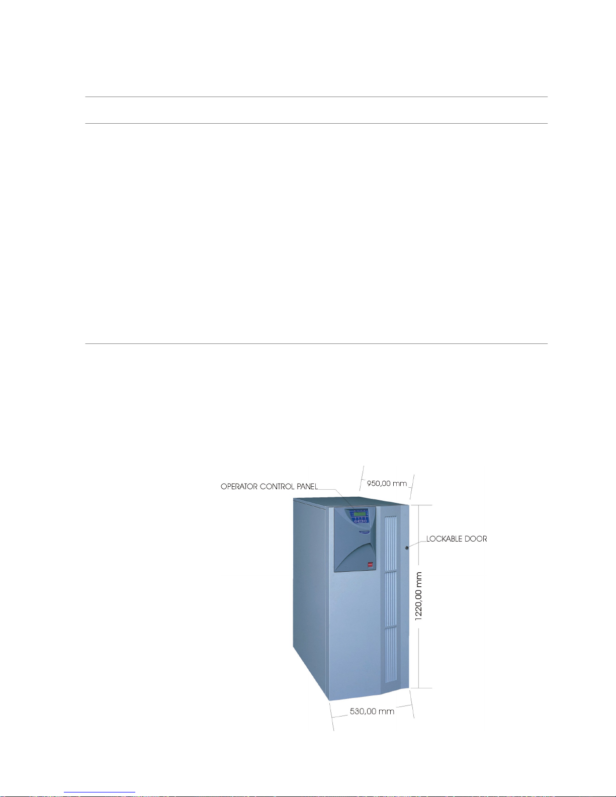
1.2 - Equipment Construction
The equipment is constructed around a steel frame with removable panels. The door which can be seĆ
cured with a key is opened to give easy access to the input, bypass, output, reserve line circuit breakers
and battery C.B. fused switch, protecting them from accidental operation.
A string LED and control panel on the front of the cabinet permits the operator to monitor the UPS.
The cabinet houses both the power components and the batteries.
It is carried on four wheels. Jacking feet help to support the UPS, and also prevent it from moving once
it has been wheeled into its final position. These feet are also used to secure the equipment to its shipĆ
ping pallet during transit.
Cooling is by internal fan. Air is drawn in from beneath the UPS and exhausted through ventilation grills
of the front panel. These areas must be kept free of anything that may avoid the air flow into and out of
the unit.
Figure 1-1Front view of cabinet.

Service ManualChapter 1 - Overview
Equipment Construction
1 - 23x3 UPS Overview
Issue 2 - November 2001
1.2.1 - Principle of operation
Normal operation
During normal operation, i.e. when the UPS input supply is present and within specification, both the
converter and inverter sections are active and the automatic byĆpass is turned on to connect the inverter
output to the critical load terminals. The battery fuseĆholder switch is also closed and the battery is thereĆ
fore permanently float charged at the d.c. terminals voltage level.
Mains Failure
If the mains has a failure or is out of tolerance the converter will be supplied from the battery, while the
Inverter will continue to operate for a period of time which depends on the load and the capacity of the
battery. If the mains supply has not returned within this time, the Inverter will go off automatically and
an alarm condition will appear on the UPS operator control panel.
Critical load will not be interrupted in the event of a drop or return of the AC power mains.
Return of power mains
When the mains returns within the required tolerance, the converter will be automatically supplied from
mains, supplying power to the Inverter and recharging the battery at the same time. There will be no
interruption of the critical load.
UPS fault
In the event of an inverter failure, the automatic byĆpass will automatically transfer the load onto the
mains with no interruption. In such an event, request qualified technical assistance.
The load will be transferred with no interruption if the inverter is synchronised with the mains; if this is
not the case, there will be an interruption of some milliseconds.
The intervention of the automatic byĆpass line is shown on the front panel by the yellow led on.
WARNING CAUTION: When the load is being supplied from the bypass line through the automatic byĆ
pass, it is connected directly to the mains supply and is therefore no longer protected
against mains faults.
Maintenance Bypass
A second bypass circuit contained in the UPS cabinet, identified as the 'Maintenance Bypass' line is
included to enable the reserve supply to be made available to the load while facilitating a safe working
environment for carrying out scheduled UPS system maintenance or trouble shooting. The circuit is
manually selected by the Manual Bypass Switch (3) which can be padlocked in the OFF position.
WARNING CAUTION CAUTION: If an automatic circuit breaker device is not present in the input disĆ
tribution panel, there remains a dangerous voltage at the output terminals and also on the
input terminals of the UPS module that is switched off.
Note: The load is not protected from mains aberrations when operating on the
maintenance bypass mode.

Service Manual Chapter 1 - Overview
Equipment Construction
1 - 33x3 UPS Overview
Issue 2 - November 2001
Figure 1-2Split Bypass" configuration
UPS
Output
UPS
Input
Battery
UPS
Split
Bypass
Link
1.2.2 - UPS Power Configuration
Common Bypass
The UPS is factory set to operate in the Common Bypass" configuration. Split Bypass links shown
in Figure 1-2 connect the Input Mains supply to the Reserve Input (Bypass) line creating a common
input. A separate Reserve Input is therefore not required.
Split Bypass
To configure the with a Split Bypass input, the Split Bypass links shown in Figure 1-2 are removed
by the commissioning engineer. In the Split Bypass" configuration the static bypass line is connected
by a separate power switch to a dedicated `bypass' power source which also feeds the maintenance
bypass line. Where a separate power source is not available the Reserve and Converter input supply
connections would be linked together.
With the exception of the maintenance bypass switch (3), all the isolators shown must be closed during
normal UPS operation.
1.2.3 - Battery fuses switch
The battery is connected to the d.c. bus through a battery fuses switch (5) fitted inside the UPS cabinet


2 - 13x3 UPS Installation
Issue 2 - November 2001
Chapter 2 - Installation
2.1 - Installation (Mechanical)
2.1.1 - Preliminary Checks
Before installing the UPS hardware the following preliminary checks must be carried out:
1. Verify that the UPS room satisfies the environmental conditions stipulated in the equipment
specification, paying particular attention to the ambient temperature and air exchange
system.
Material admittance
1. Remove any packaging debris, then visually examine the UPS and battery equipment for
transit damage, both internally and externally.
Report any such damage to the shipper immediately.
2. Ascertain that the material supplied corresponds with that on the freight bill.
Identification
The equipment supplied is provided with an adhesive identification label placed on the UPS rear panel
reporting type of UPS model and power.
The cases used to transport the equipment must be unpacked as specified by the procedure stated
below.
Packing material removal
During this operation observe the indications (FRAGILE, UP) printed on the case to avoid damaging the
UPS
To remove the packing material proceed in the following manner:
1. Place the equipment on the floor as instructed on the outer case (UP, DOWN).
2. Cut the tape and open the flaps at the top of the cardĆboard box.
3. Remove the extruded elements used as protective packing.
4. Position the forks of the lifting truck under the UPS taking care not to damage the UPS
castors and lift it a few centimetres from the floor. Back up the forklift and position the UPS.
Lower to the floor.
Hinet is provided with wheels to allow ease of movement.
5. Retain the packing material.
The original transit packing should be used if the equipment is be returned to the
maintenance centre, or moved to another position.
6. Check that the equipment has not been damaged.
Any damage should immediately be reported to the Sales Representative.
7. Locate the four battery fuses. Do not fit at this point.
8. Locate the door key and panel bolt spanner secured on the rear of the UPS. Retain for future
use.
9. The operator manual and communication cable are located behind the hinged front door.
Moving the cabinets
WARNING Ensure that any lifting equipment used for moving the UPS cabinet has sufficient lifting caĆ
pacity.
Ensure that the UPS weight is within the designated surface weight loading (Kg/cm2) of any
handling equipment. See the UPS specification for weight details.
The UPS can be lifted using a fork lift. Take care when using either method not to damage
the UPS castors located on the bottom of the unit.

Service ManualChapter 2 - Installation
Installation (Mechanical)
2 - 23x3 UPS Installation
Issue 2 - November 2001
Locating the unit in the operating position
The UPS cabinets are fitted with castors on the base to allow ease of movement and positioning. When
the equipment has been finally positioned ensure the adjustable feet are set so that the UPS will remain
stationary and stable
Ensure the following considerations are observed when locating the equipment:
a) Easy connection.
b) Enough space to ensure good access when servicing the UPS.
c) Exchange of air sufficient enough to dispel heat produced by UPS.
d) Protection against atmospheric agents.
e) Protection against excessive humidity and very high heat sources.
f) Protection against dust.
g) Compliance with the current fire prevention regulations.
h) Operating environment temperature is within +20° C and +25° C.
The batteries are at maximum efficiency in this temperature range.
Clearances
Cooling air enters the module through ventilation grills located at the bottom of the cabinet and is exĆ
hausted through the fan grills located on the front panel; you must therefore allow for a minimum gap
of 170 mm behind the unit to allow adequate air flow. Clearance around the front of the equipment
should be sufficient to enable free passage of personnel with the door fully opened.
Raised floor installation
If the equipment is to be located on a raised floor it must be mounted on a pedestal suitably designed
to accept the equipment point loading.
Refer to the base view to design this pedestal.
Cable entry
Cables enter the UPS cabinet from the rear.
UPS Mechanical Characteristics
Rated power kVA 10 15 20 30
Height mm 1220
Width mm 530
Depth mm 950
Weight:
Hinet cabinet 185
with 1 battery strings
275
with 2 battery strings
Kg
365
with 3 battery strings 455
with 4 battery strings 545
Ventilation Ć forced
Airflow full speed
Air flow half speed
m3/h
600
300
Protection grade Ć IP 20
Cable entry Ć Bottom

Service Manual Chapter 2 - Installation
Installation (Electrical)
2 - 33x3 UPS Installation
Issue 2 - November 2001
2.2 - Installation (Electrical)
The UPS requires connection of the power cables once it has been mechanically installed. All auxiliary
cables, whether screened or not, should be run separate from the power cables in metal conduits, or
metal ducts electrically bonded to the cabinet metalwork to which they are connected.
2.2.1 - Power Cabling
WARNING BEFORE CABLINGĆUP THE UPS, ENSURE THAT YOU ARE AWARE OF THE LOCATION AND
OPERATION OF THE EXTERNAL ISOLATORS THAT CONNECT THE UPS INPUT/BYPASS
SUPPLY TO THE MAINS DISTRIBUTION PANEL.
CHECK THAT THESE SUPPLIES ARE ELECTRICALLY ISOLATED, AND POST ANY NECESSĆ
ARY WARNING SIGNS TO PREVENT THEIR INADVERTENT OPERATION.
2.2.2 - Power Cable connections
The cable connection terminal block shown in Figure 2Ć1 is located at the rear of the cabinet.
1. Prepare the power cable ends and locate in the lower terminals of the terminal block.
2. Connect Input Mains to terminals 14 (U1), 15 (V1), 16 (W1) & 17 (N1).
Caution When preparing the power cables for connection, provide sufficient spare cable to allow
the UPS to be moved if necessary from it's normal operating position for servicing access.
Spare cable can be coiled beneath the unit.
3. Tighten the terminal block lower securing screws and check that each cable is secure.
4. Connected the UPS Output power cables to terminals 1 (U2), 2 (V2), 3 (W2) & 4 (N2) as
shown in Figure 2Ć1.
5. Secure the cables to the cable securing bar adjacent to the terminal block using appropriate
cable clamps.
Note: If connecting a battery to the External Battery input connections ensure
that connections are made with the correct polarity.
Split Bypass Configuration
If the UPS is to operate with a separate Reserve Input (Bypass) supply.
1. Connect the power connections for the Bypass to terminals 10 (U3), 11 (V3), 12 (W3) & 13
(N3)
2. Connect the Input Mains to terminals to 14 (U1), 15 (V1), 16 (W1) & 17 (N1) as shown in
Figure 2Ć1.
Caution When the UPS is to be operated in the Split Bypass" configuration, the Split Bypass shortĆ
ing links must first be removed by the Commissioning Engineer before Power is applied
to the unit.
Note: The maximum cable size that can be connected to the UPS power
terminal block is 25mm
2

Service ManualChapter 2 - Installation
Installation (Electrical)
2 - 43x3 UPS Installation
Issue 2 - November 2001
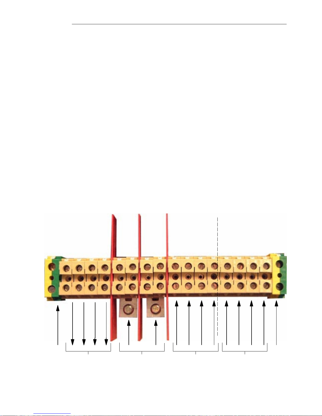
Figure 2-1Connections to distribution Terminal Block.
PE1U22V23W24N25+6+7ć8ć9U310V311W312N313U114V115W116N117PE
18
Ground
Ground
UPS Output Ext. Battery Input Reserve Input (Bypass) Input Mains
1.. Ground (ground lead for load connection) 2.. Input reserve (Bypass) phase U3
3.. Output phase U2 4.. Input reserve (Bypass) phase V3
5.. Output phase V2 6.. Input reserve (Bypass) phase W3
7.. Output phase W2 8.. Input Reserve (Bypass) Neutral N3
9.. Output Neutral N2 10.. Input Mains phase U1
11.. Battery Positive (ext. Battery input) 12.. Input Mains phase V1
13.. Battery Positive (ext. Battery input) 14.. Input Mains phase W1
15.. Battery Negative (ext. Battery input) 16.. Input Mains Neutral N1
17.. Battery Negative (ext. Battery input) 18.. Ground (Incoming ground wire from UPS
input mains connected to this terminal)
Figure 2-2 Cable Securing Bar
Cable Securing Bar

Service Manual Chapter 2 - Installation
Installation (Electrical)
2 - 53x3 UPS Installation
Issue 2 - November 2001
2.2.3 - Safety Earth
The safety earth busĆbar is located near the UPS output terminals. The safety earth cable must be conĆ
nected to the earth terminal and bonded to each cabinet in the system.
All cabinets and cable trunking must be earthed in accordance with local regulations.
WARNING FAILURE TO FOLLOW ADEQUATE EARTHING PROCEDURES CAN RESULT IN ELECTRIC
SHOCK HAZARD TO PERSONNEL, OR THE RISK OF FIRE, SHOULD AN EARTH FAULT
OCCUR.
BEFORE ANY OTHER CABLE CONNECTION THE PE SAFETY CONDUCTOR SHALL BE
CONNECTED
2.2.4 - Protective devices
Protection against earth faults (RCD devices):
In the event of a differential (RCD) device being installed upstream of the input supply, the transient and
steady state earth leakage currents that are produced during startĆup of the UPS must be taken into acĆ
count.
The presence of an RFI suppression filter inside the UPS, determines a residual earth current no greater
than 500 mA.
Residual current circuit breakers (RCCB) must be sensitive to d.c. unidirectional pulse (class A) in the
mains and insensitive to transient current pulses.

Service ManualChapter 2 - Installation
Battery Installation
2 - 63x3 UPS Installation
Issue 2 - November 2001
2.3 - Battery Installation
All UPS models are normally shipped with an internal battery fitted, therefore a thorough check
of the battery installation is required before applying power to the unit. The battery capacity, number of
cells and installation is dependent on the unit power rating and autonomy option ordered. A full break
down of the different battery configurations can be found in the Specification on preliminary page Ćxiii.
In addition to the standard battery fitted to the UPS extra strings may be added (to a maximum of 4) to
upgrade the battery autonomy. Full fitting instructions for the battery upgrade are included with each
kit, however this information has been also included in this section of the manual for continuity.
The UPS may also have an extended battery option to be fitted either in a separate or atĆ
tached cabinet, therefore the same basic checks apply.
Before
2.3.1 - Battery Safety
WARNING THE BATTERY CHAIN IS A HIGH VOLTAGE ENERGY SOURCE. WHICH CAN BE VERY DANĆ
GEROUS GIVING A POTENTIAL RISK OF SHOCK OR BURNS.
GREAT CARE SHOULD BE EXERCISED AT ALL TIMES WHEN WORKING WITH BATTERIES.
S Special care should be taken when working with the batteries associated with this
equipment.
S When connected together, the battery terminal voltage will exceed 380Vdc and is
potentially lethal.
S Eye protection should be worn to prevent injury from accidental electrical arcs.
S If a battery leaks electrolyte, or is otherwise physically damaged, it should be
placed in a container resistant to sulphuric acid and disposed of in accordance with
local regulations.
S If electrolyte comes into contact with the skin the affected area should be washed
immediately.
2.3.2 - Battery Installation Check
1. Gain access to the battery safety cover by first opening the front hinged door.
a) Disconnect the Earth bonding cable from the safety cover.
b) Remove the two top M6 retaining bolts.
c) Release the two bottom retaining bolts and lift the cover from the UPS.
2. Remove the Main Switch Cover held by four M6 retaining bolts.
3. Carefully ease the cover away from the control switches.
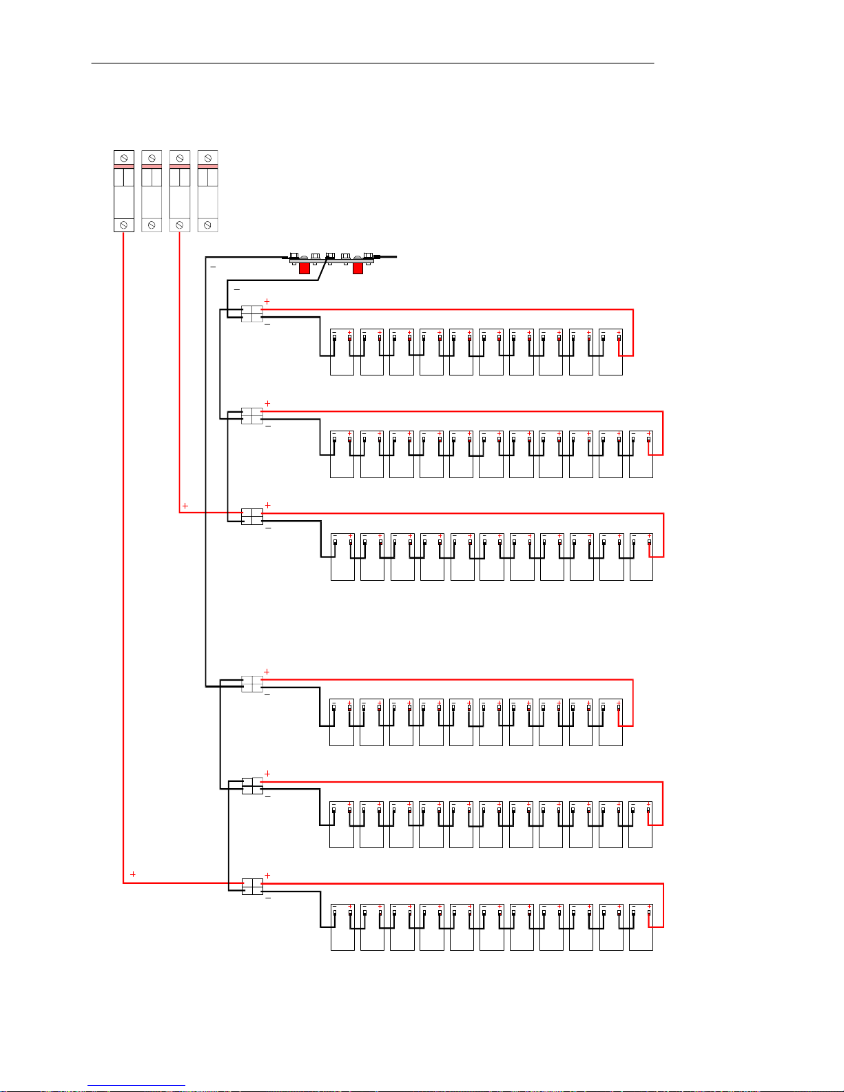
Note:Each battery string are held in 3 trays positioned as
shown in Figure 2Ć3, up to four strings can be fitted dependent on model.
4. Check the battery security in each tray.
5. Check that the FastĆon connecters to each battery are secure and that each connector is
correctly positioned on the battery terminals.
6. Check that the battery linking connectors are correct for each tray.
7. Check that the +ve cable from lower battery tray connector is connected to the correct
battery fuse, as shown in Figure 2Ć4
8. Check that the ćve battery from the top battery tray connector is secured to the common
battery ćve connection bar.
Service Manual Chapter 2 - Installation
Battery Installation
2 - 73x3 UPS Installation
Issue 2 - November 2001
Figure 2-3 Battery Tray Installation for one battery string
Battery Fuses (shown removed)
Battery Earth Bar
Battery String Voltage Check
Note: Battery fuses are removed for transit and should only be fitted by the
commissioning engineer. The fuses can be found with the User manual, in
the document pocket on the battery safety cover.
Battery String Voltage check
1. Ensure the battery fuses are removed from the switched fuse holders.
Warning Do not fit the battery fuses into the fuse holders or close the fuse holders.
2. With a DVM set to a DC range of above 450V, check for each individual battery string
voltage. This voltage for a serviceable battery should be between +385V and +416V DC.
3. Measure the battery string voltage from the lower connecting screw of the appropriate fuse
holder and the battery ćve connection bar. As shown in Figure 2-3
4. If a voltage of less than +385V is recorded reĆcheck the battery connections and reĆtest the
string voltage.
Note: A measured voltage substantially less then +385V DC may point to a
defective battery block this can be further isolated by disconnecting each
individual tray and carry out a further check of each tray voltage. This
should be grater than 132V for trays of 11 battery blocks and 120V for 10
blocks.
F1 F2 F3 F4
Battery Fuses
Battery ćve Connection Bar
Battery String 3 Top Battery Tray (10)
Battery String 3 Middle Battery Tray (11)
Battery String 3 Bottom Battery Tray (11)
CN1
CN2
CN3
Note: Battery strings 1 & 3 shown connected
Battery String 1 Top Battery Tray (10)
Battery String 1 Middle Battery Tray (11)
Battery String 1 Bottom Battery Tray (11)
CN1
CN2
CN3
Service ManualChapter 2 - Installation
Battery Installation
2 - 83x3 UPS Installation
Issue 2 - November 2001
Figure 2-4 Battery Cable Connections for one string
Service Manual Chapter 2 - Installation
Battery Installation
2 - 93x3 UPS Installation
Issue 2 - November 2001
2.3.3 -Installing the Battery Upgrade Kit
Note: Installation of a battery upgrade kit must only be carried out by a suitably
qualified, manufacturer approved engineer.
Kit Contents
Prior to installing the battery upgrade kit thoroughly check the items for damage and ensure that they
are in a serviceable condition.
Check that the battery kit contains the following items:
Item Description Part Nº Quantity
Mylar insulating sheet CM 0319 3
Battery tray CM 0470 3
Battery retaining bracket CM 0743 3
Lexan protection CM 0101 3
Battery cable harness OS 001 1
Adhesive foam strip ? ć
Cable holder self adhesive ? 9
Label `High Voltage' ? 3
Note: The 32 battery blocks are not included in the upgrade kit Part Nº
BATTCABLE, but are supplied separately as Battery Kit Part Nº
INTBATT.
Figure 2-5 Battery Tray Assembly
Mylar Insulating Sheet
Battery Blocks
(links fitted)
Lexan protection strip
Cable Holder
Battery Tray
Battery Cable
Retaining
Bracket
Foam Strip
Battery Tray
Mylar Insulating Sheet
(fold to fit batteries)
Battery Cable Connector
(Secure to retaining
bracket with cable tie)
Retaining Bracket
Cable Holder
Lexan protection strip

Service ManualChapter 2 - Installation
Battery Installation
2 - 103x3 UPS Installation
Issue 2 - November 2001
Battery Tray Assembly
1. Place the Mylar insulation strip on to the battery tray.
2. With a DVM check each individual battery block terminal voltage is within 12.5V to 13.0V.
Voltages measured below this may indicate a defective battery block. Refer to `Battery
Maintenance' on Page 6Ć5 Chapter 6 `Maintenance' for information on battery testing.
3. Fold the mylar insulation to fit the batteries and place the 11 battery blocks on to the battery
tray, as shown in Figure 2-5
(Note 10 battery blocks are fitted to the top battery tray.
4. Stick the adhesive foam strip to the battery fixing bracket.
5. Screw the battery retaining bracket to the battery tray.
Connect the batteries using the short battery interconnecting links.
6. Fit the lexan protection to the battery fixing bracket.
7. Place the three adhesive cable retaining clips to the lexan insulating strip, one in the middle
and one at each end.
8. Identify the cable Anderson type connecter supplied with a red and black interconnecting
cable and connect the red cable to the remaining +ve battery connection and the black
cable to the ćve battery connection.
9. Secure the cables in the cable retaining clips.
10. Secure the red cable to the battery retaining bracket at the rear of the assembled battery tray
using a cable tie supplied.
11. Stick the `High Voltage' label to the lexan insulating strip.
Repeat the above procedure for the remaining two battery trays.
Note: The upper battery tray is fitted with 10 batteries.
Battery String Connection
1. Ensure that the UPS has been powered down.
Note: When positioning the battery trays in the UPS, slight downward pressure
may be required on the front of the tray to clear the chassis metalwork at
the rear.
2. Fit the lower battery tray of 11 batteries to the lower position and secure using the battery
tray retaining bolt.
3. Fit the second battery tray of 11 batteries to the middle position and secure using the battery
tray retaining bolt.
4. Fit the upper battery tray of 10 batteries to the top position and secure using the battery tray
retaining bolt.
5. Refer to the schematic diagram (Figure ) locate the battery string interconnecting links from
the battery cable set.
6. Thread the Red +ve wire of the lower Anderson type cable connector through the
appropriate access hole and connect it to the battery fuse lower cable terminal.
Note: Fuse F1 is used for the first battery string, F2 for the second etc.
7. Thread the Black ćve wire of the top Anderson type cable connector through the appropriate
access hole and connect it to the ćve battery connection bar cable stud.
8. Connect the wiring harness connectors to the battery tray Anderson connectors.
a) CN1 to the top battery tray.
b) CN2 to the middle battery tray.
c) CN3 to the lower battery tray.
9. Secure the Anderson type battery connectors to the battery retaining bracket using the cable
ties supplied with the kit.

Service Manual Chapter 2 - Installation
Battery Installation
2 - 113x3 UPS Installation
Issue 2 - November 2001
Battery String Voltage Check
1. Ensure the battery fuses are removed from the switched fuse holders.
Warning Do not fit the battery fuses into the fuse holders or close the fuse holders.
2. With a DVM set to a DC range of above 450V, check for each individual battery string
voltage. This voltage for a serviceable battery should be between +385V and +416V DC.
3. Measure the battery string voltage from the lower connecting screw of the appropriate fuse
holder and the battery ćve connection bar. As shown in Figure 2-3
4. If a voltage of less than +385V is recorded reĆcheck the battery connections and reĆtest the
string voltage.
Note: A measured voltage substantially less then +385V DC may point to a
defective battery block this can be further isolated by disconnecting each
individual tray and carry out a further check of each tray voltage. This
should be greater than 132V for trays of 11 battery blocks and 120V for 10
blocks.

Service ManualChapter 2 - Installation
Setting Standard Relay Interface PCB
2 - 123x3 UPS Installation
Issue 2 - November 2001
2.4 - Setting Standard Relay Interface PCB
The preĆsettings required are only those which concern the interfaces wiring to any external devices,
i.e., personal computer, safety switch, remote panel.
2.4.1 - Setting Options on the standard Relay Interface
A standard Relay Card is situated on the left side of the rear panel. This card is typically supĆ
plied and is factory preĆset to operate with the PC.
When the operation is through the remote indication panel, the factory will deliver the card already preset
to operate with the remote panel.
Figure 2-6 Setting options on the standard Relay Board
FUNCTION JUMPER CLOSED JUMPER OPEN
Use With PC JP4 JP5
Use With Remote Panel JP5 JP4
EPO Enabled ć JP6
EPO Disabled JP6 ć
Note: If an optional second relay interface PCB is to be fitted Refer to the `Relay
Interface PCB CS0082' on Page 5Ć7 Chapter 5 `Functional Description'
for further information on Link settings.

Service Manual Chapter 2 - Installation
Setting Standard Relay Interface PCB
2 - 133x3 UPS Installation
Issue 2 - November 2001
2.4.2 - Relay Interface Connections
The relay interface PCB provides two sets of volt free contacts rated at 50V 1A the PCB receives the UPS
status signals from the Display Control Logic PCB Part Nº CS0073 and is connected to CN1.
Output signals from the relay interface are made to the terminal block M1 shown in Figure 2Ć7, or from
the RS232 DB9 connector P1 (fitted to later equipment only).
Figure 2-7 Relay Interface Outputs

Service ManualChapter 2 - Installation
Setting Standard Relay Interface PCB
2 - 143x3 UPS Installation
Issue 2 - November 2001
2.4.3 - Remote EPO (Emergency Power Off)
A connection is provided for a switch, which can be located remotely from the UPS, and which has the
same function as the internal EPO switch. When it is operated it shuts down the inverter, and inhibits the
static switch so that power is removed from the load.
WARNING Pressing the Remote EPO push button will turn the inverter off and remove power from the
load.
The mains input, bypass input and battery terminals still carry lethal voltages after pressing
the EPO switch. Do not remove cover from these parts.
Only competent personnel must remove protection panel held in place with screws.
2.4.4 - Emergency Power Off (E.P.O.) pushĆbutton connection
Refer to Figure 2-6 and Figure Figure 2-7 to make a pushĆbutton connection to the standard Relay
Card.
1. Obtain a suitable length (not more than 100 m.) twoĆwire cable (0.6 sq. mm cross section)
2. Connect one end of the cable to the N.C. pins of a fire preventing button.
3. Connect the other end to the standard Relay Card connector M2.
2.4.5 - Connection to Personal Computer
The UPS contains a standard DB9 Female connector located on the rear of the UPS.
Several signals are provided on this port and assigned as follow:
PIN Description
1 Low Battery (N.O.)
2 T.B.D.
3 T.B.D.
4 N.C.
5 Common
6 N.C.
7 Low Battery (N.O.)
8 Mains Fail (N.O.)
9 Mains Fail (N.O.)
Service Manual Chapter 2 - Installation
Setting Standard Relay Interface PCB
2 - 153x3 UPS Installation
Issue 2 - November 2001
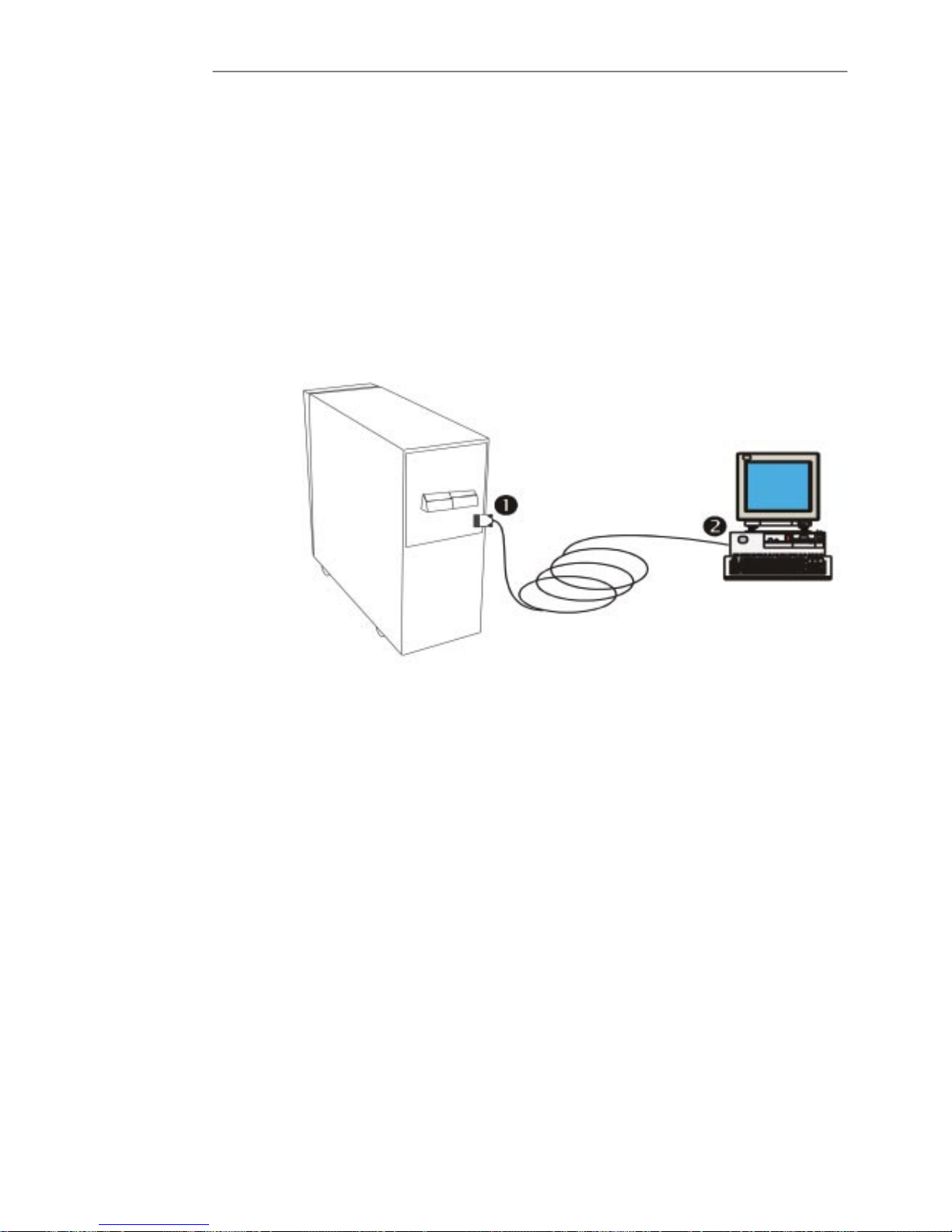
2.4.6 - UPS Monitoring
The UPS has the capability of being monitored with stand alone computers, network workstations,
network servers, or UNIx hosts via the DBĆ9 female connector (1) located on the rear of the UPS.
The capability is used in applications requiring the UPS to provide status and power monitoring informaĆ
tion to the computer system. For example, during a mains power failure, the information can be used
by the computer's operating system or application program to automatically save information in buffers,
to close files, and shutdown operations prior to battery capacity depletion.
Monitoring of the UPS via a computer system is easily made with a Liebert Multilink Software and a
special cable (2) shipped with the Unit.
Figure 2-8 UPS Monitoring cable connection


3 - 13x3 UPS Commissioning
Issue 2 - November 2001
Chapter 3 - Commissioning
3.1 - PreĆpower Checks
WARNING The UPS must be commissioned by a suitably qualified, and manufacturer approved enĆ
gineer.
Failure to ensure proper commissioning may invalidate any implied warranty.
WARNING During the commissioning procedure the UPS output terminals will become live.
If any load equipment is connected to the UPS output terminals, fully isolate it from the UPS
to ensure that no damage is caused in the extremely unlikely event of a UPS failure
WARNING During the commissioning procedure it may be necessary to power up the unit with the side
or top covers removed, in this situation exposure to potentially lethal voltages is possible
even with the input utility supply switched off.
Take great care at all times to minimise the risk of contact with live voltages, especially when
working around the battery or the dc busbar.
3.2 - Validating the Installation
Before carrying out the following checks, refer to the `Installation Manual' supplied with the equipment
or the information contained in Chapter installation in this manual.
3.2.1 - Positioning
1. Check that the UPS has been correctly positioned with at least 150mm clear space at the
rear.
2. Check that there is sufficient space at the sides of the unit to gain access.
If no access is available the UPS input and output cabling must be of sufficient length to
allow the unit to be moved forward.
3.2.2 - Preliminary checks
1. Ensure that all the UPS isolators, including he fused battery switch, are open (i.e. OFF or in
position `0').
2. Check the voltage of the input mains supply.
3. Check that the cable connections to the distribution terminal block are correct. Refer to
Figure 2Ć1 on page 2Ć4.
4. Check that the internal battery connections are secure and any external battery connected to
the Ext.Battery Input terminals are connected in the correct polarity. Refer to the `Battery
Installation' procedure on page 2Ć6.
Input mains voltage checks
1. Apply mains voltage to input terminals 14 (U1), 15 (V1), 16 (W1) & 17 (N1).
2. Measure line to line voltage of all three phases and ensure that the values are within ±10% of
nominal rating.
3. Ensure correct phase rotation clockwise R, S, T using an oscilloscope or phase rotation
meter
Note: If a split bypass is fitted, apply bypass mains voltage to the bypass
terminals 10 (U3), 11 (V3), 12 (W3) & 13 (N3) and duplicate the check for
the Input Mains.

Service ManualChapter 3 - Commissioning
Validating the Installation
3 - 2 3x3 UPS Commissioning
Issue 2 - November 2001
3.3 - Setting UPS Parameters
Check that the following factory set parameters are correct for the normal operating Conditions of the UPS.
Standard link positions are shown in bold text.
3.3.1 - Control Logic PCB CS0072.
General Operation:
LINK POSITION FUNCTION
OPEN Eco mode operation (bypass line preferred)
J1
CLOSED
Normal operation (inverter line preferred)
OPEN Bypass frequency window 4%
J
2
CLOSED Bypass frequency window 1%
OPEN Inverter output frequency 60Hz
J
3
CLOSED Inverter output frequency 50Hz
Output voltage selection:
Link 380Vac 400Vac 415Vac
J4 Open Closed Open
J5 Closed Open Open
The following link position set the UPS overload level relative to the UPS kVA rating. (As shown
on the factory rating plate)
Link 10kVA 20kVA 30kVA
J6 Open Closed Open
J7 Closed Open Closed
J8 Closed Closed Open
The following link position set the inverter and converter peak current limits which is dependent
on the UPS kVA rating. (as shown in the factory rating plate). Ensure that these links are set
according to the following table:
Link 10kVA 20kVA 30kVA
J9 Open Open Open
J10 Open Open Open
J11 Closed Closed Closed
J12 Closed Closed Closed
3.3.2 - Driver Interface PCB CS0071 Settings
Bypass value setting
Link 380Vac 400Vac 415Vac
J1A Closed Open Open
J2A Open Closed Open
J3A
Open Open Closed
Service / test mode for the secondary DC bus voltage
DC V/Link J4A J5A
375 Vdc Closed Closed
750Vdc Open Open

Service Manual Chapter 3 - Commissioning
Validating the Installation
3 - 33x3 UPS Commissioning
Issue 2 - November 2001
3.3.3 - Auxiliary DC-DC PSU Converter PCB CS0070 Settings
No link setting are required.
3.3.4 - Battery Charger PCB CS0074 Setting
Set the correct battery current limit according to the following link chart.
Link/Ampere 1Amp 3Amps 5Amps
JP1 Open Open Closed
JP2 Open Closed Open
We recommed to used the following battery current limint setting:
Battery size 7.5 Ah 2x7.5Ah 3x7.5Ah 4x7.5Ah
Battery current 1Amp 1Amp 3Amps 3Amps
Link Position Function
Open Boost recharge disable
JP3
Closed Boost recharge enable
Open Battery charger temperature compensation disable
JP4
Closed Battery charger temperature compensation enable
Battery test settings
Links JP5 to JP10 set the capacity of the standard battery, check the battery Ah to set the corĆ
rect value as shown in the table below
Link JP10 JP9 JP8 JP7 JP6 JP5
Ah 7.2Ah 2x7.2Ah 3x7.2Ah 4x7.2Ah 38Ah 65Ah
JP11 SHOULD BE ALWAYS CLOSED
Set the automatic battery test interval referring to the table below (it is recommanded to use
48h)
Link J4 J5 J6
Time 12Hours 24Hours 48Hours
3.3.5 - LCD Display Monitor Board CS0077 Settings
Used for PCB testing porposes only.
Link Position Funktion
JP1 1–2 close for normal operation.
JP3 2–3 close for normal operation.
Note: THE SILKSCREEN IDENT (JP1/JPS) IS NEXT TO PIN NUMBER 3.
LINK JP2 ( External EPO ):
JP2 is used to enable the operation of the optional external EPO.
Link Ext EPO fitted Ext EPO not fitted
JP2 Open Close

Service ManualChapter 3 - Commissioning
Validating the Installation
3 - 43x3 UPS Commissioning
Issue 2 - November 2001
3.4 - Initial UPS Start-up.
The following procedure describes the start-up and calibration of the UPS at the initial Start-up.
Figure 3-1 Operator Control Panel
Note: The following instructions refer to the controls on the UPS OPERATOR PANEL
(shown above). The user interface consits of 4 status indica tor LEDs (la bled 1-4),
a LCD panel and 4 control push buttons (labled a-d).
3.4.1 - Converter and Inverter Output Calibration.
The Secondary DC bus and Inverter Output settings will be automatically set by the Voltage parameters set on the
UPS Control Boards (see Setting UPS Parameter Section for more details).
The following table shows the correct levels of the Inverter AC volts and the Secondary DC Bus volts, depending
on the Voltage Parameters:
Voltage Parameter/
Inverter AC (L–L) Voltage.
Secondary DC Bus Voltage.
380Vac 715Vdc
400Vac 750Vdc
415Vac 800Vdc
Before starting the UPS connect a DVM set to DC volts to the UPS Secondary DC bus as shown below:
Figure 3-2 DC Bus Voltage check
F2
F3
Check Secondary DC bus
between Fuse F3 & F2
765V DC
Service Manual Chapter 3 - Commissioning
Validating the Installation
3 - 53x3 UPS Commissioning
Issue 2 - November 2001
1. Close the MAINS INPUT MCB (I1).
2. Close the UPS OUTPUT MCB (I4).
3. Wait approx. 20 seconds and check that the following sequence occurs:
D The Operator display Panel LCD energises (if required adjust Language settings as described in
chapter 4).
D The Red `ALARM' (2) LED illuminates.
D The Alarm Buzzer sounds.
D The Secondary DC Bus has risen to approx. 650Vdc (shown on the DVM).
4. Start the Inverter using the following procedure:
a) Press the `MENU' push button (a) on the FRONT PANEL.
b) Select the `COMMAND' screen by pressing either the `BACK' (c) or `NEXT' (b) push button.
c) Confirm the `COMMAND' menu selection by pressing the `BACK' and `NEXT' push-buttons at the same
time (i.e. ENTER).
d) Select the `INVERTER ON- OFF' screen by pressing either the `BACK' (c) or `NEXT' (b) push button.
e) To start Inverter, press `BACK' and `NEXT' at the same time.
D A *CONFIRMED* message will be displayed.
D The Inverter Section will now be started and be brought on-line.
f) Press `CLEAR' (d) twice to return to the main menu.
5. Wait 20 seconds and confirm that:
D The Green `LOAD on INV' LED has illuminated.
D Using the DVM check that the Secondary DC has risen to within 1% of the appropriate level shown in the
table above (e.g. 750Vdc for a 400Vac installation).
If required the level of the secondary DC bus can be adjusted using the Potentiometer P2 on the 3 Phase Control
Logic PCB (CS0072).
Note: Turn P2 Counter-Clock Wise (CCW) to increase the Secondary DC Bus.
6. Remove the DVM from the DC bus, set it to AC Volts and reconnect to the UPS output terminals (2 and 3) to
give a Line to Line voltage measurement. As shown below:
Figure 3-3Connections to distribution Terminal Block
PE1U22V23W24N25+6+7ć8ć9U310V311W312N313U114V115W116N117PE
18
Ground
Ground
UPS Output Ext. Battery Input Reserve Input (Bypass) Input Mains
7. Check that the Inverter Output Voltage has risen to within 1% of the appropriate level (e.g. 400Vac).
If required the level of the Inverter AC can be adjusted using the Potentiometer P1 on the 3 Phase Control Logic
PCB (CS0072).
Note: Turn P1 Counter-Clock Wise (CCW) to increase the Inverter Output Voltage.

Service ManualChapter 3 - Commissioning
Validating the Installation
3 - 63x3 UPS Commissioning
Issue 2 - November 2001
3.4.2 - Inverter to Bypass Synchronisation Check.
The following procedure describes the checking of the Inverter Phase-lock-loop circuit.
1. Using an appropriate oscilloscope connect:
Probe 1 to the Reserve Mains `U' phase voltage (termial 10).
Probe 2 to the UPS Output `U' phase voltage (terminal 2).
Note:Note: Use the Reserve Mains Neutral (termial 13) should be used a common
reference, therefore the scope channels should be set to differential mode.
2. Close the RESERVE MAINS MCB (I2).
3. Ensure that:
D The LCD shows the message:
BYPASS LINE WITHIN LIMITS
D The Zero crossings of the Inverter and Bypass sinewaves are synchronised.
3.4.3 - Battery Charger Output Calibration.
The following procedure describes the calibration of the UPS's Battery charger output.
Connect a DVM set to DC Volts to the UPS's External Battery terminals (+ve at terminals 6 or 7 and ćve at terminals
8 or 9).
Ensure that:
D The DC value at the battery terminals is at 432Vdc +/-1%.
If required the Battery Charger voltage can be adjusted using the potentiometer P1 on the Battery Charger Board
(CS0070).
Note: Turn P1 Counter-Clock Wise (CCW) to increase the Battery Charger Output Voltage.
Insert the appropriate number of fuses into the INTERNAL BATTERY Fused Switch (I5) and Close.
Ensure that:
The red `ALARM' LED extinguishes.
The green `NORMAL' LED illuminates.
The LCD shows a `- UPS in Operation ć` heading.
THE START UP AND CALIBRATION OF THE UPS IS NOW COMPLETE.

Service Manual Chapter 3 - Commissioning
Validating the Installation
3 - 73x3 UPS Commissioning
Issue 2 - November 2001
3.5 - Power Checks
Once the initial start up and commissioning have been completed the UPS should be functionally checked and
before connecting to the critical load.
The following procedure describes the recommended functional checks:
3.5.1 - Bypass failure test.
3.5.2 - Mains failure checks.
3.5.3 - Load Transfer Test
3.5.4 - Maintenance bypass check.
3.5.5 - Internal EPO check.
3.5.6 - External EPO (if required).
3.5.1 Bupass Failure Test
The purpose of this test is to ensure that the UPS correctly recognises a Bypass failure (simulated by opening the
Reserve MCB) and that the Inverter remains stable.
1. Open the `RESERVE INPUT' MCB. ( I2 ).
2. On the LCD ensure that the following alarms are displayed:
D UPS ALARM ć (heading)
D MAINS WITHIN LIMITS.
D BATTERY VOLTAGE WITHIN LIMITS.
D INVERTER OPERATING.
D LOAD ON INVERTER.
D BYPASS LINE OUT OF LIMITS.
D The green `NORMAL' LED ( 1 ) will extinguish.
D The red `ALARM' LED ( 2 ) will illuminate.
D The green `LOAD on INV' LED ( 3 ) remains illuminated.
D The alarm buzzer should sound, press `CLEAR' (d) push button to silence the alarm.
3. Using a DVM check that the output Voltage and frequency at output terminals is correct (e.g. 400Vac and
50Hz).
4. Close the `RESERVE INPUT' MCB. ( I2 )
5. The UPS should now return to normal Operation.
Ensure that:
D The `ć UPS in Operation ć` returns to the LCD.
D The green `NORMAL' LED ( 1 ) has illuminated,
D The red `ALARM' LED ( 2 ) has extinguished,
D The yellow `BYPASS ON' LED ( 4 ) has extinguished
D The green `LOAD-on-INV' LED ( 3 ) has illuminated.
3.5.2 Mains Failure Checks
The purpose of this test is to ensure that the UPS correctly recognises a Mains Failure (Simulated by opening the
MAINS INPUT MCB) and is able to operate from the internal Battery.
1. Open the `MAINS INPUT' MCB. ( I1 )
2. On the LCD ensure that the following alarm are displayed:
D UPS ALARM ć (heading)
D MAINS OUT OF LIMITS.
D BYPASS LINE WITHIN LIMITS.
D INVERTER OPERATING.
D INVERTER-BYPASS LINE SYNCHRONIZED.
D LOAD ON INVERTER.
D The green `NORMAL' LED ( 1 ) has extinguished.
D The red `ALARM' LED ( 2 ) has illuminated.
D The green `LOAD on INV' LED ( 3 ) remains illuminated.
D The Alarm buzzer should sound, press `CLEAR' (d) push button to silence the alarm.

Service ManualChapter 3 - Commissioning
Validating the Installation
3 - 83x3 UPS Commissioning
Issue 2 - November 2001
3. Using a DVM check that the output Voltage and frequency at output Terminals is correct (e.g. 400Vac and
50Hz).
Using a DVM check that the Battery Voltage at the battery Terminals is correct (405V +/- 10V).
4. Close the `MAINS INPUT' MCB (I1).
The UPS should now return to normal Operation.
Ensure that:
D The `ć UPS in Operation ć` returns to the LCD.
D The green `NORMAL' LED ( 1 ) has illuminated,
D The red `ALARM' LED ( 2 ) has extinguished,
D The yellow `BYPASS ON' LED ( 4 ) has extinguished
D The green `LOAD-on-INV' LED ( 3 ) has illuminated.
3.5.3 Test Transfer to the Reserve Line (Automatic Bypass).
Testing the transfer to the reserve bypass line, is carried out by forcing the automatic By-pass circuit to switch and
then checking that the load is still being powered.
If no other alarms occur, the UPS will automatically re-transfer back to inverter operation after 20 seconds on
completion of the test.
1. Press the `MENU' push button (a) on the FRONT PANEL.
a) Select the `COMMAND' screen by pressing either the `BACK' (c) or `NEXT' (b) push button.
b) Confirm the `COMMAND' menu selection by pressing `BACK' and `NEXT' at the same time (i.e. ENTER).
c) Select the `SWITCH LOAD' function by pressing either `BACK' or `NEXT'.
d) Confirm `SWITCH LOAD' function by pressing `BACK' and `NEXT' at the same time.
D A ***CONFIRMED*** message will be displayed
2. Press `CLEAR' (d) twice to return to the main menu.
The follow change over sequence will should occur:
D The yellow `BYPASS ON' LED ( 4 ) will be illuminated (UPS ON BYPASS)
D After 20 seconds the yellow `BYPASS ON' LED ( 4 ) will turn off and the load will be re-transferred back
to inverter.
D The green `LOAD on INV' LED ( 3 ) will illuminate (UPS ON INVERTER).

Service Manual Chapter 3 - Commissioning
Validating the Installation
3 - 93x3 UPS Commissioning
Issue 2 - November 2001
3.5.4 Manual Bypass Operation Check
The manual bypass allows the UPS to be switched OFF while the critical load is maintained.
The following procedure describe the confirmation of this function.
1. Press the `MENU' push button (a) on the FRONT PANEL.
a) Select the `COMMAND' screen by pressing either the `BACK' (c) or `NEXT' (b) push button.
b) Confirm the `COMMAND' menu selection by pressing `BACK' and `NEXT' at the same time (i.e. ENTER).
c) Select the `SWITCH LOAD' function by pressing either `BACK' or `NEXT'.
d) Confirm `SWITCH LOAD' function by pressing `BACK' and `NEXT' at the same time.
D A ***CONFIRMED*** message will be displayed
2. Press `CLEAR' (d) twice to return to the main menu.
The following change-over sequence should occur, indicating that the load has been transfer to the bypass line:
D The yellow `BYPASS ON' LED ( 4 ) is illuminated
D The green `LOAD on INV' LED is extinguished.
3. To turn off the Inverter follow the procedure below:
a) Press the `MENU' push button (a) on the FRONT PANEL.
b) Select the `COMMAND' screen by pressing either the `BACK' (c) or `NEXT' (b) push button.
c) Confirm the `COMMAND' menu selection by pressing `BACK' and `NEXT' at the same time (i.e. ENTER).
d) Select the `INVERTER ON-OFF' screen by pressing either the `BACK' (c) or `NEXT' (b) push button.
e) Confirm `INVERTER OFF' function by pressing `BACK' and `NEXT' at the same time.
D A ***CONFIRMED*** message will be displayed
f) Press `CLEAR' twice to return at the main screen.
4. The follow sequence should occur:
D The Alarm buzzer is activated.
D The Red general `ALARM' red LED ( 2 ) will illuminate.
D The Yellow `BYPASS ON' LED ( 4 ) will illuminate.
D The Green `NORMAL' LED will extinguish.
D The LCD will display the following messages:
`LOAD ON BYPASS' and
`INVERTER OFF'.
5. Remove the Mechanical Lock from the MANUAL BYPASS MCB ( I3 )
6. Close the. MANUAL BYPASS MCB ( I3 )
7. Open the `UPS OUTPUT' MCB ( I4 ).
8. Open the `MAINS INPUT' MCB ( I1 ).
9. Open the `RESERVE INPUT' MCB ( I2 ).
10. Open the `INTERNAL BATTERY' fused switch ( I5 ).
11. Check that the load continues to be powered from the Maintenance Bypass Mains supply while the UPS is
off.
RETURN FROM MANUAL BYPASS TO NORMAL OPERATION
1. Close the `RESERVE INPUT' MCB. ( I2 )
D wait until the fan is running, indicating that the output voltage is present.
2. Close the `MAINS INPUT' MCB. ( I1)
Wait until the Operator panel shows the following indications:
D LCD is energize and
D The alarm buzzer sounds.
D The red `ALARM'LED ( 2 )
D The yellow `BYPASS ON' LED will illuminate.
3. Close the `INTERNAL BATTERY' fused switch. ( I5 ).
4. Close the `UPS OUTPUT' MCB. ( I4 ).
5. Open the `MANUAL BYPASS' MCB. ( I3 ).
6. Start the inverter as follow:
a) Press the `MENU' push button (a) on the FRONT PANEL.
b) Select the `COMMAND' screen by pressing either the `BACK' (c) or `NEXT' (b) push button.
c) Confirm the `COMMAND' menu selection by pressing `BACK' and `NEXT' at the same time (i.e. ENTER).

Service ManualChapter 3 - Commissioning
Validating the Installation
3 - 103x3 UPS Commissioning
Issue 2 - November 2001
d) Select the `INVERTER ON- OFF' screen by pressing either the `BACK' (c) or `NEXT' (b) push button.
e) Confirm `INVERTER ON' function by pressing `BACK' and `NEXT' at the same time.
D A ***CONFIRMED*** message will be displayed
f) Press `CLEAR' (d) twice to return at the main screen.
7. Within approximately 20 sec. and the follow sequence should occur:
D The green `NORMAL' LED ( 1 ) has illuminated.
D The red `ALARM' LED ( 2 ) has extinguished.
D The yellow `BYPASS ON' LED ( 4 ) has extinguished.
D The green `LOAD-on-INV' LED ( 3 ) has illuminated.
Place the mechanical lock, onto the `MANUAL BYPASS' MCB.
The UPS is now in the normal operating condition with the Inverter supplying the load.
3.5.5 Local EPO
The following procedure describes the testing of the UPS's Emergency Power Off (EPO) functions.
The activation of the EPO circuit will shutdown all UPS functions, causing the disconnection of the Critical Load.
Ensure that it is safe to carry out this test before proceeding.
1. Press the front panel EPO push button and hold it for at least 3 seconds to confirm it.
2. All UPS functions will stop and UPS will disconnect the critical load.
Check that the following indications are seen:
D The Alarm buzzer sounds.
D The red `ALARM' LED has illuminated.
D The green `NORMAL' LED has extinguished
D The green `LOAD-on-INV' has extinguished.
D The LCD shows the alarm `EMERGENCY POWER OFF'.
To restart the UPS after an EPO, carry out the following procedure:
1. Open the `UPS OUTPUT' MCB. ( I4)
2. Open the `INTERNAL BATTERY' fused switch. ( I5 )
3. Open the `RESERVE INPUT' MCB. ( I2 )
4. Open the `MAINS INPUT' MCB. ( I1 )
D Wait until the display has de-energized.
5. Restart the UPS by following the start up procedure in chapter 3.4.
3.5.6 External EPO
The following procedure describes the testing of the UPS's Emergency Power Off (EPO) functions.
The activation of the EPO circuit will shutdown all UPS functions, causing the disconnection of the Critical Load.
Ensure that it is safe to carry out this test before proceeding.
1. Press the External EPO push button and hold it for at least 3 seconds to confirm it.
2. All UPS functions will stop and UPS will disconnect the critical load.
Check that the following indications are seen:
D The Alarm buzzer sounds.
D The red `ALARM' LED has illuminated.
D The green `NORMAL' LED has extinguished
D The green `LOAD-on-INV' has extinguished.
D The LCD shows the alarm `EMERGENCY POWER OFF'.
To restart the UPS after an EPO, carry out the following procedure:
3. Open the `UPS OUTPUT' MCB. ( I4)
4. Open the `INTERNAL BATTERY' fused switch. ( I5 )
5. Open the `RESERVE INPUT' MCB. ( I2 )
6. Open the `MAINS INPUT' MCB. ( I1 )
D Wait until the display has de-energized.
7. Restart the UPS by following the start up procedure in chapter 3.4.

Service Manual Chapter 3 - Commissioning
Validating the Installation
3 - 113x3 UPS Commissioning
Issue 2 - November 2001
3.6 - Normal UPS Start-Up Instructions
After calibration the following procedure can be used to activate the UPS:
Figure 3-4ups power switches
I2
RESERVE INPUT MCB
I1
MAINS INPUT MCB
I3
MANUAL BYPASS MCBI4UPS OUTPUT MCBI5INTERNAL BATTER Y
FUSED SWITCH
1. Close the RESERVE INPUT MCB (Miniature Circuit Breaker) (I2).
2. Close the UPS OUTPUT MCB (I4).
D Wait until the fan is running, indicating that the output voltage is present.
3. Close the MAINS INPUT MCB (I1).
D The display will energize, the `BYPASS ON' (4) and the `ALARM' (2) LEDs will illuminate (see figure 3-3).
D The Alarm Buzzer will sound.
4. Fit the battery fuses into the fused battery switch. (The fuses are removed for transit and can be found with
the User manual in the document pocket on the battery safety cover).
5. Close the `INTERNAL BATTERY' fused switch. (I5).
6. Check the status of the UPS Operator Panel:
D The Amber `BYPASS ON' ( 4 ) LED will be illuminated
D The red `ALARM' (2) led will be illuminated.
D The LCD will display the following messages:
MAINS WITHIN LIMITS;
BY-PASS LINE WITHIN LIMITS;
BATTERY VOLTAGE WITHIN LIMITS;
LOAD ON BY-PASS and
INVERTER OFF.
7. To Silence the buzzer press the`CLEAR' (d) push button.
8. To Start the Inverter carry out the following instructions:
a) Press the `MENU' push button (a) on the FRONT PANEL.
b) Select the `COMMAND' screen by pressing either the `BACK' (c) or `NEXT' (b) push button.
c) Confirm the `COMMAND' menu selection by pressing the `BACK' and `NEXT' push-buttons at the same
time (i.e. ENTER).
d) Select the `INVERTER ON- OFF' screen by pressing either the `BACK' (c) or `NEXT' (b) push button.
e) To start Inverter press `BACK' and `NEXT' at the same time.
D A *CONFIRMED* message will be displayed.
D The Inverter Section will now be started and be brought on-line.
f) Press `CLEAR' (d) twice to return to the main menu.
9. After 20 seconds:
D The Amber `BYPASS ON' LED ( 4 ) will extinguish.
D The Green `LOAD on INV'LED will illuminate.
D the Green `NORMAL' LED will illumunate.
THE UPS IS NOW IN THE NORMAL OPERATING CONDITION.

Service ManualChapter 3 - Commissioning
Validating the Installation
3 - 123x3 UPS Commissioning
Issue 2 - November 2001
3.6.1 - LCD Messages and LED status after starting the UPS.
During the Normal Operation of the UPS LCD panel will show the following messages:
D MAINS WITHIN LIMITS.
D BYPASS LINE WITHIN LIMITS.
D BATTERY VOLTAGE WITHIN LIMITS.
D INVERTER OPERATING.
D INVERTER-BYPASS LINE SYNCHRONIZED.
D LOAD ON INVERTER.
D The `NORMAL' green LED ( 1 )and the `LOAD on INV' green LED ( 3 ) are illuminate. The buzzer alarm is off.
Note:Note: for a full explanation of the control panel LCD and LED function refere to
chapter 4.
3.7 - Normal Shutdown to Manual Bypass
After calibration the following procedure can be used to shutdown the UPS to a Manual bypass condition, and then
to normal operation:
1. Press the `MENU' push button (a) on the FRONT PANEL.
a) Select the `COMMAND' screen by pressing either the `BACK' (c) or `NEXT' (b) push button.
b) Confirm the `COMMAND' menu selection by pressing `BACK' and `NEXT' at the same time (i.e. ENTER).
c) Select the `SWITCH LOAD'function by pressing either `BACK' or `NEXT'.
d) Confirm `SWITCH LOAD' function by pressing `BACK' and `NEXT' at the same time.
D A *CONFIRMED* message will be displayed
2. Press `CLEAR' (d) twice to return to the main menu.
The following change-over sequence should occur, indicating that the load has been transfer to the bypass line:
D The yellow `BYPASS ON' LED ( 4 ) is illuminated
D The green`LOAD on INV' LED is extinguished.
3. To turn off the Inverter follow the procedure below:
a) Press the `MENU' push button (a) on the FRONT PANEL.
b) Select the `COMMAND' screen by pressing either the `BACK' (c) or `NEXT' (b) push button.
c) Confirm the `COMMAND' menu selection by pressing `BACK' and `NEXT' at the same time (i.e. ENTER).
d) Select the `INVERTER ON-OFF' screen by pressing either the `BACK' (c) or `NEXT' (b) push button.
e) Confirm `INVERTER OFF' function by pressing `BACK' and `NEXT' at the same time.
D A **CONFIRMED** message will be displayed
f) Press `CLEAR' twice to return at the main screen.
4. The follow sequence should occur:
a) The Alarm buzzeris activated.
b) the Red general `ALARM' red LED ( 2 ) will illuminate.
c) the Yellow `BYPASS ON' LED ( 4 ) will illuminate.
d) the Green `NORMAL' LED will extingaquish.
e) The LCD will display the following messages:
`LOAD ON BYPASS' and `INVERTER OFF'.
5. Remove the Mechanical Lock from the MANUAL BYPASS MCB ( I3 )
6. Close the. MANUAL BYPASS MCB ( I3 )
7. Open the `UPS OUTPUT' MCB ( I4 ).
8. Open the `MAINS INPUT' MCB ( I1 ).
9. Open the `RESERVE INPUT' MCB ( I2 ).
10. Open the `INTERNAL BATTERY' fused switch ( I5 ).
11. Check that the load continues to be powered from the Maintenance Bypass Mains supply while the UPS is
off.

Service Manual Chapter 3 - Commissioning
Validating the Installation
3 - 133x3 UPS Commissioning
Issue 2 - November 2001
RETURN FROM MANUAL BYPASS TO NORMAL OPERATION
1. Close the `RESERVE INPUT' MCB. ( I2 )
D wait until the fan is running, indicating that the output voltage is present.
2. Close the `MAINS INPUT' MCB. ( I1)
Wait until the Operator panel shows the following indications:
D LCD is energize and
D The alarm buzzer sounds.
D The red `ALARM'LED ( 2 )
D The yellow `BYPASS ON' LED will illuminate.
3. Close the `INTERNAL BATTERY' fused switch. ( I5 ).
4. Close the `UPS OUTPUT' MCB. ( I4 ).
5. Open the `MANUAL BYPASS' MCB. ( I3 ).
6. Start the inverter as follow:
a) Press the `MENU' push button (a) on the FRONT PANEL.
b) Select the `COMMAND' screen by pressing either the `BACK' (c) or `NEXT' (b) push button.
c) Confirm the `COMMAND' menu selection by pressing `BACK' and `NEXT' at the same time (i.e. ENTER).
d) Select the `INVERTER ON- OFF' screen by pressing either the `BACK' (c) or `NEXT' (b) push button.
e) Confirm `INVERTER ON' function by pressing `BACK' and `NEXT' at the same time.
D A **CONFIRMED** message will be displayed
f) Press `CLEAR' (d) twice to return at the main screen.
7. Within approximately 20 sec. and the follow sequence should occour:
D The green `NORMAL' LED ( 1 ) has illuminated.
D the red `ALARM' LED ( 2 ) has extinguished.
D the yellow `BYPASS ON' LED ( 4 ) has extinguished.
D the green `LOAD-on-INV' LED ( 3 ) has illuminated.
8. Place the mechanical lock, onto the `MANUAL BYPASS' MCB, or secure with a Pad-lock.
The UPS is now in the normal operating condition with the Inverter supplying the load.

Service ManualChapter 3 - Commissioning
Setting Options
3 - 143x3 UPS Commissioning
Issue 2 - November 2001
3.8 - Setting Options
The preĆsetting checks required are to the relay interfaces PCB links and wiring, to any fitted external
devices, i.e. personal computer, EPO switch, remote panel.
3.8.1 - Setting options on the Relay card
The relay card is supplied as an option at the customers request. If supplied the card shall have to be
preset according to specific Customer requirements.
The link configuration required for the application with a PC or with the remote indication panel is deĆ
scribed in the following table. Output signals from the relay interface are used for the control of customer
peripheral computer equipment and connections are made to the terminal block M1 shown in Figure
3Ć6, or from the RS232 DB9 connector P1 (fitted to later equipment only).
Figure 3-5 Setting options on the Relay card
Table 3-1 Relay Interface PCB Output
Link
Relay UPS Function Signal Function
JP4 JP5
Mains NOT OK Closed Open
RL1 MAINS STATUS
Mains OK Open Closed
RL2 BYĆPASS ON
RL3 UPS Ć RUN
No associated link
RL4
PREĆALARM
No associated link
Links fitted to the PCB allow the input mains status to be set and the serial port P1 to be enabled as shown
in Table 3-2. These signals are generated on the display control logic PCB and connected to the relay
PCB at connector CN4.

Service Manual Chapter 3 - Commissioning
Setting Options
3 - 153x3 UPS Commissioning
Issue 2 - November 2001
Table 3-2 Serial Port P1 DB9 Connector Connections
Link
Pin
Nº
Function Relay
JP1 JP2 JP3 JP4 JP5
5 COMMON N/A Closed ć ć
3 UPS RX N/A ć Closed ć
ć
2 UPS TX N/A ć ć Closed
89MAINS
STATUS
RL1 ć
MainsĆ
NOK
MainsĆOK
1
7
PRE ALARM RL4 ć
Figure 3-6 Relay Interface Outputs


4 - 13x3 UPS Operation and control
Issue 2 - November 2001
Chapter 4 - Operation and control
4.1 - Operator Control Panel
Introduction
On the front of the UPS there is a control panel, from which it is possible to easily verify the status of the UPS, battery
and alarms. The operator control panel consists in a LCD display that indicates the operational and alarm status of
the UPS and the EPO push-button that is located at the left side.
The LCD Display Panel displays textual messages and operating parameters on a LCD screen capable of showing
4 rows of 20 characters.
The displayed screen is organized in a multi-level menu system and selected by using push button located to the
right of the screen
Figure 4-1 UPS Operator control panel
LCD control panel
Figure 4-2 LCD Display make-up

Service ManualChapter 4 - Operation and control
Operator Control Panel
4 - 23x3 UPS Operation and control
Issue 2 - November 2001
Control panel indicator LEDs
The Table 4-1 shows that the menu contains three levels. The main level is the State and Alarm Menu.
In this menu it is possible to see the state and operative condition of the UPS, the CLEAR Button is used to scroll
through the different windows of this menu.
From the main menu the User may have access to different menu pressing the MENU Button (second level).
Once in this level the first row will show < menu choice > and the NEXT and BACK push Button enable the User
to move from one menu level to another.
Pressing both NEXT and BACK push button at the same time the ENTER command is selected and the next lower
level will be reached, while CLEAR take you back to the previous level. To verify the acquisition of ENTER a Beep
will be heard and CONFIRMED will appeared on the Display.
The NEXT/BACK selector keys are used to scroll through different windows in the same menu.
Table 4-1 LCD Display Main Menu Path
STATUS ALARM MENU
MENU
CLEAR
ENTER
NEXT
BACK
COMMAND MODE
NEXT
BACK
EVENT HISTORY
NEXT
BACK
OPERATING LANGUAGE
NEXT
BACK
CLOCK
NEXT
UPS CONFIGURATION
NEXT
BACK
BATTERY TEST
NEXT
BACK
SWITCH LOAD
NEXT
INVERTER ON–OFF
NEXT
BACK
DISPLAY EVENTS
NEXT
DELETE EVENTS
ENTER
NEXT BACK
ITALIAN
NEXT
BACK
ENGLISH
NEXT
FRENCH
NEXT
BACK
GERMAN
NEXT
SPANISH
ENTER
BACK
NEXT
BACK
SERIAL NUMBER
NEXT
BACK
PHONE NUMBER
NEXT
BATTERY CAPACITY
ENTER
BACK
CALIBRATION
NEXT
NEXT
BACK
DATE
NEXT
HOUR
ENTER
CLEAR
CLEAR
CLEAR
CLEAR
CLEAR
BATTERY VOLTAGE
WITHIN LIMITS
BYPASS LINE
WITHIN LIMITS
MAIN WITHIN
LIMTTS
INVERTER – BYPASS
SYNCRONISED
LOAD ON INVERTER
LOAD ON BYPASS
INVERTER OPERATING
CLEAR
CLEAR
CLEAR
CLEAR
CLEAR
CLEAR
CLEAR
CLEAR
CLEAR
CLEAR
CLEAR
CLEAR
CLEAR
CLEAR
CLEAR
CLEAR
CLEAR
CLEAR
CLEAR
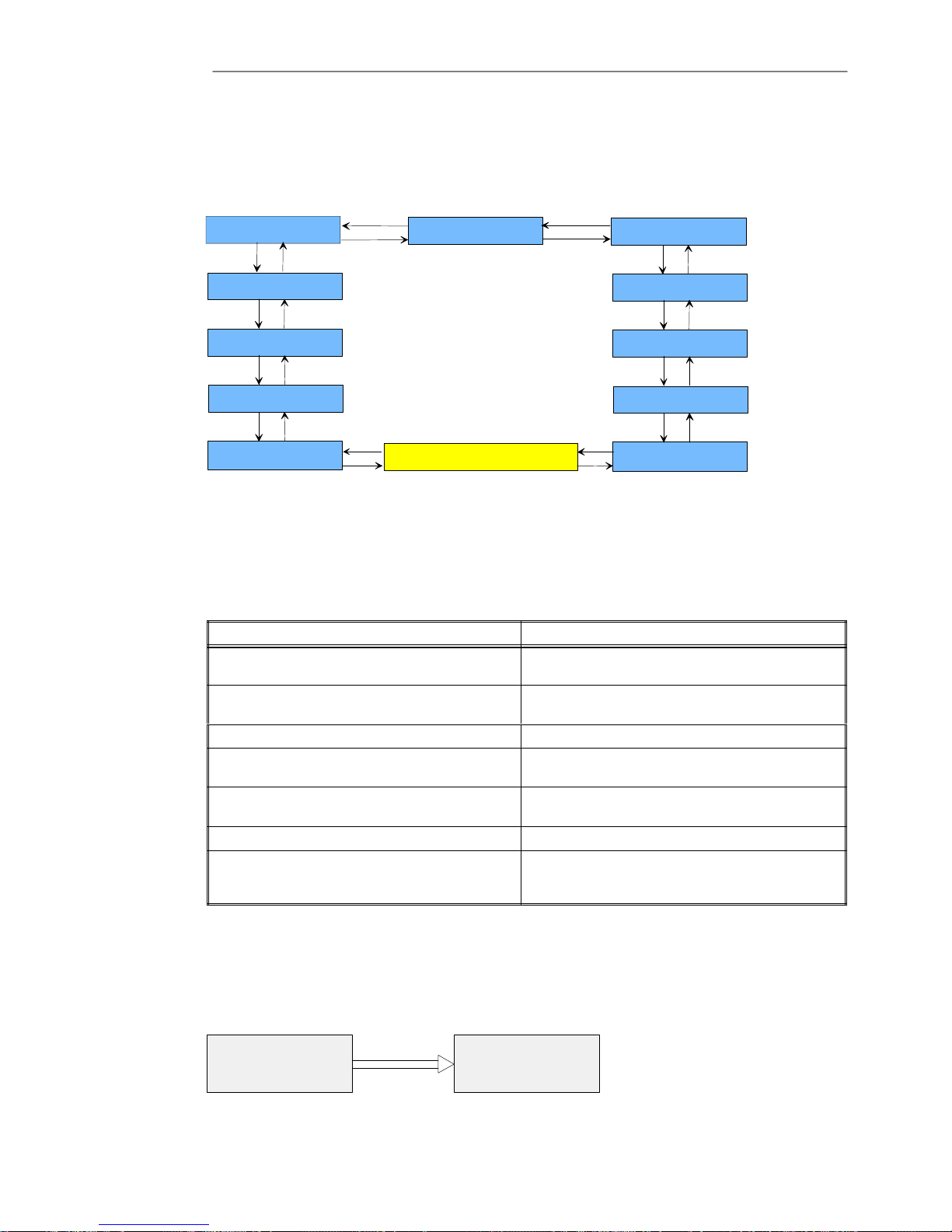
Service Manual Chapter 4 - Operation and control
Operator Control Panel
4 - 33x3 UPS Operation and control
Issue 2 - November 2001
From the main menu (STATUS ALARMS MENU) the User may have also access to the Input/Output measured paraĆ
meters and the internal parameters as well as the UPS temperature and the battery back-up time.
To scroll through these parameters use Next and Back Push Buttons. (see Table 4-2)
Table 4-2 Input/Output Parameters Menu
STATUS ALARM MENU
INPUT VOLTAGE
Phase/Neutral Vrn,Vsn,Vtn
NEXT
BACK
NEXTBACK
INPUT VOLTAGE
Phase/Phase Vrs,Vst,Vtr
NEXTBACK
OUTPUT VOLTAGE
Phase/Neutral Vrn,Vsn,Vtn
NEXTBACK
OUTPUT VOLTAGE
Phase/Phase Vrs,Vst,Vtr
NEXT
BACK
NEXT
BACK
NEXT
BACK
NEXT
BACK
NEXT
BACK
NEXT
BACK
OUTPUT CURRENT
Ir , Is , It
NEXTBACK
NEXTBACK
INPUT CURRENT
Ir , Is , It
BATTERY
V, I , Autonomy: %
FREQUENCY
fin, fout
UPS TEMPERATURE
t emp.
OUTPUT POWER
kW , kVA, cos
UPS SETTING
fout, Vout
STATUS ALARM MENU
This menu is characterized by the first raw of the message that can be UPS IN OPERATION or UPS ALARM, depenĆ
ding whether the status of the UPS is in normal operation or an alarm condition has been detected. The meaning
of the message given are the following.
UPS in Operation
MESSAGE INTERPRETATION
MAIN WITHIN LIMITS
The Main Input Line is present and the voltage is in
the specified range
BYPASS LINE WITHIN LIMITS
The Input Bypass Supply Line is present and the volĆ
tage is within the specified tolerance
BATTERY VOLTAGE WITHIN LIMITS The Battery voltage is within specifications limits
INVERTER OPERATING
The inverter is turned-on and behave with regularity
operation
INVERTER ć BYPASS SYNCRONISED
Indication of regular synchronism state between inverĆ
ter and bypass line
LOAD ON INVERTER The load is supplied from the inverter
LOAD ON BYPASS
The load is supplied from the bypass line. This can be a
temporary condition lasting for 20 sec when a fast overĆ
load occurs.
UPS in Alarm
In case of a failure in the UPS, the default screen will be replaced by the Alarm Screen. In this display the User will
have an overview on the type of malfunction occurred .A buzzer will be activated and can be cleared by pressing
CLEAR button. In this screen by pressing ENTER it will be shown a list of instruction to guide the Operator to underĆ
stand the meaning of the Alarm. The CLEAR push button allow to scroll through different messages As the alarm
condition is removed the current default screen will be displayed.
UPS ALARM
TYPE OF ALARM
ENTER
CAUSE OF THE ALARM
ACTIONS
ENTER

Service ManualChapter 4 - Operation and control
Operator Control Panel
4 - 43x3 UPS Operation and control
Issue 2 - November 2001
The List of possible Alarm and the associate help messages is displayed below.
ALARM MESSAGE
CAUSE ACTION
INVERTER OFF
Initial Start Up
Permanent Overload has been deĆ
tected
Start the Inverter
Check Output
INVERTER OVERLOAD
Continuos Overload on UPS OutĆ
put
Check Output Load and Restart
Inverter
Check for Output Short-Circuit
BYPASS SWITCH LOCKED
High Transient Loads on UPS OutĆ
put. Inrush Load Current
After 3 times
Check Output Load and Restart
Inverter
BATTERY FAILURE Battery Test not OK
Check Battery
Check Battery fuses
INVERTER SHUT-DOWN
IMMINENT
Battery almost flat, next to
Shut-Down of inverter
Make shut-down to the connecĆ
ted Loads
BYPASS SWITCH FAILURE
One or more Phases in the Output
are missing
Check SCR of Bypass
Check Bypass external connecĆ
tions
MANUAL BYPASS ON UPS on Maintenance
MAIN OUT OF LIMITS
Breaker is Open
Main Input is missing
Check Main line Voltage and
Breaker position
BYPASS LINE OUT OF
LIMITS
The input phase rotation is not corĆ
rect
Input Voltage Missing
Check Bypass line Voltage
Check Phase Rotation
EMERGENCY POWER OFF
The Command EPO has been seĆ
lected
Restart the UPS
Fully switch-off the Breakers and
the Battery Fuse, wait till the LCD
is complete switch-off then restart
the UPS
BATTERY NOT CONNECTED
Battery Switch Open
Battery Test Failed
BATTERY CHARGER FAULT
Call Service Office, to replace the
Battery Charger
HIGH BATTERY VOLTAGE LEVEL Battery Charger in Fault
Call Service Office, to replace the
Battery Charger
END OF BATTERY DISCHARGE Main is missing for long time
COMMAND MODE MENU
In this menu is possible to give some operative command to the UPS.
MESSAGE INTERPRETATION
BATTERY TEST
With this message displayed by pressing ENTER an automatic test on the
Battery will be performed instantaneously
SWITCH LOAD
With this message displayed by pressing ENTER the load is switched from
inverter to the Bypass Line. This command is also used for reset the alarm
conditions on the bypass line. For instance when the Alarm Bypass Switch
Locked is present because for three consecutive times the load has been
connected to Bypass for transient overload. To reconnect the load on inverter
is necessary to activate this command by ENTER
INVERTER ON/OFF
With this message displayed by pressing ENTER the User can Turn-on or
Turn-off the Inverter in a permanent way and connect it to the Load.
It is necessary Turn-on the Inverter at the start-up and after a permanent
overload.

Service Manual Chapter 4 - Operation and control
Operator Control Panel
4 - 53x3 UPS Operation and control
Issue 2 - November 2001
EVENT HISTORY MENU
In this menu the user may scroll through the past n°512 Alarm occurrences in chronological order.
The Event Log display can be opened from the menu EVENT HISTORY by pressing ENTER twice. The Log screen
will display Date and Time of the last EVENT occurred. The Back push button will be used to scroll Date and Time
of the previous EVENTS and the Next push button will be used to scroll other statements and Alarm Messages conĆ
nected to the same EVENT.
In any position of the EVENT List by pressing Menu the Display Screen will go back in the last EVENT occurred.
DISPLAY EVENTS
DATE & TIME
LAST EVENT
NEXT
ALARM & ST ATE
LAST EVENT
MESSAGE 1
BACK
DATE & TIME
PREVIOUS EVENT
LAST–1
BACK
BACK
DATE & TIME
PREVIOUS EVENT
LAST–2
MENU
MENU
ALARM & ST ATE
LAST EVENT
MESSAGE 2
NEXT
BACK
ALARM & ST ATE
LAST EVENT
MESSAGE M
NEXT
BACK
NEXT
ALARM & ST ATE
PREV. EVENT N–1
MESSAGE 1
BACK
ALARM & ST ATE
PREV. EVENT N–1
MESSAGE 2
NEXT
BACK
ALARM & ST ATE
PREV.EVENT N–1
MESSAGE M
NEXT
BACK
ENTER
CLEAR
NEXT
NEXT
ALARM & ST ATE
PREV. EVENT N–2
MESSAGE 1
BACK
ALARM & ST ATE
PREV. EVENT N–2
MESSAGE 2
NEXT
BACK
ALARM & ST ATE
PREV.EVENT N–2
MESSAGE M
NEXT
BACK
NEXT
BACK
DATE & TIME
FIRST EVENT
NEXT
ALARM & ST ATE
FIRST EVENT
MESSAGE 1
BACK
ALARM & ST ATE
FIRST EVENT
MESSAGE 2
NEXT
BACK
ALARM & ST ATE
FIRST EVENT
MESSAGE M
NEXT
BACK
NEXT
MENU
BACK
NEXT
NEXT
To delete all unwanted EVENT first move in the DELETE EVENTS display, then press ENTER.
EVENT HISTORY
DELETE EVENTS
ENTER
CLEAR
ENTER
CLEAR
DATE & TIME
LAST EVENT
EVENT
CANCELLED
BACK CLEAR
DATE & TIME
PREVIOUS EVENT
N–1
BACK CLEAR
DATE & TIME
PREVIOUS EVENT
N–2
MENU
MENU
ENTER
EVENT
CANCELLED
ENTER
EVENT
CANCELLED
ENTER

Service ManualChapter 4 - Operation and control
Operator Control Panel
4 - 63x3 UPS Operation and control
Issue 2 - November 2001
OPERATING LANGUAGE MENU
Up to five language are available in this menu. To select one language first move into the OPERATING LANGUAGE
display press ENTER and scroll the different languages up the desired one using NEXT button, than press ENTER
to confirm.
CLOCK MENU
This menu allows User to change the Date and Time setting on Hinet. To select Date or Time press first ENTER from
CLOCK menu then NEXT. When the Date or TIME are displayed the cursor will be over the last right character. To
scroll consecutive numbers use BACK and NEXT buttons, to move on the left use MENU button. Then type the whole
Date and press ENTER to confirm. If something is wrong in the Date or Time the message ERROR will be displayed
and the setting restart.
UPS CONFIGURATION MENU
It is strongly recommended that only trained people can have access to this menu.
In this menu the following parameters can be adjusted:
D Serial Number of the Unit
D Telephone number of Service Dept.
D Battery Capacity (Battery Ah at the C10 rate)
D Calibration'. Display calibration of the following parameters:
1. Input Current and Voltage. Calibration of measured Values
2. Output Current and Voltage. Calibration of measured Values
3. Battery Current and Voltage. Calibration of measured Values
To enter in one of these menu follow the procedure below:
a) Press the `MENU' push button (A) on the FRONT PANEL.
b) Select the `UPS Configuration' screen by pressing either the `BACK' ( C ) or `NEXT' ( B ) push button.
c) Confirm the `UPS Configuration' menu selection by pressing the `BACK' and `NEXT' push-buttons at the
same time (i.e. ENTER).
d) Select one of the following parameters (Serial Number, Service Phone Number, Battery capacity, Calibration)
by pressing either `BACK' ( C ) or `NEXT' ( B ) push button.
e) Confirm the selection by pressing and hold for at least 20 seconds `BACK' and `NEXT' push button at the
same time.
f) Select the correct value by pressing either `BACK' ( C ) or `NEXT' ( B ) push button.
g) Confirm the correct value by pressing `MENU' push button.
h) Press the `CLEAR' key to return to the main menu.
Note: These parameters are factory set and it is not recommanded to adjust them during
commissioning.

5 - 1 3x3 UPS Functional description
Issue 2 - November 2001
Chapter 5 - Functional description
This chapter describes the principal PCB `s fitted to the UPS, there function, and configuration of the
potentiometers, test points and jumpers.
Abbreviations
The following abbreviations are used throughout.
P = potentiometer
TP = test point
JP = Jumper
5.1 - Control Logic PCB CS0072
The Control logic PCB integrates all the UPS'S functions, converter, inverter, static bypass. The control
is accomplished with programmable logic IC's fitted to the PCB. Their use significantly reduces the disĆ
crete components required, thus keeping any faults or problems to a minimum.
The principal circuit functions of the control logic are:
a) Feedback circuits (inverter voltage, converter voltage, static bypass voltage, inverter
output current).
b) Peak limit current detector circuits (inverter current and converter current).
c) Control logic power supply detector.
d) Overload detector.
e) UPS status and alarms generated by the UPS's PCB's.
5.1.1 - Potentiometer adjustment
a) P1 = adjust the inverter output voltage.
b) P2 = adjust the converter DC voltage.
c) P3 = adjust the UPS output threshold at ± 15%.
5.1.2 - Link and Jumper functions
a) J1ĆJ2ĆJ3 define the UPS characteristics.
Link Close Open
J1 OnĆLine OffĆline
J2 Freq. Tolerance 1% Freq. Tolerance 4%
J3 50Hz 60Hz
b) J4ĆJ5 define the parameters of the inverter output voltage and DC Bus voltage.
Output V/Link J4 J5
Service close close
380 open close
400 close open
415 open open

Service ManualChapter 5 - Functional description
Auxiliary Supply PCB CS0070
5 - 23x3 UPS Functional description
Issue 2 - November 2001
c) J6ĆJ7ĆJ8 define the overload level related to the UPS ratings
Link 10K 20K 30K
J6 open close open
J7 close open close
J8 close close open
d) J9ĆJ10ĆJ12 defines the inverter peak current limit for the appropriate UPS output rating.
Link 10K 20K 30K
J9 open close open
J10 open open close
J12 open open open
e) J11 define the converter peak current limit. (normally closed for all UPS output ratings).
5.2 - Auxiliary Supply PCB CS0070
The auxiliary power supply is based on a flyĆback converter circuit, the source supply being the 750 volt
DC Bus. Secondary windings of the power supply transformer provide the control logic and the power
component gate drive circuits.
The auxiliary power supply generates a regulated 7. 5Vdc and l5Vdc voltage.
Adjustments to the battery threshold voltage are made from the auxiliary power supply by setting the
potientiometers P1, P2 and P3.
5.2.1 - Battery Threshold settings
a) Maximum voltage (500 Vdc) adjusted with P1.
b) Minimum voltage (320 Vdc) adjusted with P2.
c) PreĆalarm voltage (350 Vdc) adjusted with P3.

Service Manual Chapter 5 - Functional description
Driver Interface PCB CS007I
5 - 33x3 UPS Functional description
Issue 2 - November 2001
5.3 - Driver Interface PCB CS007I
The principle circuit functions of the driver interface PCB are:
a) Inverter and converter IGBT gate drives (connectors JI IĆJ9ĆJ12 for the inverter, J14 for
the converter)
b) Static bypass thyristors and inverter gate drives (connectors J3ĆJ4ĆJ5 for the inverter, JI
J2ĆJ5 J6 for the static bypass)
c) Input thyristor driver (J16)
d) Converter DC feedback (+DC, ĆDC)
e) Inverter feedback
f) Bypass supply circuit and bypass threshold (P1 and P2)
g) DC Bus unbalanced sensing (SI reset).
5.3.1 - Bypass Voltage Threshold Adjustment
a) P1 = adjusts the maximum bypass voltage threshold (+10%)
b) P2 = adjusts the minimum bypass voltage threshold (Ć10%)
5.3.2 - Link and Jumper functions
a) J4AĆJ5A sets the DC Bus voltage.
DC V/Link J4A J5A
375V (service maintenance mode) close close
750V (normal operation.) open open
b) JIAĆJ2AĆJ3A sets the UPS nominal bypass voltage;
Link 380V 400V 415V
J1A close open open
J2A open close open
J3A open open close

Service ManualChapter 5 - Functional description
Battery Charger CS0074
5 - 4 3x3 UPS Functional description
Issue 2 - November 2001
5.4 - Battery Charger CS0074
The battery charger used in the UPS is a PWM controlled `Buck/Boost' DCĆDC converter which
produces a battery recharge float voltage of 230 Vdc.
The principals circuit components are:
a) Power section (PD1Ć2, LI, Q1, Dl, L2).
b) Supply section (+l5Vdc, Ć 6.2 Vdc).
c) PWM generation and feedback section (U10 Ć U3).
d) The battery test section (U4).
The input mains voltage is rectified by the diode bridge PD1 and PD2, steppedĆdown by the main power
components L1, D1, L2 with the voltage stabilised by the switching of IGBT Q2 the PWM gate drive signal
generated by U10. This configuration produces a stable battery recharging float voltage of 432 Vdc.
5.4.1 - Battery Charger Voltage Adjustment
a) P1 = adjusts the float voltage level to 432 Vdc
b) P2 = adjusts the boost voltage level. This setting is dependant on the type of battery
fitted.
c) P3 = adjusts the float voltage when the temperature compensation option is enabled.
5.4.2 - Link and Jumper Functions
a) JPI ĆJP2 sets the recharging current.
Link/Amper
e
IA 3A 5A
JPI open open close
JP2 open close open
b) JP3 enable/disables the boost charge.
Link Boost Disable Boost Enable
JP3 open close
c) JP4 enable/disables the temperature compensation circuit.
Link
Th Comp.
Disable
Th. Comp.
Enable
JP4 open close
d) Jumpers JP5 to JPI0 set the capacity for the installed battery, this is used for the battery
test function.
Link JP10 JP9 JP8 JP7 JP6 JP5
7.2Ah
2 x
7.2Ah
3 x
7.2Ah
4 x
7.2Ah
38Ah 65Ah
e) JP11 when selected open inhibits the battery test regime.
Note: JP11 is always set closed.
f) J4ĆJ5ĆJ6 set the automatic battery test interval
Link J4 J5 J6
Time 12 Hours 24 Hours 48 Hours
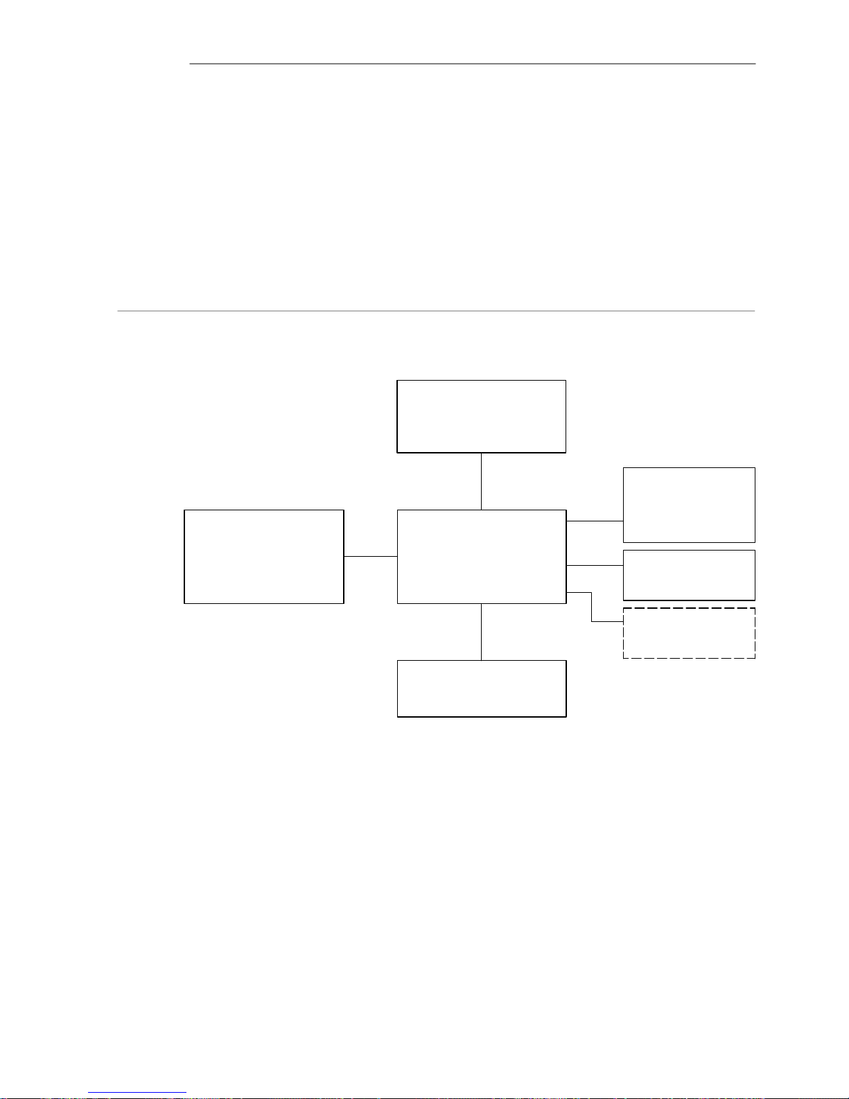
Service Manual Chapter 5 - Functional description
Battery Charger CS0074
5 - 53x3 UPS Functional description
Issue 2 - November 2001
5.4.3 - Battery test
The battery test circuit will automatically initiate at the time interval selected by the links J4, J5 and J6.
The test duration is set at 10 seconds, during this period the battery charger logic switches off the mains
power by opening the input test relay K1 which shuts down the charger circuit. The terminal voltage of
the battery is then monitored to verify the battery status, if this is correct and stable over a 20 seconds
period, the battery charger will restart and continue to charge the battery.
If the battery check fails detecting a parameters different from the expected value, the control logic initiĆ
ates a battery fault alarm. The fault will give a flashing red LED on the front mimic panel. If the battery
test is satisfactory the green battery LED will illuminate indicating that the battery is OK.
5.5 - UPS monitor board PCB CS0077
The function of UPS monitor board is to interface the UPS control and status alarm signals with the OperĆ
ator LCD Control panel Part Nº CS0075 , the Relay Interface PCB Part Nº CS0082 and the SNMP
adapter.
SNMP CARD
UPS CONTROL LOGIC
P/N CS0072
LCD MIMIC
DISPLAY
P/N CS0075
UPS MONITOR
BOARD CS0077
Inverter Driver &
Feedback
CS0071
RELAY
INTERFACE
P/N CS0082
OPTIONAL RELAY
INTERFACE
P/N CS0082
J1
J7
J6
J2
J3
J5
This board has a microprocessor that manage and control the serial port, the SNMP adapter, the LCD
messages and UPS menu.
The LCD Display Panel displays textual messages and operating parameters on a LCD screen capable
of showing 4 rows of 20 characters.
The displayed screen is organized in a multi-level menu system and selected by using push button
located to the right of the screen.
LD1 illuminated indicates that the monitor board is failed and must be replaced.
BT2 is an hardware and software reset.
Links setting:
JP1 1-2 close and JP3 2-3 close are factory setting.
JP2 close disable the second remote EPO, JP2 open enable the second remote EPO.

Service ManualChapter 5 - Functional description
Relay Interface PCB CS0082
5 - 63x3 UPS Functional description
Issue 2 - November 2001
5.6 - Relay Interface PCB CS0082
The relay interface PCB provides two sets of volt free contacts rated at 50V 1A which enable the UPS
functions listed below in Table 5-1 to be monitored externally. The relay interface PCB receives the UPS
status signals from the Display Control Logic PCB Part Nº CS0073 and is connected to CN1.
Output signals from the relay interface are used for the control of customer peripheral computer equipĆ
ment and connections are made to the terminal block M1 shown in Figure 5Ć2, or from the RS232 DB9
connector P1 (fitted to later equipment only).
Table 5-1 Relay Interface PCB Output
Link
Relay UPS Function Signal Function
JP4 JP5
Mains NOT OK Closed Open
RL1 MAINS STATUS
Mains OK Open Closed
RL2 BYĆPASS ON
RL3 UPS Ć RUN
No associated link
RL4
PREĆALARM
No associated link
Links fitted to the PCB allow the input mains status to be set and the serial port P1 to be enabled as shown
in Table 5-2. These signals are generated on the display control logic PCB and connected to the relay
PCB at connector CN4.
Table 5-2 Serial Port P1 DB9 Connector Connections
Pin
Link
Pin
Nº
Function Relay
JP1 JP2 JP3 JP4 JP5
5 COMMON N/A Closed ć ć
3 UPS RX N/A ć Closed ć
ć
2 UPS TX N/A ć ć Closed
89MAINS
STATUS
RL1 ć
MainsĆ
NOK
MainsĆOK
1
7
PRE ALARM RL4 ć
5.6.1 - EPO Connections.
Provision has been made on the relay interface PCB to connect an external `Emergency Power Off'
switch, to allow remote shut down of the UPS to be implemented.
Connection for the EPO is provided by the terminal block M2.
Caution When connecting an EPO switch to the relay PCB the Link JP6 must be opened.
5.6.2 - Optional Second Relay Interface PCB
If a second set of outputs is required, an optional relay interface PCB can be connected to CN3 on the
display control logic PCB.
Caution With two relay PCB's connected. Link JP1 on the display logic PCB must be opened in
addition to JP6 on the optional relay PCB, to allow the use of a Second EPO switch.

Service Manual Chapter 5 - Functional description
Relay Interface PCB CS0082
5 - 73x3 UPS Functional description
Issue 2 - November 2001
Figure 5-1 Relay Interface Outputs
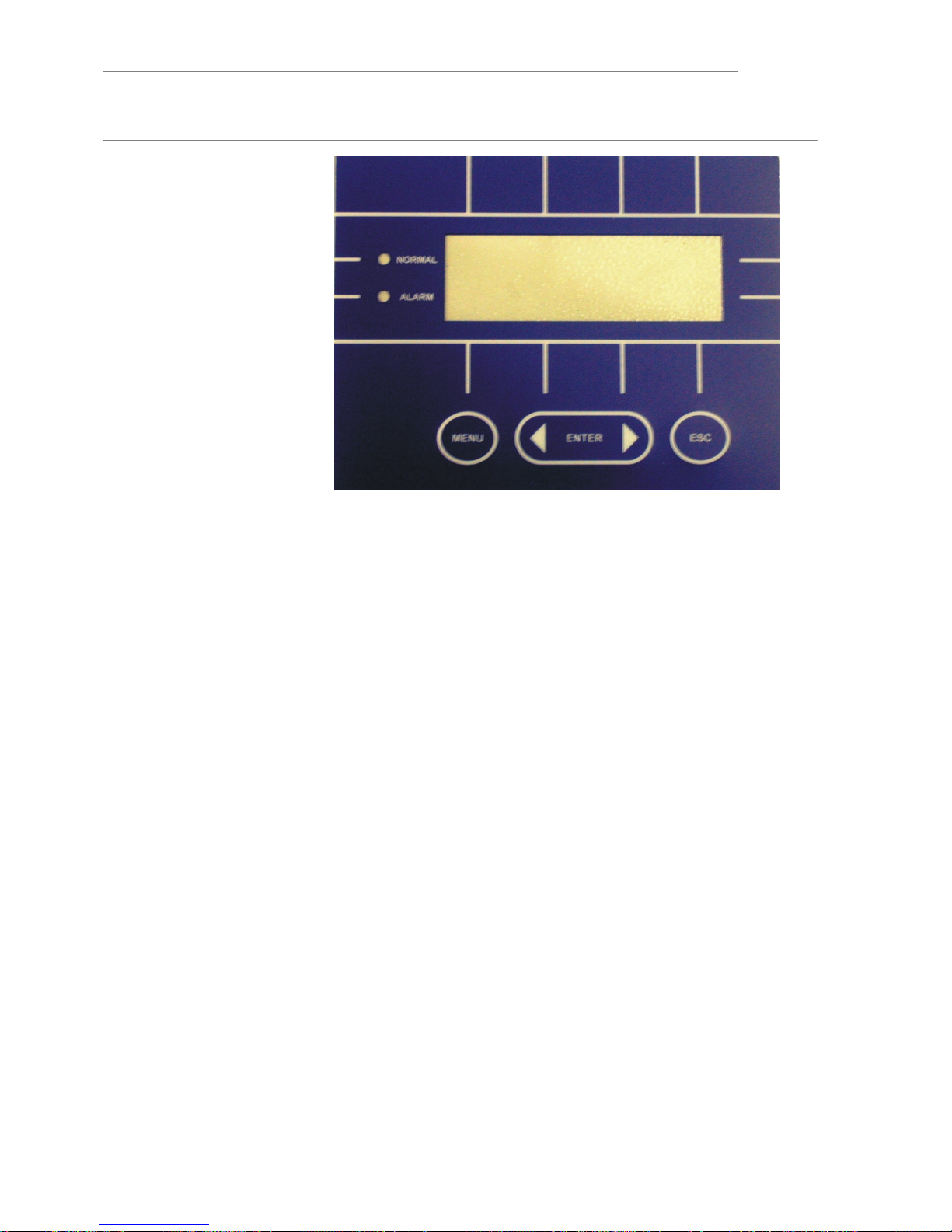
Service ManualChapter 5 - Functional description
Relay Interface PCB CS0082
5 - 83x3 UPS Functional description
Issue 2 - November 2001
5.7 - LCD MIMIC DISPLAY CS0075
LCD control panel
5.7.1 - Control panel indicator LEDs
The menu contains three levels. The main level is the State and Alarm Menu.
In this menu it is possible to see the state and operative condition of the UPS, the CLEAR Button is used
to scroll through the different windows of this menu.
From the main menu the User may have access to different menu pressing the MENU Button (second
level).
Once in this level the first row will show < menu choice > and the NEXT and BACK push Button enable
the User to move from one menu level to another.
Pressing both NEXT and BACK push button at the same time the ENTER command is selected and the
next lower level will be reached, while CLEAR take you back to the previous level. To verify the acquisition
of ENTER a Beep will be heard and CONFIRMED will appeared on the Display.
The NEXT/BACK selector keys are used to scroll through different windows in the same menu.
(See Chapter 4)

Safety
Precautions
6 - 13x3 UPS Maintenance
Issue 2 - November 2001
Chapter 6 - Maintenance
This section contains the procedures necessary to effect general maintenance of the UPS and battery.
Certain procedures entail gaining internal access to the UPS, and should be undertaken only by a comĆ
petent engineer who is familiar with the operation and layout of the equipment and is fully conversant
with the areas of potential hazard. If there are any doubts concerning safety, or the method of carrying
out any procedure then contact an approved service agent for assistance or advice.
The equipment contains live voltages at ALL Swiss unless externally isolated from the mains
supply, bypass supply and batteries.
When working on the UPS it is essential that the safety and precautionary notes in this manĆ
ual are read and FULLY UNDERSTOOD before touching any UPS internal component part.
6.1 - Scheduled Maintenance
The UPS utilises solidĆstate components not subjected to wear, with the only moving part the cooling
fan. Scheduled maintenance requirements, beyond ensuring that the environmental conditions remain
suitably cool and clean, are therefore minimal. However, a well documented periodic program of inspecĆ
tion and preventive maintenance, as suggested below; will ensure optimum equipment performance
and serve to detect minor malfunctions prior to them developing into a major fault.
6.1.1 - Daily Checks
Carry out a daily walkĆby inspection of the UPS, checking the following points:
1. Carry out a spot check of the Operator Control Panel; ensuring that all mimic LED
indications are normal and no alarm messages are present.
2. Check for obvious signs of overheating.
3. Check for continuous exit air flow from the extractor fans on the front door.
4. Ensure that the ventilation grills around the UPS are unobstructed.
5. If possible, log the results of the inspection, noting any discrepancies from the norm.
6.1.2 - Weekly Checks
Perform the following checks and log the results:
1. Measure and record the battery charge voltage.
2. Measure and record the battery charge current.
3. Measure and record the UPS output voltage on all three phases.
4. Measure and record the UPS output line currents.
If there are significant differences from the values previously recorded, note the size, type and location
of any additional load connected to the UPS supply since the previous inspection. This type of informaĆ
tion could prove useful to the troubleshooting engineer should a problem occur.
If any of the above indications differ greatly from the previously logged values for no apparent reason
you should contact the Customer Service & Support Department at the address given at the front of this
manual for advice.

Service ManualChapter 6 - Maintenance
Scheduled Maintenance
6 - 23x3 UPS Maintenance
Issue 2 - November 2001
6.1.3 - Annual Maintenance
Caution We strongly recommend that the annual maintenance is carried out by a manufacturerĆ
trained engineer who is fully aware of the hazards concerned and will carry out this proĆ
cedure, where necessary with the load connected to the maintenance bypass supply
WARNING LETHAL VOLTAGES ARE PRESENT IN THE UPS UNIT EVEN IF THE UNIT HAS BEEN
SWITCHED OFF AND ISOLATED
The following procedure is intended as a guide to carrying out an annual preventative maintenance
schedule. It is assumed that the engineer carrying out this procedure has been trained in the operation
of the UPS and is able to operate the unit in the `Maintenance Mode'.
Preliminary checks
1. Visually inspect the outside of the UPS and determine that the operating environment is
correct.
2. Carry out the checks detailed in `Weekly Checks'.
3. Determine if any abnormal faults have been previously recorded.
4. Confirm with the load user that it is safe to transfer the unit to maintenance bypass before
proceeding.
Transfer to the Maintenance Bypass
The manual bypass allows the UPS to be switched OFF while the critical load is maintained.
To transfer the load to Maintenance Bypass:
1. Press the `MENU' push button ( A ) on the FRONT PANEL.
a) Select the `COMMAND' screen by pressing either the `BACK' ( C ) or `NEXT' ( b ) push
button.
b) Confirm the `COMMAND' menu selection by pressing `BACK' and `NEXT' at the same
time (i.e. ENTER).
c) Select the `SWITCH LOAD' function by pressing either `BACK' or `NEXT'.
d) Confirm `SWITCH LOAD' function by pressing `BACK' and `NEXT' at the same time.
D A ***CONFIRMED*** message will be displayed
2. Press `CLEAR' ( d ) twice to return to the main menu.
The following change-over sequence should occur, indicating that the load has been transfer to the
bypass line:
D The yellow `BYPASS ON' LED ( 4 ) is illuminated
D The green `LOAD on INV' LED is extinguished.
3. To turn off the Inverter follow the procedure below:
a) Press the `MENU' push button ( A ) on the FRONT PANEL.
b) Select the `COMMAND' screen by pressing either the `BACK' ( C ) or `NEXT' ( b ) push
button.
c) Confirm the `COMMAND' menu selection by pressing `BACK' and `NEXT' at the same
time (i.e. ENTER).
d) Select the `INVERTER ON-OFF' screen by pressing either the `BACK' ( C ) or `NEXT' (B)
push button.
e) Confirm `INVERTER OFF' function by pressing `BACK' and `NEXT' at the same time.
D A ***CONFIRMED*** message will be displayed
f) Press `CLEAR' twice to return at the main screen.
4. The follow sequence should occur:
D The Alarm buzzer is activated.
D The Red general `ALARM' red LED ( 2 ) will illuminate.

Service Manual Chapter 6 - Maintenance
Scheduled Maintenance
6 - 33x3 UPS Maintenance
Issue 2 - November 2001
D The Yellow `BYPASS ON' LED ( 4 ) will illuminate.
D The Green `NORMAL' LED will extinguish.
D The LCD will display the following messages:
`LOAD ON BYPASS' and
`INVERTER OFF'.
5. Remove the Mechanical Lock from the MANUAL BYPASS MCB ( I3 )
6. Close the. MANUAL BYPASS MCB ( I3 )
7. Open the `UPS OUTPUT' MCB ( I4 ).
8. Open the `MAINS INPUT' MCB ( I1 ).
9. Open the `RESERVE INPUT' MCB ( I2 ).
10. Open the `INTERNAL BATTERY' fused switch ( I5 ).
11. Check that the load continues to be powered from the Maintenance Bypass Mains supply
while the UPS is off.
12. Wait a minimum of 10 minutes before proceeding to allow the DC bus voltage to discharge.
WARNING THE DC BUS VOLTAGE OF 750VDC MAY TAKE SEVERAL MINUTES TO DISCHARGE TO A
SAFE LEVEL.
13. Remove the top cover of the UPS to gain internal access to the unit.
RETURN FROM MANUAL BYPASS TO NORMAL OPERATION
The following procedure describe how to start the ups and transfer the load from the maintenance byĆ
pass to the ups inverter.
1. Close the `RESERVE INPUT' MCB. ( I2 )
D wait until the fan is running, indicating that the output voltage is present.
2. Close the `MAINS INPUT' MCB. ( I1)
Wait until the Operator panel shows the following indications:
D LCD is energize and
D The alarm buzzer sounds.
D The red `ALARM'LED ( 2 )
D The yellow `BYPASS ON' LED will illuminate.
3. Close the `INTERNAL BATTERY' fused switch. ( I5 ).
4. Close the `UPS OUTPUT' MCB. ( I4 ).
5. Open the `MANUAL BYPASS' MCB. ( I3 ).
6. Start the inverter as follow:
a) Press the `MENU' push button ( A ) on the FRONT PANEL.
b) Select the `COMMAND' screen by pressing either the `BACK' ( C ) or `NEXT' ( b ) push
button.
c) Confirm the `COMMAND' menu selection by pressing `BACK' and `NEXT' at the same
time (i.e. ENTER).
d) Select the `INVERTER ON- OFF' screen by pressing either the `BACK' ( C ) or `NEXT' (
b ) push button.
e) Confirm `INVERTER ON' function by pressing `BACK' and `NEXT' at the same time.
D A ***CONFIRMED*** message will be displayed
f) Press `CLEAR' ( d ) twice to return at the main screen.
7. Within approximately 20 sec. and the follow sequence should occur:
D The green `NORMAL' LED ( 1 ) has illuminated.
D The red `ALARM' LED ( 2 ) has extinguished.
D The yellow `BYPASS ON' LED ( 4 ) has extinguished.
D The green `LOAD-on-INV' LED ( 3 ) has illuminated.
Place the mechanical lock, onto the `MANUAL BYPASS' MCB.
The UPS is now in the normal operating condition with the Inverter supplying the load.

Service ManualChapter 6 - Maintenance
Scheduled Maintenance
6 - 43x3 UPS Maintenance
Issue 2 - November 2001
Mechanical inspection
1. Carry out the weekly checks detailed above
2. Ensure that the UPS is totally powered down.
a) Check for input AC voltage at the rectifier input connections SKD 82/12 terminals 14, 15
& 16
b) Check for Battery voltage at the battery connection terminals 6 & 7 ćve, 8 & 9 +ve.
c) Check for AC voltage at the output terminal connections 2, 3 & 4.
d) Check for an AC voltage at the Reserve Bypass input terminal connections 10, 11 & 12.
Note: Refer to Figure 2Ć1 on page 2Ć4 for terminal connection detail.
3. Gain access to the UPS interior by removing the top cover panel.
4. Carry out a thorough examination of the UPS power components and subĆassemblies,
paying particular attention to the following:
a) Electrolytic capacitors Ċ check for signs of leakage, distortion etc.
b) Magnetic components Ċ check for signs of overheating, security of fixture and
deĆlamination.
c) Cables and connections Ċ check cables for signs of overheating.
d) Check that all printed circuit board connectors are secure.
e) Printed circuit boards Ċ check the cleanliness and integrity of the PCB's and replace if
any signs of deterioration are found.
5. Thoroughly clean inside the equipment enclosure using a vacuum cleaner and low pressure
air to remove any foreign debris.
6. Reconnect the UPS input mains power.
Power checks
1. Start the UPS following the appropriate operating procedure.
2. Carry out a calibration of the DC Bus Voltage and Inverter output voltage.
3. Connect a DVM set to DC volts to the DC bus and a second DVM set to AC volts to the UPS
output.
4. Select I1 (Input mains) to ON
a) The DC voltage will increase slowly up to 650 Vdc.
b) After 10 sec. the converter and the inverter will start regulating respectively
The DC Bus voltage to 750 Vdc ± 1%
The output inverter voltage to 400 Vac ± 1% (Assuming the UPS is set for an output of
400 Vac)
5. If the measured values are incorrect, reĆadjustment of the voltage settings can be carried out
using the potentiometers on the UPS control logic PCB Part Nº CS0072.
Note: Turning P1 Inverter feedback potentiometer CCW will increase the
voltage.
Turning P2 Converter feedback potentiometer CCW will increase the
voltage.

Service Manual Chapter 6 - Maintenance
Scheduled Maintenance
6 - 53x3 UPS Maintenance
Issue 2 - November 2001
Table 6-1 Output Voltage PCB Link Settings
Link
PCB Part Nº 38OVac 400Vac 4l5Vac
J4 CS0072 open close open
J5 CS0072 close open open
JIA CSOO7I close open open
J2A CSOQ7I open close open
J3A CSOO71 open open close
lnverter Bypass Phase Lock check
1. Using a dual trace oscilloscope operating in the differential mode (insulated from mains) on
the inverter driver interface PCB (CSOO7I) connect:
a) Probe 1 to the bypass `R' phase voltage terminal stud N9.
b) Probe 2 to the inverter output phase `R' voltage terminal stud N 7.
2. Check both sine waves are perfectly in phase.
The phase adjustment is fixed and is determined by R23 on the driver interface CSOO7I (1
Mohm).
The check of the CONVERTER and INVERTER section is now complete.
Battery charger checks
Float voltage adjustment and battery reĆcharging current
1. Connect a DVM set to DC volts to the battery DC bus terminal connecting block (terminal 6Ć7
positive, 8Ć9 negative).
2. Open the battery power fuses F1 to F4.
3. Check that the value at the battery DC bus terminal connections is 432 Vdc ± 1%.
If the measured value is different it is possible to reĆadjust using the potentiometer P1 on the
battery charger PCB C50074.Ć
Note: Turning P1 CCW will increase the float voltage
4. Refit the battery fuses.
5. Check the battery reĆcharging current with a DC clamp meter.

Service ManualChapter 6 - Maintenance
Battery Maintenance
6 - 6UPS Maintenance
Issue 2 - November 2001
6.2 - Battery Maintenance
The batteries fitted within the UPS are valve regulated and require very little maintenance.
It is wrong to describe them as completely `maintenance free', because the batteries still require a mainĆ
tenance check, but at a significantly greater interval than the unsealed type.
The removal of the need to continually top up batteries, is a major advantage, but by removing access,
a visual examination of the cell plates, and electrolyte is impossible.
Battery condition and capacity can therefore only be determined as a complete 12V battery block.
The battery is an important component in the UPS system, as the UPS function relies on the battery
power, on failure of the input AC supply To ensure that the battery will support the UPS operation it should
be checked annually for performance.
6.2.1 - Factors Effecting Battery Use
The following factors affect the overall operation and ultimately the useful life of the UPS battery. These
considerations must be taken into account when deciding the serviceability of a battery.
Service life
Temperature is the major factor in determining the effective life of a battery if the battery is operating
above 200 C it will reduce the battery life. It is also important that the charge voltage is within limits. TypiĆ
cally a 5 year life battery will start to decline after 3 years in service, therefore the need for regular checks
is important.
Charge voltage
The nominal charge voltage is normally 2.25 volts per cell, multiplied by the number of cells in series.
Operation at voltages below 2.2 volts per cell, will lead to a undercharge and sulphation. Operation at
2.3 volts per cell and above, will cause overcharge and rapid positive plate corrosion. Positive plate corĆ
rosion is known to be the major life limiting component in all batteries, therefore for optimum life, battery
cell voltages must be within the range of 2.25 to 2.3 volts per cell.
The UPS has 32 x 12V batteries and is designed to operate with a float charge voltage of 432 V
DC.
Battery capacity
Battery capacity is used to define endĆofĆlife of the battery for example if the battery cannot supply 80%
it is deemed to be at the end of its effective life. For some applications 80% may be decreased to 50%
to mark the end of the batteries effective life.
Battery capacity from manufacture, usually increases slightly after 2 or 3 discharges and will be enĆ
hanced by high temperature and reduced by low temperature.
As the battery ages beyond 12 months the battery capacity will fall at a rate determined by the operating
temperature and the charge voltage. These adverse factors, will cause accelerate erosion to the positive
plate grid, reducing the effective battery capacity The life of the battery will then depend on the requireĆ
ments of the system, if the capacity of the UPS has been oversized then the load may only need 50%
of the normal duty.
In most applications, the battery is essentially on continuous float charge, and rarely will experience a
input supply failure longer than the end of the battery autonomy.
Therefore a battery in poor condition may well continue to support the load for short autonomies, but
will fail if the loss of the input AC supply exceeds 30 seconds.
It is therefore highly recommended that a battery autonomy test, is carried out as part of a regular mainĆ
tenance program.
Open circuit voltages
Measurement of the battery open circuit voltage is not a good indicator of the available capacity of the
battery It may apply to batteries on the shelf but not to batteries that have been on charge, up to 72 hours
prior to measurement. The terminal voltage of batteries that have been on charge, have an actual cell
voltage, plus a polarization voltage.

Service Manual Chapter 6 - Maintenance
Battery Maintenance
6 - 73x3 UPS Maintenance
Issue 2 - November 2001
The polarization voltage will disappear once loaded, but can lead to misleading terminal voltage
measurements.
To use the open circuit voltage of a battery as a guide to its capacity it must have been disconnected
for at least 72 hours. This measurement is taken off load and can only be used as a guide, it will not indiĆ
cate a battery with high internal resistance.
Float voltage
The float voltage of each battery connected in a series string, is determined by its impedance, relative
to other batteries. The voltage measured at each battery while on charge can give an indication to its
serviceability A battery on charge taking above the minimum float current, will have a different voltage
distribution to one that is fully charged. This measurement can therefore give an indication of the charge
of the battery however a valid voltage reading can only be obtained if the battery has been on float
charge for at least 48 hours.
For maintenance purposes, the ideal is to check the float voltage of each battery before shutting the UPS
down, if the test is carried out after shut down, the reading will not be valid until the float current normalĆ
izes back to its original level, prior to shut down.
It is recommended that a float voltage check is carried out on the unit if a battery problem is suspected,
a defective battery will normally give an abnormal terminal voltage.
6.2.2 - Battery Testing
When working on batteries, regardless of size, remember they have considerable energy content under
short circuit conditions.
They cannot be switched off or isolated as is normal in electric circuits.
WARNING RISK OF DEATH, SHOCK OR BURN. WHEN THIS BATTERY IS ASSEMBLED, IT IS A SOURCE
OF 390 VOLTS.
Caution Use extreme care to ensure that batteries are not accidentally short circuited by tools, rings,
watch straps etc.
Use insulated hand tools.
Wear eye protection during handling of batteries.
Before tightening or making connections on battery strings, ensure the battery is isolated
from the UPS circuit and is earth free.
In the event of a battery breakage occurring, dispose of in a container resistant to sulphuric
acid.
Should electrolyte contact the skin, wash the affected area immediately
Site testing
It is not normally possible to check the float voltage of the battery string prior to turning the UPS off, but
the float voltage may need to be checked subsequently.
Float voltage test
Batteries on float below 13.0 V per I2V battery will ultimately sulphate.
Batteries above 13.8 V will have a short service life, and indicates a deteriorating cell.
Investigate the serviceability of batteries with a float voltage below 13.4 V and above 13.98 V If the averĆ
age float voltage is at the correct level, check and replace if necessary any batteries that fall outside the
float voltage parameters.
Visual examination
1. After shutdown examine the batteries for the following:

Service ManualChapter 6 - Maintenance
Battery Maintenance
6 - 83x3 UPS Maintenance
Issue 2 - November 2001
a) White deposits around the terminal seals which indicate seal failure.
Replace any batteries found.
2. Check the security of the terminal connections. Examine for signs of corrosion or
overheating.
3. Inspect battery cases for distortion, splits or bulges.
a) Batteries near the end of their effective life, will exhibit bulges in the case, due to
increasing pressure of the positive plates as they grow in size.
b) Severe distortion may also be apparent, caused by the higher resistance of the corroded
plates, which tends to generate heat during charge and discharge. In turn the plastic of
the case will creep and failure of a single cell will cause the side of that cell to bulge.
c) Total end of life condition will normally cause all cells to bulge or distort.
6.2.3 - Battery capacity testing.
There are generally two ways in which the capacity of a battery can be tested by impedance measureĆ
ment, or by load testing.
Impedance measurement
Measurement of the battery AC impedance requires special test equipment, but gives a measure of how
the battery impedance has changed since new. Any battery that has been on continuous float charge
prior to the test, should not exhibit more than twice the new battery value.
Values in excess of this, indicate the battery is nearing the end of its effective life, while batteries exhibitĆ
ing 4 or more Swiss the new value, need immediate replacement.
This test will only look at the battery level and not the individual cell level, therefore, a cell with above
normal impedance to the others, will not be indicated.
Discharge test
The more common method of determining the capacity and serviceability of the batteries, is to carry out
a discharge test.
A suitable resistor designed to draw a current equal to the Ah size of the battery is placed across the
battery terminals. The battery terminal voltage is then monitored.
A fairly large wattage, 5 W resistor capable of taking 11A is connected across the battery terminals. After
10 minutes discharge, the battery terminal voltage should not fall below 11.2 V indicating the 50% capacĆ
ity level.
If a battery has high internal resistance and reduced capacity the terminal voltage will fall quickly.
Batteries with a capacity above 50% may continue to be used, but will reduce the autonomy of the sysĆ
tem. It is recommended that they be replaced, however batteries below 50%, should always be reĆ
placed.
Note: A higher resistance value, discharge resistor may be used to discharge
the battery. The terminal voltage measured will then give an indication of
the serviceability of the battery, but is not an accurate measure of the
battery capacity.

Service Manual Chapter 6 - Maintenance
Battery Replacement
6 - 93x3 UPS Maintenance
Issue 2 - November 2001
6.3 - Battery Replacement
When deciding to replace a battery the following must be considered, and a decision taken, to mix old
or new batteries in the series string. Adding new batteries to a series string that has been in use for more
than 18 months, may induce problems due to the difference in capacity A new undercharged battery
placed into a fully charged old string, may fail to achieve full charge. The other batteries in the string may
limit the charge current, as the older batteries may only require a charge current of some milliamps, this
may then cause the new battery to sulphate. If a new battery is fully charged before inclusion, the probĆ
lem should not arise, however the effective life of the new battery is limited to that of the originals. The
new battery may also have a higher terminal float voltage.
Replacing more than one battery may cause redistribution of the float voltages, causing over and underĆ
charging. Attempts to equalize the string by using a top charge of 2.4 volt per cell, may cause temporary
overheating and the test should only be carried out with continual monitoring.
Applying a top charge, (equalization) to a battery of unknown quality can lead to rapid overheating and
the possible release of acid fumes. Equalization on a long series string has not shown to be of any beneĆ
fit, due to the ability of the batteries to absorb the excess charge over a large number of cells. However~
equalization of a single battery introduced into a string, is effective.
Since a site visits to replace a single battery is a costly process, a point will be reached where it is more
cost effective to replace an entire battery string than to properly asses the battery condition, and carry
out single or multiple replacements. This decision has the additional advantage of enhancing the reliaĆ
bility of the system, and has the benefit of a 12 month warranty on the new battery.
6.4 - UPS Storage
If the UPS is to be transported, or stored in a powered down condition for any length of time, the internal
battery may discharge below the minimum battery voltage.
To prevent this condition occurring, remove the battery fuses and retain with the unit.
For periods of storage in excess of 12 weeks, the batteries will exceed their shelf life.
This can be prevented by operating the UPS and allowing them to reĆcharge for 24 hours.
Battery recharging is done by:
1. Connect the UPS to an input AC supply
2. Fit the battery fuses.
3. Power up the UPS and allow it to operate for 24 hours.


7 - 13x3 UPS Troubleshooting
Issue 2 - November 2001
Chapter 7 - Troubleshooting
7.1 - Introduction
The UPS contain complex electronic control circuits which require a firm understanding,
in order to carry out comprehensive fault diagnosis and repair of the equipment. The aim of the informaĆ
tion contained in this chapter is to provide sufficient guidance to the trained service engineer, to enable
successful fault location to printed circuit board level. Once a faulty circuit board or component has been
identified, it should be replaced or returned to the nearest service centre for repair.
The troubleshooting information has been divided into the following main areas:
a) Component location and identification.
b) Diagnostic information.
c) Troubleshooting procedures.
d) Test procedures.
Note: When following the procedures cross referencing is inevitable, therefore
it is recommended that this chapter is read in its' entirety, before
commencing work on the equipment.
There is no practical way of detecting an impending UPS malfunction, as most problems do not emerge
as a gradual performance degradation. Generally the UPS will either work correctly or shut down with
or without a warning indication.
In the event of a UPS malfunction troubleshooting should be carried out methodically along the following
guide lines.
7.1.1 - General Fault Identification Procedure
When first summoned to a UPS fault the immediate action should be to observe and record the LED
indication displayed on the unit operator panel.
1. Determine the UPS power Status.
2. Note the control switch configuration, and also the warning horn sequence if it is operating.
WARNING During troubleshooting it will be necessary to power up the unit with the side or top covers
removed, in this situation exposure to potentially lethal voltages is possible even with the
input utility supply switched off.
Take great care at all Swiss to minimise the risk of contact with live voltages, especially when
working around the battery or the DC bus.
3. Power down the unit, and ensure that the DC Bus Safety discharge check is carried out.
4. Gain access to the internal components follow the procedure for removing the UPS covers.
5. Check the serviceability of the UPS Fuses refer to the check list on page 7Ć12.
6. Apply power and analyse PCB LED indications.
7. Refer to the common fault identification chart on page 7Ć9 to identify possible fault
conditions.
8. Check DC converter power components. Refer to the procedures on page 7Ć19.
9. Check Inverter power components. Refer to the procedure on page 7Ć19.
Note: When checking signal levels refer to the table of typical normal values on
page 7Ć11 for comparison.

Service ManualChapter 7 - Troubleshooting
Special Tools
7 - 2 3x3 UPS Troubleshooting
Issue 2 - November 2001
7.2 - Special Tools.
No special tools are required to service the UPS, a normal electricians tool kit will be adequate.
However, to carry out the check procedures contained in this chapter the following test equipment will
be required.
Oscilloscope.
A dual beam oscilloscope, which has the ability to sum the two channels, allowing differential voltage
measurements to be made.
For the measures points that it is needed to check it is very important to have the oscilloscope insulated
from the supply with a transformer.
A storage facility is useful but not essential.
WARNING ENSURE THAT ANY OSCILLOSCOPE USED IS RATED FOR USE ON 1000 V AND IS FITTED
WITH APROPRIATE 1000 V LEADS AND TEST PROBES.
Digital volt meter (DVM).
The voltages quoted in this manual assume that a true RMS reading AC voltmeter is used. A meter that
also has the ability to test electronic components such as diode's and similar electronic devices is reĆ
quired.
WARNING ENSURE THAT ANY DVM USED IS RATED FOR USE ON 1000 V AND IS FITTED WITH
APROPRIATE 1000 V LEADS AND TEST PROBES.

Service Manual Chapter 7 - Troubleshooting
Removing the UPS Covers
7 - 33x3 UPS Troubleshooting
Issue 2 - November 2001
7.3 - Removing the UPS Covers
To gain access to the UPS components the following covers must first be removed.
Figure 7-1 UPS Cover Removal
Battery Safety Cover
Covers Removed
Main Switch Cover
Top Heatsink Cover
Top Cover
Right Side Cover
Lockable Front Door
1. Front Door Panel
a) To gain access to the power switches and battery compartment the front door panel is
first unlocked and hinged forward.
2. Battery Safety Cover
a) Disconnect the Earth bonding cable.
b) Remove the two top M6 retaining bolts.
c) Release the two bottom retaining bolts and lift the cover from the UPS.
Note: The battery safety cover has slots on the lower edge for easy removal and
repositioning.
3. Main Switch Cover
a) Remove the four M6 retaining bolts.
b) Carefully ease the cover away from the control switches.
4. Heatsink Cover
a) Remove the four M6 retaining bolts.
a) Carefully ease the cover away from the front of the UPS.
5. Top Cover.
WARNING DANGER OF SEVERE SHOCK OR BURNS. 800V DC IS EXPOSED WHEN TOP COVER IS
REMOVED DO NOT REMOVE THE COVER UNLESS THE UPS HAS BEEN COMPLETELY
POWERED DOWN AND THE DC BUS ALLOWED TO DISCHARGE FOR 10 MINITUES

Service ManualChapter 7 - Troubleshooting
Removing the UPS Covers
7 - 43x3 UPS Troubleshooting
Issue 2 - November 2001
a) Ensure that the UPS has been correctly switched off and the battery fuse switches are
opened.
b) Wait for at least 10 minutes to allow the DC bus to fully discharge.
a) Carefully lift the cover from the retaining ball studs.
6. Side Panels
a) Remove the three M6 retaining screws securing each side panel at the rear of the UPS.
b) Disconnect the earth cable fitted to the top rear of each side panel, from the UPS chassis
by removing the M6 earthing bolt.
c) Push the panel forward to disengage the front locating studs and lift the panel from the
UPS.
Rear Cover Removal
7. Power Distribution Terminal Block Cover.
a) Remove the six M6 retaining screws from the terminal block cover and lift from the UPS.
Refer to Figure 7Ć2.
Figure 7-2 Rear Cover Removal
Rear Covers Fitted
Distribution Terminal Block Cover
Removed
Side Cover
Retaining Bolts
Rear Side Cover Earth Cables
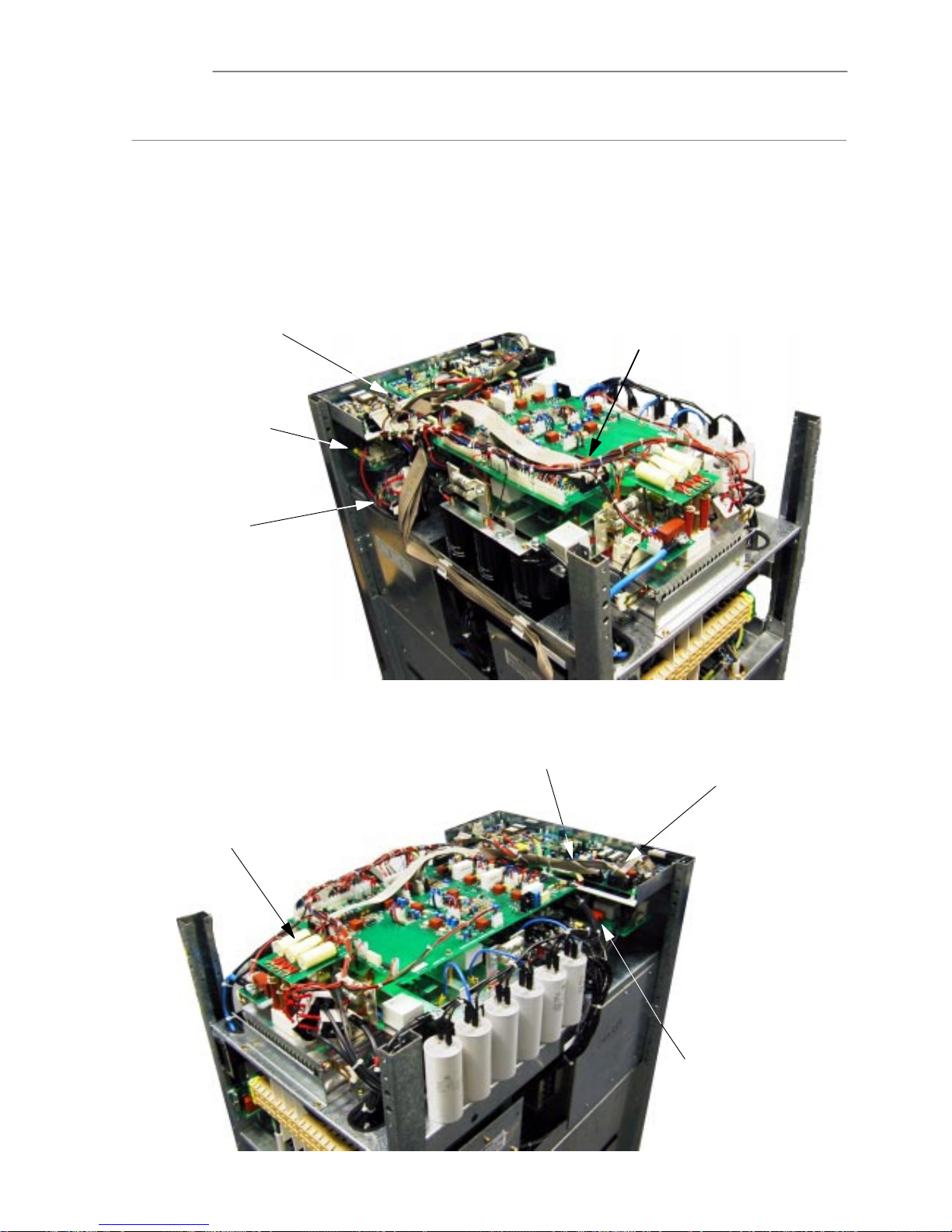
Service Manual Chapter 7 - Troubleshooting
Component Location
7 - 53x3 UPS Troubleshooting
Issue 2 - November 2001
7.4 - Component Location
Before starting to repair or service the UPS models, correct identification of the main compoĆ
nents and their location is required. All the main power component are mounted on the power heatsink
under the driver interface board.
The following information is primarily to furnish the repair engineer with a quick reference to the basic
component identification and location. A detailed breakdown of the equipment components and spare
parts kits available can be found in Chapter 9 Spare Parts.
Figure 7-3 Main PCB Location
3Ph TL Control Logic PCB
Part Nº 0SDE0072
Battery Charger PCB
Part Nº 0SDE0074
Inverter Driver/Feedback PCB
Part Nº 0SDE0071
Input Filter PCB
Part Nº 0SDE0079
Fan PCB
Part Nº 0SDE0078
Auxiliary DCĆDC Converter PCB
Part Nº 0SDE0070
UPS Monitor PCB
Part Nº 0SDE0077
Battery Charger PCB
Part Nº 0SDE0074

Service ManualChapter 7 - Troubleshooting
Component Location
7 - 63x3 UPS Troubleshooting
Issue 2 - November 2001
Figure 7-4 Semiconductor Components
Inverter SCR's (x 3)
91A (S1 S3 S5)
Part Nº 0CASR212391
Inverter IGBT's 150A
150A (Q1 Q2 Q3)
Part Nº 0CATRCM150BU24F
Transfer Diode
60A (CD1)
Part Nº 0CSDRFBYT261P12
Snubber Diodes
30A (CD4 CD5)
Part Nº 0CADR210230
Converter IGBT
200A (Q4)
Part Nº 0CATD212420
Input Bridge (PD1)
Part Nº 0CADTSSKD82/12
Input SCR
132A (S7)
Part Nº 0CSSX212413
Bypass SCR's (3)
91A (S2 S4 S6)
Part Nº 0CASR212391
Transfer Diode
60A (CD2)
Part Nº 0CSDRFBYT261P12
Snubber Diode
30A (CD3)
Part Nº 0CADRFBYT231
Input SCR
132A (S8)
Part Nº 0CSSX212413

Service Manual Chapter 7 - Troubleshooting
Component Location
7 - 7UPS Troubleshooting
Issue 2 - November 2001
Figure 7-5 Passive components
Thermostat
55oC (ST2)
Part Nº 0CEX50CLSD
Thermostat
85oC (ST1)
Part Nº 0CEX-SONDA
Inverter CT's
1/1000 (TA1 TA2 TA3)
Part Nº 0CEMC316610M019
Inv Snubber Capacitors
2.5ìF (C9 C10)
Part Nº 0CPCPP525850
Capacitor
5ìF (C5)
Part Nº 0CPCPP505700
Sec. DC Bus Filter Caps
4400ìF (x 3 of 6)
Part Nº 0CPA08440400
DC Bus Fuse
125A (F3)
Part Nº 0CEFXV412
Capacitor
0.47ìF (C4 C3)
Part Nº 0CPCPP4471200
Primary DC Bus Fuse
125A (F1)
Part Nº 0CEFXV412
Output Filter Caps (x 6)
60ìF (C1 C2 C3 C4 C5 C6)
Pt. Nº 0CPCPA06600450
Capacitor
15ìF (C7)
Part Nº 0CPCPP615400
Capacitor
15ìF (C8)
Part Nº 0CPCPP615400
DC Bus Fuse
125A (F3)
Part Nº 0CEFXV412
Primary DC Bus Cap
15ìF (C1)
Part Nº 0CPCPP615400
Primary DC Bus Fuse
125A (F4)
Part Nº 0CEFXV412
Primary DC Bus Cap
15ìF (C2)
Part Nº 0CPCPP615400
Sec. DC Bus Filter Caps
4400ìF (x 3 of 6)
Part Nº 0CPA08440400
Saturable Inductor
(L4)
Part Nº 0CEXE3206203F3 (E)
Part Nº 0CEXEPLT322033F3 (I)
Saturable Inductor
(L3)
Part Nº 0CEXE3206203F3 (E)
Part Nº 0CEXEPLT322033F3 (I)
Converter Current Transformer
1/100 (TA4)
Part Nº 0CEMC316410M006
Inductors
(L2 L1)
Part Nº 0CEMI316313M073

Service ManualChapter 7 - Troubleshooting
Component Location
7 - 83x3 UPS Troubleshooting
Issue 2 - November 2001
Figure 7-6 Miscellaneous Component Location
Battery Charger PCB
Part Nº 0SDE0074
Fan PCB
Part Nº 0SDE0078
Relay PCB
Part Nº 0SDE0082
Battery Fuses
32A (FS1 FS2 FS3 FS4)
Part Nº 0CEFNC332
Power Circuit Breakers
63A (I1 I2 I3 I4)
Part Nº 0CESO4063
LCD Display PCB
Part Nº 0SDE0075
Output Current Transformers
1/1000 (TA1 TA2 TA3)
Part Nº 0CEMC316610M019
Cooling Fan (accessed from side)
VT1
Part Nº 0CEVTM2200800

Service ManualChapter 7 - Troubleshooting
Fault Identification
7 - 93x3 UPS Troubleshooting
Issue 2 - November 2001
7.5 - Fault Identification
The following table lists all alarm conditions shown on the Operator panel LCD, the cause of the alarm,
what checks should be carried out and possible solutions.
The activation of any alarm condition will illuminate the Red ALARM LED on the OPERATOR PANEL.
Table 7-1 General Fault Identification Check List
LCD MESSAGE CAUSE CHECKS SOLUTIONS
INVERTER OFF
The inverter is OFF.
Check for other active alarm
messages.
If no other alarm indications are
seen:
At the initial inverter start up an
overload has been detected
(>125%).
Check the output current on each
phase.
Attempt to re-start the Inverter.
Reduce the load to acceptable level.
Re start Inverter via the Operator
Panel.
INVERTER OVERLOAD
Continuos Overload on UPS
Output (between 100% and
125%).
Check the output current of each
phase.
Reduce the load to acceptable level.
Re-start Inverter via the Operator
Panel.
STATIC SWITCH
LOCKED
High Transient Loads on UPS
Output.
During initial closure of the
Bypass Static Switch an over
Load Current is detected. After 3
attempts the Bypass Static Switch
will be blocked.
Check Output Load and Restart
UPS.
Reduce the load to acceptable level.
Re start UPS.
BATTERY FAILURE
The automatic Battery Test has
failed.
Check condition of Battery.
Check Battery fuses (F1-4).
Replace defective battery
(see paragraph 6.3 on page6-8)
Replace Battery fuses.
BATTERY
PRE-ALARM
This indication warns that the
battery is approaching its
end-of-discharge voltage.
This alarm is Normally seen
during an extended Mains
Failure.
Confirm the alarm is genuine by
measuring the battery voltage.
If the alarm is not genuine replace
the Auxiliary DC-DC Converter.
STATIC SWITCH
FAILURE
Upon closing the Internal Static
Switch one or more phases are
missing at the UPS Output.
Check SCR of Bypass.
Check Bypass external connections.
Replace the faulty devices as
necessary.
MANUAL BYPASS ON
Manual bypass MCB (I3) is
closed.
Check the status of the MCB.
If the indicated circuit breaker status
does not agree with the actual
position then carry out a check of the
auxiliary contact monitoring circuit
and rectify as required.
MAINS OUT OF LIMITS
The Mains input voltage (supply
to I1) is out of tolerance.
Check the status of the MAINS
INPUT MCB I1.
Check that the input voltage is
present, and within tolerances
(+/-10% of nominal).
If the MAINS INPUT MCB I1 has
opened, secure load to the bypass
supply and shutdown the UPS.
Check the input rectifier/converter
devices for fault before attempting to
restart unit.
Reconnect the Mains Supply to
module.
BYPASS LINE OUT OF
LIMITS
The Bypass input voltage (supply
to I2) is out of tolerance.
This condition is detected by the
Inverter Driver & Feedback Board
(Voltage detection or phase
rotation detector circuits are
active).
Check the status of the RESERVE
INPUT MCB I2.
Check that the Bypass (reserve)
input voltage is within tolerances
(+/-10% of nominal).
Check the phase rotation of the
Bypass supply.
If the RESERVE INPUT MCB I2 has
opened, secure load to the bypass
supply and shutdown the UPS.
Check the bypass devices for fault
before attempting to restart unit.
Reconnect the Mains Supply to
module.
If the alarm continues replace the
Inverter Driver and Feedback Board
(P/N OSDE0071).

Service ManualChapter 7 - Troubleshooting
Fault Identification
7 - 10 3x3 UPS Troubleshooting
Issue 2 - November 2001
LCD MESSAGE CAUSE CHECKS SOLUTIONS
EMERGENCY POWER
OFF (+INVERTER OFF
+ STATIC SWITCH
FAILURE)
The front panel EMERGENCY
push button or the External
Emergency Power Off circuit has
been activated.
Check the integrity of the internal
EPO push button contact (Normally
open) and the external EPO push
button circuit (at the customer
connection terminal block, Normally
closed) to ensure alarm is genuine.
If the alarm is genuine then check the
reason for the EPO circuit activation
and rectify as necessary.
Restart UPS.
BATTERY BREAKER
OFF
This alarm is activated if the
Battery is not connected or if the
Battery Test Fails.
Check the battery fuses in the
INTERNAL BATTERY fused breaker
and check Battery for open or short
circuit cell.
Replace defective fuses or battery.
BATTERY CHARGER
FAILURE
This alarm is activated if a failure in
the Battery Charger is detected.
Check integrity of Battery Fuses
(F1-F5).
Check IGBT Q1 on the battery
charger board
Change battery charger if
necessary.
HIGH BATTERY
VOLTAGE LEVEL
This alarm is activated by the
detection of a High Battery
Voltage/Charger Output.
Check fuses F1-F5 on Battery
Charger Board..
Check IGBT Q1 on the Battery
Charger Board
Change battery charger if
necessary.
END DISCHARGE
BATTERY VOLTAGE
This alarm is activated when the
battery voltage is below the `end
of discharge' level (set on the
Auxiliary DC-DC Power Supply
Board).
This alarm is Normally seen
during an extended mains
Failure.
Check the level of the battery
voltage.
If level is low check function of the
Battery Charger Board.
If the alarm is not genuine
(i.e. Battery level is correct) replace
the auxiliary DC-DC power supply
board.

Service Manual Chapter 7 - Troubleshooting
Typical Voltage Values
7 - 113x3 UPS Troubleshooting
Issue 2 - November 2001
7.6 - Typical Voltage Values
The following table of values have been taken from a serviceable UPS and are intended to give a typical
reference when carrying out fault diagnosis.
Table 7-2 Typical Measured Voltage Values and LED indications
PCB Test Point/LED Indication Normal Value Comment
3Ph TL Control Logic SE0072
TP2 (+ve) to TP3 (Ćve)
4.27V dc
Inverter feedback signal to U8 Level adjusted by P1.
TP4 (+ve) to TP5 (Ćve)
4.31V dc
Converter feedback signal to U9 Level adjusted by P2.
TP6 (+ve) to TP7 (Ćve)
4.28V dc
Static Switch feedback signal to U8 Level adjusted by P3.
TP9
Logic Low
NO MAINS OK signal from U12A.
TP10
2.49 Ć 2.29V dc
MAINS FREQ signal from U12B.
TP11
5.48V dc
TEMP ALARM signal from U14C (Active Low).
TP12
0.021V dc
MANĆBYP signal from U12D.
TP14
0.37V dc
MAINS PRESENT signal from U12F.
TP15
0.025V dc
NO BATTERY HIGH signal from U13A.
TP16
5.01V dc
BATTERY LOW signal from U13B.
TP17
0.016V dc
NO BATTERY PREALARM signal from U13C.
LED LD1 (green)
ON
UPS Normal (OFF indicates an over temperature ST1, a DC offset
condition or PCB power failure)
Auxiliary DCĆDC Converter SE0070
U2A pin 1
8.88V dc
Battery voltage monitor.
R36
5.59V dc
VMAX level adjustment (P1) sets battery high level 500V.
R37
7.89V dc
VMIN level adjustment (P2) sets battery low level 320V.
R39
7.53V dc
PREALARM level adjustment (P3) 350V.
Molex Connector PM2 Pin 1 16.83V dc
+15V supply to Inv. driver feedback PCB.
Molex Connector PM2 Pin 2 7.68V dc
+7.5V supply to Inv. driver feedback PCB.
Molex Connector PM2 Pin 3 0V
Ground.
Molex Connector PM2 Pin 4 15.33V dc
Battery high output to Inv. driver feedback PCB.
Molex Connector PM2 Pin 5 0.616V dc
Battery low output to Inv. driver feedback PCB.
Molex Connector PM2 Pin 6 15.47V dc
Battery Prealarm output to Inv. driver feedback PCB.
Inverter Driver Feedback SE0071
R66
6.43V dc
Reserve Bypass Vmin level adjustment (P2)
R69
5.54V dc
Reserve Bypass Vmax level adjustment (P1)
R149
9.53V dc
Temperature alarm reference adjustment (P3)
LED LD1
OFF
ON indicates incorrect phase rotation.
LED LD2
OFF
ON indicates DC Offset unbalanced load.
Battery Charger SE0074
Note: No voltage measurements can be carried out safely on this PCB.
LED LD1 FLASHING FLASHING indication when float charging battery.

Service ManualChapter 7 - Troubleshooting
Fuse Check List
7 - 12 3x3 UPS Troubleshooting
Issue 2 - November 2001
7.7 - Fuse Check List
Prior to any fault diagnosis, a serviceability check of the fuses is recommended. Failure of a fuse
can give an indication of a defective power device or component.
1. Using the list shown in Table 7Ć3 check each fuse for serviceability.
2. Determine the serviceability of any related component or PCB and repair or replace as
required.
3. Replace the fuse with a serviceable item.
4. Continue with any required fault diagnosis.
Table 7-3 Fuses
Fuse Value Function Location
F1 32A
Battery Bank 1
F2 32A
Battery Bank 2
F3 32A
Battery Bank 3
Battery Fuses Front Switch Panel
F4 32A
Battery Bank 4
F1 125A
Primary DC bus +ve
F4 125A
Primary DC bus ćve
Upper Power Section See Figure 7Ć5
F2 125A
Secondary DC bus +ve
F3 125A
Secondary DC bus ćve
Upper Power Section See Figure 7Ć5
F1 1A
DC+ Input
F2 1A
DCć Input
Auxiliary DCĆDC Converter PCB
F1 10A
Input Phase R
F2 10A
Input Phase S
F3 10A
Input Phase T
Battery Charger PCB
F4 10A
Battery +
yg
F5 10A
Battery ć
F1 1A Cooling Fan Protection Fan PCB

Service Manual
Test Procedures
7 - 133x3 UPS
Issue 2 - November 2001
7.8 - Test Procedures
7.8.1 - DC Bus Discharge Routine, Shutdown to Maintenance Bypass.
After calibration the following procedure can be used to shutdown the UPS to a Manual bypass condiĆ
tion, and then to normal operation:
1. Press the `MENU' push button ( A ) on the FRONT PANEL.
a) Select the `COMMAND' screen by pressing either the `BACK' ( C ) or `NEXT' ( b ) push
button.
b) Confirm the `COMMAND' menu selection by pressing `BACK' and `NEXT' at the same
time (i.e. ENTER).
c) Select the `SWITCH LOAD' function by pressing either `BACK' or `NEXT'.
d) Confirm `SWITCH LOAD' function by pressing `BACK' and `NEXT' at the same time.
D A *CONFIRMED* message will be displayed
2. Press `CLEAR' ( d ) twice to return to the main menu.
The following change-over sequence should occur, indicating that the load has been transfer to the
bypass line:
D The yellow `BYPASS ON' LED ( 4 ) is illuminated
D The green `LOAD on INV' LED is extinguished.
3. To turn off the Inverter follow the procedure below:
a) Press the `MENU' push button ( A ) on the FRONT PANEL.
b) Select the `COMMAND' screen by pressing either the `BACK' ( C ) or `NEXT' ( b ) push
button.
c) Confirm the `COMMAND' menu selection by pressing `BACK' and `NEXT' at the same
time (i.e. ENTER).
d) Select the `INVERTER ON-OFF' screen by pressing either the `BACK' ( C ) or `NEXT' (B)
push button.
e) Confirm `INVERTER OFF' function by pressing `BACK' and `NEXT' at the same time.
D A **CONFIRMED** message will be displayed
f) Press `CLEAR' twice to return at the main screen.
4. The follow sequence should occur:
a) The Alarm buzzer is activated.
b) the Red general `ALARM' red LED ( 2 ) will illuminate.
c) the Yellow `BYPASS ON' LED ( 4 ) will illuminate.
d) the Green `NORMAL' LED will extinguish.
e) The LCD will display the following messages:
`LOAD ON BYPASS' and
`INVERTER OFF'.
5. Remove the Mechanical Lock from the MANUAL BYPASS MCB ( I3 )
6. Close the. MANUAL BYPASS MCB ( I3 )
7. Open the `UPS OUTPUT' MCB ( I4 ).
8. Open the `MAINS INPUT' MCB ( I1 ).
9. Open the `RESERVE INPUT' MCB ( I2 ).
10. Open the `INTERNAL BATTERY' fused switch ( I5 ).
11. Check that the load continues to be powered from the Maintenance Bypass Mains supply
while the UPS is off.
WARNINGWait at least 10 minutes after Shutting Down the UPS before proceeding with a StartĆ
Up procedure. to allow the DC bus to fully discharge
Note: To completely isolate the UPS from the input AC supplies, the main
external input power isolator must be opened.
On the primary input utility supply distribution panel post a label advising
personnel that the UPS circuit is under maintenance.
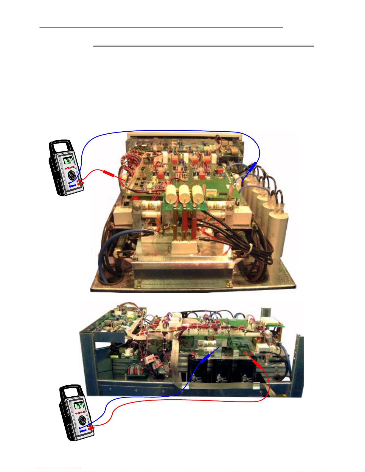
Service Manual
Test Procedures
7 - 14 3x3 UPS
Issue 2 - November 2001
Primary and Secondary DC Bus Voltage Check (refer to Figure 7Ć7)
1. Remove the UPS top cover.
2. With a DVM check the secondary DC bus across F3 and F2 has fallen less than 20V dc.
3. With a DVM check the primary DC bus across F1 and F4 has fallen less than 20V dc.
The UPS is now safe to carry out further investigation.
Note: The half DC bus level can also be monitored if required by connecting the
DVM across the +ve or Ćve fuse and the DC common (neutral) bus bar as
show n in Figure 7Ć7.
Figure 7-7 DC Bus Voltage check
F2
F3
Check Secondary DC
bus between Fuse F3
& F2
765V DC
To Check Half Secondary DC bus Voltage check for 382V DC between Fuse
F3 and Neutral Bus. (a similar check can be carried out from F2)
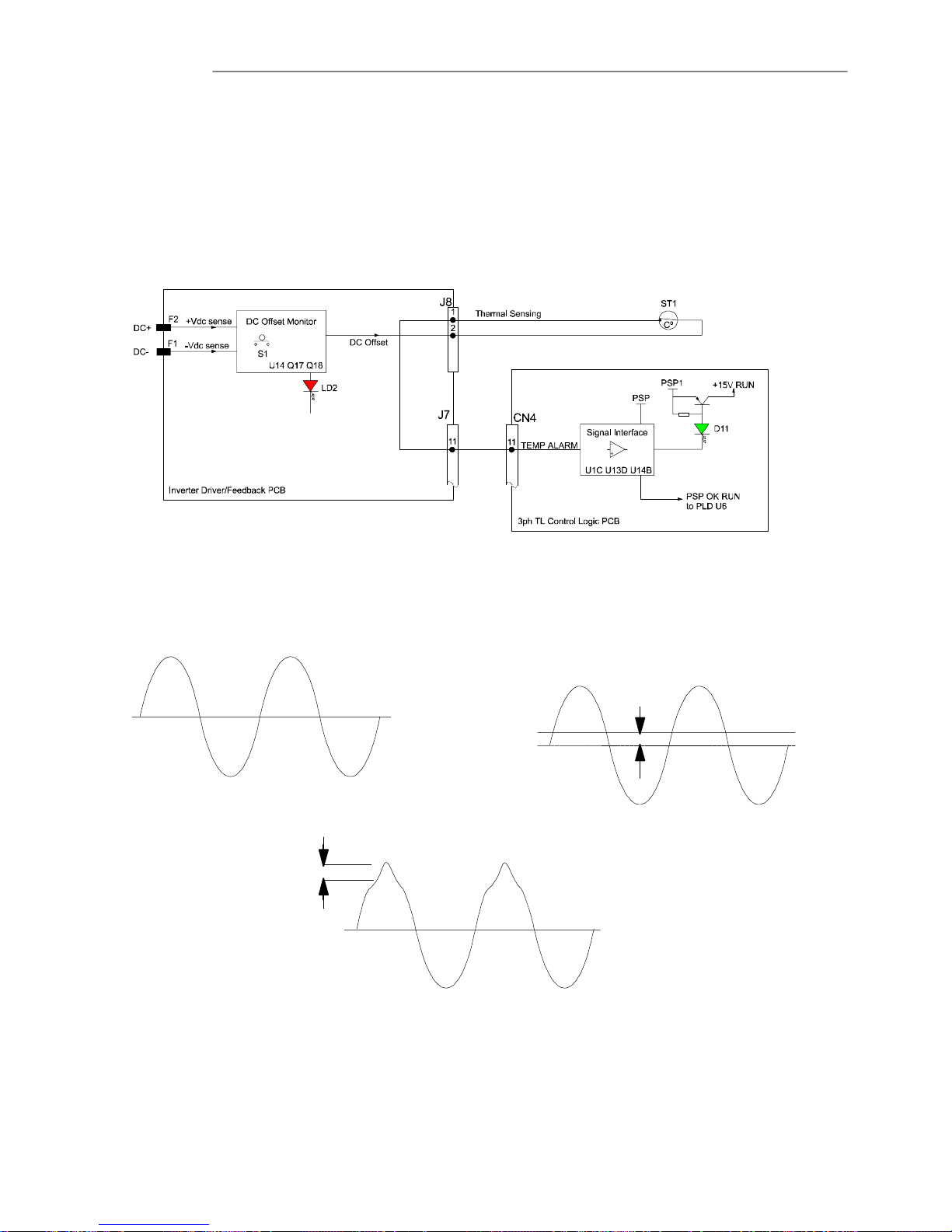
Service Manual
Test Procedures
7 - 153x3 UPS
Issue 2 - November 2001
7.8.2 - DC offset
Fault indication
The output of the UPS is monitored by the Inverter Driver Feedback PCB for any DC component on the
output waveform. If the level of DC exceeds the limit of 400mV, a signal is generated and switched to
the control logic PCB. This signal is switched through the thermostat ST1 as shown below in Figure 7Ć8.
Figure 7-8 DC Offset Alarm Signal
The UPS will transfer to the bypass and the red LED LD 2 on the inverter driver/feedback PCB Part Nº
OSDE0071, will illuminate. The red LED D11 on the 3ph TL control logic PCB Part Nº OSDE0072 will
extinguish. The UPS will remain on bypass until the alarm condition is reset using the Reset push switch
S1 on the PCB, or the UPS is completely powered down and restarted.
Figure 7-9 Typical output current waveforms with DC offset.
0
0
0
Normal output current waveform
Output current waveform showing DC Offset
Effect on the Output current
waveform with unbalanced non linear
load
DC Offset
DC Offset
DC Offset Condition
The most likely cause of a `DC OFFSET' condition could be:
1. The UPS is supplying an unbalanced non linear load, this could be on any phase.
2. The load is drawing DC current.
A common reason for this is an input bridge rectifier on a computer power supply is
defective and only half wave rectifying its input power.
3. An inverter gate drive circuit is defective.
This could cause the inverter EIGHT's switching to be out of balance.

Service Manual
Test Procedures
7 - 163x3 UPS
Issue 2 - November 2001
Action
1. To determine if the DC offset problem is load related.
Replace the normal load temporarily with a resistive load and monitor the alarm condition, if
it disappears then the problem lies with the load.
2. To measure the level of DC offset present, connect the test circuit shown in Figure 7Ć9 to the
output of the UPS.
Figure 7-10 DC offset test circuit.
V3
U3 W3N3
R1
R1
R1
C1
C3
C2
Meter
All R = 120kÙ 2Watt
All C = 1ìF 250V
DC checked across each
capacitor normal level
50mV
3. Measure the DC mV across each phase capacitor the nominal level should be 50mV the
maximum 400mV.
a) Measure the DC offset level with the load connected if it is out of limits then the problem
is load related.
b) Check again with no load if the DC offset level is out of limits then the problem may lie
with the UPS.
4. If the DC Offset appears to be generated by the UPS, check the voltage across D94 and D89
on the inverter driver/feedback PCB Part Nº OSDE0071.
The voltage should be equal.
5. If an unequal voltage is measured then the fault is likely to be in either the inverter gate drive
or IGBT's.
Check that the IGBT drive circuit is correct and the IGBT devices are serviceable.
6. If the circuit and IGBT checks are OK the problem points to a defective monitoring circuit in
the inverter driver/feedback PCB.
Replace the inverter driver/feedback PCB.
7. Reconnect all cables and fit any covers removed.
8. Restore the UPS to its normal running condition.

Service Manual
Test Procedures
7 - 17 3x3 UPS
Issue 2 - November 2001
7.8.3 - IGBT Replacement
General Fitting Information.
When fitting heatsink mounted devices the following factors must be observed.
1. Ensure that when handling devices correct anti static precautions are taken and the handler
is connected to earth using a antistatic wrist band.
2. Take care when handling devices. Do not fit any device that may have been dropped or
damaged.
3. Spread a thin film of heatsink compound Part Nº 04010340 over the whole of the base area.
Ensure there are no gaps and the base and heatsink are free of foreign material before
fitting.
4. Position the device on the heat sink and insert the correct length screws listed in Table 7Ć4
5. Tighten the screws to finger tightness, ensuring that the threaded holes are not damaged.
6. Tighten screws alternately part way before applying the full torque to individual screws, to
prevent unnecessary strain being applied to the device substrate.
7. Use the tightening sequence shown in Figure 7Ć10.
Figure 7-11 Screw tightening sequence.
1
2
3
4
8. Finally tighten the screws to the appropriate torque shown in Table 7Ć4.
Torque Nm
Circuit Ref. Part Nº
Pan head
Sems
Heatsink Terminal
Bridge PD1 0CADTSSKD82/12 M4 X 12FL 2 2
Diode CD1 CD2 0CSDRFBYT261P12 3.5 3.5
Diode CD4 CD5 0CADR210230 2 2
Diode CD3 0CADRFBYT231 2 2
SCR S7 S8 0CASR212132 M5 X 16FL 3 3
SCR S1, 2, 3, 4, 5 & S6 0CASR212391 M5 X 16FL 3 3
IGBT Q1, Q2, Q3 (Inverter) 0CATR210415 M5 X 13FL 3
M4 Ć 2
M5 Ć 3
IGBT Q4 (Converter) 0CATD212420 M5 X 16FL 2.5 2
Table 7-5 Torque settings for Hinet devices.
Inverter IGBT (Q1 Q2 Q3) Removal
1. Power down the UPS and carry out the DC bus discharge routine.
2. Gain access to the UPS power section by removing the top and side covers.
3. Disconnect and remove the Inverter driver/feedback PCB Part NºOSDE0071. Follow the
procedure on page 7Ć32.
4. Disconnect fuse F2 and F3.
5. Remove capacitors C9 and C10
6. Remove the Inverter bus bar retaining screws from the IGBT's and lift off the bus bars.

Service Manual
Test Procedures
7 - 183x3 UPS
Issue 2 - November 2001
7. Disconnect the cables attached to current transformer TA1 TA2 and TA3 IGBT connection
extension pillars and lift off the CT's.
Note: An inĆsitu test for a short circuit IGBT can be carried out at this point
before the devices are removed.
8. Disconnect the gate drive fastĆon connectors from the IGBT's and note their position for
reĆassembly.
9. Remove the four retaining IGBT securing Allen screws from each IGBT and remove each
IGBT.
10. Test each IGBT for serviceability follow the IGBT test procedure on page 7Ć20.
11. Replace any components found defective.
IGBT fitting is the reverse of the removal procedure refer to Table 7-6 for correct IGBT gate drive conĆ
nector location.
Table 7-6 Inverter IGBT Gate Drive Connectors
IGBT Gate Lead Terminal
IGBT Connector
4 5 7 6
Q1 J11 Red Black Black Red
Q2 J9 Blue Black Black Blue
Q3 J11 Red Black Black Red
Converter IGBT (Q4) Removal
1. Power down the UPS and carry out the DC bus discharge routine.
2. Gain access to the UPS power section by removing the top and side covers.
3. Disconnect and remove the Inverter driver/feedback PCB Part NºOSDE0071. Follow the
procedure on page 7Ć32.
4. Remove the converter bus bar retaining screws from IGBT Terminal 2 and 4.
5. Remove capacitors C9 and C10 from the bus bars.
6. Remover the connecting screws from diodes CD4 and CD5
7. Remove the bus bar retaining screws from the insulated pillar.
8. Slacken the converter current transformer (TA4) mounting bolt securing the CT and bus bar,
and reposition to gain access to Q4.
Note: An inĆsitu test for a short circuit IGBT can be carried out at this point
before the devices are removed.
9. Disconnect the gate drive fastĆon connectors from the IGBT and note their position for
reĆassembly.
10. Remove the four retaining IGBT securing Allen screws and remove from IGBT from the
heatsink.
11. Carry out a test of the IGBT for serviceability follow the IGBT test procedure on page 7Ć20.
12. Replace IGBT if found defective.
IGBT fitting is the reverse of the removal procedure refer to Table 7-7 for correct IGBT gate drive conĆ
nector location.
Table 7-7 Converter IGBT Gate Drive Connectors
IGBT Gate Lead Terminal
IGBT
3 5
Q4 Red Black

Service Manual
Test Procedures
7 - 193x3 UPS
Issue 2 - November 2001
7.8.4 - IGBT testing
Two types of IGBT are used on the series UPS.
a) Twin pack devices used in the inverter section.
b) A single pack devices used on the converter.
All the devices currently used on the , are the latest `advanced second' or `third' generation type,
these have a higher gate emitter impedance. Difficulty can be experienced testing this type of IGBT
using a standard DVM, as they lack the battery power to switch on the device.
This difficulty can give rise to an incorrect diagnosis and a perfectly serviceable IGBT may be marked
as defective.
As a normal DVM cannot produce a high enough voltage to switch on a advanced second or third generĆ
ation IGBT, it is recommended that the functional test is carried out with the use of an external dc power
supply.
Note: A 9V PP3 battery can successfully be used as the external voltage source.
Hinet Third Generation IGBT's
Circuit Ref. IGBT Type Liebert Hiross Part Nº
IGBT Q1, Q2, Q3 EUPEC BSM150GB120DN2 Twin 0CATR210415
IGBT Q4 EUPEC BSM200GA120DN2 (6) Single 0CATD212420
Table 7-8 Third generation IGBT usage
Testing the IGBT
1. Power down the UPS and gain access to the power sections by following the procedure on
page 7Ć3.
2. Ensure that the power sections have been completely isolated, check using a DVM.
3. Locate the IGBT to be tested and totally isolate it by disconnecting its gate drive lead from
the inverter drivers and feedback PCB, and the power leads from the screwed terminals.
4. Test the IGBT using a DVM and a 9V dc power source.
Follow the procedure shown in Table 7Ć6. Refer to Figure 7Ć11 for the IGBT internal circuit.
5. Replace the IGBT if required.
Ensure the correct fitting procedure is used. Refer to Table 7Ć4 for correct torque values.
6. Reconnect the IGBT gate drive and power connections.
7. Carry out a test of the Inverter or Converter.
8. Replace all panels removed and restore the UPS to its normal working condition.

Service Manual
Test Procedures
7 - 203x3 UPS
Issue 2 - November 2001
Table 7-9 Functional check of power IGBT's
Action
DVM/Battery Lead
Connection
DVM
Indication
(mV)
Interpretation
+ve to: Ćve to: IGBT
Connect DVM across the emitter cathode
junction.
1
[1]
2 Ć 7
[2 Ć 5]
OL
IGBT switched off a serviceable condition.
Reverse DVM leads to check internal
diode.
2 Ć 7
[2 Ć 5]
1
[1]
0.355
Diode forward resistance.
ReĆconnect DVM leads across emitter cathĆ
ode.
1
[1]
2 Ć 7
[2 Ć 5]
OL
Connect the 9V power supply (battery)
negative Ćve
2 Ć 7
[2 Ć 5]
OL
Touch the +ve Battery lead to gate (base).
6
[3]
2 Ć 7
[2 Ć 5]
0.345
This will switch on the device.
ReĆcheck the emitter cathode junction.
1
[1]
2 Ć 7
[2 Ć 5]
0.345
Low mV reading indicates IGBT has
switched on and is serviceable.
Disconnect the battery +ve and Ćve leads.
ć ć 0.345
Turn off the device by shorting B2(G2) and
E2.
1
[1]
2 Ć 7
[2 Ć 5]
OL
High resistance indicates the IGBT is off.
Note: Terminal connections for single pack IGBT are shown in [square brackets]
Testing the second IGBT
Connect DVM across the emitter cathode
junction.
3 1 OL
IGBT switched off a serviceable condition.
Reverse DVM leads to check internal
diode.
1 3 0.336
Diode forward resistance.
ReĆconnect DVM leads across emitter cathĆ
ode.
3 1 OL
Connect the 9V power supply (battery)
negative Ćve
1 OL
Touch the +ve Battery lead to gate (base).
4 1 0.345
This will switch on the device.
Disconnect the battery +ve and Ćve leads.
ć ć 0.345
ReĆcheck the emitter cathode junction.
3 1 0.345
Low mV reading indicates IGBT has
switched on and is serviceable.
Turn off the device by shorting B1 and E1.
3 1 OL
High resistance indicates the IGBT is off
Note: The DVM readings shown in the above table are typical they will vary
slightly from device to device and with the type of meter used.

Service Manual
Test Procedures
7 - 213x3 UPS
Issue 2 - November 2001
Figure 7-12 IGBT internal circuit and external connections.
Twin pack IGBT (Part Nº OCATR210415)
Single pack IGBT (Part Nº OCATD212420)

Service Manual
Test Procedures
7 - 223x3 UPS
Issue 2 - November 2001
7.8.5 - SCR Testing
The UPS use two types of SCR devices, one to switch the reserve bypass and inverter output
to the load. The second type to connect the battery to the primary DC bus in the event of failure of the
utility supply.
The two different types of device used to perform these functions are both of twin pack construction howĆ
ever S7 and S8 have a single SCR and Diode. arrangement.
Table 7-10 SCR
Circuit Ref. SCR Type Part Nº
SCR S1 S2 S3 S4 S5
S6
SEMIKRON SKKT 92/12E 91A Twin Pack 0CASR212420
SCR S7 S8 SEMIKRON SKKH132/12E
132A combined SCR &
Diode Pack
0CASR212132
Failure of a static switch or battery SCR will initiate the appropriate indication on the LED display and
will normally fail open circuit O/C or short circuit S/C. If a faulty device is suspected it can be checked
using a DVM. A short circuit across the anode cathode junction will be quickly apparent, however an
open circuit cannot so easily be diagnosed as the high resistance indicated is the normal state of the
device when turned off.
The Gate Cathode resistance can also be measured and should be in the range of 10 to 20 ohms for
a serviceable SCR, a high resistance would indicate an open circuit.
It is therefore recommended that a functional test of the SCR is carried out using the simple test circuits
shown in Figure 7Ć12 and Figure 7Ć14.
Twin Pack SCR Replacement (S1 S2 S3 S4 S5 S6)
1. Power down the UPS and carry out the DC bus discharge routine.
2. Gain access to the UPS power section by removing the top and side covers.
3. Disconnect and remove the Inverter driver/feedback PCB Part NºOSDE0071. Follow the
procedure on page 7Ć32.
4. Remove the two SCR gate drive leads from terminals 4 and 6 from each SCR and note their
position.
Note: Note SCR S6 has the gate drive leads reversed blue to 4 red to 6.
5. Remove the terminal standoffs and screws to release the bus bars from SCR terminals 1. 2
and 3.
6. Disconnect the second gate drive leads from SCR terminals 1 and 2.
Table 7-11 SCR Gate Drive Lead Connection
Gate Drive Terminal
SCR
4 6 1 2
S1 Blue Red Black Brown
S2 Red Blue Brown Black
S3 Blue Red Black Brown
S4 Red Blue Brown Black
S5 Blue Red Black Brown
S6 Blue Red Black Brown
7. Remove the two SCR Allen retaining screws from each SCR and lift from the Heatsink
8. Carry out the following functional test on each SCR and replace if required.
SCR fitting is the reverse of the removal procedure refer to 12. for correct SCR gate drive connector locaĆ
tion.

Service Manual
Test Procedures
7 - 233x3 UPS
Issue 2 - November 2001
Figure 7-13 Testing the twin pack SCR
9 volt power source
and switch
9 volt power source
and switch
+ve
ćve
9 volt power
source
Test lamp
Test lamp
9 volt power
source
+ve
ćve
+ve ćve
+većve
Twin pack SCR
To functionally test a twin pack SCR as shown in Figure 7Ć12 a DC power source and test lamp is reĆ
quired, typically a 9V PP3 battery and 12V bulb.
1. Connect the bulb and battery to SCR1 as shown, connect the +ve to the anode (1) and ćve
to the cathode (2) terminal.
2. Using a second power source or link from the battery connect the +ve lead to SCR1 gate
terminal 4 and the ćve lead gate terminal 5.
3. Switch on the SCR by briefly making the gate circuit, use a switch if available.
The SCR will fire and the bulb will light and remain on. The bulb provides a current source
for the SCR and it will continue to fire.
4. Remove the +ve connection from terminal 1.
The bulb will extinguish an the SCR will switch off.
5. Repeat the test for SCR2.
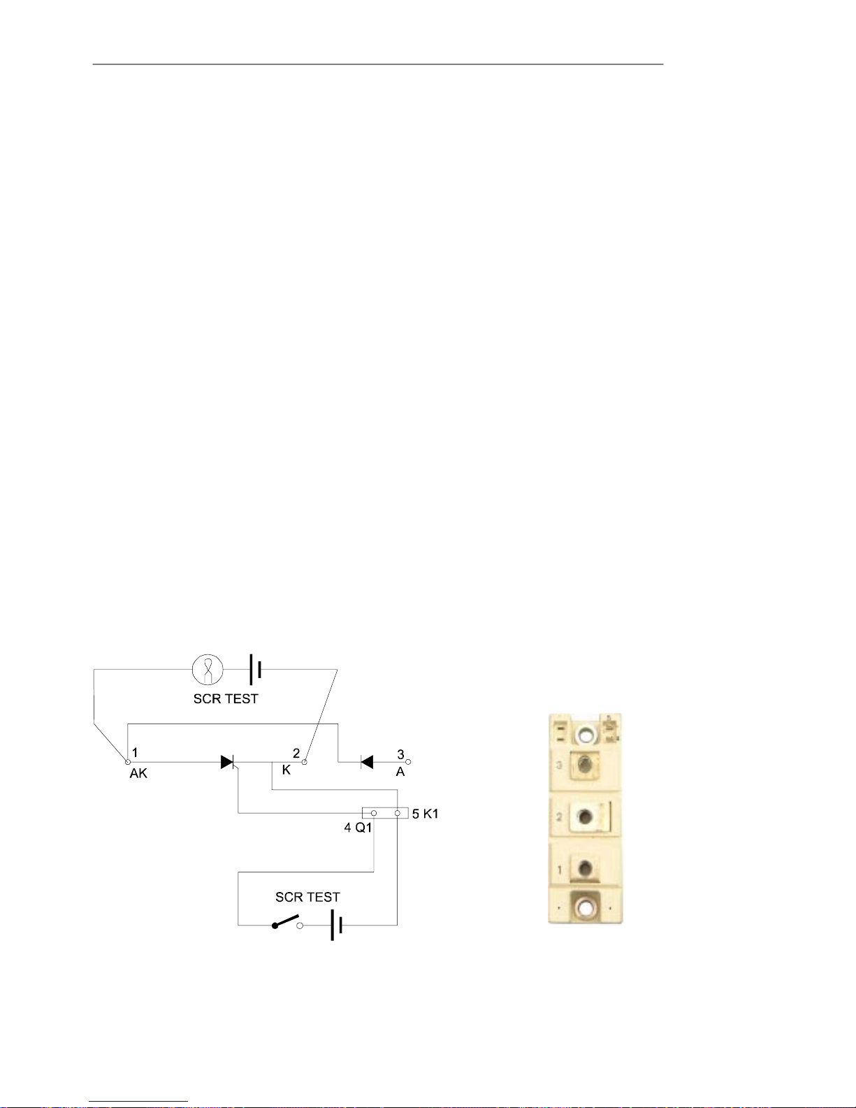
Service Manual
Test Procedures
7 - 243x3 UPS
Issue 2 - November 2001
Single SCR and Diode Pack Replacement. (S7 S8)
1. Power down the UPS and carry out the DC bus discharge routine.
2. Gain access to the UPS power section by removing the top and side covers.
3. To gain access to the SCR's disconnect and remove the Input Filter PCB Part NºOSDE0079.
Follow the procedure on page 7Ć38.
SCR S7
4. Disconnect the Red and Black gate drive Connectors from 4Q1 (red) and 5K1 (black).
5. Disconnect the Battery negative bus bar from SCR terminal 2.
6. Disconnect Fuse F4 bus bar from SCR terminal 1.
7. Disconnect black leads from R2 to SCR terminal 1 and 2.
8. Remove red leads from SCR terminal 1 and 2 which connect to the fast on connectors F12
(SCR 1) and F11 (SCR 2) on the Inverter driver/feedback PCB.
Note: There is no connection to SCR terminal 3.
9. Remove the two SCR Allen retaining screws from the SCR and lift from the Heatsink.
Note: There is a deĆcoupling capacitor linking the heatsink from SCR mounting
screw to the neutral bus bar.
SCR S8
10. Disconnect the battery +ve cable from SCR terminal 3.
11. Disconnect red leads from R1 to SCR terminal 1 and 2.
12. Remove fuse F1 bus bar from SCR terminal 2.
13. Remove the input bridge bus bar from SCR terminal 1.
14. Remove red leads from SCR terminal 1 and 2 which connect to the fast on connectors F13
(SCR 1) and F14 (SCR 2) on the Inverter driver/feedback PCB.
15. Carry out the following functional test on each SCR and replace if required.
SCR fitting is the reverse of the removal procedure.
Figure 7-14 Single SCR Test.
9 volt power source
and switch
+ve
ćve
Test lamp
9 volt power
source
+ve ćve
Single SCR & Diode pack
 Loading...