

Powertronix Mizar, Alcor User Manual
POWERTRONIX
UNINTERRUPTIBLE POWER SUPPLY
User Manual
MIZAR 10÷15 kVA
ALCOR 20÷40 kVA
Document : DT0430 English - Ptx
Revision Date Issued by Approved by
03 09/02/2010 Riccardo G. Andrea G.
04 04-03-2010 Riccardo G. Andrea G.
05
Powertronix spa reserves the right to modify this document without notice
R&D – USER MANUAL DT0430-E04
Page 1 of 46

1. GENERAL OVERVIEW............................................................................................................................................4
1.1. UPS GENERAL DESCRIPTION.......................................................................................................................4
1.1.1. UPS APPLICATIONS ...............................................................................................................................4
1.1.2. POWER AND AUTONOMY.....................................................................................................................4
1.1.3. SAFETY AND SIMPLICITY OF USE ......................................................................................................4
1.2 CONFIGURATION AND OPTIONAL EQUIPMENT.........................................................................................5
1.2.1. BASE CONFIGURATION.........................................................................................................................5
1.2.2. BATTERY CABINET.................................................................................................................................5
1.2.3. TRANSFORMER CABINET.....................................................................................................................5
1.2.4. REMOTE COMMUNICATION CARD .....................................................................................................6
1.2.5. UPS MANAGEMENT SOFTWARE.........................................................................................................6
1.2.6. REMOTE PANEL ......................................................................................................................................7
1.2.7. REMOTE E.P.O. PUSH - BUTTON.........................................................................................................7
1.2.8. REMOTE MANUAL BY-PASS.................................................................................................................7
1.3 OPERATINGPRINCIPLE..................................................................................................................................8
1.3.1. UPS BLOCK DIAGRAM...........................................................................................................................8
1.3.2. INPUT STAGE, POWER MODULE AND OUTPUT STAGE ................................................................8
1.3.3. LOGIC AND AUXILIARY CIRCUITS.......................................................................................................9
1.3.4. BATTERIES...............................................................................................................................................9
1.3.5. MANUAL BY-PASS...................................................................................................................................9
1.3.6. FRONT PANEL .........................................................................................................................................9
2. INSTALLATION INSTRUCTIONS........................................................................................................................10
2.1 GENERAL INFORMATION..............................................................................................................................10
2.2 RECEPTION AND IDENTIFICATION.............................................................................................................10
2.3 STORAGE.........................................................................................................................................................10
2.4 UPS POSITIONING..........................................................................................................................................11
2.5 ROOM SPECIFICATIONS...............................................................................................................................13
2.6 LAYOUT AND CONNECTIONTO THE MAINS.............................................................................................14
2.7 UPS AUXILIARY CONNECTIONS..................................................................................................................20
2.7.1. REMOTE COMMUNICATION BOARD.................................................................................................21
2.7.2. REMOTE PANEL (Optional) ..................................................................................................................22
2.7.3. UPS MANAGEMENT SOFTWARE.......................................................................................................23
2.7.4. REMOTE E.P.O. BUTTON.....................................................................................................................23
2.7.5. REMOTE MANUAL BY-PASS...............................................................................................................24
2.7.6. EARTH CONNECTION ..........................................................................................................................24
3 CONTROL PANEL.................................................................................................................................................25
3.1. INTRODUCTION..............................................................................................................................................25
3.2. LCD CONTROLPANEL...................................................................................................................................26
3.2.1. MENU 1: UPS STATUS AND ALARMS................................................................................................28
3.2.2. UPS IN FAULT CONDITIONS...............................................................................................................29
3.2.3. MENU 2: MEASUREMENTS.................................................................................................................30
3.2.4. MENU 3: UPS COMMANDS..................................................................................................................31
3.2.5. MENU 4: PANEL SETUP .......................................................................................................................31
3.2.6. MENU 5: EVENTS RECORDER MANAGEMENT...............................................................................31
3.2.7. MENU 6: SERVICE MODE ....................................................................................................................32
Powertronix spa reserves the right to modify this document without notice
R&D – USER MANUAL DT0430-E04
Page 2 of 46

4. INSTRUCTIONS FOR USING THE UPS.............................................................................................................33
4.1. INTRODUCTION..................................................................................................................................................34
4.2. POWERSWITCHES........................................................................................................................................34
4.3. UPS START-UP CONFIGURATION...............................................................................................................36
4.4. INSTRUCTION FOR SYSTEM START-UP IN “AUTOMATIC” MODE........................................................37
4.5. INSTRUCTION FOR SYSTEM START-UP IN “NORMAL” MODE..............................................................38
4.6. INSTRUCTIONSFOR COMPLETE SHUTDOWN OF THE UPS .................................................................39
4.7. INSTRUCTIONSFOR SWITCHINGSYSTEM TO MANUALBY-PASS MODE..........................................40
4.8. INSTRUCTIONSFOR RETURN FROM MANUAL BY-PASS MODE TO NORMAL OPERATION...........41
4.9. E.P.O.(EMERGENCYPOWER OFF) STOP.................................................................................................41
4.10. MANAGING THE UPS BATTERY..............................................................................................................42
4.11. BATTERYTEST PROGRAMMING............................................................................................................42
5 UPS IN PARALLEL................................................................................................................................................43
5.1 SYSTEM SET-UP.............................................................................................................................................43
6 TROUBLESHOOTING...........................................................................................................................................44
6.1. GENERAL ALARMS.........................................................................................................................................44
6.2. FIRE..................................................................................................................................................................45
6.3. FAULTS RELATED TO THE NATURE OF THE LOAD .................................................................................45
7. SCHEDULED MAINTENANCE.............................................................................................................................46
7.1. ANNUALMAINTENANCE(OR PERFORMED EVERY SIX MONTHS IN THE CASE OF UNITS IN
CRITICAL APPLICATIONS).......................................................................................................................................46
Powertronix spa reserves the right to modify this document without notice
R&D – USER MANUAL DT0430-E04
Page 3 of 46

1. GENERAL OVERVIEW
1.1. UPS GENERAL DESCRIPTION
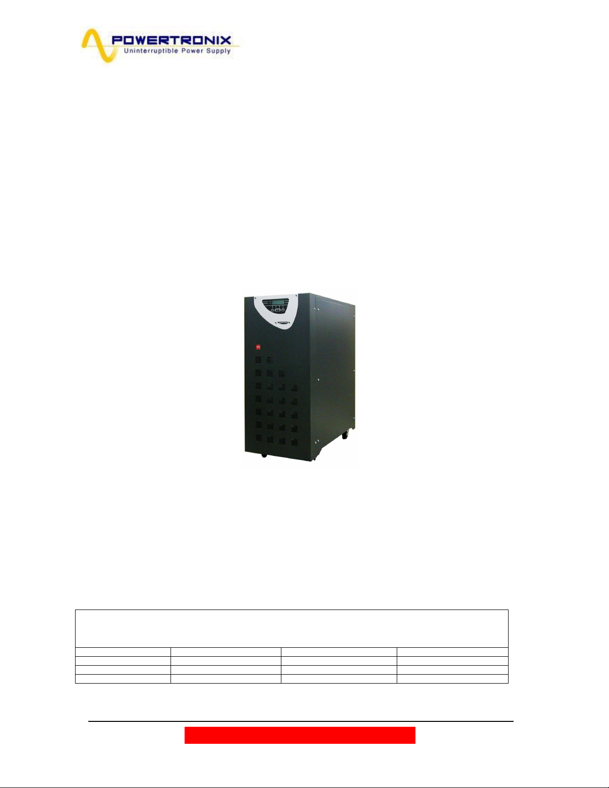
These UPS families have the compact construction, with the outer metal frame and the electronic circuits and
power components inside. All user accessible elements are placed on the back side, while the control panel –
on the front side.
The top and side covers can be removed, giving an access to the internal part of the UPS for the service or
maintenance purposes.
The front side of all units contains the user interface panel useful for monitoring, maintenance and control.
The terminal block for the electrical connection to the mains, reserve, load, external batteries, and the main
switch, are located on the back side of the unit.
The internal batteries are placed in the lower part of the UPS, with an access from front side.
1.1.1. UPS APPLICATIONS
The new UPS family was designed to provide stabilized and filtered power, especially for supplying
sophisticated and sensitive electronic devices (i.e. for data processing systems). Alcor and Mizar UPSes
can be used to supply electronic systems of medical centers, police stations, motorway tunnels,
broadcasting stations, banks, technical and administrative offices, requiring the power source free from
voltage and frequency variations.
1.1.2. POWER AND AUTONOMY
Thanks to its modular design, the UPSes are available in two series with rated power from 10kVA to 15kVA
(Mizar) and from 20kVA to 40kVA (Alcor).
These two families have different power sections, while batteries and cabinet remain the same.
Both UPSes can utilize the internal battery block of 60 pcs. of 5, 7.2 or 9Ah batteries.
An external battery modules can be used to increase the UPS autonomy.
1.1.3. SAFETY AND SIMPLICITY OF USE
All the UPS elements available for user daily maintenance are insulated and disconnected from hazardous
voltages.
Control of the overload and excessive temperatures guarantees the immediate and most suitable
intervention in the case when one of these conditions occurs during operation.
The operator can view the UPS status on the front panel and perform shut down or switching operations
easily (see chap. 3 page 19).
The unit is provided with the E.P.O. (Emergency Power Off). This function is activated by pressing the
button located on the front panel.
A remote E.P.O (optional) switch can be connected to UPS to provide remote emergency power off action.
The UPS state can be easily monitored with the personal computer and an interacting program (optional) or
through the remote panel (optional), especially when the UPS is installed in unmonitored areas. See chap.
1.2.5 - 1.2.6.
Powertronix spa reserves the right to modify this document without notice
R&D – USER MANUAL DT0430-E04
Page 4 of 46

1.2 CONFIGURATION AND OPTIONAL EQUIPMENT
1.2.1. BASE CONFIGURATION
The UPS is available in the following configurations:
Input Output Power Mizar / Alcor
Three-phase Input Three-phase Output 10÷15 kVA / 20÷40 kVA
Three-phase Input Single-phase Output 10÷15 kVA / 20÷40 kVA
Single-phase Input Single-phase Output 10÷15 kVA / 20÷40 kVA
1.2.2. BATTERY CABINET
When the autonomy time provided with the basic configuration is not sufficient, additional optional battery
cabinet can be connected to the UPS.
The batteries cabinet can contain up to 2 battery blocks of 4.5 – 5 – 7.2 – 9 Ah.
1.2.3. TRANSFORMER CABINET
If a galvanic isolating transformer is required, it can be positioned inside UPS cabinet in the place of the
internal batteries - in this case an external battery cabinet is essential.
The standard transformer is three-phase/three-phase (or single-phase/single-phase or three-phase/singlephase) with 1:1 ratio, but it can be supplied with a different transformation ratio upon customer request.
Powertronix spa reserves the right to modify this document without notice
R&D – USER MANUAL DT0430-E04
Page 5 of 46
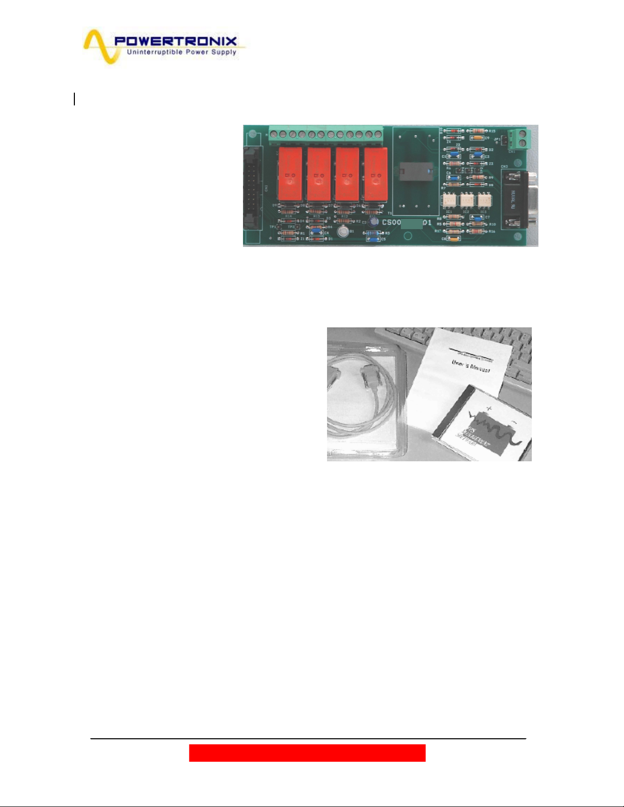
1.2.4. REMOTE COMMUNICATION CARD
M1
Remote communication board
(the code CS0098), gives
possibility of monitoring and
communicating with UPS.
Monitoring can be implemented
with the PC and dedicated
software or through a remote
panel. There are also voltage free
contacts available on the terminal
board M1
(more info at pages 21-22)
1.2.5. UPS MANAGEMENT SOFTWARE
The “UPS MANAGEMENT” Generex communication
software allows interaction between UPS and PC or
the network based on Windows, Win-NT, Novell, OS2,
Dec, and Linux operating systems.
The software is used to monitor and control
parameters of one or more UPSes supplying the
network (more info at page 23)
CN1
CN3
Powertronix spa reserves the right to modify this document without notice
R&D – USER MANUAL DT0430-E04
Page 6 of 46
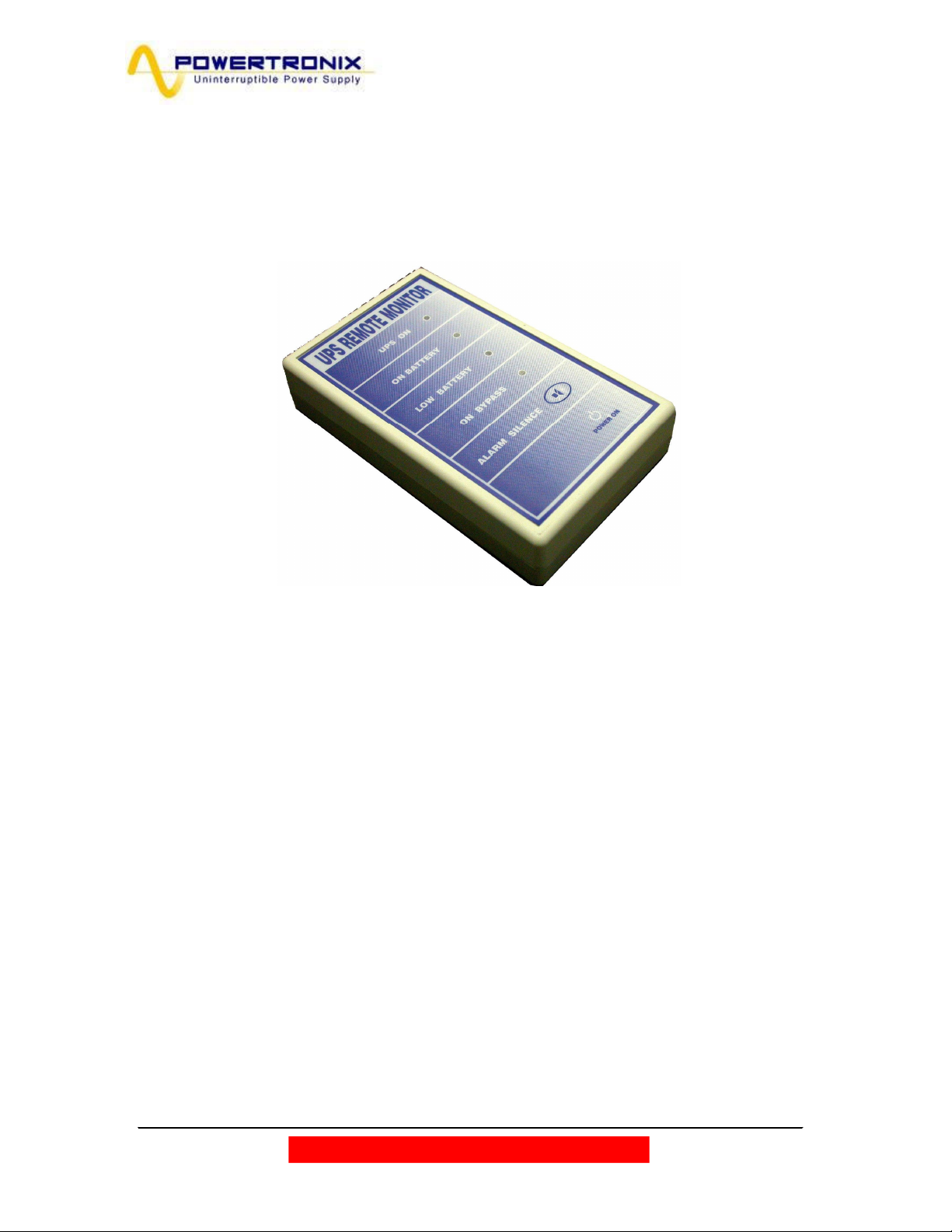
1.2.6. REMOTE PANEL
The remote panel is used for remote viewing of the UPS state, it shows the status of the main UPS blocks
with LED indicators and the sound signalization in the case of alarm conditions (more info at page 22)
1.2.7. REMOTE E.P.O. PUSH - BUTTON
The remote E.P.O push-button provides the safe, remote way to fast and full disable the unit running in the
event of an emergency (more info at page 23)
1.2.8. REMOTE MANUAL BY-PASS
The remote Manual By-Pass is a security system that allows, when closed, to connect directly load to the
power line, excluding the UPS (more info at page 24).
Powertronix spa reserves the right to modify this document without notice
R&D – USER MANUAL DT0430-E04
Page 7 of 46
1.3 OPERATING PRINCIPLE
I1
I5
I2
=
INGRESSO
USCITA UPS
PASS MANUALE
MODULO
The UPS described here is an on-line dual conversion type UPS with automatic by-pass in compliance with
European standard EN62040-1-2. This UPS performs a dual conversion of the incoming voltage
continuously and without interruption.
The absence of direct connection between mains and the load provides blocking all voltage and frequency
disturbances. The dual conversion guarantees that the output energy is always well regulated and has
correct voltage and frequency values, ideal for the operation of professional applications.
When the input voltage exceeds the allowed range or - more frequently - is not present, the load is supplied
by converted energy from the batteries.
The system is supplied with an automatic by-pass. In the event of a UPS fault or overload, the by-pass
connects immediately the load directly to the mains through a reserve line, making possible normal load
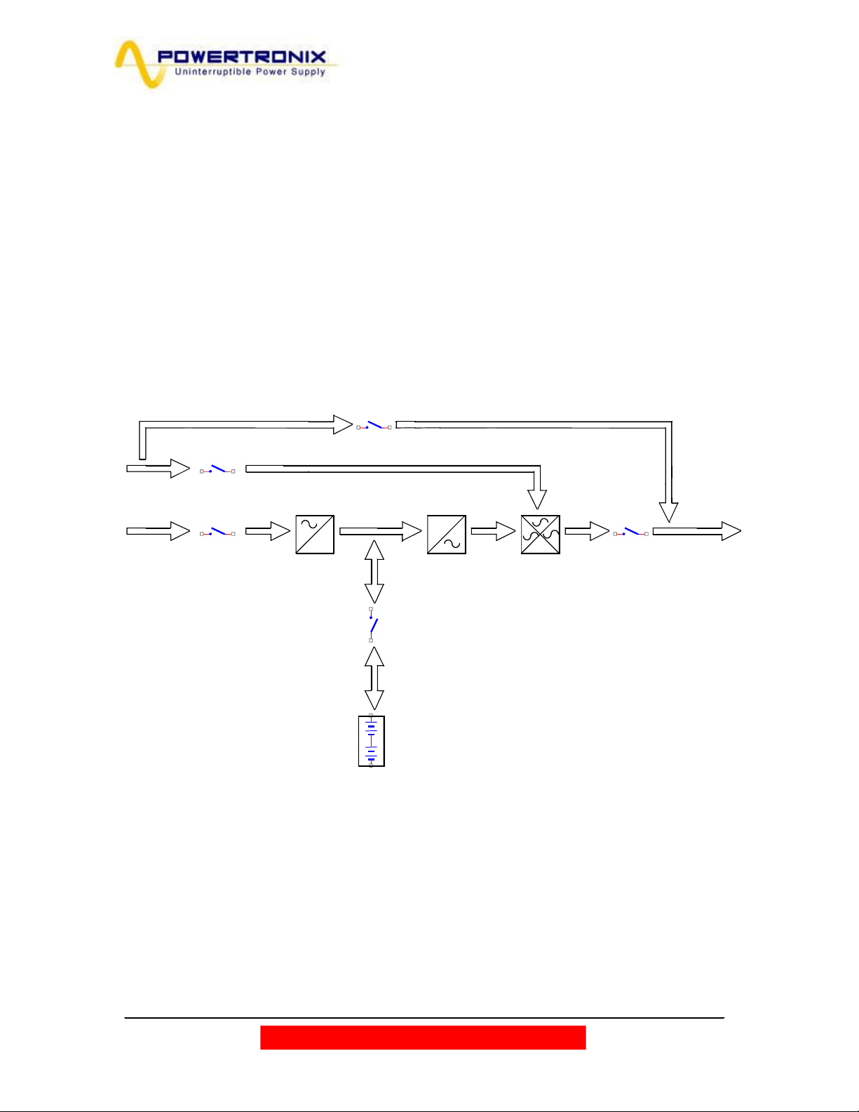
operation without interruption. See fig. 1.3.1
1.3.1. UPS BLOCK DIAGRAM
INGRESSO
RISERVA
BY-
I3
RETE DI RISERVA
=
RETE
PRINCIPALE
PFC
BATTERIA
MODULO
INVERTER
1.3.2. INPUT STAGE, POWER MODULE AND OUTPUT STAGE
BY-PASS MANUALE
I4
S.SWITCH
From the input bars the mains are connected via the MAINS INPUT l1 switch to the power module.
The rectifier regulates the DC voltage to a reference value, charging continuously the battery.
Then the DC voltage supplies the inverter, which feeds the load with regulated sinusoidal voltage (phase
and amplitude controlled).
In normal operating conditions, the static switch (providing energy to the load) selects the inverter as the
voltage source; in the case of fault or overload, the UPS output is redirected to the reserve line. This
operation allows providing the energy to the load. When the cause of the alarm disappears, the static
switch automatically selects the inverter to feed the load again.
Powertronix spa reserves the right to modify this document without notice
R&D – USER MANUAL DT0430-E04
Page 8 of 46

1.3.3. LOGIC AND AUXILIARY CIRCUITS
The control logic occupies the separate board (0SDE0150) and represents the “intelligence” of the UPS.
It manages operations of the step-up converter, inverter and by-pass, based on feedback signals taken
from the power module. The control logic also manages the other three boards, i.e. the battery charger,
auxiliary power supply and signal interface.
The battery charger handles recharging of the outside batteries connected to the UPS.
The signal interface receives the signals from the control logic and converts them into the protocol required
by the front panel of the UPS and also the relays board. Going backwards, the selected commands from
the front panel (automatic by-pass forcing) and/or relay board (EPO) are sent from the signal interface to
the control logic which interprets them and performs desired operation – like switch on/off inverter or shuts
off the UPS.
The auxiliary power supply supplies all the boards and electronic components in the UPS.
1.3.4. BATTERIES
The battery set provides energy to the system when the input mains is out of the allowed range or not
present; in all other cases batteries are constantly recharged by the charger module. In this way the
batteries are always ready for use when required.
1.3.5. MANUAL BY-PASS
The manual by-pass is useful in the situations, when it is necessary to disable the UPS and keep the load
supplied by the mains (i.e.: UPS stopped, fault, etc.). can be activated with using the MANUAL BY-PASS
(l3) switch, located in the rear part of the UPS (refer to chapter 4). In normal operating conditions this circuit
breaker remains in rest position, protected with the mechanical lock (the padlock).
1.3.6. FRONT PANEL
The UPS can be managed via the front panel. Using the panel it is possible to execute the commands,
display states and measurements and reset the alarm circuits.
The panel is equipped with an LCD screen used to display the operating status of the UPS, the load and all
types of measurement (see chap. 3)
Powertronix spa reserves the right to modify this document without notice
R&D – USER MANUAL DT0430-E04
Page 9 of 46
2. INSTALLATION INSTRUCTIONS
2.1 GENERAL INFORMATION
This chapter describes the system installation procedures and lists the following subjects:
• Reception and identification
• Storage
• UPS positioning
• Room specifications
• Arrangement and connection to mains
• UPS Auxiliary connections
• Earth connection
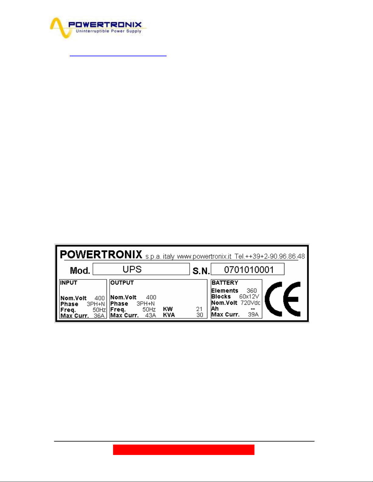
2.2 RECEPTION AND IDENTIFICATION
After removing the packing, visually inspect (inside and outside) the UPS and battery module (if included)
to check for any damage that could occur during shipping. If there is any damage, inform the shipper or
retailer immediately.
Check the supplied material against the packing slip.
The machine has an adhesive identification plate indicating the type, power and serial number; it is located
on the rear side of the unit (Fig.2.2)
Fig. 2 . 2
2.3 STORAGE
If the system is not going to be installed immediately it must be stored in an environment with adequate
protection against excessive humidity and sources of extreme heat (from +5 to +40°C, humidity less than
95% without condensation).
If the battery module is supplied, also make sure that no more than 6 months pass between one
battery recharge and the next. Once this period of time has elapsed, temporarily hook the UPS up to the
mains and run it for the time needed to recharge the batteries.
Powertronix spa reserves the right to modify this document without notice
R&D – USER MANUAL DT0430-E04
Page 10 of 46
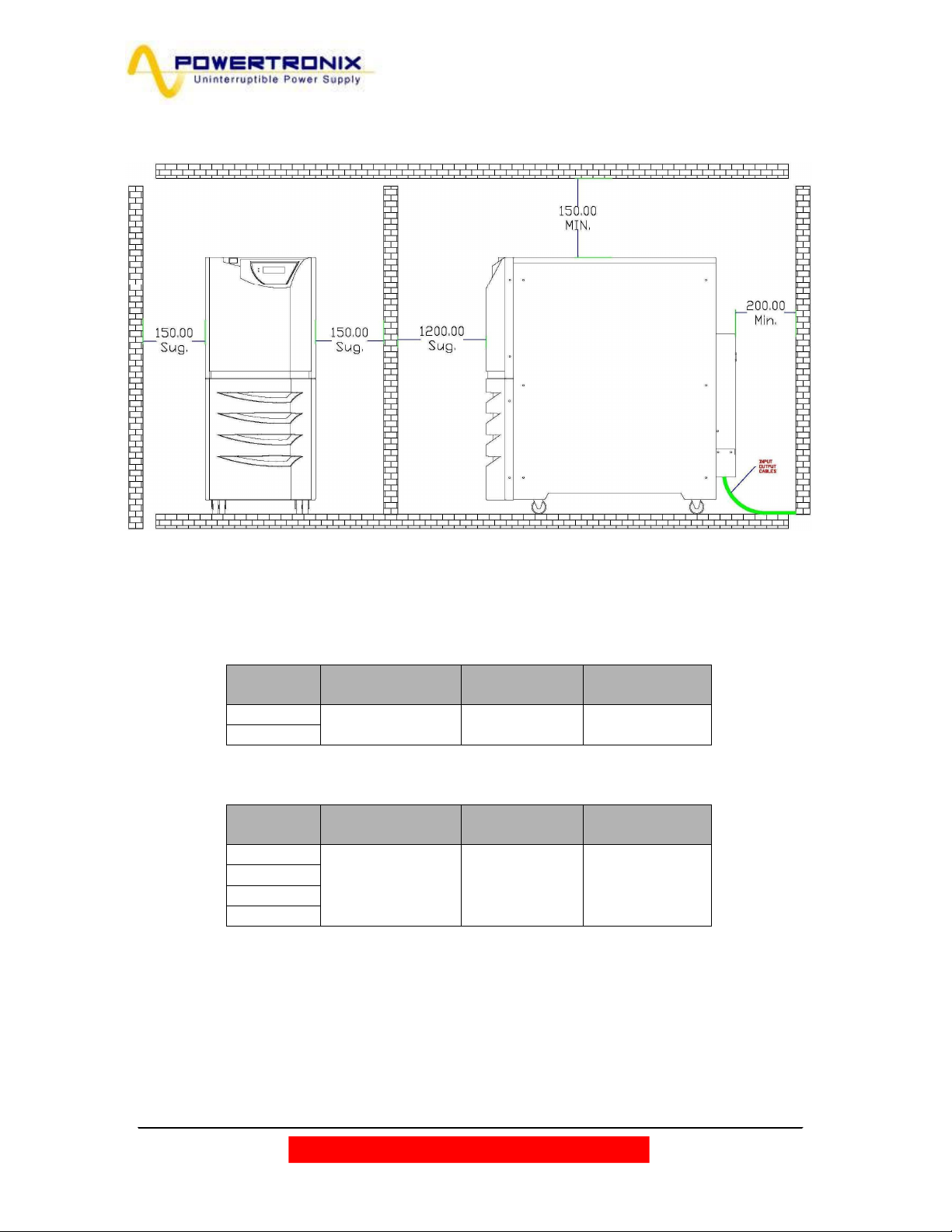
2.4 UPS POSITIONING
All dimensions are in millimeters.
The same cabinet is used for both series (MIZAR and ALCOR). The mechanical parameters are described
in the following tables:
MIZAR
POWER
(kVA)
10
15
DIMENSIONS
WxDxH (mm)
WEIGHT (Kg)
w/o batteries
WEIGHT (Kg)
with batteries
390x900x900 70 220
Tab. 2.4a
ALCOR
POWER
(kVA)
DIMENSIONS
WxDxH (mm)
WEIGHT (Kg)
w/o batteries
WEIGHT (Kg)
with batteries
20
25
30
390x900x900 80 230
40
Tab. 2.4b
The weight difference is in the case the batteries are mounted or not in the same UPS cabinet.
For handling you need to remember that the machine, unless special arrangements are made, is shipped
and thus handled with the batteries inside, thus you need to refer to the higher weight of the version used.
All the connections are located in the rear panel and can be reached just removing the cover as shown
in Fig. 2.4
Powertronix spa reserves the right to modify this document without notice
R&D – USER MANUAL DT0430-E04
Page 11 of 46

Fig. 2.4 shows the cover and the external connections.
1
2
3
Metal
cover
Fig. 2.4
1. Air cooling grid
2. Communication cards slot (Relay & SNMP)
3. Switches
4. Metal cover
Looking at the back, the cables input is located in the lower side, that it is accessible removing the metal cover
(Fig.2.4)
For the cables connection according to the UPS configuration refer to fig.2.6c/d/e at pages 17-18.
Powertronix spa reserves the right to modify this document without notice
R&D – USER MANUAL DT0430-E04
Page 12 of 46
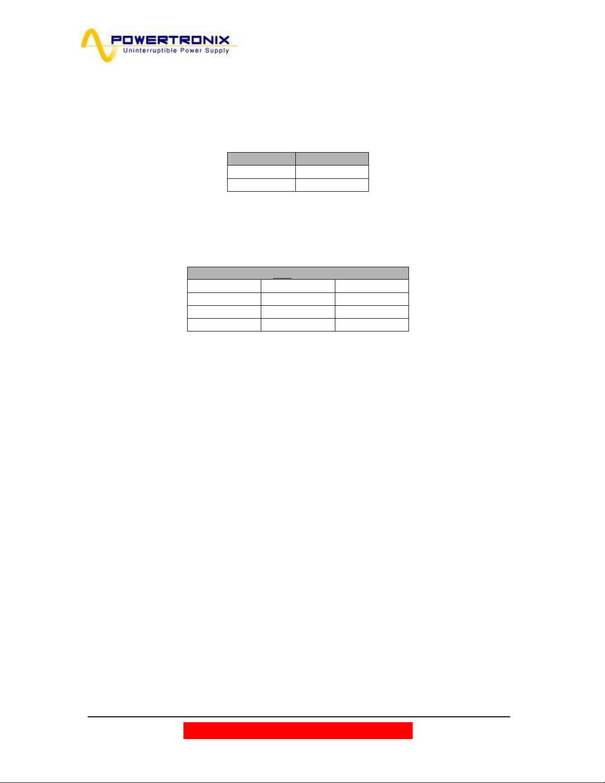
2.5 ROOM SPECIFICATIONS
The room where the UPS is installed must be clean; it must have pollution class 2 (CEI) and must be able
to dissipate the heat produced by the machine, as shown in table 2.5a.
Table 2.5a
Rated P (kVA) Diss. P (W)
15 750
40
For correct battery ventilation, the room must be able to ensure an exchange of air equal or greater than
what is shown in table 2.5b.
Table 2.5b
Air exchange only for battery hydrogen
4.5 Ah batteries 7Ah batteries 9 Ah batteries
(60 blocks) (60 blocks) (60 blocks)
-- -- --
-- -- --
Remember that the average life of the batteries is closely correlated with the operating temperature;
a temperature of around 20°C is normally recommended.
(when the temperature rises above 20°, for each 10° higher the battery life drops by 50%)
Powertronix spa reserves the right to modify this document without notice
R&D – USER MANUAL DT0430-E04
Page 13 of 46

2.6 LAYOUT AND CONNECTION TO THE MAINS
For connection to the mains a layout solution like the one shown in diagram 2.6 is recommended. The
circuit breakers B-C-D are magnetothermic type without differential protection, or if this is required, with a
triggering current greater than 0.3A, delayed and suitable for load with DC current (type A).
Switch A is used as external BY-PASS.
Block diagram 2.6
PANNELLO DI
DISTRIBUZIONE
D
A
I3 BY-PASS
B
I2 INPUT RISERVA
RESERVE LINE
I4 USCITA
UPS
Config.: 3 in – 3 out
RETE DI RIS ERVA
PANNELLO DI
DISTRIBUZIONE
C
CARICO
RETE P RINCIPA LE
D
A
B
I1 INPUT MAINS
I3 BY-PASS
I2 INPUT RISERVA
=
=
I5 BATTERIA
BATTERIE INTERNE
UPS
RESERVE LINE
I4 USCITA
Config.: 1 in – 1 out
C
CARICO
RETE DI RISER VA
RETE P RINCIPA LE
I1 INPUT MAINS
=
=
I5 BATTERIA
BATTERIE INTERNE
PANNELLO DI
DISTRIBUZIONE
RETE DI RIS ERVA
D
A
I3 BY-PASS
B
C
CARICO
RETE P RINCIPA LE
I2 INPUT RISERVA
I1 INPUT MAINS
=
RESERVE LINE
I4 USCITA
=
I5 BATTERIA
BATTERIE INTERNE
UPS
Config.: 3 in – 1 out
Powertronix spa reserves the right to modify this document without notice
R&D – USER MANUAL DT0430-E04
Page 14 of 46
 Loading...