

Powertronix Quasar, 10kVA, 15kVA, 20kVA, 30kVA Service Manual


Manual Registration
Prelim Page i3x3 UPS Preliminary Pages
Issue 2 - November 2001
Manual Registration
S THIS MANUAL IS A CONTROLLED DOCUMENT AND WILL BE PERIODICALLY UPĆ
DATED.
S IN ORDER TO ENSURE THAT YOU RECEIVE ANY AMMENDMENT PLEASE REGĆ
ISTER THIS MANUAL WITH THE TECHNICAL SUPPORT DEPARTMENT BY REĆ
TURNING A COPY OF THIS FORM TO:
Manual Registration
Number
Name of Registered Holder
Address of
Holder
Company
Name/Building
Street/Road
Area/region
Town/City
County/State
Post/Zip Code
Country
Telephone Number
FAX Number
E Mail Address

Amendment Record
Amendment Record
Service Manual
Manual Serial
Number:
Please enter the Manual Serial Nº
for future record
Issue
Nº
Issue
Date
Amendment Amended By Date
1
Initial issue
ć ć

Service Manual
Amendment Record
Prelim Page iii 3x3 UPS Preliminary Pages
This Service manual contains information concerning the installation operation and service of the folĆ
lowing UPS
EQUIPMENT PART NUMBER
With battery Without battery
10 kVA UPS
15 kVA UPS
20 kVA UPS
30 kVA UPS

UTILITY
SUPPLY
WARNING
PLEASE
NOTE
Service Manual
Limitations of Use
Prelim Page iv 3x3 UPS Preliminary Pages
Issue 2 - November 2001
Limitations of Use
ELECTROMAGNETIC COMPATABILITY
The equipment covered by this manual complies with the requirements of the EMC DirecĆ
tive 89/336/EEC and the published technical standards. Continued compliance requires
installation in accordance with these instructions and use of manufacturer approved accesĆ
sories only.
WARNINGThe UPS is a Class A product.
When used in a domestic environment a unit may cause radio interference,
If this is the case the user may be required to take additional measures
WARNING HIGH EARTH LEAKAGE CURRENT.
Earth connection is essential before connecting the utility supply.
This equipment must be earthed in accordance with local electrical codes.
WARNING This UPS does not incorporate automatic backĆfeed protection. A warning label must be
fitted to all external primary power isolators stating:
ISOLATE THE UNINTERRUPTIBLE POWER SYSTEM BEFORE WORKING ON THIS CIRCUIT.
The UPS should not be supplied from electrical power systems of the `IT'
(Impédance à Terre) type.
(IEC 364 Ć ELECTRICAL INSTALLATION OF BUILDINGS)
Note: Where use on `IT' systems is required an optional input isolation transformer should
be fitted.
CAUTION This equipment is fitted with RFI suppression filters
Earth leakage exceeds 3.5mA but is less than 300mA.
Transient and steadyĆstate earth leakage currents, which occur when starting the equipĆ
ment, should be taken into account when selecting instantaneous RCCB or RCCD devices.
Note also that the earth leakage currents of the load will be carried by this RCCB or RCCD.
These products are intended for Commercial/Industrial use only, and are not suitable for
use in any life support applications.

Service Manual
Important Instructions for safe use
Prelim Page v 3x3 UPS Preliminary Pages
Important Instructions for safe use
GENERALThe UPS must be approved engineer before it is put into serĆ
vice. Failure to observe this condition will invalidate any implied warranty.
In common with other types of high power equipment, dangerous voltages are present with
the UPS and battery enclosure. The risk of contact with these voltages is minimised as the
live component parts are housed behind a hinged lockable door.
Further internal safety screens make the equipment protected to IP20 standards.
No risk exists to any personnel when operating the equipment in the normal manner, followĆ
ing the recommended operating procedures.
All equipment maintenance and servicing procedures involving internal access, should be
carried out by trained personnel.
The UPS is for indoor use only. It must be protected from rain or excessive moisture and
installed in a clean environment, free from flammable liquids, gasses, or corrosive subĆ
stances. Do not put drinks, plants, or any other containers holding liquids, on top of the unit.
BATTERIES Battery manufacturers supply details of the necessary precautions to be observed when
working on, or in the vicinity of, a large bank of battery cells. These precautions should be
followed at all times.
Particular attention should be paid to the recommendations concerning local environĆ
mental conditions and the provision of protective clothing, first aid and fireĆfighting facilities.
TEST EQUIPMENT
When the battery is under charge it is earthĆreferenced about its midĆpoint e.g. if the battery
is being charged at 460V the battery extremities will be =230V and Ć230V with respect to
neutral (earth). When using mains powered test equipment such as oscilloscopes in the
UPS high voltage area, always use a differential mode of operation to avoid the need to disĆ
connect the oscilloscope frame earth.
PERSONNEL
When working inside the UPS (trained personnel only) is recommended that protection be
worn to prevent eye damage, should an electric arc be struck by mishandling or severe
electrical fault.
Some of the power components are very heavy. If their removal is necessary ensure that
sufficient manpower is available, otherwise use adequate mechanical handling equipment.
When working in the general area of the UPS where high voltages are present, a second
person should be standingĆby to assist and summon help in case of accident.

Service Manual
Personnel Categorisation
Prelim Page vi3x3 UPS Preliminary Pages
Issue 2 - November 2001
Personnel Categorisation
The following definitions are given to categorise the scope, and use of this service
manual:
Operator/User
This service manual is outside the scope for use by personnel who have received instrucĆ
tion on the correct operation of the UPS controls; limited to operation of the unit circuit
breakers and the Front Control Panel; operator/users are not permitted to remove any panĆ
els which are retained by screws.
Competent Personnel
The Troubleshooting section, and Service procedures contained in this manual are norĆ
mally outside the scope of personnel categorised competent; though they may be aware
of the dangers appropriate to working with hazardous voltages. A Competent engineer is
deemed to have sufficient technical skills/training to make electrical connections, install
batteries, close and open circuit breakers/fuses etc. (i.e. a qualified electrician) he is not
categorised as service personnel.
Service Personnel
This
etraining and are password authorised.
Service manual is designed for use by engineers who have received the relevant
Important Symbols
The warning triangle shown above indicate personal safety instructions.
Follow these instructions carefully to avoid injury.

Service Manual
Specification
Prelim Page vii UPS Preliminary Pages
Issue 2 - November 2001
Specification
10kVA 15kVA 20kVA 30kVA
Input Data
Nominal Input Voltage 400V 3 phase, neutral and earth
Input Voltage Range 300 ć 480Vac (330 ć 480Vac full charging capability)
Nominal Input Frequency 50/60Hz
Input Frequency Range 40 ć 70Hz
Maximum Input Current at Nominal Input Voltage 18.5A 25.3A 31.7A 45.0A
Input Current Harmonic Distortion (THD) <30% (without filter)
Input Power Factor 0.95 (over specified load and voltage ranges)
Output Data
Nominal Output Voltage 380, 400 or 415Vac selectable
Output Voltage Adjustment Range 360 ć 415Vac
Output Voltage Stability
Static Balanced Load
Static 50% Unbalanced Load
Static 100% Unbalanced Load
Dynamic 50% Load Step
Dynamic 100% Load Step
±1%
±3%
±5%
±3%
±5%
Output Voltage Transient Recovery Time <30ms (to 3% RMS)
Output Voltage Distortion (THD)
Linear Load
Non Linear Load (100% 3:1 Crest Factor Load)
<3%
<5%
Output Voltage Phase Displacement
Balanced Load
100% Unbalanced Load
120° ±1%
120° ±3%
Nominal Output Frequency 50 or 60Hz
Output Frequency Regulation
Synchronised With Input
Free Running
±1% or ±4%, selectable
±0.005%
Maximum Slew Rate 1Hz/sec
Nominal Output Power Rating
kVA
kW
10
8
15
12
20
16
30
24
Output Nominal Power Factor 0.8
Overload Capability on Inverter (Load Will Transfer to
Static Bypass if Times are Exceeded)
125% for 10 minutes, 150% for 10 seconds
Output Short Circuit Current 300% of nominal current for 100ms
Maximum Load Crest Factor 3:1 (at full load without deĆrating)

Service Manual
Specification
Prelim Page viiiUPS Preliminary Pages
Issue 2 - November 2001
10kVA 15kVA 20kVA 30kVA
Intermediate DC Circuit Data
Internal Battery Type valve regulated, sealed, lead acid cells
Number of Battery Cells 192
Nominal Battery Voltage 384Vdc
Internal Battery Rating 7.2Ahr 2 x 7.2Ahr 2 x 7.2Ahr 3 x 7.2Ahr
Full Load Autonomy Time With Standard Internal Battery
(For part load and battery configuration Autonomy times
refer to the table on page Ćxiii)
6 minutes 9 minutes 6 minutes 6 minutes
DC Bus Overvoltage Trip 500Vdc
End of Battery Discharge Voltage 320Vdc
Battery PreĆalarm Discharge Voltage Level 350Vdc
Battery Charger Nominal Float Voltage at 20°C 432Vdc
Battery Charger Voltage Stability ±1%
Battery Charger Output Voltage Ripple <1%
Maximum Battery Recharging Current 1, 3, 5 or 7A (Selectable)
Automatic Battery Test 12, 24 or 48 hour impedance test
System Data
Topology
True OnĆline double conversion, high frequency,
transformerless design
Power Upgrade Yes ć up to a maximum rating of 30kVA
StartĆup On Battery Yes
System Efficiency (Excluding Battery Charging)
50% Linear Load
100% Linear Load
88%
90%
88%
90%
89%
91%
90%
91%
Full Load Inverter Efficiency 94% 94% 94% 94%
Operating Temperature Range 0° Ć 40°C (20°C for optimal battery lifetime)
Storage Temperature Range Ć20° to 70°C (excluding battery)
Operating Relative Humidity Range <95% (nonĆcondensing)
Maximum Altitude Above Sea Level 1000m before deĆrating
Audible Noise Level At 1 Metre <52dBA
Relay Communications Card
Alarm Contacts
DB9 connector
On Battery
Low Battery
Internal Terminals
On Battery
Low Battery
On Bypass
UPS On
Remote Stop Contacts Open to disable inverter and static bypass
Cable Entry Bottom entry at rear of unit

Service Manual
Specification
Prelim Page ixUPS Preliminary Pages
Issue 2 - November 2001
10kVA 15kVA 20kVA 30kVA
Bypass Data
Input Voltage Range For Bypass Switching Nominal ±10%
Overload Capability on Static Bypass 150% for 30 minutes, 1000% for 100 m seconds
Mechanical Data
Unit Dimensions (w x h x d) 530 x 1220 x 950 mm
Unit Weight Without Battery 185kg
Unit Weight With Standard Battery 275kg 365kg 365kg 455kg
Shipping Dimensions (w x h x d) 545 x 1260 x 965 mm
Unit Shipping Weight Without Battery 215kg
Unit Shipping Weight With Standard Battery 305kg 395Kg 395kg 485kg
Enclosure Rating IP20
Colour
RAL 7035 Metal Covers
RAL 7042 Plastic Door
Design Standards
Safety
Radio Frequency Interference (RFI)
Electromagnetic Compatibility (EMC)
European Directive
Quality
EN50091Ć1Ć1
EN50091Ć2 Class A
CE marked compliance LVD / EMC
ISO9001

Service Manual
Specification
Prelim Page xUPS Preliminary Pages
Issue 2 - November 2001
BATTERY AUTONOMY TIMES
Configuration Part Nº
Approximate Autonomy Time in Minutes at
Stated Load and 25°C
Configuration
Part N
100% 75% 50% 25% 10%
3 Phase 10kVA
UPS with 1 internal set of batteries
(Standard configuration)
6 9 17 35 115
UPS with 2 internal sets of batteries
+ 1 x BATT
17 24 40 82 282
UPS with 3 internal sets of batteries
+ 2 x BATT
28 41 66 133 486
UPS with 4 internal sets of batteries
+ 3 BATT
41 57 94 191 600
3 Phase 15kVA
UPS with 2 internal sets of batteries
(Standard configuration)
9 14 24 55 157
UPS with 3 internal sets of batteries
+ 1 x BATT
17 24 40 91 269
UPS with 4 internal sets of batteries
+ 2 x BATT
24 35 56 128 398
3 Phase 20kVA
UPS with 2 internal sets of batteries
(Standard configuration)
6 9 17 39 108
UPS with 3 internal sets of batteries
+ 1 x BATT
11 17 28 64 178
UPS with 4 internal sets of batteries
+ 2 xBATT
17 24 40 91 263
3 Phase 30kVA
UPS with 3 internal sets of batteries
(Standard configuration)
6 9 17 40 110
UPS with 4 internal sets of batteries
+ 1 x BATT
9 14 24 56 157

Service Manual
Table of Contents
Prelim Page i3x3 UPS Preliminary Pages
Issue 1 - May 2001
Table of Contents
Manual Registration i. . . . . . . . . . . . . . . . . . . . . . . . . . . . . . . . . . . . . . . . . . . . . . . . . . . . . . . . . . .
Amendment Record ii. . . . . . . . . . . . . . . . . . . . . . . . . . . . . . . . . . . . . . . . . . . . . . . . . . . . . . . . . . .
Limitations of Use iv. . . . . . . . . . . . . . . . . . . . . . . . . . . . . . . . . . . . . . . . . . . . . . . . . . . . . . . . . . . . .
Important Instructions for safe use v. . . . . . . . . . . . . . . . . . . . . . . . . . . . . . . . . . . . . . . . . . . . . .
Personnel Categorisation vi. . . . . . . . . . . . . . . . . . . . . . . . . . . . . . . . . . . . . . . . . . . . . . . . . . . . . .
Specification vii. . . . . . . . . . . . . . . . . . . . . . . . . . . . . . . . . . . . . . . . . . . . . . . . . . . . . . . . . . . . . . . . .
Table of Contents xi. . . . . . . . . . . . . . . . . . . . . . . . . . . . . . . . . . . . . . . . . . . . . . . . . . . . . . . . . . . . .
Chapter 1 - Overview 1 - 1. . . . . . . . . . . . . . . . . . . . . . . . . . . . . . . . . . . . . . . . . . . . . . . .
1.1 - Introduction 1 - 1. . . . . . . . . . . . . . . . . . . . . . . . . . . . . . . . . . . . . . . . . . . . . . . . . . . . . . . . . . . .
1.2 - Equipment Construction 1 - 1. . . . . . . . . . . . . . . . . . . . . . . . . . . . . . . . . . . . . . . . . . . . . . . . .
1.2.1 - Principle of operation 1 - 2. . . . . . . . . . . . . . . . . . . . . . . . . . . . . . . . . . . . . . . .
1.2.2 - UPS Power Configuration 1 - 3. . . . . . . . . . . . . . . . . . . . . . . . . . . . . . . . . . . . .
1.2.3 - Battery fuses switch 1 - 3. . . . . . . . . . . . . . . . . . . . . . . . . . . . . . . . . . . . . . . . .
Chapter 2 - Installation 2 - 1. . . . . . . . . . . . . . . . . . . . . . . . . . . . . . . . . . . . . . . . . . . . . .
2.1 - Installation (Mechanical) 2 - 1. . . . . . . . . . . . . . . . . . . . . . . . . . . . . . . . . . . . . . . . . . . . . . . . .
2.1.1 - Preliminary Checks 2 - 1. . . . . . . . . . . . . . . . . . . . . . . . . . . . . . . . . . . . . . . . . .
2.2 - Installation (Electrical) 2 - 3. . . . . . . . . . . . . . . . . . . . . . . . . . . . . . . . . . . . . . . . . . . . . . . . . . .
2.2.1 - Power Cabling 2 - 3. . . . . . . . . . . . . . . . . . . . . . . . . . . . . . . . . . . . . . . . . . . . . .
2.2.2 - Power Cable connections 2 - 3. . . . . . . . . . . . . . . . . . . . . . . . . . . . . . . . . . . . .
2.2.3 - Safety Earth 2 - 5. . . . . . . . . . . . . . . . . . . . . . . . . . . . . . . . . . . . . . . . . . . . . . . .
2.2.4 - Protective devices 2 - 5. . . . . . . . . . . . . . . . . . . . . . . . . . . . . . . . . . . . . . . . . . .
2.3 - Battery Installation 2 - 6. . . . . . . . . . . . . . . . . . . . . . . . . . . . . . . . . . . . . . . . . . . . . . . . . . . . . .
2.3.1 - Battery Safety 2 - 6. . . . . . . . . . . . . . . . . . . . . . . . . . . . . . . . . . . . . . . . . . . . . . .
2.3.2 - Battery Installation Check 2 - 6. . . . . . . . . . . . . . . . . . . . . . . . . . . . . . . . . . . . .
2.3.3 -Installing the Battery Upgrade Kit (BATTCABLE)2 - 9. . . . . . . . . . . . . .
2.4 -Setting Standard Relay Interface PCB2 - 12. . . . . . . . . . . . . . . . . . . . . . . . . . . . . . . . . . . . .
2.4.1 - Setting Options on the standard Relay Interface 2 - 12. . . . . . . . . . . . . . . . .
2.4.2 - Relay Interface Connections 2 - 13. . . . . . . . . . . . . . . . . . . . . . . . . . . . . . . . . .
2.4.3 - Remote EPO (Emergency Power Off) 2 - 14. . . . . . . . . . . . . . . . . . . . . . . . . .
2.4.4 - Emergency Power Off (E.P.O.) pushĆbutton connection 2 - 14. . . . . . . . . . .
2.4.5 - Connection to Personal Computer 2 - 14. . . . . . . . . . . . . . . . . . . . . . . . . . . . .
2.4.6 - UPS Monitoring 2 - 15. . . . . . . . . . . . . . . . . . . . . . . . . . . . . . . . . . . . . . . . . . . . .
Chapter 3 - Commissioning 3 - 1. . . . . . . . . . . . . . . . . . . . . . . . . . . . . . . . . . . . . . . . . .
3.1 - PreĆpower Checks 3 - 1. . . . . . . . . . . . . . . . . . . . . . . . . . . . . . . . . . . . . . . . . . . . . . . . . . . . . .
3.2 - Validating the Installation 3 - 1. . . . . . . . . . . . . . . . . . . . . . . . . . . . . . . . . . . . . . . . . . . . . . . .
3.2.1 - Positioning 3 - 1. . . . . . . . . . . . . . . . . . . . . . . . . . . . . . . . . . . . . . . . . . . . . . . . . .
3.2.2 - Preliminary checks 3 - 1. . . . . . . . . . . . . . . . . . . . . . . . . . . . . . . . . . . . . . . . . . .
3.3 - Setting UPS Parameters 3 - 2. . . . . . . . . . . . . . . . . . . . . . . . . . . . . . . . . . . . . . . . . . . . . . . . .
3.3.1 - Control Logic PCB CS0072. 3 - 2. . . . . . . . . . . . . . . . . . . . . . . . . . . . . . . . . . .
3.3.2 - Driver Interface PCB CS0071 Settings 3 - 2. . . . . . . . . . . . . . . . . . . . . . . . . .
3.3.3 - Auxiliary DC-DC PSU Converter PCB CS0070 Settings 3 - 3. . . . . . . . . .
3.3.4 - Battery Charger PCB CS0074 Setting 3 - 3. . . . . . . . . . . . . . . . . . . . . . . . . .
3.3.5 - LCD Display Monitor Board CS0077 Settings 3 - 3. . . . . . . . . . . . . . . . . . .

Service Manual
Table of Contents
Prelim Page iiUPS Preliminary Pages
Issue 1 - May 2001
3.4 - Initial UPS Start-up. 3 - 4. . . . . . . . . . . . . . . . . . . . . . . . . . . . . . . . . . . . . . . . . . . . . . . . . . . .
3.4.1 - Converter and Inverter Output Calibration. 3 - 4. . . . . . . . . . . . . . . . . . . . . .
3.4.2 - Inverter to Bypass Synchronisation Check. 3 - 6. . . . . . . . . . . . . . . . . . . . .
3.4.3 - Battery Charger Output Calibration. 3 - 6. . . . . . . . . . . . . . . . . . . . . . . . . . . .
3.5 - Power Checks 3 - 7. . . . . . . . . . . . . . . . . . . . . . . . . . . . . . . . . . . . . . . . . . . . . . . . . . . . . . . . . .
3.5.1 - Bupass Failure Test 3 - 7. . . . . . . . . . . . . . . . . . . . . . . . . . . . . . . . . . . . . . . . . .
3.5.2 - Mains Failure Checks 3 - 7. . . . . . . . . . . . . . . . . . . . . . . . . . . . . . . . . . . . . . . .
3.5.3 - Test Transfer to the Reserve Line (Automatic Bypass). 3 - 8. . . . . . . . . . . .
3.5.4 - Manual Bypass Operation Check 3 - 9. . . . . . . . . . . . . . . . . . . . . . . . . . . . . .
3.5.5 - Local EPO 3 - 10. . . . . . . . . . . . . . . . . . . . . . . . . . . . . . . . . . . . . . . . . . . . . . . . . .
3.5.6 - External EPO 3 - 10. . . . . . . . . . . . . . . . . . . . . . . . . . . . . . . . . . . . . . . . . . . . . . . .
3.6 - Normal UPS Start-Up Instructions 3 - 11. . . . . . . . . . . . . . . . . . . . . . . . . . . . . . . . . . . . . . . .
3.6.1 - LCD Messages and LED status after starting the UPS. 3 - 12. . . . . . . . . . .
3.7 - Normal Shutdown to Manual Bypass 3 - 12. . . . . . . . . . . . . . . . . . . . . . . . . . . . . . . . . . . . . .
3.8 - Setting Options 3 - 14. . . . . . . . . . . . . . . . . . . . . . . . . . . . . . . . . . . . . . . . . . . . . . . . . . . . . . . . .
3.8.1 - Setting options on the Relay card 3 - 14. . . . . . . . . . . . . . . . . . . . . . . . . . . . . .
Chapter 4 - Operation and control4 - 1. . . . . . . . . . . . . . . . . . . . . . . . . . . . . . . . . . . .
4.1 - Operator Control Panel 4 - 1. . . . . . . . . . . . . . . . . . . . . . . . . . . . . . . . . . . . . . . . . . . . . . . . . .
Chapter 5 - Functional description 5 - 1. . . . . . . . . . . . . . . . . . . . . . . . . . . . . . . . . . . .
5.1 - Control Logic PCB CS0072 5 - 1. . . . . . . . . . . . . . . . . . . . . . . . . . . . . . . . . . . . . . . . . . . . . .
5.1.1 - Potentiometer adjustment 5 - 1. . . . . . . . . . . . . . . . . . . . . . . . . . . . . . . . . . . .
5.1.2 - Link and Jumper functions 5 - 1. . . . . . . . . . . . . . . . . . . . . . . . . . . . . . . . . . . .
5.2 - Auxiliary Supply PCB CS0070 5 - 2. . . . . . . . . . . . . . . . . . . . . . . . . . . . . . . . . . . . . . . . . . . .
5.2.1 - Battery Threshold settings 5 - 2. . . . . . . . . . . . . . . . . . . . . . . . . . . . . . . . . . . .
5.3 - Driver Interface PCB CS007I 5 - 3. . . . . . . . . . . . . . . . . . . . . . . . . . . . . . . . . . . . . . . . . . . . .
5.3.1 - Bypass Voltage Threshold Adjustment 5 - 3. . . . . . . . . . . . . . . . . . . . . . . . .
5.3.2 - Link and Jumper functions 5 - 3. . . . . . . . . . . . . . . . . . . . . . . . . . . . . . . . . . . .
5.4 - Battery Charger CS0074 5 - 4. . . . . . . . . . . . . . . . . . . . . . . . . . . . . . . . . . . . . . . . . . . . . . . . .
5.4.1 - Battery Charger Voltage Adjustment 5 - 4. . . . . . . . . . . . . . . . . . . . . . . . . . .
5.4.2 - Link and Jumper Functions 5 - 4. . . . . . . . . . . . . . . . . . . . . . . . . . . . . . . . . . .
5.4.3 - Battery test 5 - 5. . . . . . . . . . . . . . . . . . . . . . . . . . . . . . . . . . . . . . . . . . . . . . . . .
5.5 - UPS monitor board PCB CS0077 5 - 5. . . . . . . . . . . . . . . . . . . . . . . . . . . . . . . . . . . . . . . . .
5.6 - Relay Interface PCB CS0082 5 - 6. . . . . . . . . . . . . . . . . . . . . . . . . . . . . . . . . . . . . . . . . . . . .
5.6.1 - EPO Connections. 5 - 6. . . . . . . . . . . . . . . . . . . . . . . . . . . . . . . . . . . . . . . . . . .
5.6.2 - Optional Second Relay Interface PCB 5 - 6. . . . . . . . . . . . . . . . . . . . . . . . . .
5.7 - LCD MIMIC DISPLAY CS0075 5 - 8. . . . . . . . . . . . . . . . . . . . . . . . . . . . . . . . . . . . . . . . . . . .
5.7.1 - Control panel indicator LEDs 5 - 8. . . . . . . . . . . . . . . . . . . . . . . . . . . . . . . . . .
Chapter 6 - Maintenance 6 - 1. . . . . . . . . . . . . . . . . . . . . . . . . . . . . . . . . . . . . . . . . . . . .
6.1 - Scheduled Maintenance 6 - 1. . . . . . . . . . . . . . . . . . . . . . . . . . . . . . . . . . . . . . . . . . . . . . . . .
6.1.1 - Daily Checks 6 - 1. . . . . . . . . . . . . . . . . . . . . . . . . . . . . . . . . . . . . . . . . . . . . . . .
6.1.2 - Weekly Checks 6 - 1. . . . . . . . . . . . . . . . . . . . . . . . . . . . . . . . . . . . . . . . . . . . . .
6.1.3 - Annual Maintenance 6 - 2. . . . . . . . . . . . . . . . . . . . . . . . . . . . . . . . . . . . . . . . .
6.2 - Battery Maintenance 6 - 6. . . . . . . . . . . . . . . . . . . . . . . . . . . . . . . . . . . . . . . . . . . . . . . . . . . .
6.2.1 - Factors Effecting Battery Use 6 - 6. . . . . . . . . . . . . . . . . . . . . . . . . . . . . . . . .
6.2.2 - Battery Testing 6 - 7. . . . . . . . . . . . . . . . . . . . . . . . . . . . . . . . . . . . . . . . . . . . . .

Service Manual
Table of Contents
Prelim Page iii3x3 UPS Preliminary Pages
Issue 1 - May 2001
6.2.3 - Battery capacity testing. 6 - 8. . . . . . . . . . . . . . . . . . . . . . . . . . . . . . . . . . . . . .
6.3 - Battery Replacement 6 - 9. . . . . . . . . . . . . . . . . . . . . . . . . . . . . . . . . . . . . . . . . . . . . . . . . . . .
6.4 - UPS Storage 6 - 9. . . . . . . . . . . . . . . . . . . . . . . . . . . . . . . . . . . . . . . . . . . . . . . . . . . . . . . . . . .
Chapter 7 - Troubleshooting 7 - 1. . . . . . . . . . . . . . . . . . . . . . . . . . . . . . . . . . . . . . . . .
7.1 - Introduction 7 - 1. . . . . . . . . . . . . . . . . . . . . . . . . . . . . . . . . . . . . . . . . . . . . . . . . . . . . . . . . . . .
7.1.1 - General Fault Identification Procedure 7 - 1. . . . . . . . . . . . . . . . . . . . . . . . . .
7.2 - Special Tools. 7 - 2. . . . . . . . . . . . . . . . . . . . . . . . . . . . . . . . . . . . . . . . . . . . . . . . . . . . . . . . . .
7.3 - Removing the UPS Covers 7 - 3. . . . . . . . . . . . . . . . . . . . . . . . . . . . . . . . . . . . . . . . . . . . . . .
7.4 - Component Location 7 - 5. . . . . . . . . . . . . . . . . . . . . . . . . . . . . . . . . . . . . . . . . . . . . . . . . . . .
7.5 - Fault Identification 7 - 9. . . . . . . . . . . . . . . . . . . . . . . . . . . . . . . . . . . . . . . . . . . . . . . . . . . . . .
7.6 -Typical Voltage Values7
7.7 -Fuse Check List7 - 12
- 11. . . . . . . . . . . . . . . . . . . . . . . . . . . . . . . . . . . . . . . . . . . . . . . . . . .
. . . . . . . . . . . . . . . . . . . . . . . . . . . . . . . . . . . . . . . . . . . . . . . . . . .
7.8 -Test Procedures7 - 13. . . . . . . . . . . . . . . . . . . . . . . . . . . . . . . . . . . . . . . . . . . . . . . . . . . . . . . .
7.8.1 - DC Bus Discharge Routine, Shutdown to Maintenance Bypass. 7 - 13. . .
7.8.2 -DC offset7 - 15. . . . . . . . . . . . . . . . . . . . . . . . . . . . . . . . . . . . . . . . . . . . . . . . . . .
7.8.3 - IGBT Replacement 7 - 17. . . . . . . . . . . . . . . . . . . . . . . . . . . . . . . . . . . . . . . . . .
7.8.4 -IGBT testing7 - 19. . . . . . . . . . . . . . . . . . . . . . . . . . . . . . . . . . . . . . . . . . . . . . . .
7.8.5 - SCR Testing 7 - 22. . . . . . . . . . . . . . . . . . . . . . . . . . . . . . . . . . . . . . . . . . . . . . . .
7.8.6 - Inverter Drive Signal Testing 7 - 26. . . . . . . . . . . . . . . . . . . . . . . . . . . . . . . . . .
7.8.7 -Checking power circuit capacitors.7 - 27. . . . . . . . . . . . . . . . . . . .
7.9 -PCB Replacement Procedures7 - 28. . . . . . . . . . . . . . . . . . . . . . . . . . . . . . . . . . . . . . . . . . .
7.9.1 - Auxiliary DC Ć DC Converter Part Nº OSDE0070 (PCB Label: CS0070 Exx) 7 - 28
7.9.2 - LCD UPS Monitor Board OSDE0077 (PCB Label: CS0077 Exx) 7 - 29. . . .
7.9.3 - Inverter Driver/Feedback Interface Part Nº OSDE0071 7 - 30. . . . . . . . . . . .
7.9.4 - 3ph TL Control Logic Part Nº OSDE0072 * (PCB Label: CS0072 Exx) 7 - 32. . .
7.9.5 - Battery Charger Part Nº OSDE0074 (PCB Label: CS0074) 7 - 34. . . . . . . .
7.9.6 - Input Filter Part Nº OSDE0079 (PCB Label: CS0079 Exx) 7 - 36. . . . . . . . .
7.9.7 - Operator Control Panel (LDC) Part Nº OSDE0075 (PCB Label: CS0075 Exx)7 - 36
Chapter 8 - Optional Equipment 8 - 1. . . . . . . . . . . . . . . . . . . . . . . . . . . . . . . . . . . . . .
8.1 - Second Relay card (Optional) 8 - 1. . . . . . . . . . . . . . . . . . . . . . . . . . . . . . . . . . . . . . . . . . . .
8.2 - Remote Alarm Panel 8 - 2. . . . . . . . . . . . . . . . . . . . . . . . . . . . . . . . . . . . . . . . . . . . . . . . . . . .
8.2.1 - Remote Alarm Panel connection 8 - 2. . . . . . . . . . . . . . . . . . . . . . . . . . . . . . .
8.3 - Upgrade Kit 8 - 2. . . . . . . . . . . . . . . . . . . . . . . . . . . . . . . . . . . . . . . . . . . . . . . . . . . . . . . . . . . .
8.4 - Isolation Transformer 8 - 2. . . . . . . . . . . . . . . . . . . . . . . . . . . . . . . . . . . . . . . . . . . . . . . . . . . .
8.5 - Internal Extended Battery Kit 8 - 2. . . . . . . . . . . . . . . . . . . . . . . . . . . . . . . . . . . . . . . . . . . . .
8.6 - Battery Connecting Kit 8 - 2. . . . . . . . . . . . . . . . . . . . . . . . . . . . . . . . . . . . . . . . . . . . . . . . . . .
Chapter 9 - Spare Parts 9 - 1. . . . . . . . . . . . . . . . . . . . . . . . . . . . . . . . . . . . . . . . . . . . . .
Chapter 10 - Schematic Diagrams 10 - 1. . . . . . . . . . . . . . . . . . . . . . . . . . . . . . . . . . . .

1 - 13x3 UPS Overview
Issue 2 - November 2001
Chapter 1 - Overview
1.1 - Introduction
The aim of this chapter is to give a general overview of the, control principles and construction of the
series onĆline Uninterruptible Power Supply (UPS).
The UPS is a standĆalone, single module, system designed to furnish a well regulated 3 phase
power supply to a critical load, such as a computer, under all rated load and input supply conditions.
The unit is of a category known as an `onĆline' UPS and is therefore permanently connected between
the utility 3Ćphase supply and the load equipment and operational at all times
A battery provides the standĆby power source for the UPS when the input utility supply fails.
The system offers the user the following advantages:
Increased power quality. The UPS has its own internal voltage and frequency regulator circuits
which ensure that its output is maintained within close tolerances independent of voltage and frequency
variations on the utility power lines.
Increased noise rejection. By rectifying the input AC power to DC power, and then converting it
back to AC, any electrical noise present on the input utility supply line is effectively isolated from the UPS
output, therefore the critical load sees only clean power.
Powewr blackout protection. If the utility power fails, the UPS continues to power the critical load
from its backĆup battery source, leaving the load immune from power disturbances ć even complete
power blackouts.
1.2 - Equipment Construction
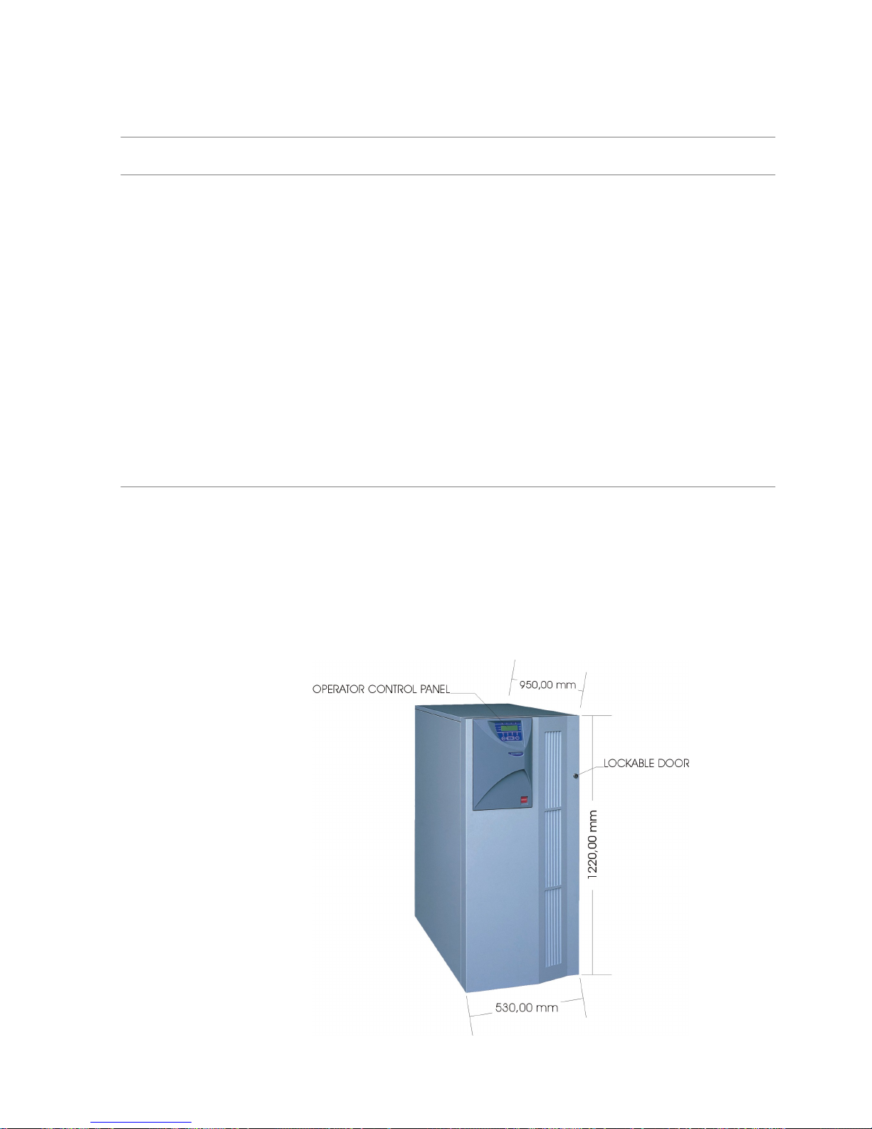
The equipment is constructed around a steel frame with removable panels. The door which can be seĆ
cured with a key is opened to give easy access to the input, bypass, output, reserve line circuit breakers
and battery C.B. fused switch, protecting them from accidental operation.
A string LED and control panel on the front of the cabinet permits the operator to monitor the UPS.
The cabinet houses both the power components and the batteries.
It is carried on four wheels. Jacking feet help to support the UPS, and also prevent it from moving once
it has been wheeled into its final position. These feet are also used to secure the equipment to its shipĆ
ping pallet during transit.
Cooling is by internal fan. Air is drawn in from beneath the UPS and exhausted through ventilation grills
of the front panel. These areas must be kept free of anything that may avoid the air flow into and out of
the unit.
Figure 1-1Front view of cabinet.

Service ManualChapter 1 - Overview
Equipment Construction
1 - 23x3 UPS Overview
Issue 2 - November 2001
1.2.1 - Principle of operation
Normal operation
During normal operation, i.e. when the UPS input supply is present and within specification, both the
converter and inverter sections are active and the automatic byĆpass is turned on to connect the inverter
output to the critical load terminals. The battery fuseĆholder switch is also closed and the battery is thereĆ
fore permanently float charged at the d.c. terminals voltage level.
Mains Failure
If the mains has a failure or is out of tolerance the converter will be supplied from the battery, while the
Inverter will continue to operate for a period of time which depends on the load and the capacity of the
battery. If the mains supply has not returned within this time, the Inverter will go off automatically and
an alarm condition will appear on the UPS operator control panel.
Critical load will not be interrupted in the event of a drop or return of the AC power mains.
Return of power mains
When the mains returns within the required tolerance, the converter will be automatically supplied from
mains, supplying power to the Inverter and recharging the battery at the same time. There will be no
interruption of the critical load.
UPS fault
In the event of an inverter failure, the automatic byĆpass will automatically transfer the load onto the
mains with no interruption. In such an event, request qualified technical assistance.
The load will be transferred with no interruption if the inverter is synchronised with the mains; if this is
not the case, there will be an interruption of some milliseconds.
The intervention of the automatic byĆpass line is shown on the front panel by the yellow led on.
WARNING CAUTION: When the load is being supplied from the bypass line through the automatic byĆ
pass, it is connected directly to the mains supply and is therefore no longer protected
against mains faults.
Maintenance Bypass
A second bypass circuit contained in the UPS cabinet, identified as the 'Maintenance Bypass' line is
included to enable the reserve supply to be made available to the load while facilitating a safe working
environment for carrying out scheduled UPS system maintenance or trouble shooting. The circuit is
manually selected by the Manual Bypass Switch (3) which can be padlocked in the OFF position.
WARNING CAUTION CAUTION: If an automatic circuit breaker device is not present in the input disĆ
tribution panel, there remains a dangerous voltage at the output terminals and also on the
input terminals of the UPS module that is switched off.
Note: The load is not protected from mains aberrations when operating on the
maintenance bypass mode.

Service Manual Chapter 1 - Overview
Equipment Construction
1 - 33x3 UPS Overview
Issue 2 - November 2001
Figure 1-2Split Bypass" configuration
UPS
Output
UPS
Input
Battery
UPS
Split
Bypass
Link
1.2.2 - UPS Power Configuration
Common Bypass
The UPS is factory set to operate in the Common Bypass" configuration. Split Bypass links shown
in Figure 1-2 connect the Input Mains supply to the Reserve Input (Bypass) line creating a common
input. A separate Reserve Input is therefore not required.
Split Bypass
To configure the with a Split Bypass input, the Split Bypass links shown in Figure 1-2 are removed
by the commissioning engineer. In the Split Bypass" configuration the static bypass line is connected
by a separate power switch to a dedicated `bypass' power source which also feeds the maintenance
bypass line. Where a separate power source is not available the Reserve and Converter input supply
connections would be linked together.
With the exception of the maintenance bypass switch (3), all the isolators shown must be closed during
normal UPS operation.
1.2.3 - Battery fuses switch
The battery is connected to the d.c. bus through a battery fuses switch (5) fitted inside the UPS cabinet


2 - 13x3 UPS Installation
Issue 2 - November 2001
Chapter 2 - Installation
2.1 - Installation (Mechanical)
2.1.1 - Preliminary Checks
Before installing the UPS hardware the following preliminary checks must be carried out:
1. Verify that the UPS room satisfies the environmental conditions stipulated in the equipment
specification, paying particular attention to the ambient temperature and air exchange
system.
Material admittance
1. Remove any packaging debris, then visually examine the UPS and battery equipment for
transit damage, both internally and externally.
Report any such damage to the shipper immediately.
2. Ascertain that the material supplied corresponds with that on the freight bill.
Identification
The equipment supplied is provided with an adhesive identification label placed on the UPS rear panel
reporting type of UPS model and power.
The cases used to transport the equipment must be unpacked as specified by the procedure stated
below.
Packing material removal
During this operation observe the indications (FRAGILE, UP) printed on the case to avoid damaging the
UPS
To remove the packing material proceed in the following manner:
1. Place the equipment on the floor as instructed on the outer case (UP, DOWN).
2. Cut the tape and open the flaps at the top of the cardĆboard box.
3. Remove the extruded elements used as protective packing.
4. Position the forks of the lifting truck under the UPS taking care not to damage the UPS
castors and lift it a few centimetres from the floor. Back up the forklift and position the UPS.
Lower to the floor.
Hinet is provided with wheels to allow ease of movement.
5. Retain the packing material.
The original transit packing should be used if the equipment is be returned to the
maintenance centre, or moved to another position.
6. Check that the equipment has not been damaged.
Any damage should immediately be reported to the Sales Representative.
7. Locate the four battery fuses. Do not fit at this point.
8. Locate the door key and panel bolt spanner secured on the rear of the UPS. Retain for future
use.
9. The operator manual and communication cable are located behind the hinged front door.
Moving the cabinets
WARNING Ensure that any lifting equipment used for moving the UPS cabinet has sufficient lifting caĆ
pacity.
Ensure that the UPS weight is within the designated surface weight loading (Kg/cm2) of any
handling equipment. See the UPS specification for weight details.
The UPS can be lifted using a fork lift. Take care when using either method not to damage
the UPS castors located on the bottom of the unit.

Service ManualChapter 2 - Installation
Installation (Mechanical)
2 - 23x3 UPS Installation
Issue 2 - November 2001
Locating the unit in the operating position
The UPS cabinets are fitted with castors on the base to allow ease of movement and positioning. When
the equipment has been finally positioned ensure the adjustable feet are set so that the UPS will remain
stationary and stable
Ensure the following considerations are observed when locating the equipment:
a) Easy connection.
b) Enough space to ensure good access when servicing the UPS.
c) Exchange of air sufficient enough to dispel heat produced by UPS.
d) Protection against atmospheric agents.
e) Protection against excessive humidity and very high heat sources.
f) Protection against dust.
g) Compliance with the current fire prevention regulations.
h) Operating environment temperature is within +20° C and +25° C.
The batteries are at maximum efficiency in this temperature range.
Clearances
Cooling air enters the module through ventilation grills located at the bottom of the cabinet and is exĆ
hausted through the fan grills located on the front panel; you must therefore allow for a minimum gap
of 170 mm behind the unit to allow adequate air flow. Clearance around the front of the equipment
should be sufficient to enable free passage of personnel with the door fully opened.
Raised floor installation
If the equipment is to be located on a raised floor it must be mounted on a pedestal suitably designed
to accept the equipment point loading.
Refer to the base view to design this pedestal.
Cable entry
Cables enter the UPS cabinet from the rear.
UPS Mechanical Characteristics
Rated power kVA 10 15 20 30
Height mm 1220
Width mm 530
Depth mm 950
Weight:
Hinet cabinet 185
with 1 battery strings
275
with 2 battery strings
Kg
365
with 3 battery strings 455
with 4 battery strings 545
Ventilation Ć forced
Airflow full speed
Air flow half speed
m3/h
600
300
Protection grade Ć IP 20
Cable entry Ć Bottom

Service Manual Chapter 2 - Installation
Installation (Electrical)
2 - 33x3 UPS Installation
Issue 2 - November 2001
2.2 - Installation (Electrical)
The UPS requires connection of the power cables once it has been mechanically installed. All auxiliary
cables, whether screened or not, should be run separate from the power cables in metal conduits, or
metal ducts electrically bonded to the cabinet metalwork to which they are connected.
2.2.1 - Power Cabling
WARNING BEFORE CABLINGĆUP THE UPS, ENSURE THAT YOU ARE AWARE OF THE LOCATION AND
OPERATION OF THE EXTERNAL ISOLATORS THAT CONNECT THE UPS INPUT/BYPASS
SUPPLY TO THE MAINS DISTRIBUTION PANEL.
CHECK THAT THESE SUPPLIES ARE ELECTRICALLY ISOLATED, AND POST ANY NECESSĆ
ARY WARNING SIGNS TO PREVENT THEIR INADVERTENT OPERATION.
2.2.2 - Power Cable connections
The cable connection terminal block shown in Figure 2Ć1 is located at the rear of the cabinet.
1. Prepare the power cable ends and locate in the lower terminals of the terminal block.
2. Connect Input Mains to terminals 14 (U1), 15 (V1), 16 (W1) & 17 (N1).
Caution When preparing the power cables for connection, provide sufficient spare cable to allow
the UPS to be moved if necessary from it's normal operating position for servicing access.
Spare cable can be coiled beneath the unit.
3. Tighten the terminal block lower securing screws and check that each cable is secure.
4. Connected the UPS Output power cables to terminals 1 (U2), 2 (V2), 3 (W2) & 4 (N2) as
shown in Figure 2Ć1.
5. Secure the cables to the cable securing bar adjacent to the terminal block using appropriate
cable clamps.
Note: If connecting a battery to the External Battery input connections ensure
that connections are made with the correct polarity.
Split Bypass Configuration
If the UPS is to operate with a separate Reserve Input (Bypass) supply.
1. Connect the power connections for the Bypass to terminals 10 (U3), 11 (V3), 12 (W3) & 13
(N3)
2. Connect the Input Mains to terminals to 14 (U1), 15 (V1), 16 (W1) & 17 (N1) as shown in
Figure 2Ć1.
Caution When the UPS is to be operated in the Split Bypass" configuration, the Split Bypass shortĆ
ing links must first be removed by the Commissioning Engineer before Power is applied
to the unit.
Note: The maximum cable size that can be connected to the UPS power
terminal block is 25mm
2

Service ManualChapter 2 - Installation
Installation (Electrical)
2 - 43x3 UPS Installation
Issue 2 - November 2001
Figure 2-1Connections to distribution Terminal Block.
PE1U22V23W24N25+6+7ć8ć9U310V311W312N313U114V115W116N117PE
18
Ground
Ground
UPS Output Ext. Battery Input Reserve Input (Bypass) Input Mains
1.. Ground (ground lead for load connection) 2.. Input reserve (Bypass) phase U3
3.. Output phase U2 4.. Input reserve (Bypass) phase V3
5.. Output phase V2 6.. Input reserve (Bypass) phase W3
7.. Output phase W2 8.. Input Reserve (Bypass) Neutral N3
9.. Output Neutral N2 10.. Input Mains phase U1
11.. Battery Positive (ext. Battery input) 12.. Input Mains phase V1
13.. Battery Positive (ext. Battery input) 14.. Input Mains phase W1
15.. Battery Negative (ext. Battery input) 16.. Input Mains Neutral N1
17.. Battery Negative (ext. Battery input) 18.. Ground (Incoming ground wire from UPS
input mains connected to this terminal)
Figure 2-2 Cable Securing Bar
Cable Securing Bar

Service Manual Chapter 2 - Installation
Installation (Electrical)
2 - 53x3 UPS Installation
Issue 2 - November 2001
2.2.3 - Safety Earth
The safety earth busĆbar is located near the UPS output terminals. The safety earth cable must be conĆ
nected to the earth terminal and bonded to each cabinet in the system.
All cabinets and cable trunking must be earthed in accordance with local regulations.
WARNING FAILURE TO FOLLOW ADEQUATE EARTHING PROCEDURES CAN RESULT IN ELECTRIC
SHOCK HAZARD TO PERSONNEL, OR THE RISK OF FIRE, SHOULD AN EARTH FAULT
OCCUR.
BEFORE ANY OTHER CABLE CONNECTION THE PE SAFETY CONDUCTOR SHALL BE
CONNECTED
2.2.4 - Protective devices
Protection against earth faults (RCD devices):
In the event of a differential (RCD) device being installed upstream of the input supply, the transient and
steady state earth leakage currents that are produced during startĆup of the UPS must be taken into acĆ
count.
The presence of an RFI suppression filter inside the UPS, determines a residual earth current no greater
than 500 mA.
Residual current circuit breakers (RCCB) must be sensitive to d.c. unidirectional pulse (class A) in the
mains and insensitive to transient current pulses.

Service ManualChapter 2 - Installation
Battery Installation
2 - 63x3 UPS Installation
Issue 2 - November 2001
2.3 - Battery Installation
All UPS models are normally shipped with an internal battery fitted, therefore a thorough check
of the battery installation is required before applying power to the unit. The battery capacity, number of
cells and installation is dependent on the unit power rating and autonomy option ordered. A full break
down of the different battery configurations can be found in the Specification on preliminary page Ćxiii.
In addition to the standard battery fitted to the UPS extra strings may be added (to a maximum of 4) to
upgrade the battery autonomy. Full fitting instructions for the battery upgrade are included with each
kit, however this information has been also included in this section of the manual for continuity.
The UPS may also have an extended battery option to be fitted either in a separate or atĆ
tached cabinet, therefore the same basic checks apply.
Before
2.3.1 - Battery Safety
WARNING THE BATTERY CHAIN IS A HIGH VOLTAGE ENERGY SOURCE. WHICH CAN BE VERY DANĆ
GEROUS GIVING A POTENTIAL RISK OF SHOCK OR BURNS.
GREAT CARE SHOULD BE EXERCISED AT ALL TIMES WHEN WORKING WITH BATTERIES.
S Special care should be taken when working with the batteries associated with this
equipment.
S When connected together, the battery terminal voltage will exceed 380Vdc and is
potentially lethal.
S Eye protection should be worn to prevent injury from accidental electrical arcs.
S If a battery leaks electrolyte, or is otherwise physically damaged, it should be
placed in a container resistant to sulphuric acid and disposed of in accordance with
local regulations.
S If electrolyte comes into contact with the skin the affected area should be washed
immediately.
2.3.2 - Battery Installation Check
1. Gain access to the battery safety cover by first opening the front hinged door.
a) Disconnect the Earth bonding cable from the safety cover.
b) Remove the two top M6 retaining bolts.
c) Release the two bottom retaining bolts and lift the cover from the UPS.
2. Remove the Main Switch Cover held by four M6 retaining bolts.
3. Carefully ease the cover away from the control switches.
Note:Each battery string are held in 3 trays positioned as
shown in Figure 2Ć3, up to four strings can be fitted dependent on model.
4. Check the battery security in each tray.
5. Check that the FastĆon connecters to each battery are secure and that each connector is
correctly positioned on the battery terminals.
6. Check that the battery linking connectors are correct for each tray.
7. Check that the +ve cable from lower battery tray connector is connected to the correct
battery fuse, as shown in Figure 2Ć4
8. Check that the ćve battery from the top battery tray connector is secured to the common
battery ćve connection bar.
Service Manual Chapter 2 - Installation
Battery Installation
2 - 73x3 UPS Installation
Issue 2 - November 2001
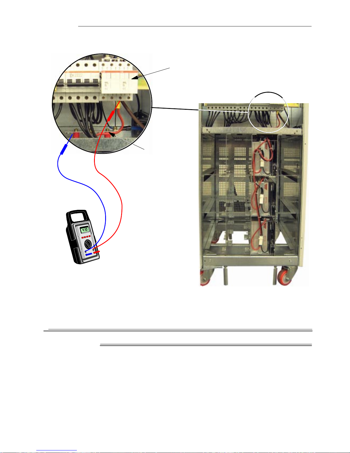
Figure 2-3 Battery Tray Installation for one battery string
Battery Fuses (shown removed)
Battery Earth Bar
Battery String Voltage Check
Note: Battery fuses are removed for transit and should only be fitted by the
commissioning engineer. The fuses can be found with the User manual, in
the document pocket on the battery safety cover.
Battery String Voltage check
1. Ensure the battery fuses are removed from the switched fuse holders.
Warning Do not fit the battery fuses into the fuse holders or close the fuse holders.
2. With a DVM set to a DC range of above 450V, check for each individual battery string
voltage. This voltage for a serviceable battery should be between +385V and +416V DC.
3. Measure the battery string voltage from the lower connecting screw of the appropriate fuse
holder and the battery ćve connection bar. As shown in Figure 2-3
4. If a voltage of less than +385V is recorded reĆcheck the battery connections and reĆtest the
string voltage.
Note: A measured voltage substantially less then +385V DC may point to a
defective battery block this can be further isolated by disconnecting each
individual tray and carry out a further check of each tray voltage. This
should be grater than 132V for trays of 11 battery blocks and 120V for 10
blocks.
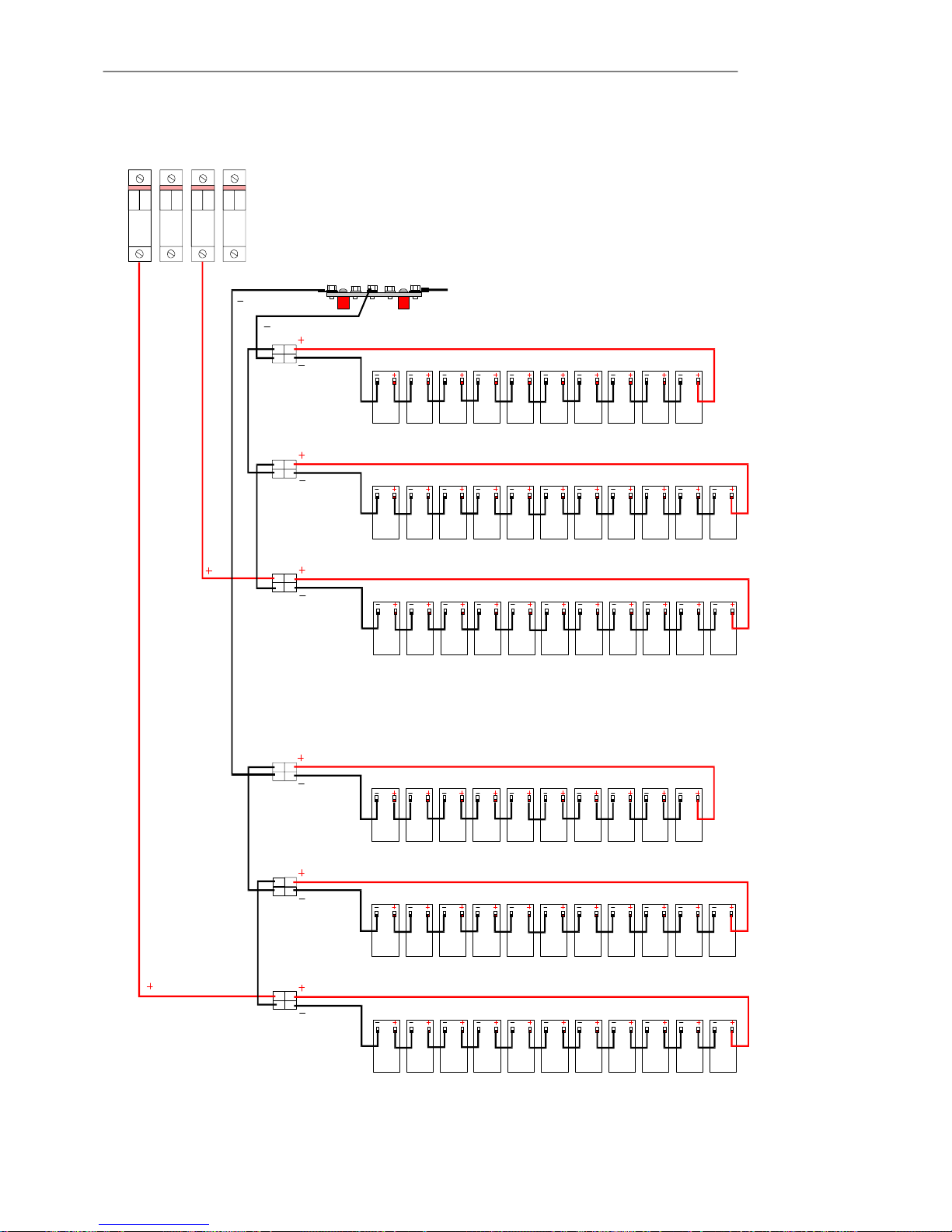
F1 F2 F3 F4
Battery Fuses
Battery ćve Connection Bar
Battery String 3 Top Battery Tray (10)
Battery String 3 Middle Battery Tray (11)
Battery String 3 Bottom Battery Tray (11)
CN1
CN2
CN3
Note: Battery strings 1 & 3 shown connected
Battery String 1 Top Battery Tray (10)
Battery String 1 Middle Battery Tray (11)
Battery String 1 Bottom Battery Tray (11)
CN1
CN2
CN3
Service ManualChapter 2 - Installation
Battery Installation
2 - 83x3 UPS Installation
Issue 2 - November 2001
Figure 2-4 Battery Cable Connections for one string
Service Manual Chapter 2 - Installation
Battery Installation
2 - 93x3 UPS Installation
Issue 2 - November 2001
2.3.3 -Installing the Battery Upgrade Kit
Note: Installation of a battery upgrade kit must only be carried out by a suitably
qualified, manufacturer approved engineer.
Kit Contents
Prior to installing the battery upgrade kit thoroughly check the items for damage and ensure that they
are in a serviceable condition.
Check that the battery kit contains the following items:
Item Description Part Nº Quantity
Mylar insulating sheet CM 0319 3
Battery tray CM 0470 3
Battery retaining bracket CM 0743 3
Lexan protection CM 0101 3
Battery cable harness OS 001 1
Adhesive foam strip ? ć
Cable holder self adhesive ? 9
Label `High Voltage' ? 3
Note: The 32 battery blocks are not included in the upgrade kit Part Nº
BATTCABLE, but are supplied separately as Battery Kit Part Nº
INTBATT.
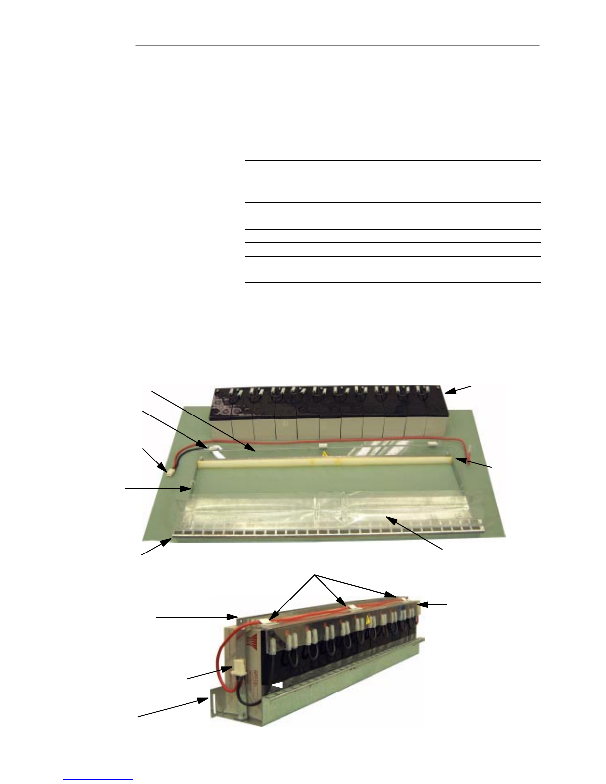
Figure 2-5 Battery Tray Assembly
Mylar Insulating Sheet
Battery Blocks
(links fitted)
Lexan protection strip
Cable Holder
Battery Tray
Battery Cable
Retaining
Bracket
Foam Strip
Battery Tray
Mylar Insulating Sheet
(fold to fit batteries)
Battery Cable Connector
(Secure to retaining
bracket with cable tie)
Retaining Bracket
Cable Holder
Lexan protection strip

Service ManualChapter 2 - Installation
Battery Installation
2 - 103x3 UPS Installation
Issue 2 - November 2001
Battery Tray Assembly
1. Place the Mylar insulation strip on to the battery tray.
2. With a DVM check each individual battery block terminal voltage is within 12.5V to 13.0V.
Voltages measured below this may indicate a defective battery block. Refer to `Battery
Maintenance' on Page 6Ć5 Chapter 6 `Maintenance' for information on battery testing.
3. Fold the mylar insulation to fit the batteries and place the 11 battery blocks on to the battery
tray, as shown in Figure 2-5
(Note 10 battery blocks are fitted to the top battery tray.
4. Stick the adhesive foam strip to the battery fixing bracket.
5. Screw the battery retaining bracket to the battery tray.
Connect the batteries using the short battery interconnecting links.
6. Fit the lexan protection to the battery fixing bracket.
7. Place the three adhesive cable retaining clips to the lexan insulating strip, one in the middle
and one at each end.
8. Identify the cable Anderson type connecter supplied with a red and black interconnecting
cable and connect the red cable to the remaining +ve battery connection and the black
cable to the ćve battery connection.
9. Secure the cables in the cable retaining clips.
10. Secure the red cable to the battery retaining bracket at the rear of the assembled battery tray
using a cable tie supplied.
11. Stick the `High Voltage' label to the lexan insulating strip.
Repeat the above procedure for the remaining two battery trays.
Note: The upper battery tray is fitted with 10 batteries.
Battery String Connection
1. Ensure that the UPS has been powered down.
Note: When positioning the battery trays in the UPS, slight downward pressure
may be required on the front of the tray to clear the chassis metalwork at
the rear.
2. Fit the lower battery tray of 11 batteries to the lower position and secure using the battery
tray retaining bolt.
3. Fit the second battery tray of 11 batteries to the middle position and secure using the battery
tray retaining bolt.
4. Fit the upper battery tray of 10 batteries to the top position and secure using the battery tray
retaining bolt.
5. Refer to the schematic diagram (Figure ) locate the battery string interconnecting links from
the battery cable set.
6. Thread the Red +ve wire of the lower Anderson type cable connector through the
appropriate access hole and connect it to the battery fuse lower cable terminal.
Note: Fuse F1 is used for the first battery string, F2 for the second etc.
7. Thread the Black ćve wire of the top Anderson type cable connector through the appropriate
access hole and connect it to the ćve battery connection bar cable stud.
8. Connect the wiring harness connectors to the battery tray Anderson connectors.
a) CN1 to the top battery tray.
b) CN2 to the middle battery tray.
c) CN3 to the lower battery tray.
9. Secure the Anderson type battery connectors to the battery retaining bracket using the cable
ties supplied with the kit.
 Loading...