

Page 1

Foreword----------------------------------------------------------------------------------------
10-2
Breaking in Your New Machine------------------------------------------------------------
10-3
Operation---------------------------------------------------------------------------------------
10-4
General Locations and Specifications------------------------------------------------------
10-4
Instruments, Switches and Pilot Lamps----------------------------------------------------
10-5
Check before Starting-------------------------------------------------------------------------
10-12
Operation of Grader---------------------------------------------------------------------------
10-16
Operation of Work Equipment---------------------------------------------------------------
10-23
Reversing and Replacement of Cutting Edge and End Bit------------------------------
10-29
Changing Tires--------------------------------------------------------------------------------
10-30
Driving Along Road--------------------------------------------------------------------------
10-32
Towing------------------------------------------------------------------------------------------
10-33
Cold Weather Operation----------------------------------------------------------------------
10-34
Memo--------------------------------------------------------------------------------------------
10-36
Periodic Maintenance-------------------------------------------------------------------------
10-37
Maintenance Table----------------------------------------------------------------------------
10-38
Oil filler and Level Gauge Positions-------------------------------------------------------
10-45
Every 50 hours service-----------------------------------------------------------------------
10-46
Every 100 hours service----------------------------------------------------------------------
10-46
Every 250 hours service----------------------------------------------------------------------
10-47
Every 500 hours service----------------------------------------------------------------------
10-57
Every 1000 hours service---------------------------------------------------------------------
10-60
Every 2000 hours service---------------------------------------------------------------------
10-66
Every 4000 hours service---------------------------------------------------------------------
10-68
When Required---------------------------------------------------------------------------------
10-69
Trouble Shooting Guide----------------------------------------------------------------------
10-74
Service Meter----------------------------------------------------------------------------------
10-78
Machine and Engine Serial Numbers-------------------------------------------------------
10-79
Fuel, Coolant and Lubricants----------------------------------------------------------------
10-80
Safety and Operation------------------------------------------------------------------------
10-81
Safety Hints------------------------------------------------------------------------------------
10-82
Precautions for Maintenance-----------------------------------------------------------------
10-90
Handling of Battery---------------------------------------------------------------------------
10-95
Hanging Up------------------------------------------------------------------------------------
10-97
Transportation---------------------------------------------------------------------------------
10-98
Storage------------------------------------------------------------------------------------------
10-99
Powertrac PT130 Motor Grader
Safety Operation & Maintenance Manual
10- 1
Page 2

FOREWORD
This manual describes procedures for operation, handling, lubrication, maintenance,
checking, and adjustment. It will help an operator or anyone to make the machine realizing a
good performance through effective, economical and safe operation and maintenance.
Please read this manual carefully BEFORE operating the machine.
Please continue studying this manual until proper operation is completely reinforced into
personal habit.
This manual describes the basic techniques. Skill is performed as the operator or anyone
get the correct knowledge and performance of the machine.
Operation, inspection and maintenance should be carefully carried out, and the safety
must be given the first priority. Safety precautions are indicated with “ ” marks and
technical precautions with “★” marks in this manual. The safety information contained
in this manual is intended only to supplement safety codes, insurance requirements, local
laws, rules and regulations.
Some photographs and illustration pictures are different from your machine as technical
improvement is continuously reflected on it. Revision to up-to-date manual’s content is
performed in later editions.
This operation and maintenance manual may contain attachment and optional equipment
that are not available in your area. Please contact us for those items you may require.
About engine and transmission instructions in this manual, if thy are different from the
“ENGINE OPERATION INSTRUCTION” and the “TRANSMISSION OPERATION
INSTRUCTION” provided for your machine, the latest operation instructions should be
taken as the standard.
Materials and specifications are subject to change without notice.
10- 2
Page 3

BREAKING IN YOUR NEW MACHINE
Each machine is carefully adjusted and tested before shipment. However, a new machine
requires careful operation during the first 100 hours to break in the various parts.
If a machine is subjected to unreasonably hard use at the initial operation stage, the potential
of performance will prematurely deteriorate and the service life will be reduced. A new
machine must be operated with care, particularly with regard to the following items:
After starting, let the engine idle for 5 minutes to allow proper engine warm-up prior to
actual operation.
Avoid operation with heavy loads or at high speeds.
Sudden starting or acceleration, unnecessarily abrupt braking and sharp turning should be
avoided.
If the machine is delivered without any cooling water in the radiator, flush the cooling
system with ample clean water to clean the system, then fill the radiator with cooling
water.
★ When checking, adding or changing the cooling water, fuel or lubrication oil, be sure not
to let any dust or dirt get in.
★ When replacing oil filters elements (cartridges), check their interiors for dirt and dust. If
heavily collected, check for possible cause before starting operation.
★ Hours of operation are indicated by the service meter.
10- 3
Page 4

1. Head Lamp
2. Blade Lift Cylinder
3. Rear Tire
4. Articulation Cylinder
5. Drawbar Side Shift Cylinder
6. Blade
7. Front Tire
Machine Model
713H
Performance
1.Travel Speed (km/h)
Forward
53.4
Reverse
37.8
2. Min. Turning Radius (m)
6.6
3. Grade Ability(%)
25
4. Stability(°)
35
Operating Weight
(Kg)
12000
Engine
1. Model
DONGFENG CUMMINS 6BT5.9-C130
2. Flywheel Horsepower (kw/r/min)
97/2200
General Locations and Specifications
10- 4
Page 5
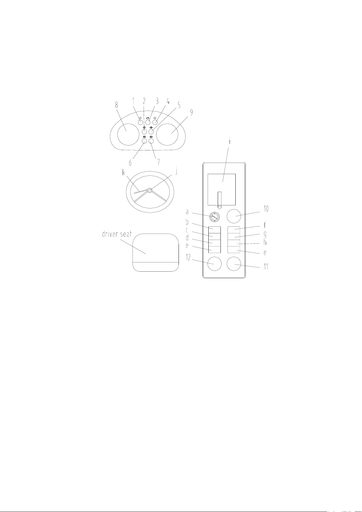
1. Left Turn Signal Lamp
Green light. When the steering lever is set on the left turning position, this
lamp lights up.
2. Low Oil Pressure Lamp
Red light. When the oil pressure is low,this lamp lights
up,please check, Don’t operate the grader when this lamp lights
up.
3. Battery Charging Lamp
Red light. It warns drivers: When the engine is running, the charge
system is not in normal or the chopper switch is not turned off after the
engine stop.
★ If this lamp lights up, check the charge system (when the engine is
running), or check if the chopper switch is not turned off (when the
engine stops).
4. Right Turn Signal Lamp
Green light. When the steering lever is set on the right turning position,
this lamp lights up.
Instructions, Switches and Pilot Lamps
1. Meters and Pilot Lamps
10- 5
Page 6

5. Stall Pressure Lamp
Red light, When the stall pressure is low,this lamp lights up,please
check, Don’t operate the grader when this lamp lights up.
6. Brake Lamp
Red light。When the foot brake is used, this lamp lights up.
7. Hand Brake Pilot
Lamp
Red light. When the hand brake lamp is used, this lamp lights up.
★ Don’t operate the grader when this lamp lights up.
8. Fuel Level Gauge
Indicate the fuel level。
9. Engine Cooling Water
Temperature Gauge
This gauge indicates the cooling water temperature of engine.
During operating, the needlepoints to the green range, it indicates the water
temperature is normal. When the needle points at the red range, stop the
machine and run the engine with no load at midrange speed until the needle
returns to the green range.
★ If the needlepoints in the red range again and again, the fan vane should be
checked up.
10. Service Meter
This meter shows the total working hours of the engine. The service meter
advances once the engine has run even if the grader doesn’t travel.
11. Oil Temperature Gauge
for Torque Converter and
Transmission
This gauge indicates the oil temperature of the torque converter and the
transmission system.
In working, when the needle points at the green range, it indicates the oil
temperature is normal. When the needle points at the red range, stop the
operation and run the engine with no load at midrange speed until the needle
returns to the green range.
12. Engine Oil Pressure
Gauge
This gauge shows the oil pressure of the engine.
While the grader is working, the pointer in the green zone means that
the pressure is normal, if in the red zone and the engine oil pressure
gauge lights up, you need to stop and check it.
2. Switches and Levers
10- 6
Page 7

a. Starting switch
This switch is used to start or stop the engine.
OFF: At this position, the key can be inserted or removed. When the switch is turned
to this position, the electrical circuits are cut off.
On: When the switch is turned to this position by clockwise, the charging circuit and
the lamp circuit are electrified.
START: The starting motor is started revolution by turning the switch clockwise
further for one step, and also the engine is started. Releasing the key will
automatically return the key to the position ON. So, you should release the key at
once after the engine is started.
★ Never leave the starting switch key in “OFF” position while the engine is
running.
★ The starting switch does not control the cab electrical circuits (such as fan,
dome lamp, wipers, etc.)
10- 7
Page 8

b. Head Light Switch
When this switch is pressed at low position, the headlamps light up as close
beam.
When this switch is pressed at high position, the headlamps light up as far
beam.
c. Rear Light Switch
When this switch is pressed at low position, the rear lamps light up as close
beam.
When this switch is pressed at high position, the rear lamps light up as far
beam.
d. Working Lamp Switch
When the switch is pressed at the ON position, the front and rear working
lamps light up.
e. Wiper Switch
When the switch is pressed at the ON position, the wiper will operate.
When the switch is pressed at the OFF position, the wiper will stop working
and restore.
f. Instrument Lamp Switch
When the switch is pressed, all instrument lamps, the front and rear side
marker lamps light up.
g.Double Jump Switch
When the grader fault and stop to check it,press the switch to
the open position,left and right steering lamps shine at the same
time。
h. Fan Switch
When the switch is pressed at the ON position, the fan will run.
i. Transmission Lever
This lever controls the transmission with the forward/reverse gears or the
six speeds for forward and the three speeds for reverse.
j. Horn Switch
When the button in the center of the steering wheel is pressed, the horn will
sound.
k. Turn signal Lamp Level
This lever operates the turn signal lamps.
①The joystick forward:Right turn。
②The joystick back:Left turn。
Control Lever and Pedals:
10- 8
Page 9
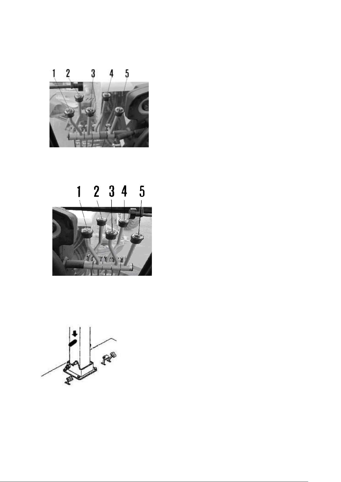
1. Work equipment control lever:
These levers operate the work equipment.
1. Left blade lift lever
2. Ripper control lever(OPTIONS)
3. Blade side shift lever
4. Power tilt control lever
5. Blade rotation control lever
These levers operate the work equipment.
1. Draw bar side shift lever
2. Articulation control lever
3. Right blade lift lever
4. Front wheel leaning lever
5. Scarifier lift lever(OPTIONS)
2. Steering Post Tilt Lever
Turn the ratchet wheel, and the steering post can be tilted.
(the most lean 25°) Turn the pin of the handle, and achieve
replacement.
10- 9
Page 10
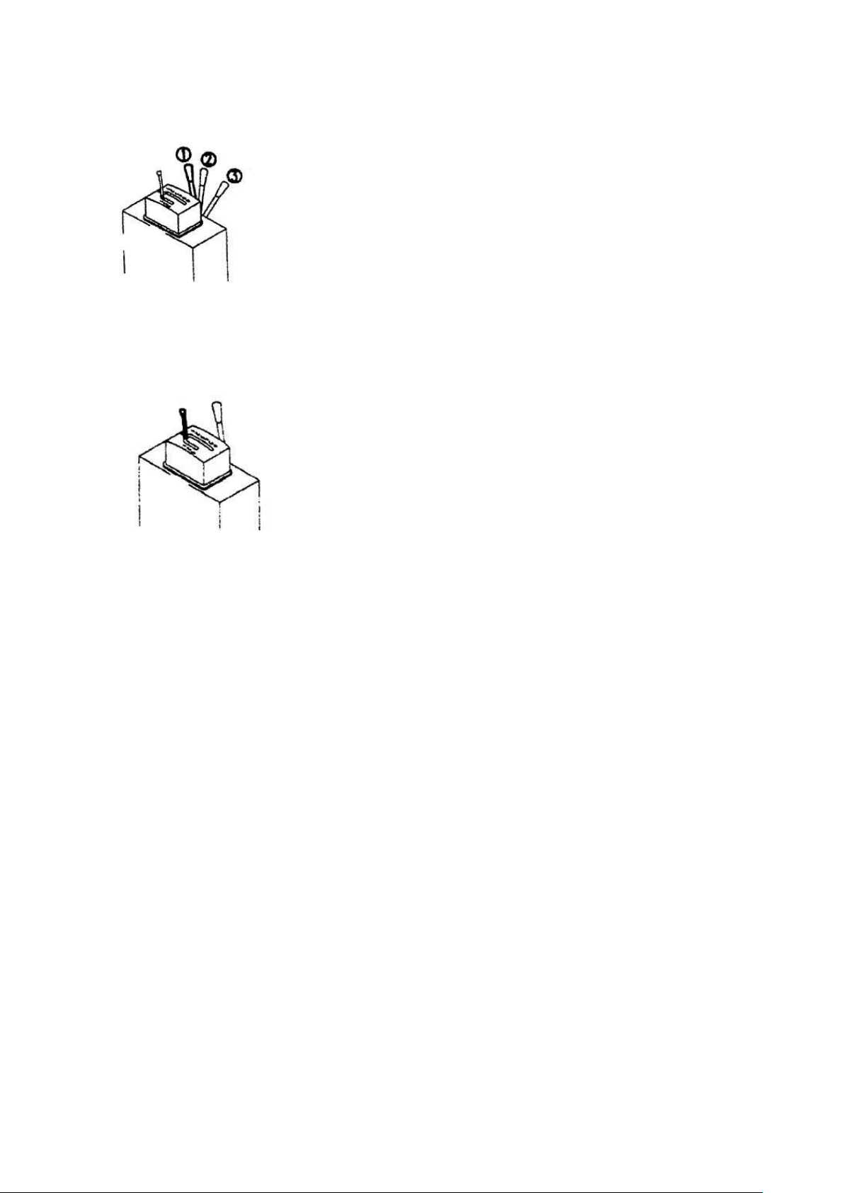
3. Fuel Control Lever
This lever adjusts the engine speed and output.
① Engine stop position: Push the lever fully.
② Low idling position: Pull the lever from engine stop position ① until you
feel the operation force falls off.
③ High idling position: Pull the lever from low idling position ② fully.
★ Use the fuel control lever only during actual work. When running the
machine along a road, use the accelerator pedal.
4. Gear Shift Lever
This lever is used to change the transmission gear. Simply moving
this lever to desired speed position could perform 6-speed forward
and 3-speed reverse transmission. When the lever is left placed in any
position other than neutral, the engine is prevented from starting.
When the lever is moved to a reverse position, the back up buzzer
sound.
5. Accelerator Pedal
This pedal controls the engine speed and output. The engine speed
can freely controlled between low idling and full speed.
If the pedal is raised from low idling position, the engine will stop.
6.Brake Pedal
The brake is applied on the four rear wheels when this pedal is
depressed.
▲ Do not put your foot on this pedal unnecessarily.
10- 10
Page 11
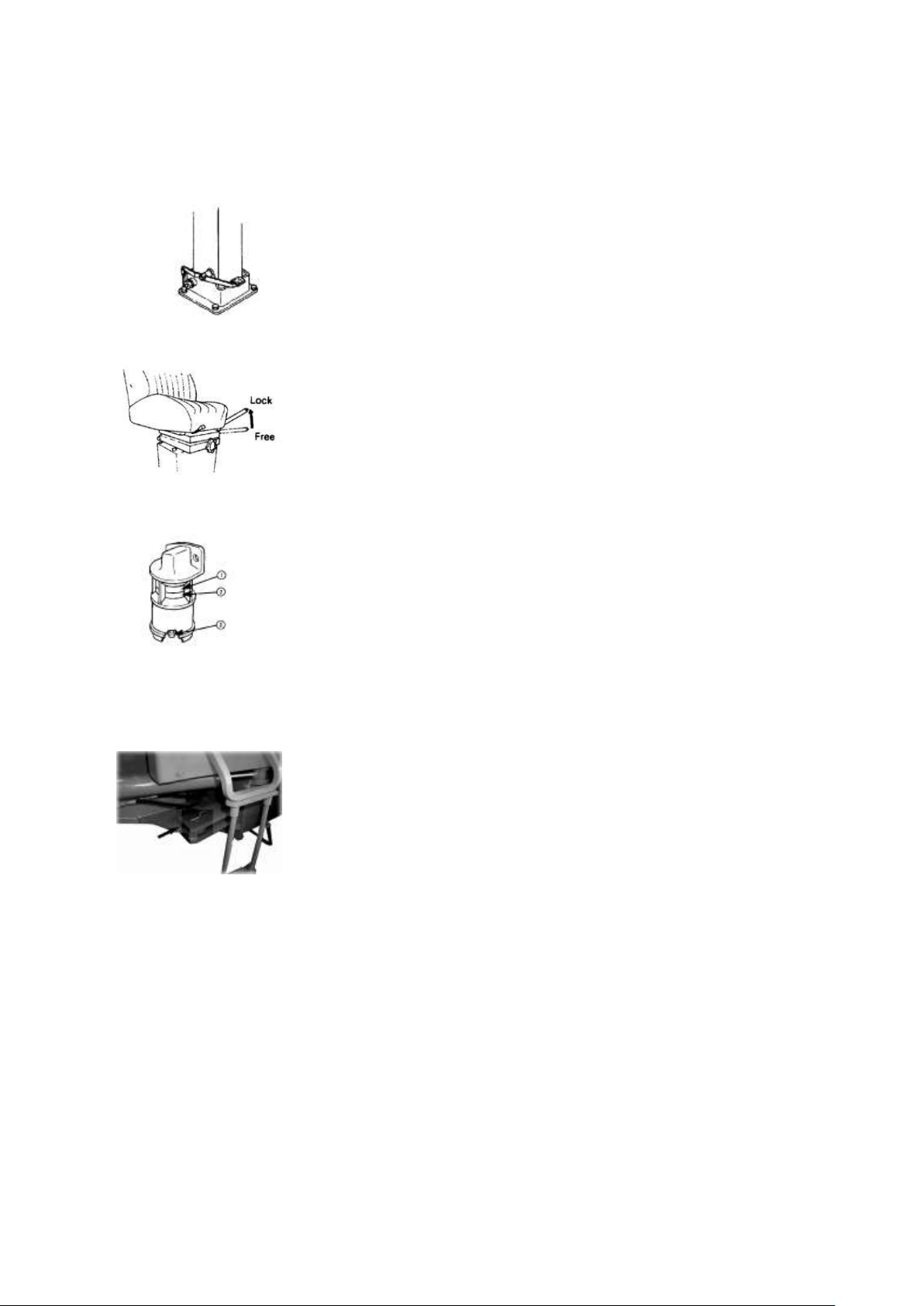
7.Pedal for Bank Lock-pin
Control
This pedal is used for controlling the blade to the bank cut position and
shoulder reach position.
8.Parking Brake Lever
The brake is applied to the output shaft of the transmission by pulling this
lever to the limit.
▲ When parking or leaving the machine, be sure to apply the parking
brake.
Dust Indicator
This device indicates clogging of the air cleaner element. When red
position ② appears in the transparent part of this indicator①, the element
is clogged. Immediately clean the element.
After cleaning, push the indicator button ③ to return the red piston to the
original position.
Articulate Lock Pin
This pin is used to lock the front and rear frame to prevent the machine
from bending when the machine is serviced or transported.
▲ Always use this lock pin when servicing or transporting.
▲ Operating the articulation system when traveling, always
remove the lock pin.
10- 11
Page 12
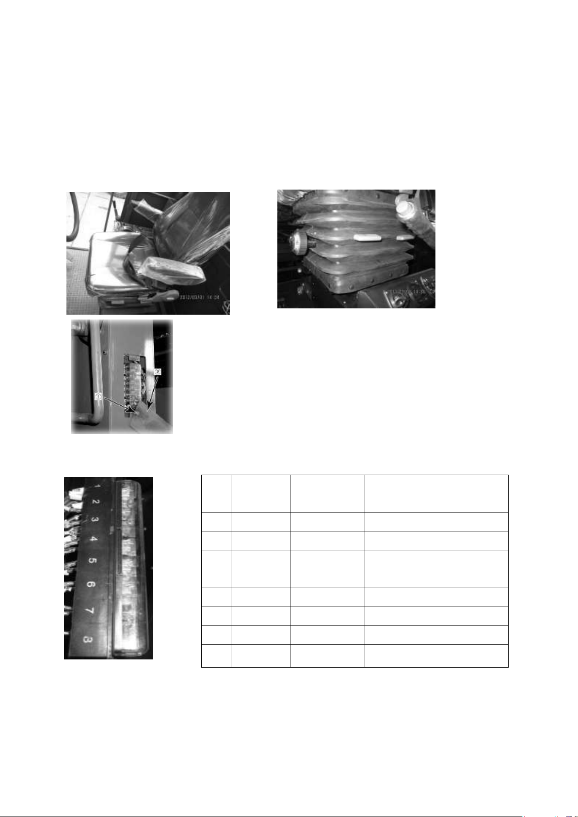
Operator’s Seat
According to the instructions of the seat adjustment
handle,adjust the seat forward and backward, up and down to the
appropriate position 。
Fuse Box
The fuses protect the electric devices and wiring from burning
out. If any fuse is rusted or coated with white powder, replace it.
Loosen the bolt ① and remove the cover ②.
★ Replace a fuse with another of the same capacity.
▲ Before replacing a fuse, be sure to cut off the chopper switch.
Fuse Arrangement and
Circuit
No.
Terminal
Fuse
Capacity
Circuit
①
80
30A
Air-condition
②
20
20A
Horn, turn lamp
③ 8 20A
Starting, Instrument
④
63
20A
Cab ⑤ 15
20A
Head lamp and back lamp
⑥
60
20A
Reverse, brake
⑦ 7 20A
Gauge lamp、Gear selection
⑧ 20A
Spare
10- 12
Page 13
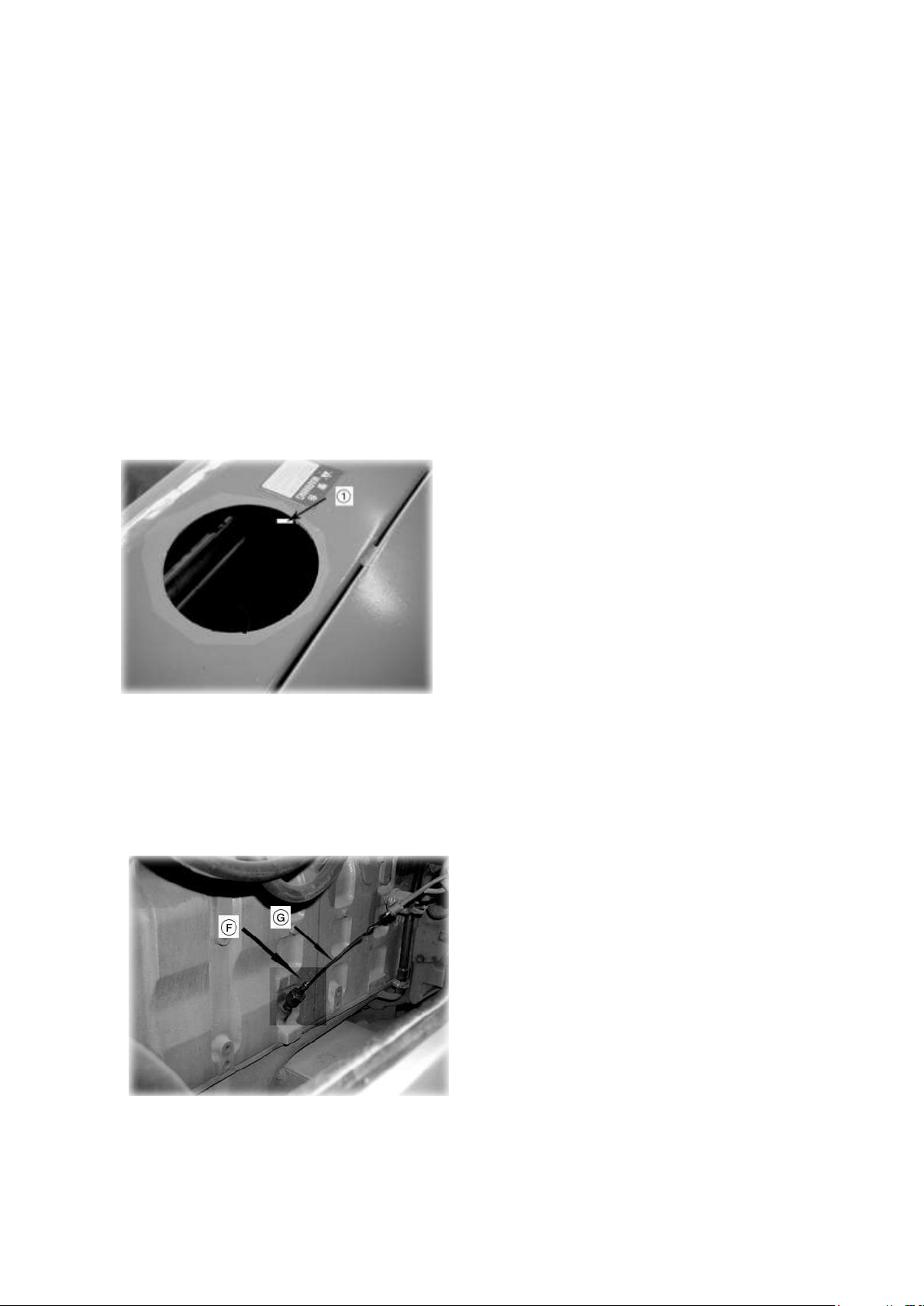
c. Check and Refill Coolant
Remove radiator cap (1) at the top rear of the
machine and check that the cooling water reaches
the area marked by shaded lines. Add water if
necessary.
★ If the volume of coolant added is more than
usual, check for possible water leakage.
▲ Do not remove the cap while cooling water is
hot. Hot water may spout out.
When removing radiator cap, lift the lever to relieve
pressure.
1. Use dipstick (G) to check the oil level.
2. The oil level should be between mark L and H. If
necessary, add oil at oil filler (F).
★ The type of lubricant used depends on the
ambient temperature. Select according to the table
“FUEL, COOLANT AND LUBRICANTS”.
★ When checking the oil level, park the machine
on a flat surface, stop the engine and wait for 15
minutes before checking.
Check before Starting
This check before starting shall never be neglected as troubles are prevented by the check.
a. Walk around the machine body and check whether is any trace of oil or water. In particular, the joint of
high-pressure hose and hydraulic cylinder should be paid special attention. In case leakage is found,
inspect the leaking location and stop the leakage. When leakage is not stopped, you are begged to
request repair to POWERTRAC distributor.
b. Inspect the tightening of bolts and nuts on every section. When loosed ones are found, apply increased
tightening. In particular, attachment positions of air cleaner and muffler should be paid special
attention.
d. Check Oil Level in Engine Oil Pan
10- 13
Page 14
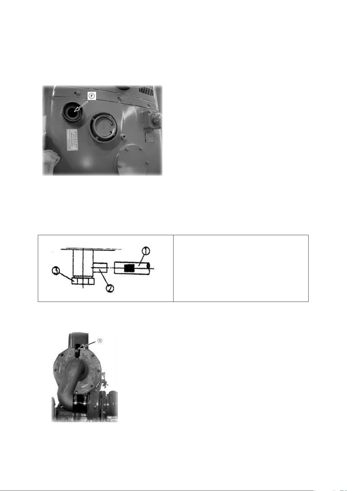
e. Check and Refill Fuel Tank
1. Check the level of the fuel.
2. Top up the tank through the filler (F) after the
day’s work is over.
★ A clogged cap breather hold may stop the fuel
flow to the engine. Check it from time to time and
clean.
★ Fuel Capacity: 270 L.
★ When adding fuel, never let the fuel overflow.
This may cause a fire.
Use the rubber hose (1) with right length to
hitch up the connector (2), then loosen the
drain valve (3) and drain sediment and water
accumulated at the bottom, together with fuel.
When air cleaner element is clogged, the red piston of dust
indicator (1) reaches service level and gets locked. In such
case, clean element referring to the section “WHEN
REQUIRED”. After cleaning element, push button to
return red piston.
f. Drain Water and Sediment in the Fuel Tank
g. Check Dust Indicator
10- 14
Page 15
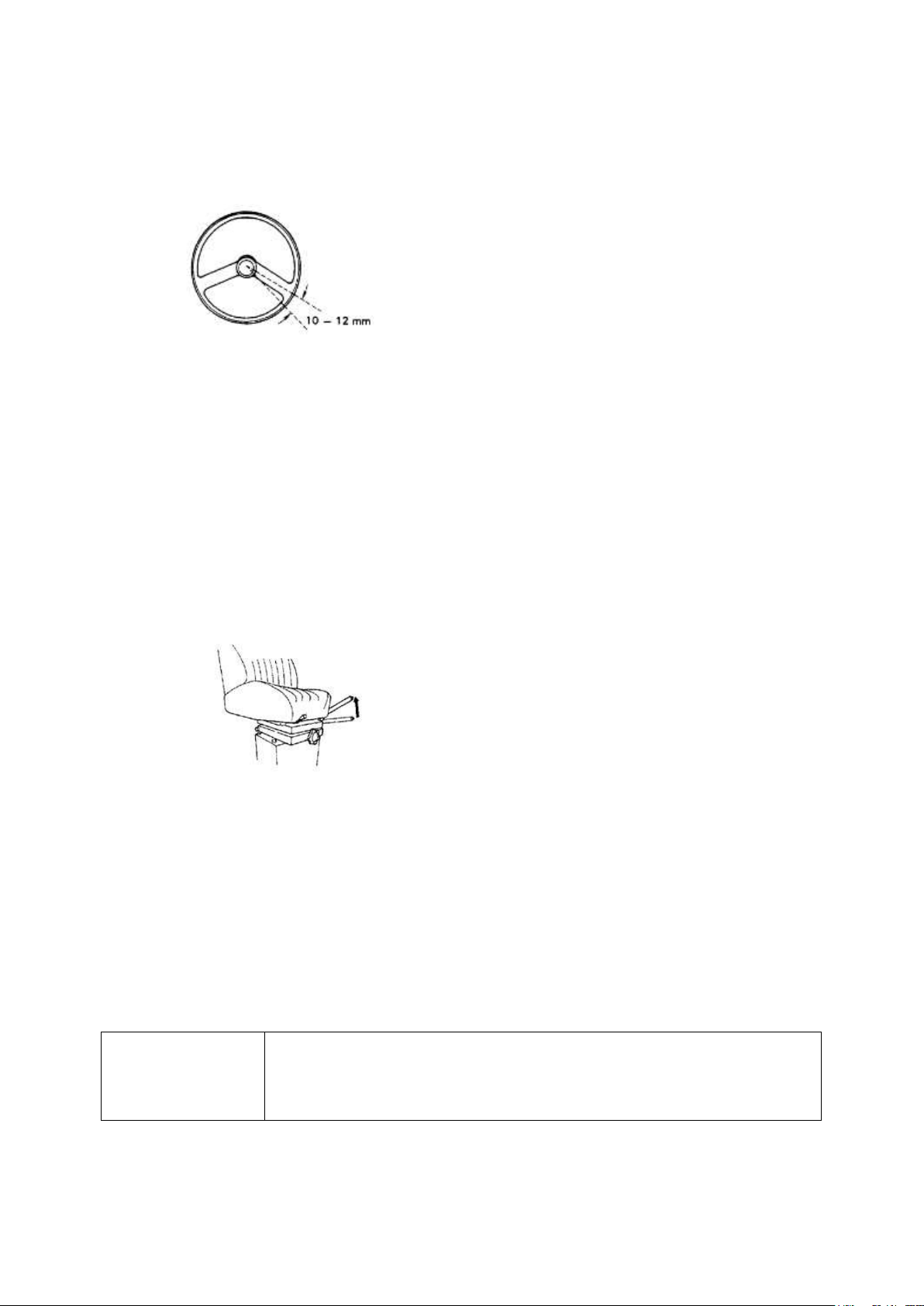
When checking steering wheel play, start engine and
raise front wheels off ground. The standard steering
wheel play is 10~12 mm. Please contact with
POWERTRAC Company if the play is over the
standard or the rotation of the steering wheel is
unusual.
The lever travel is found normal if the brake
is normally applied when the lever grip is
pulled until two or three ratchet clicks are
felt. If six or more clicks are counted before
the parking brake comes into effect, refer to
the Every 250 Hours Service for inspection
and adjustment procedures.
Standard Pressure:
(17.5 – 25 – 12PR L-3)
Front wheel 3.0 kg/cm2
Rear wheel 3.0 kg/cm2
h. Check and Adjust Steering Wheel
i. Check and Adjust Braking Ability
The braking ability is enough if the braking distance is 13 meters or below at the initial speed
of 30 km/h.
★ For insufficient braking ability, refer to Every 250 Hours Service (Wheel Brake).
j. Check Parking Brake for Normal Lever Travel
★ If the machine is started in travel with the parking brake lever left in pulled position, brake
lining will be burnt and braking effect will be greatly deteriorated.
★ If a brake lining is once burnt, normal braking effect will not recover unless very thin,
burnt layer on the lining surface is polished with sandpaper.
k. Check and Adjust Tire Pressure
Make sure the tire and rim is free from wear and damage, and that hub nuts are not loose.
10- 15
Page 16

l. Check lamps for switching, dirt and damage.
m. Check rear view mirror for positioning, dirt and damage.
n. Check horn.
o. Is the color of exhaust gas normal?
p. Do the instruments function normally?
q. Have any defects in which were found during the previous day’s operation been
corrected?
r. Check the door lock for normal function.
s. Check the windshield wiper for normal function.
t. Check electrical wiring
Check for damage of the fuse and any sign of disconnection or short circuits in the electric
wiring. Check also for loose terminals and tighten any loose parts.
Check the following points carefully:
Battery
Starting motor
Alternator
▲ If the fuse is damaged or there is any sign of short circuit in the electric wiring, always
investigate the cause and correct it.
★ Please contact your POWERTRAC distributor for investigation and correction of the
cause.
10- 16
Page 17
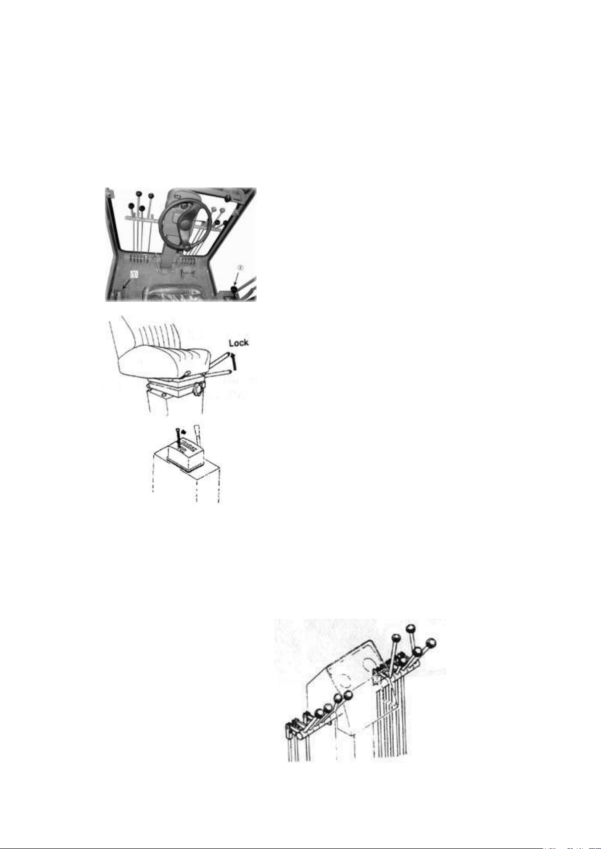
▲ If the control lever is touched by accident, the work
equipment may move suddenly. When leaving the
operator’s compartment, always set the lock lever
securely to the LOCK position.
▲ Before starting the engine, use a damp cloth to wipe
off the dust accumulated on the top surface of the
battery.
1. Before starting the engine, check the position of all
levers.
★ Carry out an initial inspection. (For details of the
inspection, please see Check Before Starting.)
2. Is parking brake lever (1) in the LOCK position?
3. Is gearshift lever (2) in the NEUTRAL position and
locked?
★ Engine will not start unless gearshift lever is in
NEUTRAL.
Before starting the engine
Operation of Grader
4. Is work equipment control lever at the neutral (HOLD) position?
10- 17
Page 18
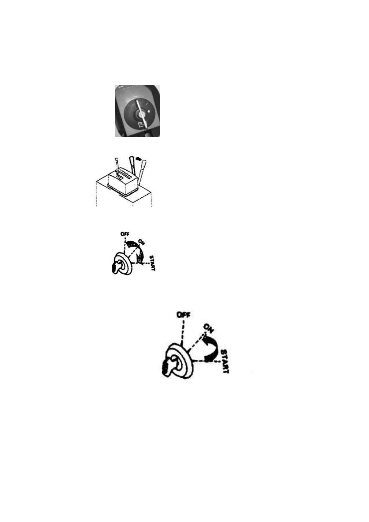
To start the engine:
1. Put the chopper switch to ON position.
2. Put fuel control lever in LOW IDLING position.
3. To start the engine, put the key to START position and turn over the starting motor.
4. As soon as the engine starts, release the starting switch key to allow it to return
automatically to ON position.
★ Do not leave the key in START position for more than 20 seconds.
★ If engine will not start, repeat the starting procedure after about 2 minutes.
★ To start engine in cold weather, refer to Cold Weather Operation.
Special Starting: When starting after running out of fuel, fill with fuel, then fill the fuel filter
cartridge with clean fuel and bleed the air from the fuel system before starting.
Refer to Fuel Filter in Every 500 Hours Service
10- 18
Page 19
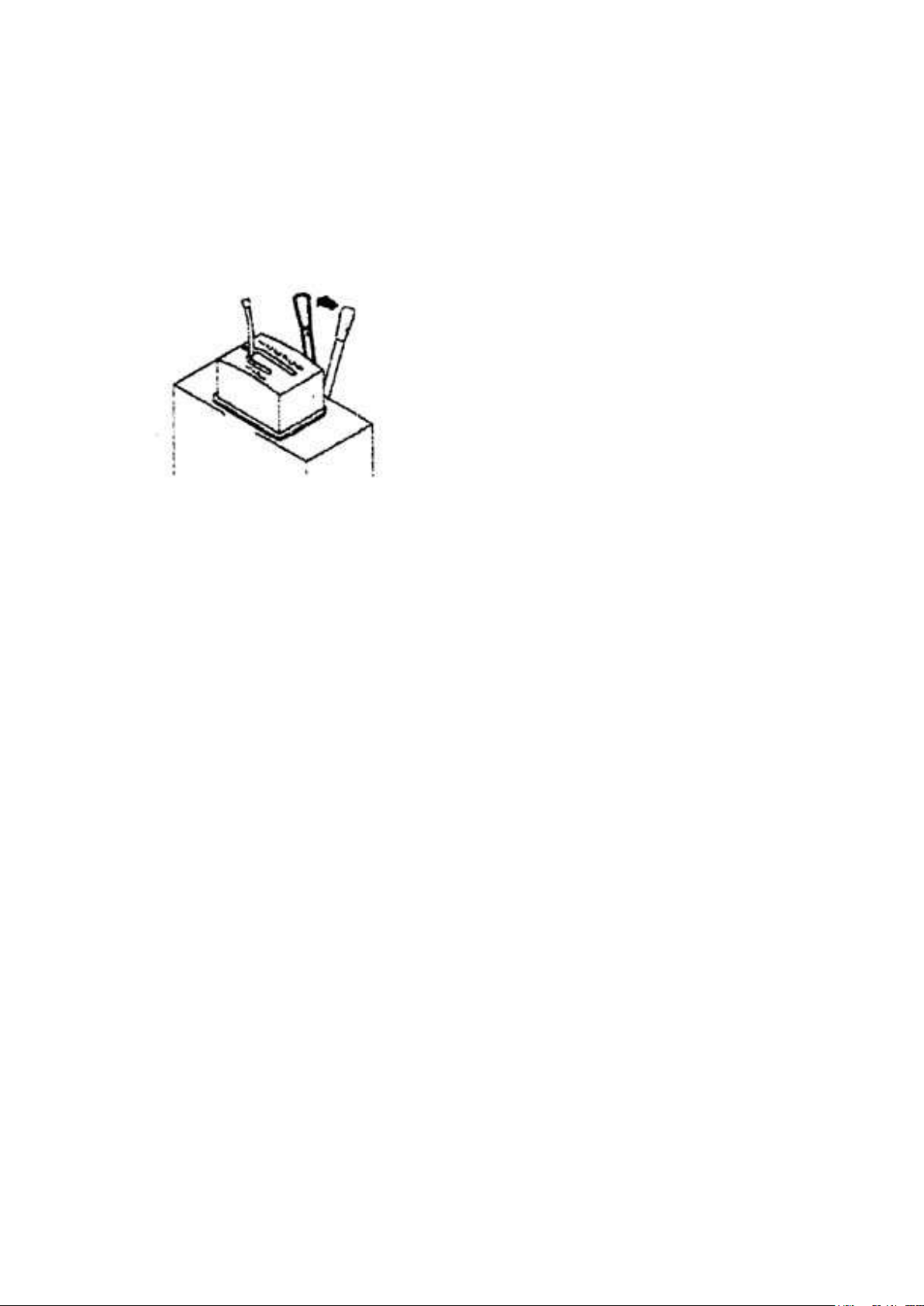
1. Pull fuel control lever (1) and run the
engine at medium speed for about 5
minutes with no load.
2. Run engine with light load until engine
water temperature gauge indicator move
into green range.
3. After warm-up run, check all gauges and
wiring lamps for proper operation.
4. Check for normal coloration of exhaust,
any abnormal sound or vibration.
Check After Starting:
After starting the engine, do not operate the machine immediately. First carry out the
following operations and checks.
★ Don’t run the engine at low idling or high idling for more than 20 minutes. If it’s
necessary to run the engine at idling, apply a load from time to time to raise the engine speed
to a midrange speed.
10- 19
Page 20
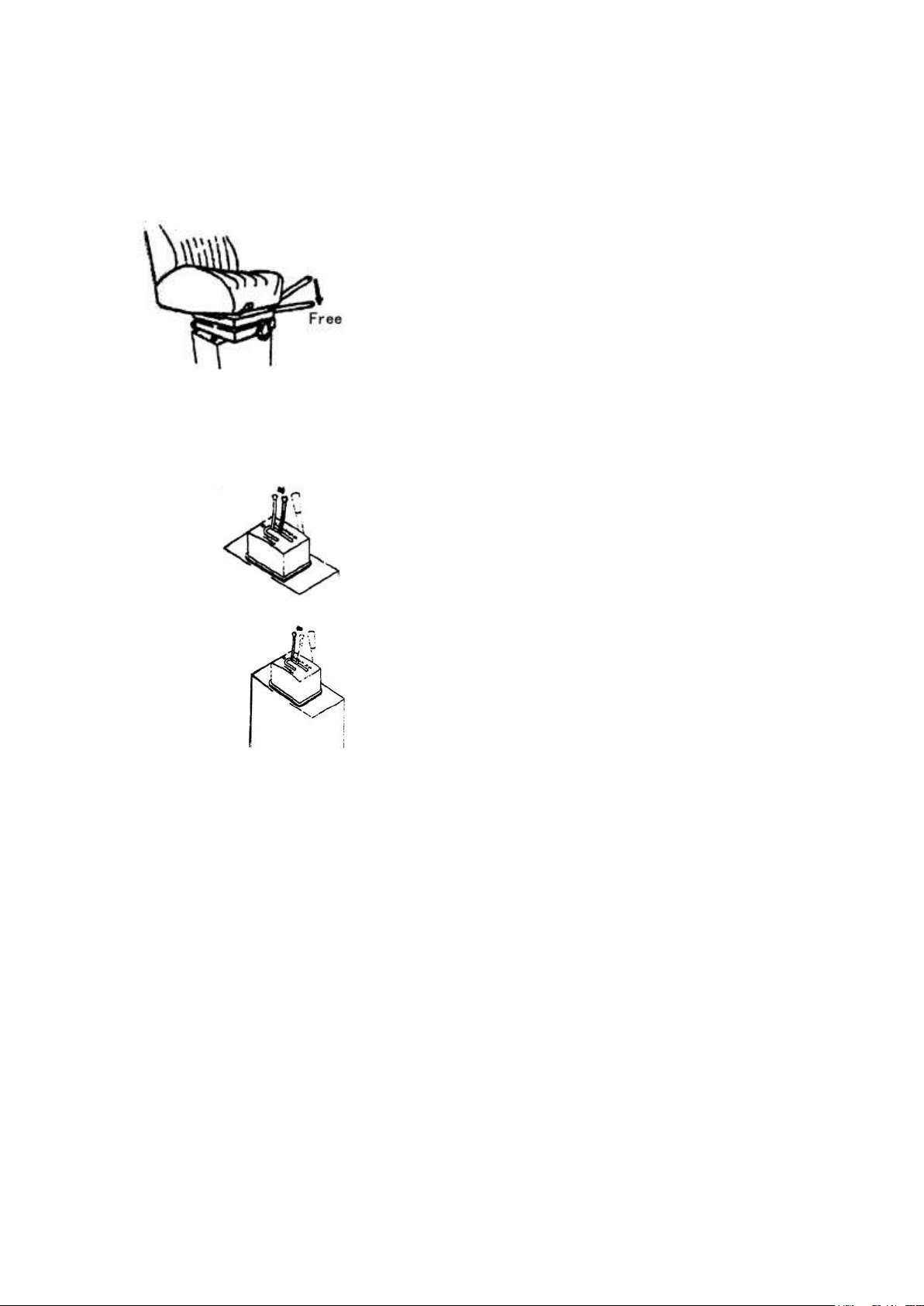
1. Set the gearshift lever to 1st speed.
★ When starting the machine, check that the
parking brake pilot lamp goes out.
★ Set the gear shift lever to 1st speed first,
then set it to higher speed by degrees.
3. Depress the accelerator pedal and the
machine will start.
1. Acceleration
Partially release the accelerator pedal and
shift gearshift lever to the next stepped up
position.
2. Deceleration
Release the accelerator pedal to reduce the
traveling speed and shift the gearshift lever to
the next stepped-down position.
★ When shifting gear, always shift one
speed at a time.
To Move the Machine off
1. Free parking brake lever and check that parking brake pilot lamp goes off.
Changing Gear Speed
10- 20
Page 21
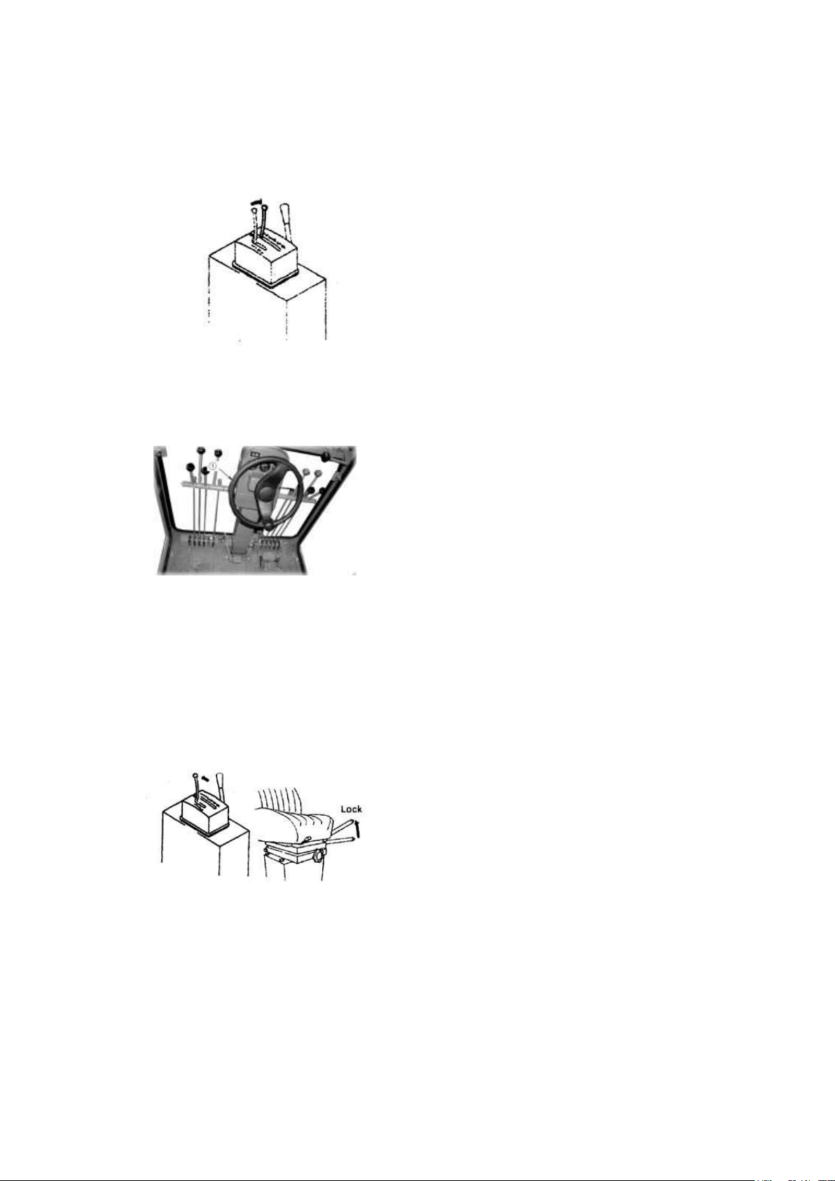
1. Depress the brake pedal to reduce the travel
speed and to stop the machine.
2. Set the gearshift lever to the desired position,
then depress the accelerator pedal slowly and
release the brake pedal to start the machine.
★ The engine running speed should be reduced
when shifting.
The grader turns to the desired side by turning the
steering wheel (1) to that side.
★Leaning to the turning side will minimize the
turning radius. In case the grader turns while
reversing, leaning to the opposite of the turning side
will minimize the turning radius.
1. Release accelerator pedal.
2. Depress brake pedal to stop the machine.
3. Set gearshift lever to neutral position, and
then pull the parking brake lever to apply
the parking brake.
Forward/Reverse Shifting
Always stop the machine when switching between FORWARD and REVERSE.
Turning
★In case the leaning was used for turning, return the steering wheel after the leaning was
returned to the desired position.
TO STOP THE MACHIMNE
10- 21
Page 22

CAUTIONS FOR OPERATING
·Drive the machine straight during uphill or downhill traveling. Specially, turning the
machine on the gravelly or clayey slant will cause the machine to slip easily.
·If the engine stops on the slant, depress the brake pedal immediately with full force, and at
the same time, pull the parking brake lever to stop the machine. Then place the gearshift lever
in N (neutral) and start the engine again.
▲ If the engine stops, the brake booster will not work, so the pedal will become heavier and
the braking effect will drop even if the brake is depressed with the same force.
·When tires get stuck while working in swamp or mud, travel with repeated articulation to
simplify getting out of the poor ground.
·This machine has two brake control systems. If one brakes down, the other is still effective.
However because braking capacity is reduced, drive slowly when traveling.
·Operating the articulation system when traveling at high speed may cause the machine to
overturn. Always perform this operation at a speed below 10 km/h. (with articulated)
WHEN TRAVELING DOWNHILL
When traveling downhill, use the same speed range as when traveling uphill, and make full
use of the engine to brake the machine.
If travel speed is still too fast, use the foot brake.
▲ Never shift gear or place the transmission in neutral when traveling on a slope. It is
dangerous to do this, as the engine cannot be used to brake the machine. Always place the
transmission in the appropriate speed range before starting to travel downhill.
▲ To prevent overrun, always shift down one gear at time. Allowing the engine to overrun
may cause damage to the engine or transmission.
10- 22
Page 23
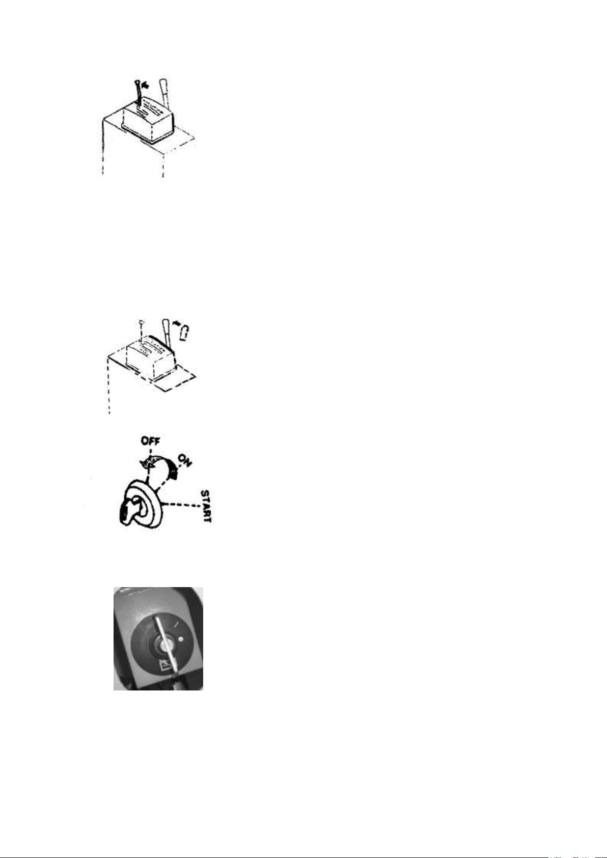
▲Stop the machine on hard and even ground to prevent it from
falling down or slipping.
▲ When the machine is to be left stopped for a while, leave the
engine in low idling or stop the engine. Apply the gearshift
lever lock and the parking brake.
▲ Emergency brake
▲ If an emergency stop has been made when the machine is
traveling, use the parking brake together with the wheel
brake.
When the emergency brake has been used, check the parking
brake lining, and then replace the lining.
TO STOP THE ENGINE
1. Idle the engine at low speed for about 5 minutes to cool it.
2. Set the fuel control lever to the STOP position to stop the
engine.
★ It is also possible to release the accelerator pedal to
STOP position and stop the engine.
3. Return the staring switch to the OFF position, and withdraw
the key.
★Do not attempt to stop a hot engine immediately unless it is
necessary. Such unreasonable operation will case remarkable
shortage of life of the various engine parts.
★Specially when stopping an overheated engine, be sure to cool
the engine gradually by idling it at a middle idling speed.
4. Set the chopper switch on OFF position.
10- 23
Page 24
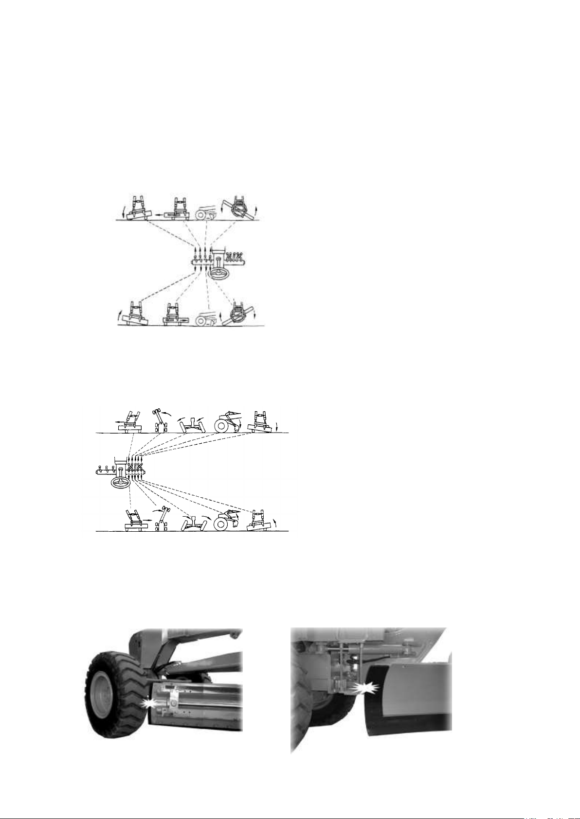
When operating the work equipment
control lever, sufficient attention is
required for the movement of the
work equipment and its movement
range must be limited, as the work
equipment or the hydraulic cylinder
possibly hit against parts, damaging
them.
OPERATION OF WORK EQUIPMENT
OPERATION METHOD OF THE WORK EQUIPMENT CONTROL LEVER
There are provided eight work equipment control levers, which are operated as are indicated
in the following figures.
Left-side Control Lever
Blade lifting Blade side shifting Power tilt Blade rotation
Right-side Control Lever
Drawbar side Articulation Leaning Scarifier Blade lifting
shifting (选购)
CAUTIONS IN OPERATION OF WORK EQUIPMENT
When the work equipment is operated, special attention should be given to contracts at the
following parts.
Front wheel and blade Blade and step
10- 24
Page 25
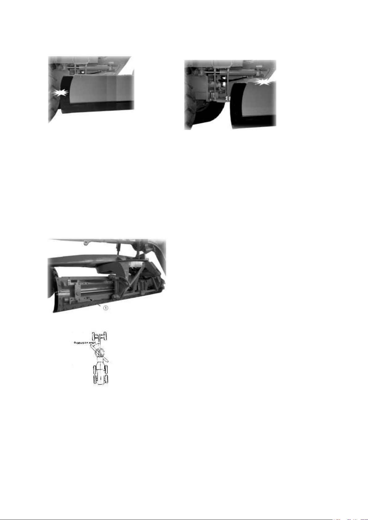
Position (1)
Angle of blade and body centerline is called
the blade propulsion angle. In the normal
scraping work, set the angle at 60°, more or
less. Set at a lesser angle when the scraping
resistance is great, or when the soil is hard, or
when the soil in front of the blade is difficult
to carry or throw to the side.
Rear wheel and blade Blade and frame
ADJUSTMENT IN SHIFTING OF WORK ATTACHMENT
It is essential to shift the work attachment to an optimum position for each work to allow high
job efficiency.
BLADE PROJECTION
The degree of projection is controllable by the control lever during operation. If further
projection is needed, stop the grader for a while and change the installing position of the blade
horizontal shifting cylinder piston rod, as follows.
·Projection to left
PROPULSION ANGLE OF BLADE
ADJUSTMENT OF BLADE CUTTING ANGLE
In hard soil cutting, it is advisable to lean the blade forward. As the soil becomes softer, lean
the blade more backward. This operation will improve job efficiency.
It is essential to adjust the cutting angle of blade, depending on the soil condition.
STANDARD BLADE CUTTING ANGLE (32°)
10- 25
Page 26
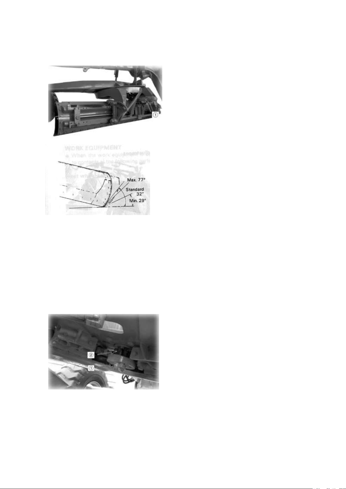
ADJUSTMENT
Standard cutting angle position can get by
operating power tilt control lever.
1. Turn the blade so as not to touch the
grader body and set the blade in the same
direction to the body.
2. Then,Operate power tilt control lever(1) .
A shear pin (1) is provided on the CIRCLE to
prevent the blade from unexpected failure,
because of abnormal impact load placed on
the blade edge during operation. If the shear
pin is broken during operation, remove bolt
(2) and lock plate and pull out the shear pin to
replace by new one.
SAFFLY DEVICE OF BLADE
During the operation of scraping, when the rotation is required, if encounter resistance,don’t force the rotation, please bring
the soil scraping plate and rotary, after the angle is adjusted, then re-process the operation of scroping.
10- 26
Page 27
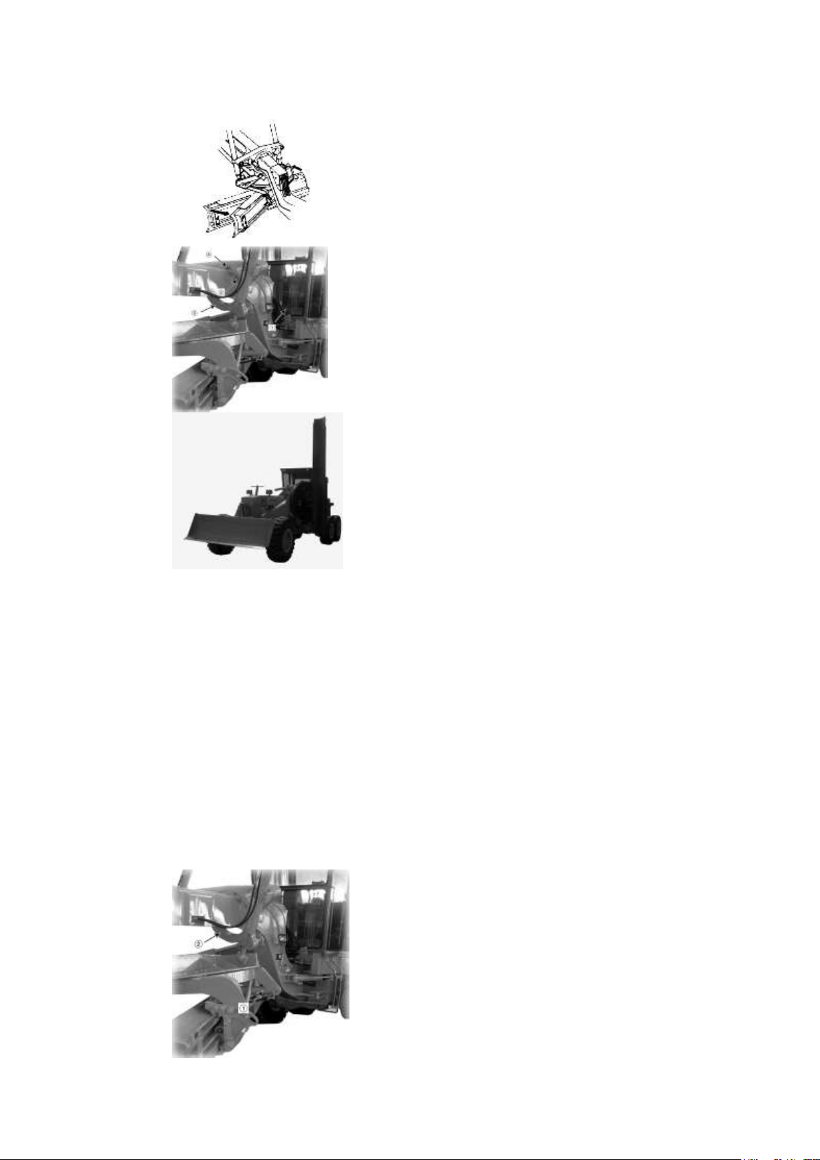
1) Fully protrude the blade and draw bar
to the right so that blade angle shown
in the figure can be obtained.
2) Depress lifter lock pin pedal (1) on
operator´ s compartment to remove
pin(2).
★If the blade cannot be removed because of
interference with lifter (3), operate the blade
lift cylinders as necessary.
3) Rotate lifter (3) by protruding the
right-hard blade lift cylinder piston
rod and retracting the left-hard blade
lift cylinder piston rod. When top
hole (A) in lifter approaches pin(2),
release lifter lock pin pedal(1) and
slowly rotate the lifter until pin(2)
enters hole(A).
4) Retract the right-hard lift cylinder
and protrude the left-hard cylinder.
Repeat this several times so that
circle is rotated with the blade raised
on the right-hard side, and desired
bank-cut posture can be attained.
1) Rotate lifter (1) in a similar manner to the
bank cutting posture, and lock it using
bank control lock pin (2).
2) Rotate the circle to the desired position.
★ Put the machine in the left hand side
shoulder reach posture using the same
procedure as the above.
BANK-CUTTING POSTURE (RIGHT SIDE)
★When bringing the blade into bank-cut posture, be careful not to clash the blade against
various portions of the machine.
★When bringing the blade into bank-cut posture on the left-side of the machine, change
every “left-hand” and “right-hand” in the above mentioned description with each other.
★Cutting edge of the blade may brake pavement if the blade is brought into bank-cut posture
on the roadway. Cover the pavement with iron plate at the portion with the blade cutting edge
may come into collision.
★Relocating the blade side-shift cylinder piston rod mounting position to the right (when
right-hand bank cutting is made) or to the left (when left-hand bank cutting is made) will
improve band cutting efficiency.(See side –shifting of the Blade)
▲ Do not attempt to depress the bank control lock pin removing pedal unless the blade is
rested on the ground. If the pin is removed with the blade raised off the ground, dangerous
falling of the blade with rotation of the circle may result.
SHOULDER REACH POSTURE (RIGHT SIDE)
10- 27
Page 28
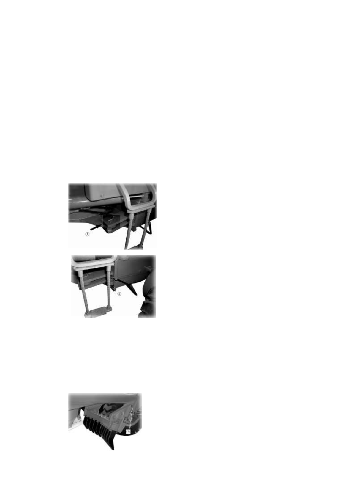
1.Take off lock line (1).
2.Set the lock line to the bracket (2) in the
rear.
★ Do not articulate the machine with
propulsion angle of the blade. Otherwise, the
blade may bend the step.
★When turning with the machine articulated,
pay particular attention to the clearance
between the blade end and the rear wheel.
Remove bolt (1) and select a bolt hole
adequate to the cutting angle. The cutting
angle is adjustable from 58ºto 68º (standard)
★When increasing the size of the shoulder reach, change the mounting position of the piston
rod of the blade horizontal feed cylinder. (Refer to the section on blade thrust)
★The banking performance is improved, if the mounting position for the piston rod of the
blade horizontal feed cylinder is changed as follows:
·When banking to right, to a position where the blade is thrust to right.
·When banking to left, to a position where the blade is thrust to left.
ARTICULATED OPERATIONS
When performing operations with the machine articulated, remove the lock line on the left
side of the machine.
The machine can be articulated 26º to both right and left, giving a minimum turning radius of
6.6 m.
▲For normal traveling operations, do not remove the lock link.
ADJUSTMENT OF SCARIFIER
a. ADJUSTMENT OF CUTTING ANGLE
As the soil becomes harder, a wider cutting angle increases job efficiency.
Adjustment
10- 28
Page 29
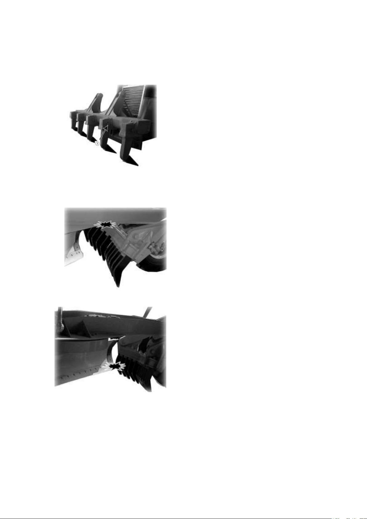
Remove the cotter pin, pull wedge (1) and
change the notch of tooth.
When the machine body is raised by using the
blade as a jack, while the scarifier is lifted to
the top position, the draw bar will come into
collision with the scarifier. This will cause
damage to the draw bar.
When turning the blade, with it several cm
off the ground, the blade may touch the
scarifier. This may damage the upper part of
the blade.
b. ADJUSTMENT OF CUTTING DEPTH
As the cutting depth is adjustable from tooth, adjust the tooth to job property.
Adjustment
PRECAUTIONS FOR SCARIFIER OPERATION
10- 29
Page 30
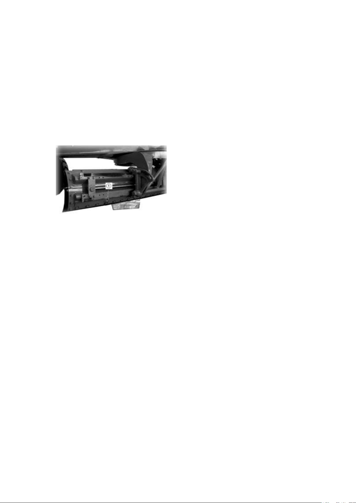
1. Lift the blade to a suitable height and put a
block underneath the blade rail to prevent its
falling.
▲Do not raise the blade unnecessarily high.
Be sure not to put your body underneath the
blade when blocking it.
2. Clean the mounting face after detaching
the cutting edge and the end bit.
3. Mount the cutting edge after inverting it, or
replacing it with a new one.
4. Mount the end bits after inverting and
switching right for left, or replacing with new
ones.
REVERSING AND REPLACEMENT OF CUTTING EDGE AND END BIT
Be sure to replace cutting edges and side edges before they wear down to a width of less than
10 mm from blade base.
When wear is extended to the mounting faces, their repair must be done prior to replacing.
TURNING AND REPLACTING
★Tightening torque for the mounting nuts :265±35N.m
★Tighten the nuts again after several hours' operation.
★If both ends of the cutting edge and side edges are worn out, replace them with new ones.
10- 30
Page 31
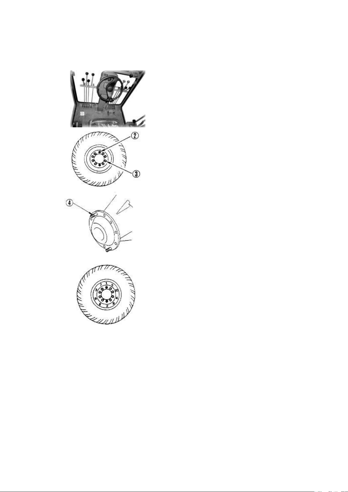
HOW TO CHANGE TIRES
1.Front wheel
1) Place the work attachment on a ground and
pull fully parking brake lever (1).
2) Then, attach the socket wrench (accessory
machine tool) to hub nuts (2) and bolts (3)
and loosen all the hub nuts and bolts by 3/4 to
1 turn.
3) Depress the lift cylinder. If the front tires
are lifted, remove hub nuts (2) and bolts (3)
and change all the tires.
4) When installing, align the tire with stud
(4), then install and tighten lightly with hub
nuts (2).
5) Tighten bolt (3) lightly, then raise the lift
cylinder, and lower the front tires to the
ground. Follow steps 1 to 10 to tighten to the
specified torque.
CHANGING TIRES
★Coat the threaded part with molybdenum disulphide grease before tightening.
★Tightening torque :450±50N.m
▲ Whenever the front tires are raised off the ground, support the front axle center frame on
the stand to assure safety.
2. Rear wheel
1) Repeat the front wheel change procedures 1) and 2).
2) Depress fully the right and left lift cylinder and the front tires are lifted about 50cm off
ground. Retract the lift cylinder on the side where the tire is not removed, to lift the rear
wheels.
3) Install new tires according to the procedure 4) of the front wheel tire change.
10- 31
Page 32

★Coat the threaded part with molybdenum disulphide grease before tightening.
★Tightening torque :450±50N.m
▲Whenever the rear wheel are raised off the ground, stably support the tandem on the block
to assure safety.
▲When a front tire punctures, do not attempt to travel the machine by temporarily applying a
pad to the swing stopper. If it is necessary, travel the machine slowly only within the
minimum necessary distance.
In the case, be sure to securely keep the punctured tire off the ground with chains, etc.
HOW TO USE LEANING STOPPER
When the leaning pipe is damaged, temporarily prevent the front wheels from leaning so that
the machine can be successfully self-propelled to the nearest repair shop.
HOW TO APPLY THE LEANING STOPPER
Fix the leaning rod to the front axle using the bolt provided in the toolbox.
▲ If the machine is traveled with the leaning cylinder piston rod fluctuating or the front
wheels leaning on one side, because of damaged leaning piping, dangerously unstable
steering and excessively worn tire will result. Have the faulty leaning pipe repaired by
mechanics quickly.
10- 32
Page 33
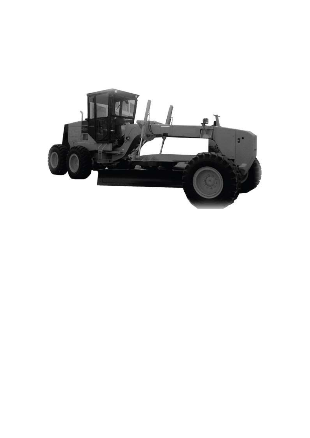
When traveling, set the blade at the minimum propulsion angle and raise the blade fully.
DRIVING ALONG ROAD
In addition to strict observance of traffic laws and regulations concerned, keep the
following in mind:
POSITION OF BLADE WHEN TRAVELING
PRECAUTIONS WHEN TRAVELING ON ROAD
To relieve operator's fatigue, take a rest by 30 minutes to 1 hour and 30 minutes mode, every
80 kilometers or every 2 hours of traveling.
10- 33
Page 34

TOWING
TOWING THE MACHINE
This machine must not be towed except in emergencies. When towing the machine, take the
following precautions.
When engine can be used
·Always keep the engine running when towing the machine, so that the steering and braking
can be used.
When engine cannot be used
·When transporting a disabled machine by towing, the transportation distance should be
within 600m at a speed of 8km/h or less. (When towing more than 600m, remove the drive
shaft.)
★If the distance is more than the above mentioned, or it more than one day has elapsed since
the engine trouble, be sure to use the trailer for transportation.
★If the machine is towed without the engine running, no lubrication oil will be supplied to
the transmission. The gears and bearing are rotated, so this may cause them to be damaged.
★When the engine cannot be used or the steering booster cannot be used, operation of
steering wheel is difficult, so run the machine slowly.
10- 34
Page 35

COLD WEATHER OPERATION
PREPARATION FOR LOW TEMPERATURE
If the temperature becomes low, it becomes difficult to start the engine, and the coolant may
freeze, so do as follows:
FUEL AND LUBRICANTS
Change the fuel and oil with low viscosity for all components.
For details of the specified viscosity, see the TABLE OF FUEL, COOLANT AND
LUBRICANTS.
COOLANT
After cleaning inside of the cooling system, add antifreeze to the coolant to prevent the
coolant from freezing when the machine is not being used.
★For details of the antifreeze mixture when changing the coolant, see WHEN REQUIRED.
CARE IN USING ANTIFREEZE
Use a Permanent Antifreeze (ethylene glycol mixed with corrosion inhibitor, antifoam agent,
etc.) meeting the standard requirements as shown below. With permanent antifreeze, no
change of coolant is required for a year. If it is doubtful that an available antifreeze meets the
standard requirements, ask the supplier of that antifreeze for information.
STANDARD REQUIREMENT FOR PERMANENT ANTIFREEZE:
<TECHNICAL SPECIFICATION SAFETY USED FOR VEHICALE ENGINE
COOLANT> ……JT 225-1996
★Never use methanol, ethanol or propanol based antifreeze.
★Where no permanent antifreeze is available, an ethylene glycol antifreeze without corrosion
inhibitor may be used only for the cold season. In this case, clean the cooling system twice a
year (in spring and autumn). When refilling the cooling system, add antifreeze in autumn, but
do not add any in spring.
★Absolutely avoid using any water leak preventing agent irrespective of whether it is used
do independently or mixed with an antifreeze.
★Do not mix one antifreeze with a different brand.
▲Antifreeze is flammable, so keep it away from any flame.
BATTERY
As ambient temperature drops, battery capacity will drop, and electrolyte may sometimes
freeze if battery charge is low. Maintain battery at a charge lever of approx.100% and insulate
it against cold temperature so that machine can be readily started the next morning.
★Measure specific gravity of fluid and rate of charge from the following conversion table.
10- 35
Page 36

Tem.of fluid
Rate of charge
20℃
0℃
-10℃
-20℃
100%
1.28
1.29
1.30
1.31
90%
1.26
1.27
1.28
1.29
80%
1.24
1.25
1.26
1.27
75%
1.23
1.24
1.25
1.26
★When electrolyte lever is low, add distilled water in the morning before work instead of
after the day´s work. This is to prevent fluid from freezing at night.
▲To avoid gas explosions, do not bring fire or sparks near the battery.
▲If the electrolyte gets on your skin or clothes, immediately wash with plenty of clean water.
10- 36
Page 37

MEMO
10- 37
Page 38

PERIODIC MAINTENANCE
Proper lubrication and maintenance assure trouble free operation and long machine life. Time
and money spend for scheduled periodic maintenance will be amply compensated by
prolonged machine operation and reduced operating coast.
All hourly figures giving in the following descriptions are based on service meter readings. In
practice, however, it is recommended to rearrange all of them into units of days, weeks and
months to make the maintenance schedule more convenient. Under rough job site or operating
conditions, it is necessary to somewhat shorten the maintenance intervals stated in this
manual.
10- 38
Page 39

No
ITEM
SERVICE
PAGE
CHECK BEFORE STARTING
a Oil and water leak
Check
10-12 b Nuts and bolts
Check and retighten
10-12
c
Coolant
Check and refill
10-12
d
Engine oil pan
Check and supply
10-12
e
Fuel
Check and refill
10-13
f
Fuel tank
Drain water and sediment
10-13 g Dust indicator
Check
10-13 h Steering wheel
Check and adjust
10-14 i Braking ability
Check and adjust
10-14
j
Parking brake lever travel
Check and adjust
10-14 k Tire pressure
Check and adjust
10-14
l
Lamp
Check
10-15
m
Rear view mirror
Check
10-15
n
Horn
Check
10-15
MAINTENANCE TABLE
10- 39
Page 40

No
ITEM
SERVICE
PAGE
o
Exhaust gas color
Check
10-15 p Instrument
Check
10-15
q
Previous day´s defects
Check
10-15 r Door lock
Check
10-15
s
Wiper
Check
10-15
t
Electric wiring
Check and retighten
10-15
EVERY 50 HOURS SERVICE
a
Lubricating
10-46
-1
Circle
Lubricate
10-46
-2
Blade guide rail
Lubricate
10-46
EVERY 100 HOURS SERVICE
(This item is carried out after the first 100 hours only for new
machines.)
Filter for transmission case
Change oil, replace element
10-46
10- 40
Page 41

No
ITEM
SERVICE
PAGE
EVERY 250 HOURS SERVICE
(The item marked ★ are carried out after the first 250 hours
only for new machines)
★
Fuel filter
Replace cartridge
10-47
★
Engine oil pan and filter
Change oil and replace
cartridge
10-47
★
Final drive case
Change oil
10-47
★
Circle reverse case
Change oil
10-47 ★ Tandem drive case
Change oil
10-47
★
Hydraulic tank and filter
Change oil and replace
element
10-47
★
Engine valve clearance
Check and adjust
10-47
a
Lubricating
10-47
-1
Leaning cylinder pin
Lubricate 2 points
10-47
-2
Leaning rod end
Lubricate 2 points
10-47
-3
Steering rod
Lubricate 2 points
10-47
-4
Knuckle bracket king pin
Lubricate 4 points
10-48
10- 41
Page 42

No.
ITEM
SERVICE
PAGE
-5
Steering linkage
Lubricate 2 points
10-48
-6
Draw bar ball joint
Lubricate 1 points
10-48
-7
Front axle center pin
Lubricate 2 points
10-48
-8
Scarifier ball joint(optional)
Lubricate 4 points
10-49
-9
Scarifier cylinder pin(optional)
Lubricate 2 points
10-49
-10
Scarifier shaft(optional)
Lubricate 2 points
10-49
-11
Blade cylinder yoke
Lubricate 6 points
10-49
-12
Blade lift cylinder ball joint
Lubricate 2 points
10-49
-13
Draw bar side shift cylinder
ball joint
Lubricate 2 points
10-50
-14
Bank control guide
Lubricate 3 points
10-50
-15
Bank control lock pin
Lubricate
10-50
-16
Articulation center pin
Lubricate 2 points
10-50
-17
Articulation lock pin
Lubricate
10-50
-18
Articulation cylinder pin
Lubricate 4 points
10-50 b Transmission case
Check and supply
10-51 c Final drive case
Check and supply
10-51 d Tandem drive case
Check and supply
10-52
10- 42
Page 43

EVERY 250 HOURS SERVICE
e Circle reverse gear case
Check and supply
10-52
f
Hydraulic oil tank
Check and supply
10-52
g
Fan belt
Check and adjust
10-53
h
Fuel filter
Drain water and sediment
10-54
i
Parking brake lever travel
Check
10-54 j Battery electrolyte level
Check
10-55
k
Ball joint
Check and clearance
10-55 l Wheel hub nut
Check and retighten
10-55 m Wheel brake
Check and adjust
10-56
EVERY 500 HOURS SERVICE
a
Fuel filter
Replace cartridge
10-57
b
Engine oil pan and filter
Change oil and replace
cartridge
10-58
c
Transmission filter
Replace element
10-58 d Circle guide
Check clearance
10-59
10- 43
Page 44

No.
ITEM
SERVICE
PAGE
EVERY 1000 HOURS SERVICE
a
Lubricating
10-60
Drive shaft
Lubricate 2 points
10-60 b Transmission case
Change oil and replace element
10-60
c
Final drive case
Change oil
10-61
d
Circle reverse case
Change oil
10-62
e
Tandem drive case
Change oil
10-62
f
Hydraulic tank and filter
Change oil
10-63
g
Draw bar front ball joint
Check looseness
10-64
h
Toe –in
Check and adjust
10-64
i
Front wheel bearing play
Check and adjust
10-65
Turbocharger rotor
Check play
Refer to
the
engine
manual
Turbocharger various fasteners
Check and retighten
Corrosion resistor
Replace cartridge
10- 44
Page 45

No.
ITEM
SERVICE
PAGE
EVERY 2000 HOURS SERVICE
a
Front wheel bearing
Lubricate (both right and left
sides)
10-66
b
Engine breather
Clean
10-66
c
Turbocharger
Check and clean
10-67 d Alternator, starting motor
Check
10-67
e
Engine valve clearance
Check and adjust
10-67
f
Vibration damper
Check
10-67
EVERY 4000 HOURS SERVICE
a
Water pump
Check
10-68
WHEN REQUIRED
a
Cooling system
Clean
10-69
b
Air cleaner
Check, clean or replace
10-71
10- 45
Page 46
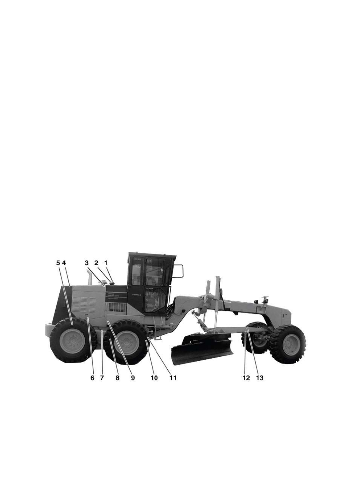
Oil Fillers and Location of Oil Meters
1. Hydraulic tank oil filler
2. Fuel tank lever gauge and oil
3. Hydraulic tank lever gauge
4. Cooling water inlet
5. Final drive case oil filler
6. Engine oil pan oil filler and lever gauge
7. Tandem drive case oil filler plug
8. Transmission case drain plug
9. Transmission case oil filler and lever gauge
10. Tandem drive case drain plug filler
11. Tandem drive case lever gauge
12. Circle reverse gear case drain
13. Circle reverse gear case oil filler
10- 46
Page 47
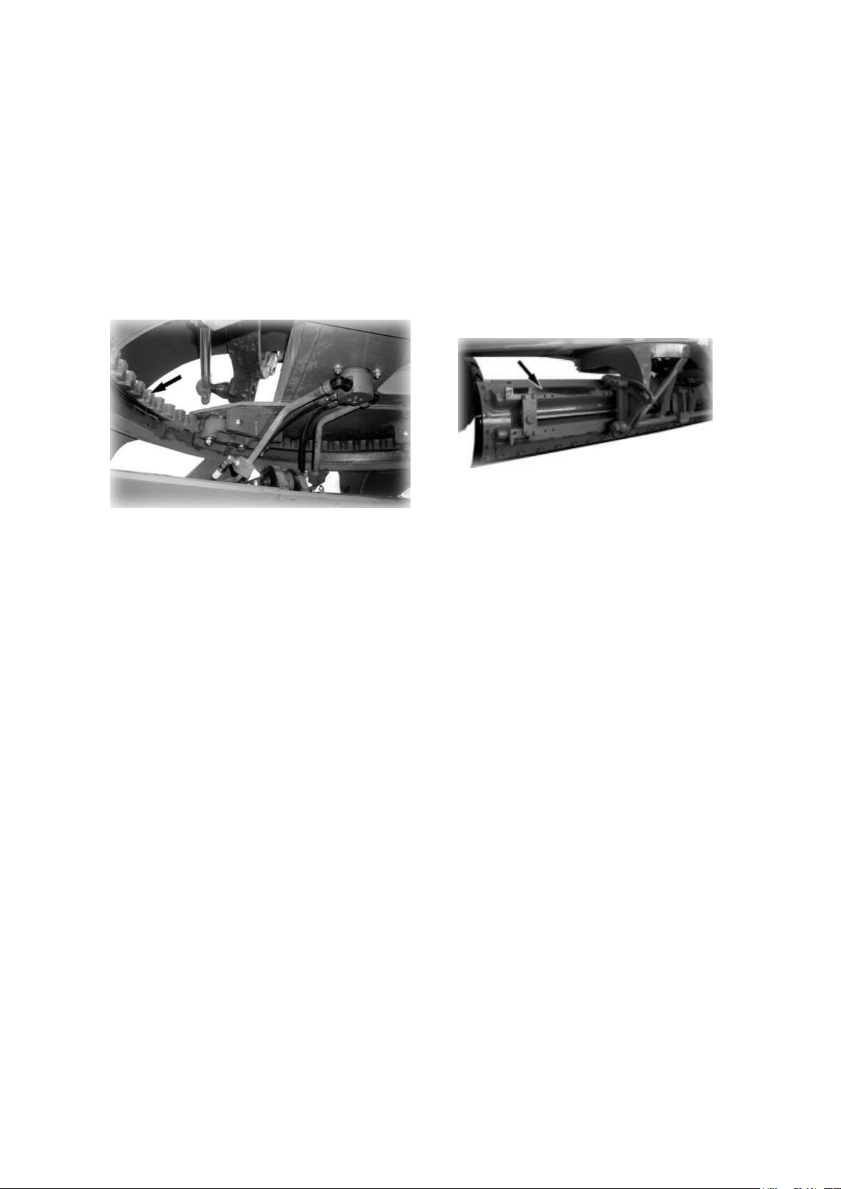
EVERY 50 HOURS SERVICE
a. LUBRICATING
APPLY GREASE TO THE GREASE FITTINGS SHOWN BY ARROWS.
1. Circle 2.Blade guide rail
Apply grease all around the circle part. Apply grease all over the guide rail.
EVERY 100 HOURS SERVICE
Carry out the following maintenance only after the first 100 hours.
·Change the transmission oil and replace the filter.
For details of the method of replacing or maintaining, see the section on EVERY 500
HOURS, 1000 HOURS and 2000 HOURS SERVICE.
10- 47
Page 48
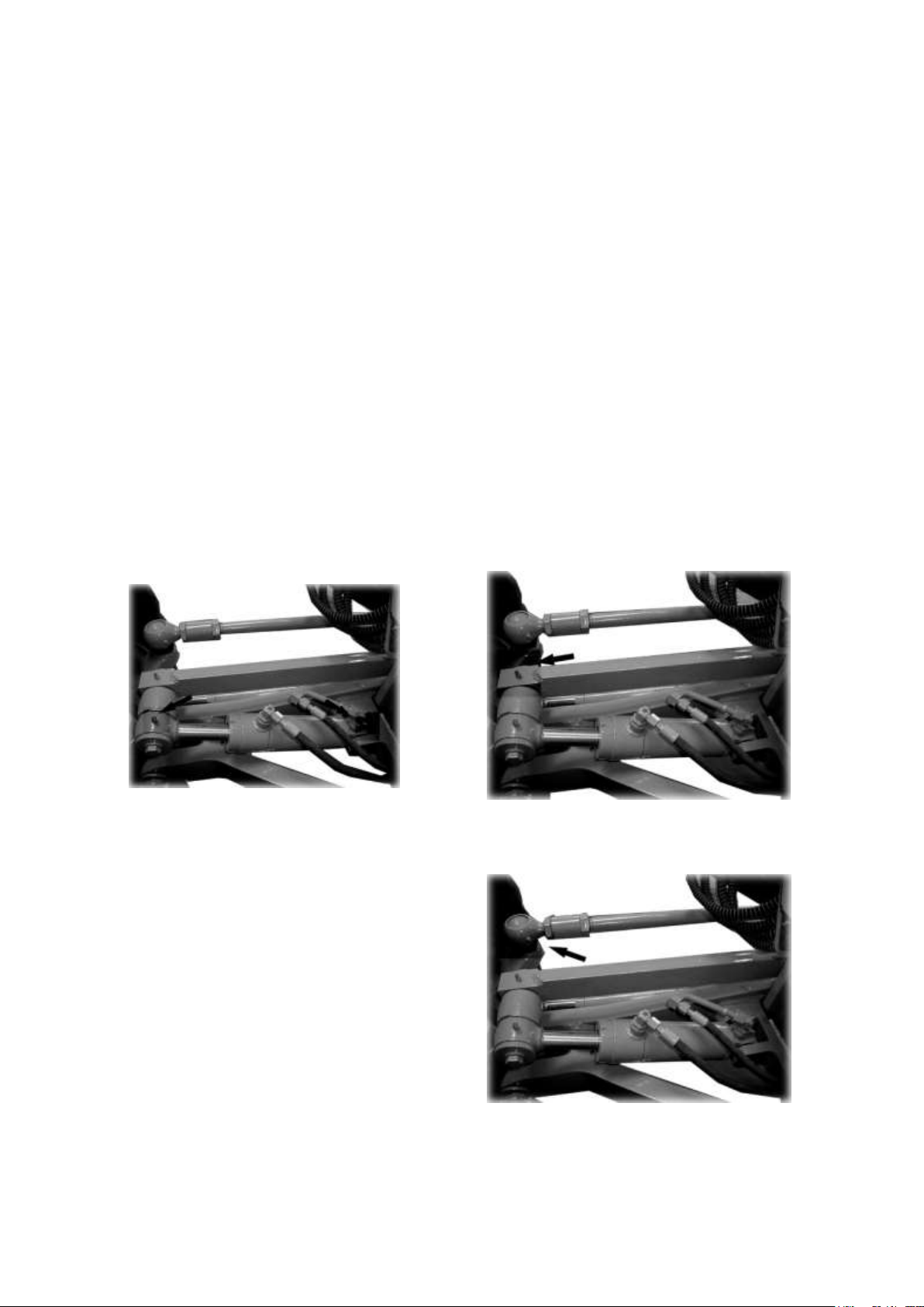
EVERY 250 HOURS SERVICE
★Maintenance for every 50 hours should be carried out at the same time.
Carry out the following maintenance only after the first 250 hours.
·Replace the cartridge of fuel filler.
·Change the oil in engine oil pan and replace the cartridge of oil filler.
·Change the oil of final drive case.
·Change the oil of circle reverse gear case.
·Change the oil of tandem drive case
·Change the oil in hydraulic tank and replace the element of filler.
·Check and adjust the engine valve clearance.
For details of the method of replacing or maintaining, see the section on EVERY 500Hours,
1000Hours and 2000Hours SERVICE.
a. LUBRICATING
Apply grease to the grease fittings shown by arrows.
1. Leaning cylinder pin (2 points) 2.Leaning rod end (2 points)
3.Steering rod (2 points)
10- 48
Page 49
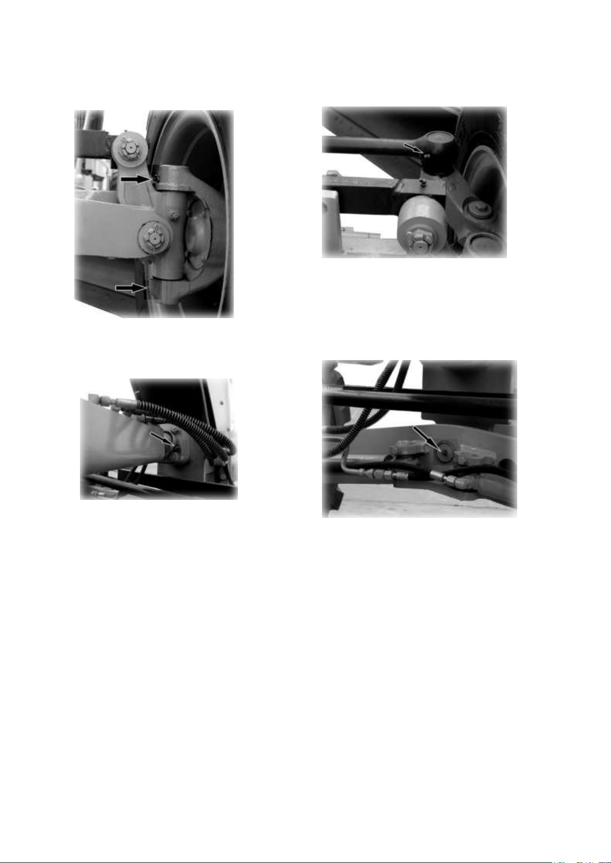
6.Drawbar ball joint (1 points)
7.Front axle center pin (2 points)
4. Knuckle bracket king pin (4 points) 5.Steering linkage (2 points)
10- 49
Page 50
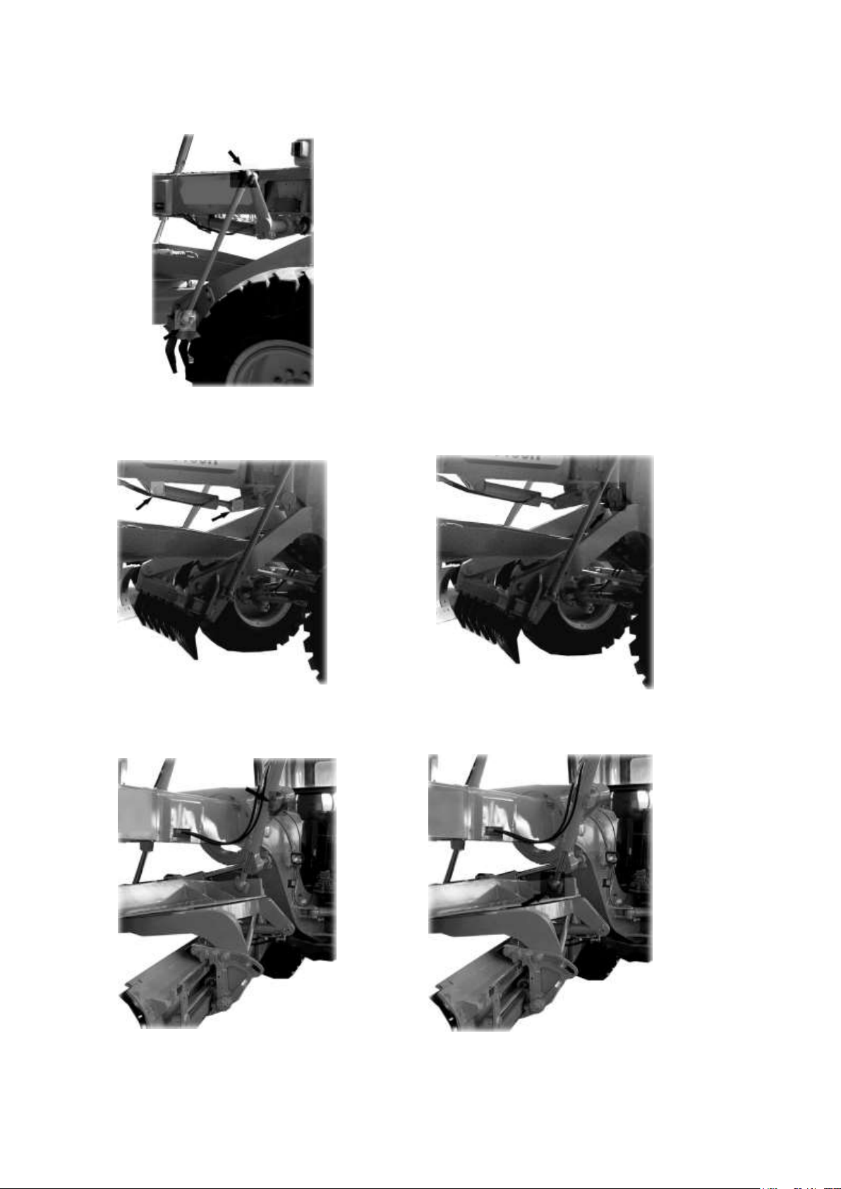
8. Scarifier ball joint (4 points)
9. Scarifier cylinder pin (2 points) 10.Scarifier shaft (2 points)
11. Blade lift cylinder yoke (6 points) 12. Blade lift cylinder ball joint (2 points)
10- 50
Page 51
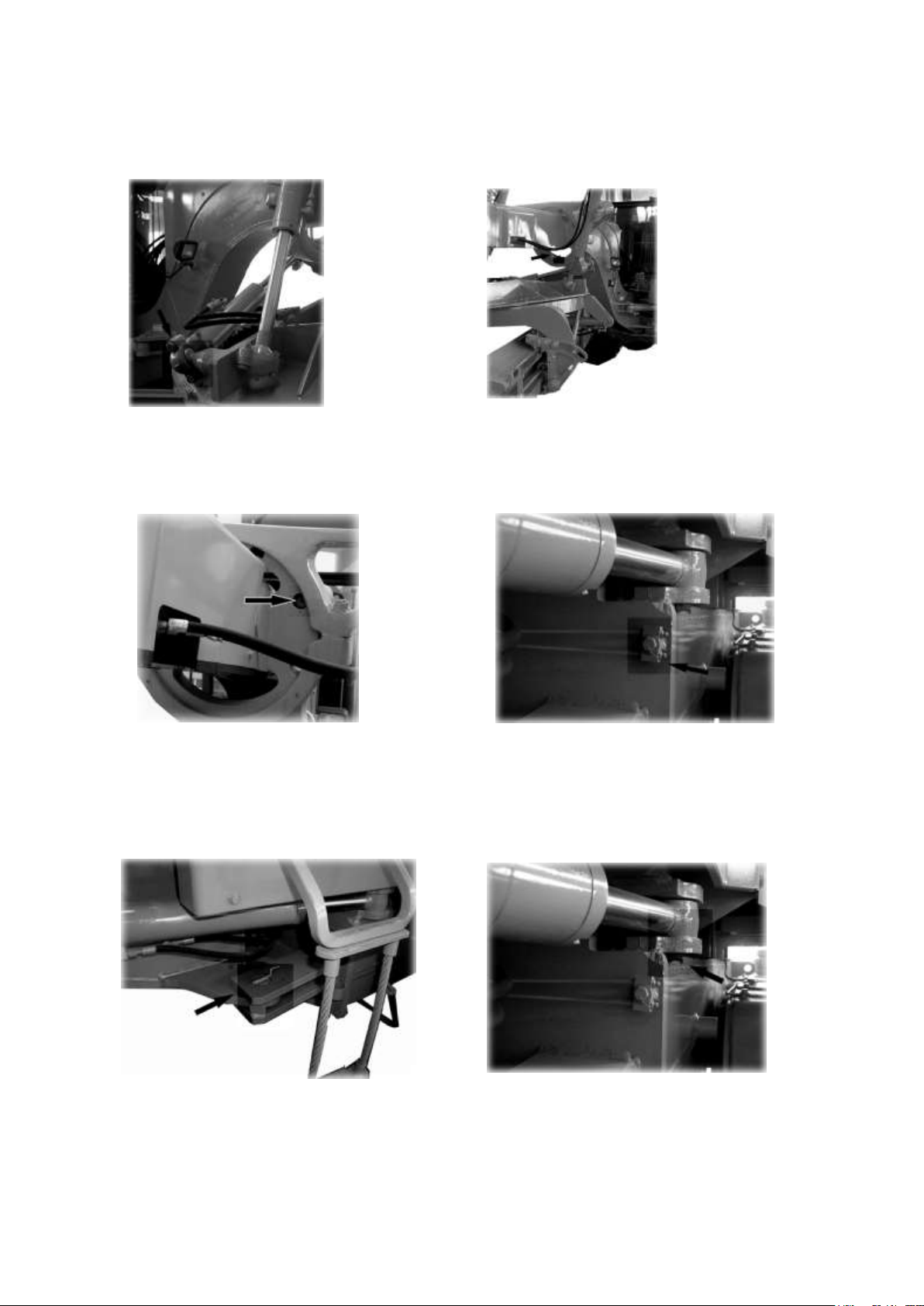
13. Draw bar side shift cylinder ball joint 14.Bank control guide (3 points)
(2 points)
15. Bank control lock pin (apply grease) 16. Articulation center pin (2 points)
17. Articulation lock pin (apply grease) 18. Articulation cylinder pin (4 points)
10- 51
Page 52
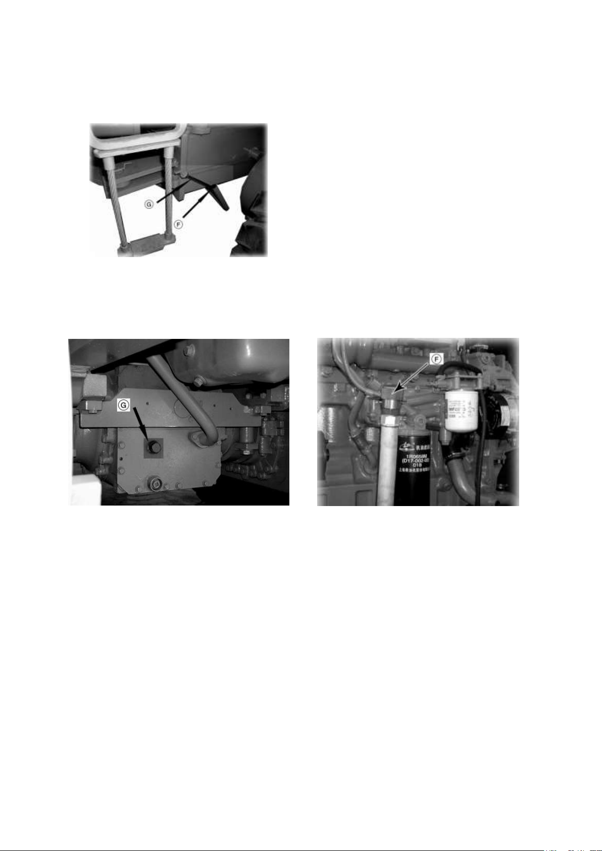
Check the oil lever with oil lever gauge (G).
If necessary, add oil through filler (F).
★Make an oil lever check 5 minutes after the
engine is stopped.
★The type of lubricant used depends on the
ambient temperature. Select according to the
table FUEL, COOLANT AND
LUBRICANTS.
b. TRANSMISSION CASE
c. FINAL DRIVE CASE
Check the oil lever with oil lever plug (G) 3minutes after stopped the engine. If necessary, add
oil through filler (F).
★The type of lubricant used depends on the ambient temperature. Select according to the
table “FUEL, COOLANT AND LUBRICANTS.”
10- 52
Page 53
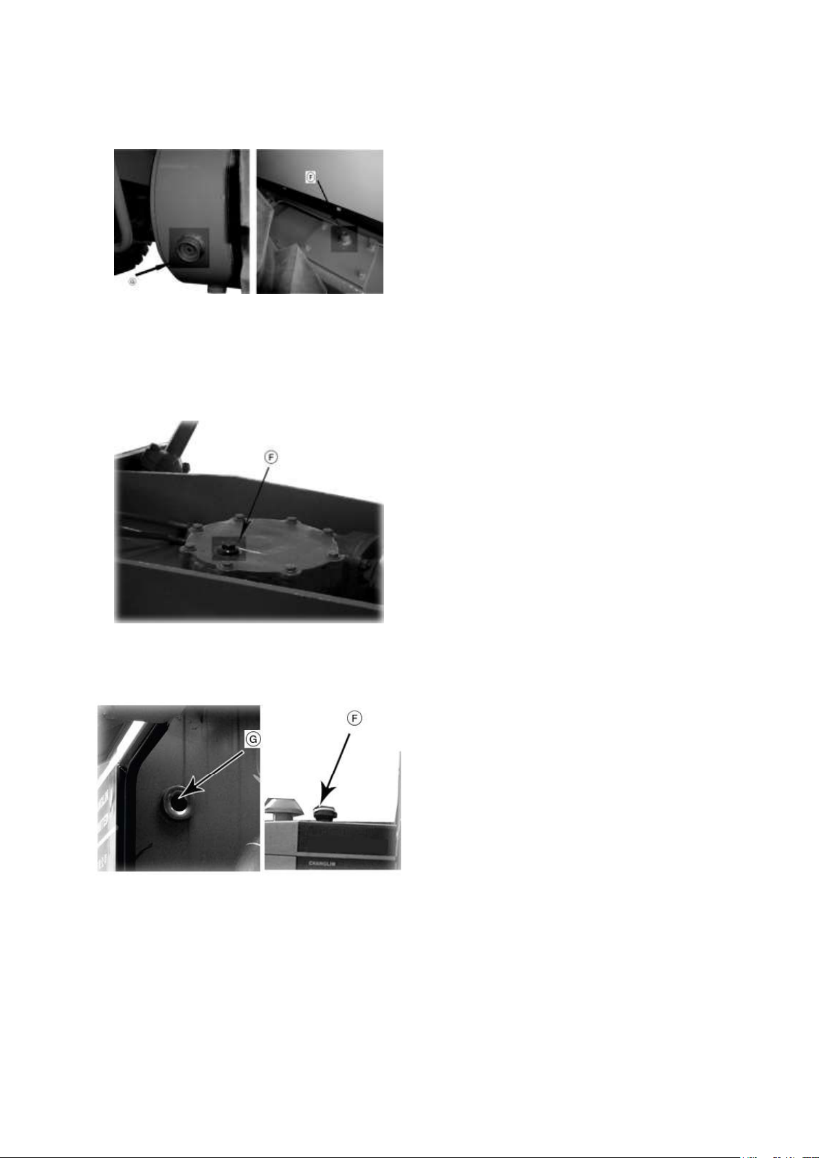
d. TANDEM DRIVE CASE
Check the oil lever with lever plug (G). If
necessary, add oil through filler (f).
★ The type of lubricant used depends
on the ambient temperature. Select
according to the table FUEL,
COOLANT AND LUBRICANTS.
Remove plug (F). Check if the oil lever is at
the gear upper face. Add the gear oil through
filler (F), if necessary.
★ The type of lubricant used depends on
the ambient temperature. Select
according to the table FUEL,
COOLANTAND LUBRICANTS.
1. Set the machine in position as follows to
check the oil lever.
·Return the leaning of the front tires to the
upright position and face the wheels straight
to the front.
·Set the front frame and rear frame facing
straight (articulated angle).
e. CIRCLE REVERSE GEAR CASE
f. HYDRAULIC OIL TANK
·Return the draw bar side-shift and blade side-shift to the center of the machine, set the blade
at right angles to the chassis and lower it lightly to the ground.
·Raise the scarifier fully.
2. Check the oil lever with sight gauge (G). Add hydraulic oil through filler (F), if necessary.
★When removing the filler cap to add oil, confirm that oil in the tank is cold (at about the
same temperature as the ambient air). The hydraulic tank is sealed, so if the filler cap is
10- 53
Page 54
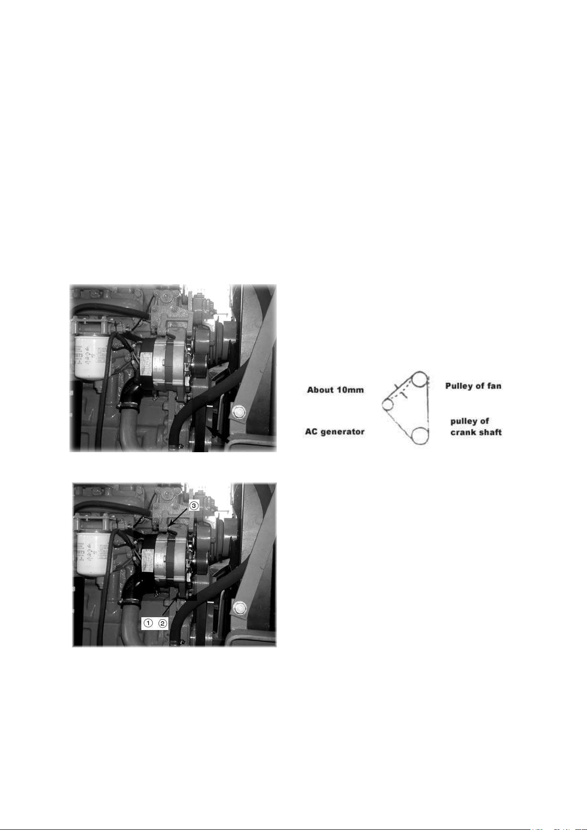
1. The belt tension should normally deflect by
about 10mm when pressed with the finger at a
point midway between the alternator pulley and
the fan pulley (approx. 6kg).
2. To adjust the belt tension, loosen bolt (1) and
nut (2) and shift alternator (3) slightly.
3. After adjustment, tighten bolt (1) and nut (2)
securely.
★When adjusting the V-belt, do not attempt to push
alternator (3) directly with a bar or the like, but use
a wood pad to prevent damage to the core.
removed when oil is hot and the filler cap is tightened, the oil temperature will drop by the
following morning. As a result, the pressure inside the tank to drop, and this will cause a drop
in the durability of the pump.
★When working at high altitudes or in cold weather, loosen the hydraulic tank cap to release
the pressure inside the tank before starting work (when the oil is cold).
★The type of lubricant used depends on the ambient temperature. Select according to the
table FUEL, COOLANT AND LUBRICANTS.
▲When oil temperature is high, do not move cap. Hot oil sometimes shouts out.
When removing the cap, turn it slowly to relieve inner pressure.
g. FAN BELT
★Check each pulley for damage, and V-grooves and V-belt for wear. Particularly, check
whether V-belt is in contact with bottom of V-groove through wear.
★Replace belt if it has stretched, leaving no allowance for adjustment, or if there is a cut or
crack on belt.
10- 54
Page 55
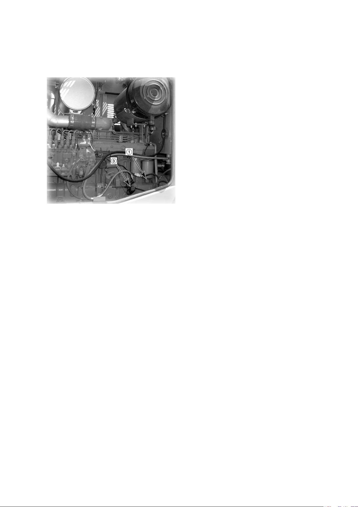
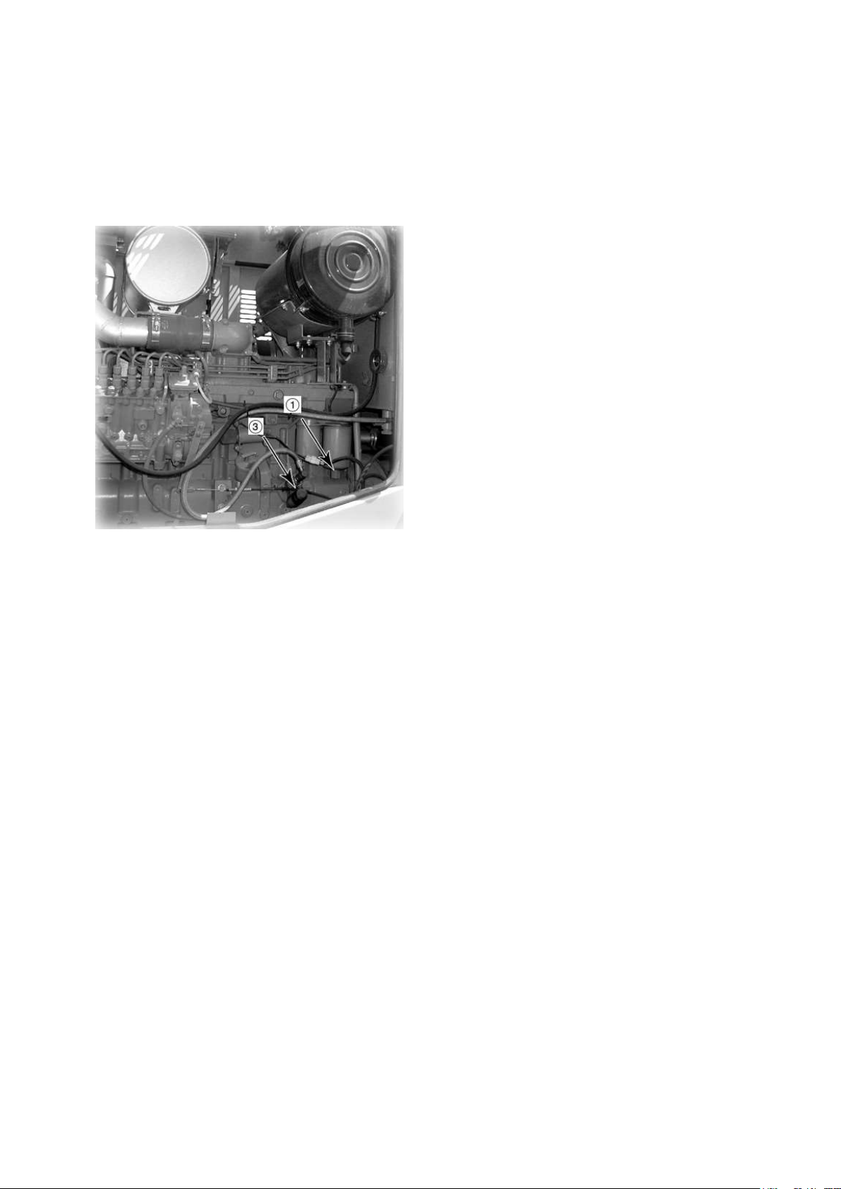
1. Remove drain plug (1) on the bottom of
the filter to drain water and sediment
accumulated on the bottom. After
draining, tighten drain plug (1).
2. Loosen air vent plug.
3. Loosen feed pump knob (3) and move the
pump up and down to draw off fuel until
air ceases to come out of plug.
4. Tighten air vent plug, push feed pump
knob (3) into place, and tighten it.
h. FUEL FILTER
i. PARKING BRAKE LEVER TRAVEL
If the normal braking grip is effective by pulling the brake lever 2 to 3 ratchets from the brake
release position, the brake lever travel is considered normal.
If six or more ratchets are counted before the parking brake comes into effect, the parking
brake flexible shaft should be adjusted until proper lever travel can be obtained.
10- 55
Page 56
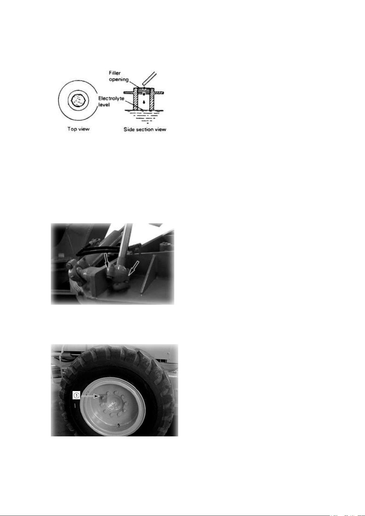
If the electrolyte level is below the prescribed
level of 10 to 12mm above the plate, add
distilled water. Should any of the acid be
spilt, have it replenished by the nearest
battery shop with acid of the correct specific
gravity.
Remove all shims. Tighten the cap in such a
manner that the clearances (shown in the
picture) on both sides are the same. Measure
the clearance with a thickness gauge, and
place the shims which are thicker than the
measured clearance by one shim. Then,
retighten the cap. One shim is equal to 0.2mm
thickness.
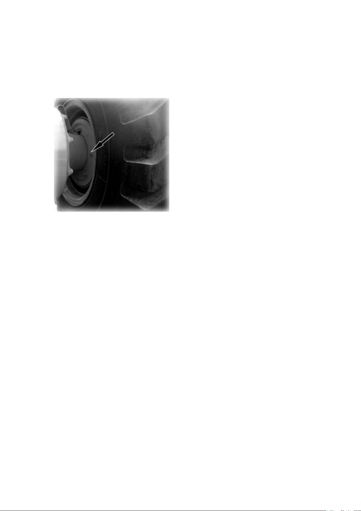
Loose wheel hub nuts and bolts (1) will result
in shortened life of tires or troubles. Carefully
check loosening of the nuts.
★Tightening torque :450±50N.m
★Check all the nuts and bolts for loosening.
Also, check the rim for damage. If a hub bolt
is broken, replace the total unit of the wheel
stud.
j. BATTERY ELECTROLYTE LEVER
★Clean the air hole of battery cap along with the level check.
★Never use metal funnel for electrolyte supply.
▲To avoid gas explosions, do not bring fire or sparks near the battery.
▲If the electrolyte gets on your skin or clothes, immediately wash with plenty of water.
k. BALL JOINT
★Repeat this procedure for each ball joint in the work equipment linkage.
l. WHEEL HUB NUT
★When checking for loose nuts, always turn the nut in the tightening direction to check.
★Coat the threaded part with molybdenum disulphide grease before tightening.
10- 56
Page 57
m. WHEEL BRAKE
ADJUST
1. Turn the adjusting gear, with the
screwdriver inserted into the hole on the
lower side of back plate, until the brake
lining comes into close contact with the
brake drum.
2. Back the adjusting gear 4 to 5 clicks.
3. Fit a 0.6mm gauge in one side of the
inspection window on the left or right and
check that the clearance on the other side
is less than 0.4mm.
4. After adjusting, check that the travel brake pedal is within 80mm.
★If deterioration of braking efficiency is suspected, check it as follows :
1) While the machine travels at about 20km/h of traveling speed, try lightly braking the
machine (so as not to cause wheel locking) three times.
2) Touch each brake drum by hand to see whether heating of drums is felt or not.
3) Cold drum, if any, may be assumed ineffective.
★Brake lining with block surface due to burning or lining soiled with oil causes insufficient
braking effect. Polish such a lining with sandpaper.
10- 57
Page 58
1. Using filter wrench, remove cartridge (1)
by turning it counterclockwise.
★Clean the filter base, and check that there
is no filter seal still stuck to the filter base,
there will be a gap when the new gasket is
installed, and this will cause oil leakage.
2. Fill the new cartridge with clean fuel and
refit it after applying a dab of oil to the gasket
face.
★To refit the cartridge, place the gasket face
in contact with the seal face of the filter
stand, then screw up the cartridge 1/2 to 3/4
of a turn.
3. After replacing the filter cartridge, loosen
the air bleed plug (3) of the fuel filter.
EVERY 500 HOURS SERVICE
Maintenance for every 50 and 250 hours should be carried at the same time.
a. FUEL FILTER
4. Loosen the knob (3) of the feed pump, and operate the pump until no more bubbles come
out with the fuel from the air bleed plug.
5. Tighten the air bleed plug.
6. Loosen the fuel injection pump air bleed plug.
7. Operate the feed pump until no more bubbles come out with the fuel.
8. After bleeding the air, tighten the air bleed plug.
9. Push in the feed pump knob (3) and tighten it.
★After replacing the cartridge, start up the engine and check the filter seal face for possible
oil leakage.
★Be sure to use a genuine POWERTRAC cartridge.
10- 58
Page 59
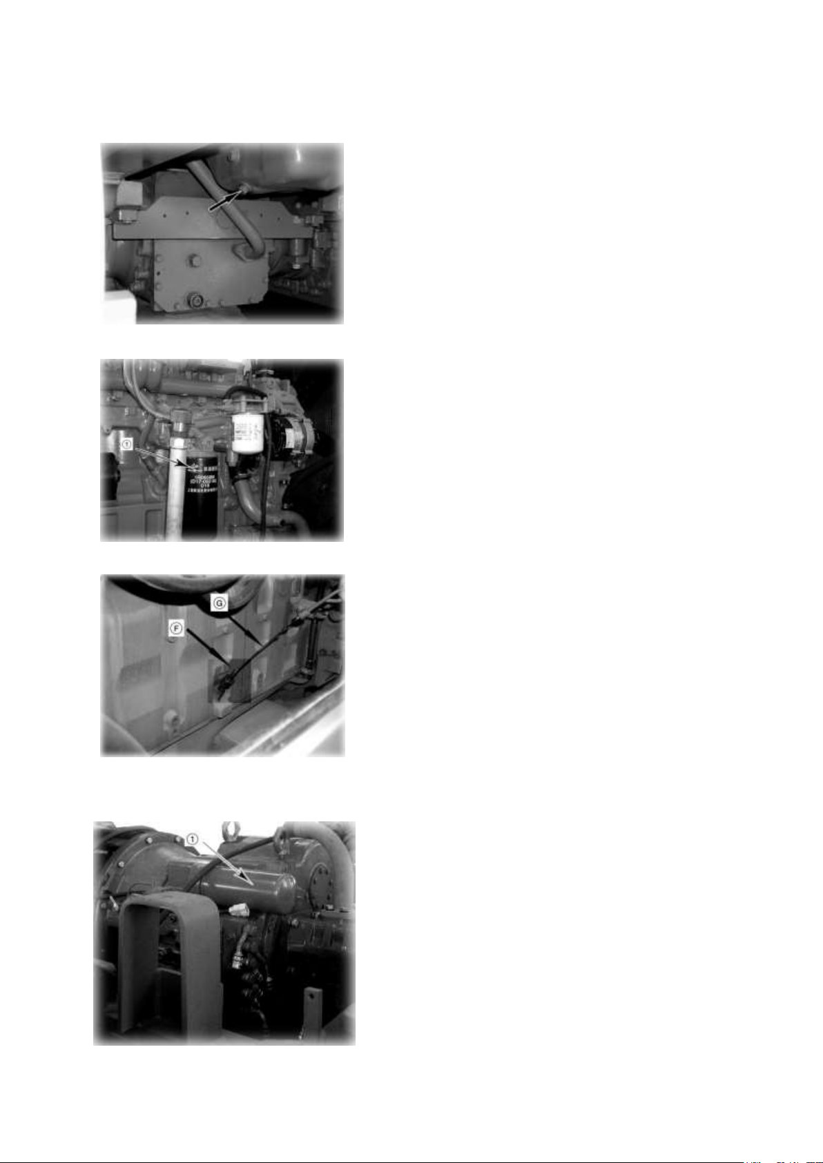
b. ENGINE OIL PAN AND FILTER
1. Loosen drain plug to drain oil. After draining, tighten
it.
2. Using a filter wrench, remove cartridge (1) of the
fuel oil filter by turning it counter clockwise.
3. Clean the filter base and fill a new filter cartridge
with fuel oil. Then, apply a thin coat of grease to the
seal.
4. After replacing the cartridge, fill oil through oil filler
(F).
5. Then idle the engine for a while, and use dipstick (G)
to check oil level.
★The type of lubricant used depends on the ambient
temperature. Select according to the table FUEL,
COOLANT AND LUBRICANTS.
★Refill capacity : 17L
★Be sure to use a genuine POWERTRAC cartridge.
★Use API category CD class oil. If CC class oil must
be used, change the oil and replace the oil filter at half
the interval.
1. Remove filter case (1) and discard.
2. Install a new filter.
★Use genuine POWERTRAC filter.
c. TRANSMISSION FILTER
10- 59
Page 60
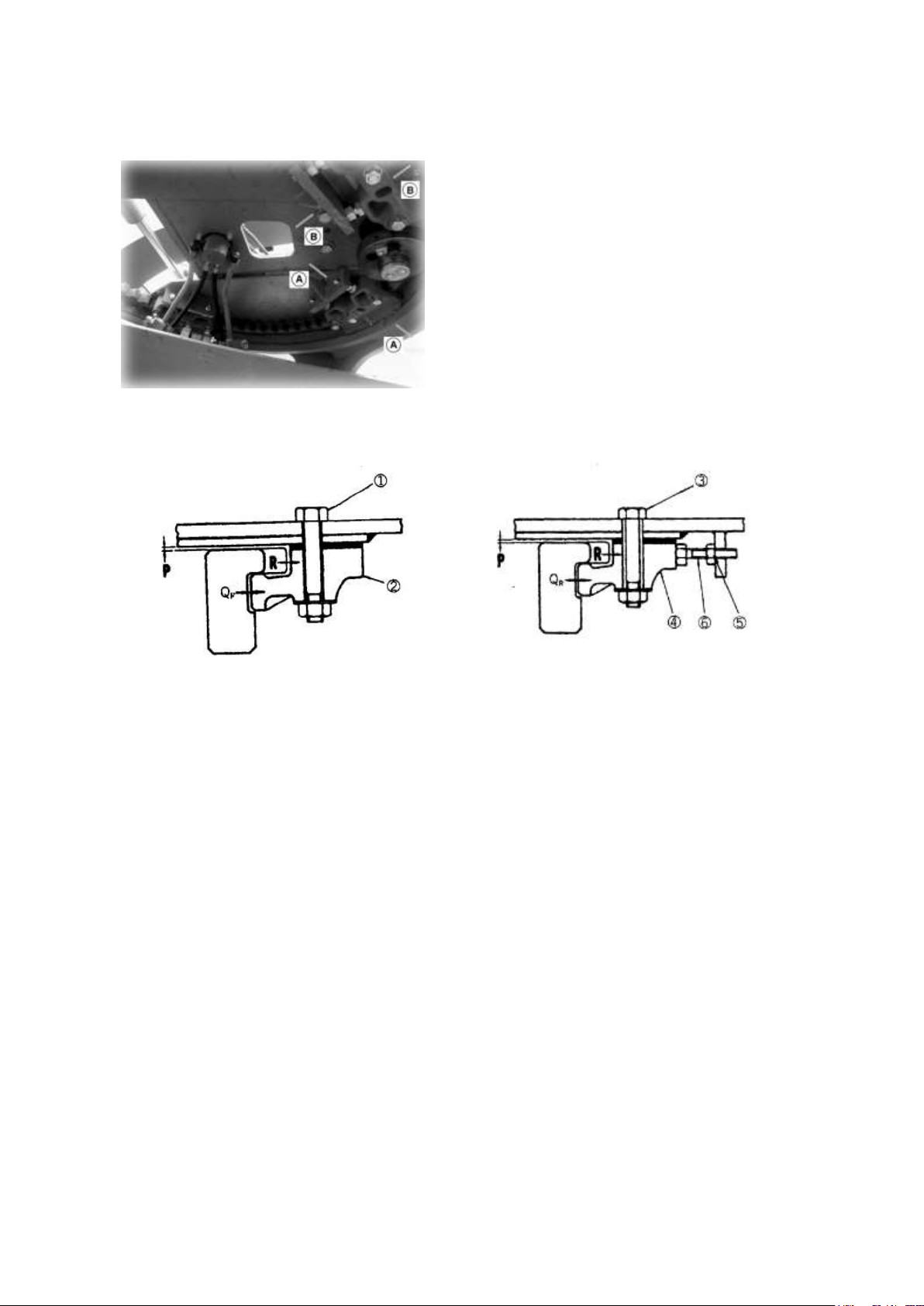
d. CIRCLE GUIDE
CHECKING
With the blade raised from the ground, check the
circle guide clearances at the portions (P) and (Q),
using the feeler gauge.
Standard clearances at the portions (P) is 1.5±
0.5mm
Standard clearances at the portions (Q):
(Q)F =0and(Q)R=1.5mm or (Q)F= (Q)R=1mm
F: Front R: Rear
Section A-A Section B-B
ADJUSTING
Rest the blade on the ground.
1. To adjust the clearance at portion (P), loosen bolt (1) and (3) and adjust thickness of
shims for circle guide (2) and (4). Two kinds of shims different in thickness (1mm and
0.5mm) are provided.
2. To adjust the clearance at portion (Q), first loosen the bolt (1), push the circle guide (2)
rearward to make the clearance (Q)F zero, and temporarily tighten the bolt (1).
3. Then, loosen the bolt (3). Loosen lock nut (5) and bolt (6), fastening the bolt (6) and
turn in the bolt to push the circle guide (4) until the clearance (Q)R becomes zero. (Be
sure to equally tighten the right and left bolts (6).
4. With the clearance (Q) R kept in zero, back the bolt (6) half rotation, and tighten the lock
nut (5). Back the circle guide (4) until it comes into contact with the bolt (6) and tighten
the bolt (3).
★When either of the following conditions arises, replace the circle guide:
1. Clearance at portion (R) has decreased to zero.
2. Clearance between the circle tooth top and circle reverse pin gear tooth bottom has
decreased to zero or clearance between the circle tooth bottom and the circle reverse
pin gear tooth top has decreased to zero.
10- 60
Page 61
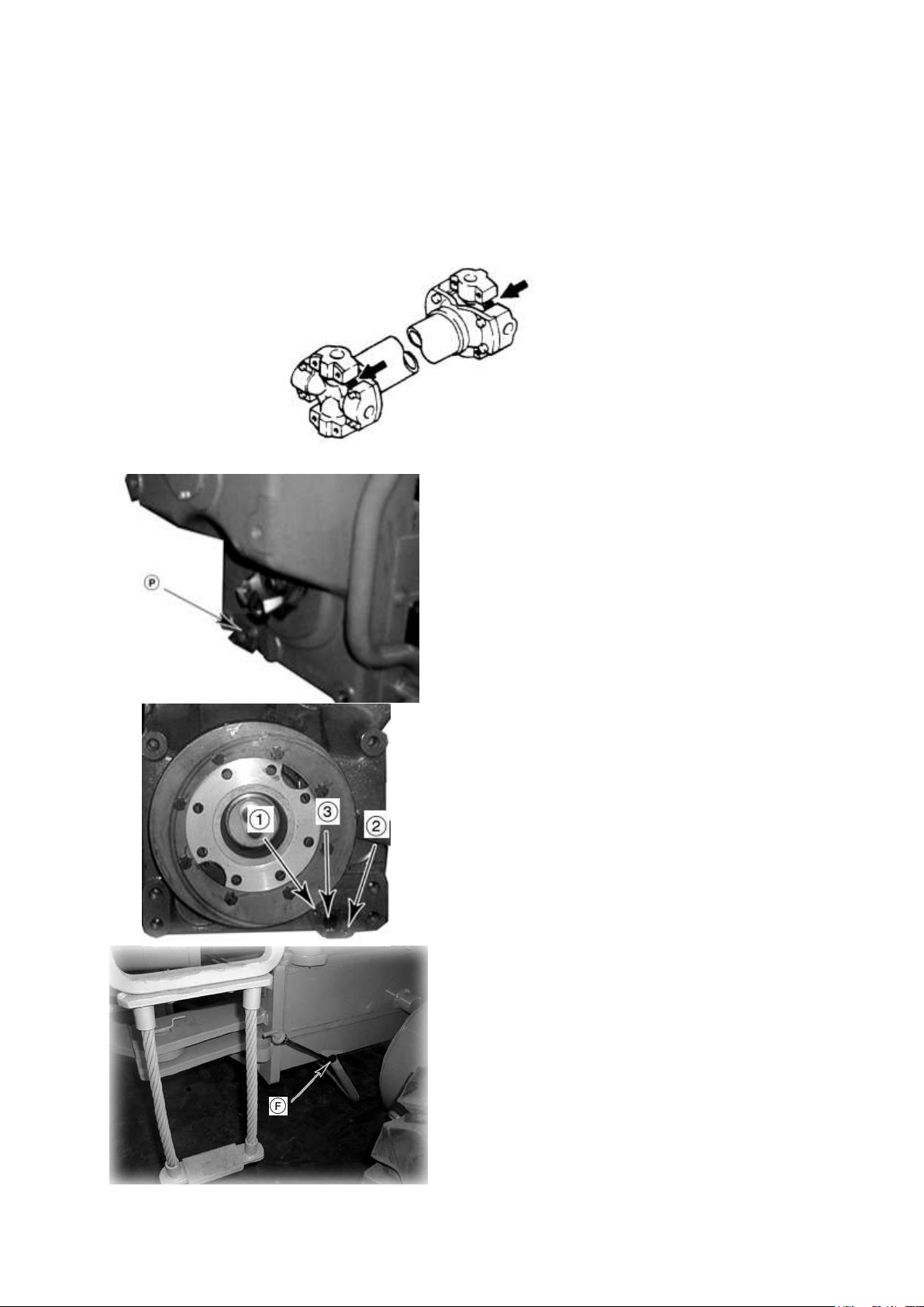
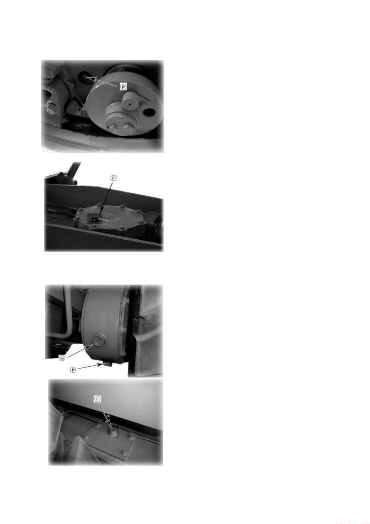
1. Remove drain plug (P). After draining oil,
retighten drain plug.
2. Remove bolt (1), (2) and over (3). Wash out
dust with diesel fuel.
3. After cleaning, install strainer. OR Install a new
filter.
4. Refill engine oil in specified amount through
filler (F). For refilling procedure see the section
EVERY 1000 HOURS SERVICE.
★The type of lubricant used depends on the
ambient temperature. Select according to the table
FUEL, COOLANT AND LUBRICANTS
★Refill capacity: 28 L
EVERY 1000 HOURS SERVICE
Maintenance for every 50, 250 and 500 hours should be carried out at same time.
a. LUBRICATING
Apply grease to the grease fittings shown by arrows.
Drive shaft (2 points)
b. TRANSMISSION CASE
10- 61
Page 62
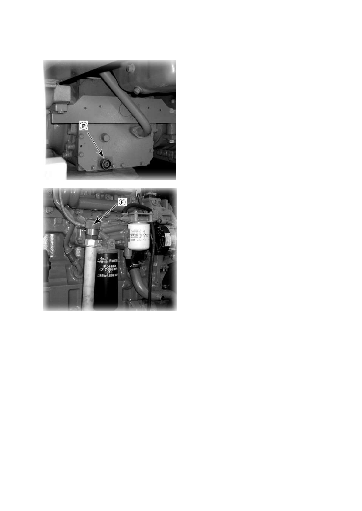
c. FINAL DRIVE CASE
1. Remove drain plug (P) to drain oil. After
draining tighten it.
2. Refill the oil through filler (F) up to the
prescribed level.
3. For the refilling procedure, see the item
“EVERY 250 HOURS SERVICE”.
★The type of lubricant used depends on the
ambient temperature. Select according to the
table FUEL, COOLANT AND
LUBRICANTS
★Refill capacity: 17 L
10- 62
Page 63
d. CIRCLE REVERSE CASE
1. Remove drain plug (P) to drain oil. After
draining tighten it.
2. Refill the oil through filler (F) up to the
prescribed level.
3. For the refilling procedure, see the item
“EVERY 250 HOURS SERVICE”.
★The type of lubricant used depends on the
ambient temperature. Select according to the
table FUEL, COOLANT AND
LUBRICANTS
★Refill capacity: 4 L
★A gun-metal gear is assembled inside this
case, so the drained oil is different from the
oil drained from other parts, because it will
contain gold-colored particles. However, this
is not an abnormality.
1. Remove drain plug (P) to drain oil. After
draining tighten it.
2.Remove drain plug (G), then add oil
through oil filler (F) until oil comes out from
level plug (G)
3. For the refilling procedure, see the item
“EVERY 250 HOURS SERVICE”.
★The type of lubricant used depends on the
ambient temperature. Select according to the
table FUEL, COOLANT AND
LUBRICANTS
★Refill capacity: 45L(One side)
e. TANDEM DRIVE CASE
10- 63
Page 64
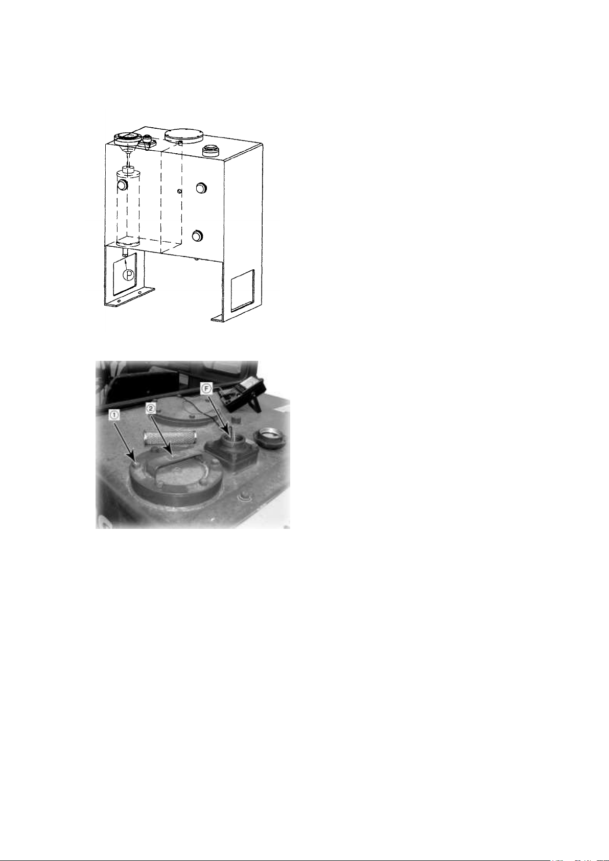
f. HYDRAULIC TANK AND FILTER
Set the machine in position as follows to the
check the oil lever.
·Return the leaning of the front tires to the
upright position and face the wheels straight
to the front.
·Set the front frame and rear frame facing
straight (articulated angle).
·Return the draw bar side-shift and blade
side-shift to the center of the machine, set the
blade at right angles to the chassis and lower
it lightly to the ground.
1. Stop the engine and remove drain plug (P). After draining oil, tighten drain plug.
2. Remove bolts (1) and cover (2) and take out element. Then clean the inside of the filter
housing together with the other remove parts. After cleaning, replace with a new element.
3. Refill oil in specified amount through filler (F).
4. For refilling procedure, see the item “EVERY 250 HOURS SERVICE”.
★The type of lubricant used depends on the ambient temperature. Select according to the
table “FUEL, COOLANT AND LUBRICANTS”.
★Refill capacity: 47 L
★Use genuine POWERTRAC elements.
10- 64
Page 65
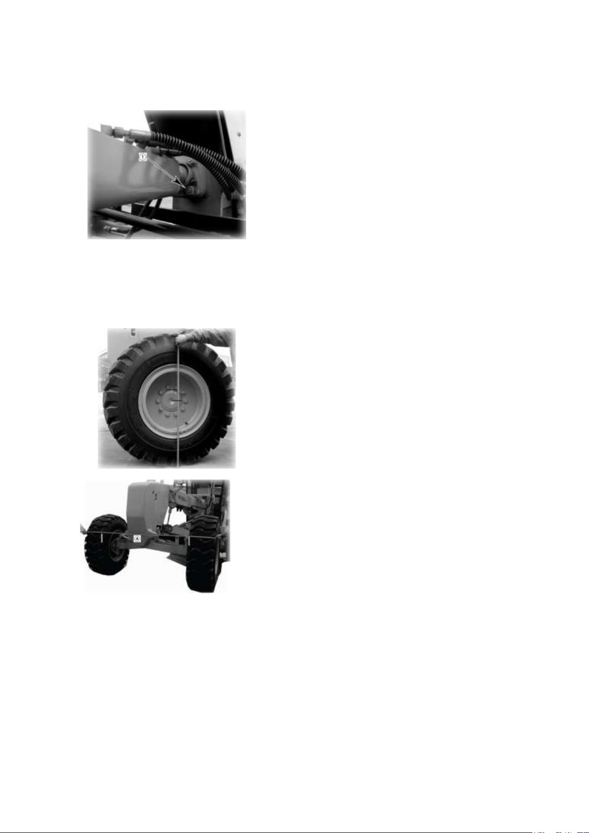
Check ball joint connecting nuts (1) at the
front of the draw bar for loosening. If the
connecting portions are loose, retighten them.
1. Park the grader on a level ground without
steering and leaning the wheels. Be sure to
drive straight at least a few meters before
parking.
2. Measure the height from the ground to the
center of the front wheel axle.
3. Mark on the front tire surfaces with the
same measure taken by the above procedure.
4. Measure the distance between the two
marks on the right and left tires. This distance
in named “A”.
g. DRAW BAR FRONT BALL JOINT
h. TOE-IN
Check toe-in and adjust it so that no sideslip is caused. When no side slip tester is available,
use the following procedure.
HOW TO MEASURE TOE-IN:
10- 65
Page 66
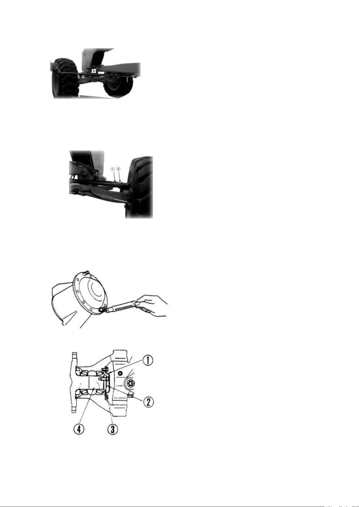
5. Drive the grader at a low speed and shift
backward the mark on the tore. Stop the
grader when the mark´s height from the
ground surface has become equal to the same
value measured in the procedure 2.
6. Measure the distance between the two
marks. This distance is named “B”.
1. Loosen nut (2). Turn the tie rods with a
wrench put on square portion (1). Then,
tighten the lock nuts.
2. Toe-in increases when the wrench is turned
in the direction shown by the arrow, and vice
versa. The value of toe-in varies by 6mm
when the tie rods are turned 1/3 rotation in
the opposite direction to each other.
1. The bearing play is normal if the front
wheel is rotated smoothly with 8 to 12kg of
pulling force.
2. If the inspection shows that there is play, or
that the rotating force is small, adjust as
follows.
3. Remove cover (1). Select proper shims (2)
and set them temporarily. Tighten bolt (3) and
rotate the shaft by more than 3 revolutions
each for clockwise and count-clockwise
directions.
4. Loosen bolt (3). Reduce the number of
shims (take out a t=0.1 or t=0.3 shims),
and decide the thickness of shims properly so
that the pulling force of the spring balance
becomes to 8 to 12kg. This measurement of
the pulling force should be done after shaft
(4) has been rotated by more than 3 turns and
after the bearing has ceased rotating.
HOW TO ADJUST TOE-IN
When toe-in B-A is adjusted to 5±1mm of standard range, side slip is decreased to zero.
If any value other than the standard range is measured, adjust toe-in using the following
procedure:
★Keep the front axle horizontally without any leaning.
i. FRONT WHEEL BEARING PLAY
Raise the front wheels off the ground, using the blade or scarifier as a jack. Check hub turning
torque with a spring balance hooked to a hub bolt.
★Also wait until the bearing gets down to normal room temperature for adjustment.
10- 66
Page 67
1. Support the front axle on a block to raise
the front wheel off the ground. Remove the
wheels.
★When raising the front wheels, securely
apply the parking brake and rest the blade and
scarifier on the ground.
1. Remove breather (1) from the cylinder.
2. Rinse the whole breather in diesel oil or
flushing oil, dry with compressed air, then
install again in the cylinder block.
★Before taking the breather out of place,
wipe the dust off the surrounding area.
★When restoring the element to its original
position, be sure to coat the new 0-ring with
engine oil.
EVERY 2000 HOURS SERVICE
Maintenance for every 50, 250, 500 and 1000 hours should be carried out at the same time
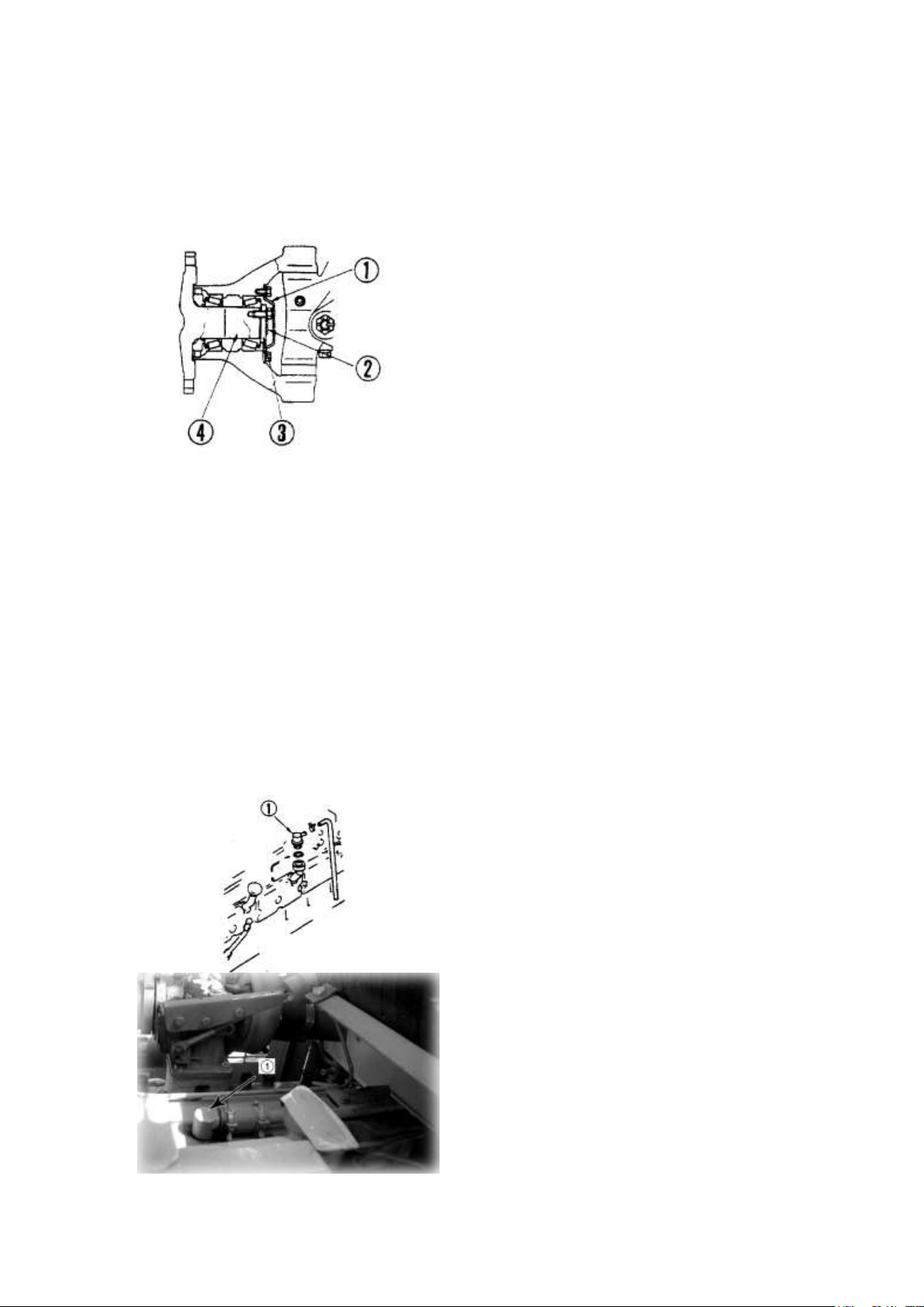
a. FRONT WHEEL BEARING (GREASE BOTH RIGHT AND LEFT SIDES)
2. Remove cover (1), lock (2), holder (3) and hub shaft (4).
3. Clean the axle and bearing. Thoroughly wash out waste grease from the hub interior. Fill
the half space of the cavity with fresh grease.
4. Replace the hub seal and the spacer.
★Before installing the hub seal, coat the lip surfaces and sliding surfaces with grease and fill
the space between lips with grease.
★Press ample quantity of grease into the axle and bearing. Heat up grease around the bearing.
Install the hub.
5. For adjustment of the turning force after installing the hub shaft, refer to the section on
inspection and adjustment of play in the front wheel bearing.
b. ENGINE BREATHER
10- 67
Page 68

c. TURBOCHARGER
Excessive carbon or oil sludge adhering to turbocharger blower impeller may lead to
deterioration of normal charger performance, and possible damage. Have turbocharger
cleaned by POWERTRAC distributor.
1. Remove the turbocharger oil filler pipe and drain pipe, then remove the intake air pipe
connector and blower housing so that the blower impeller can be seen.
2. Using light oil as a cleaning agent, remove the carbon, sludge and other dirt from the
blower impeller. Do not use a wire brush or other tool which may damage the impeller.
3. Pour in light oil through the turbocharger oil filler and rotate the blower impeller several
times to wash out the sludge.
4. Rotate the impeller by hand at least one turn at speed to check that there is contact noise or
catching inside.
If the impeller does not turn smoothly, contact your POWERTRAC distributor of repair or
replacement.
5. If there is no abnormality, dry off the light oil with compressed air after inspection, then
add engine oil.
d. ALTERNATOR AND STARTING MOTOR
The brush may be worn, or the bearing may have run out of grease, so please contact your
POWERTRAC distributor for inspection or repair.
★ If the engine is started frequently, carry out inspection every 1000 hours.
e. ENGINE VALVE CLEARANCE
As special tool is required for removing and adjusting the parts, you shall request
POWERTRAC distributor for service.
f. VIBRATION DAMPER
Check that there are no cracks in the damage rubber. If there is any abnormality, contact your
POWERTRAC distributor for repairs.
10- 68
Page 69

EVERY 4000 HOURS SERVICE
★Maintenance for every 50, 250, 1000 and 2000 hours should be carried out at the same
time.
a. WATER PUMP
Check that there is no play in the pulley, grease leakage, water leakage, or clogging of the
drain hole. If any abnormality is found, please contact your POWERTRAC distributor for
disassembly and repair or replacement.
10- 69
Page 70

Type of antifreeze solution
Cleaning inside of cooling
system and changing cooling
Replacing corrosion Resistor
Non permanent type
antifreeze containing
ethylene glycol (All season
type)
Every year (autumn) or every
2000hours whichever
comes first
Every 1000hours and when
cleaning the inside of the
cooling system and when
changing coolant
Non permanent type
antifreeze containing
ethylene glycol (Winter, one
season type)
Every 6 months (spring,
autumn) (Drain antifreeze in
spring, add antifreeze in
autumn)
When not using antifreeze
Every 6 months or every
1000hours whichever comes
first
WHEN REQUIRED
a. CLEAN INSIDE OF THE COOLING SYSTEM
Clean the inside of the cooling system, change the coolant, and replace the corrosion resistor
according to the table
★ Stop the machine on level ground when cleaning or changing the coolant.
★ Use a permanent type of antifreeze. If, for some reason, it is impossible to use permanent
type antifreeze, use an antifreeze containing ethylene glycol.
★ Be sure to replace the corrosion resistor cartridge.
★ Use city water for the cooling water.
If river water, well water or other such water supply must be used, contact your
POWERTRAC distributor.
▲ Antifreeze is flammable, so keep it from any flame.
·Add antifreeze in the cooling water
When deciding the ratio of antifreeze to water, check the lowest temperature in the past, and
decide from the mixing rate table.
It is actually better to estimate a temperature about 10℃ lower when deciding the mixing
rate.
According to the mixing rate of the actual atmospheric temperature, please refer to the mixing
rate directions of the antifreeze about the mixing rate of water and antifreeze. The total
volume of cooling system is about 45L.
★We recommend use of an antifreeze density gauge to control the mixing proportion.
10- 70
Page 71
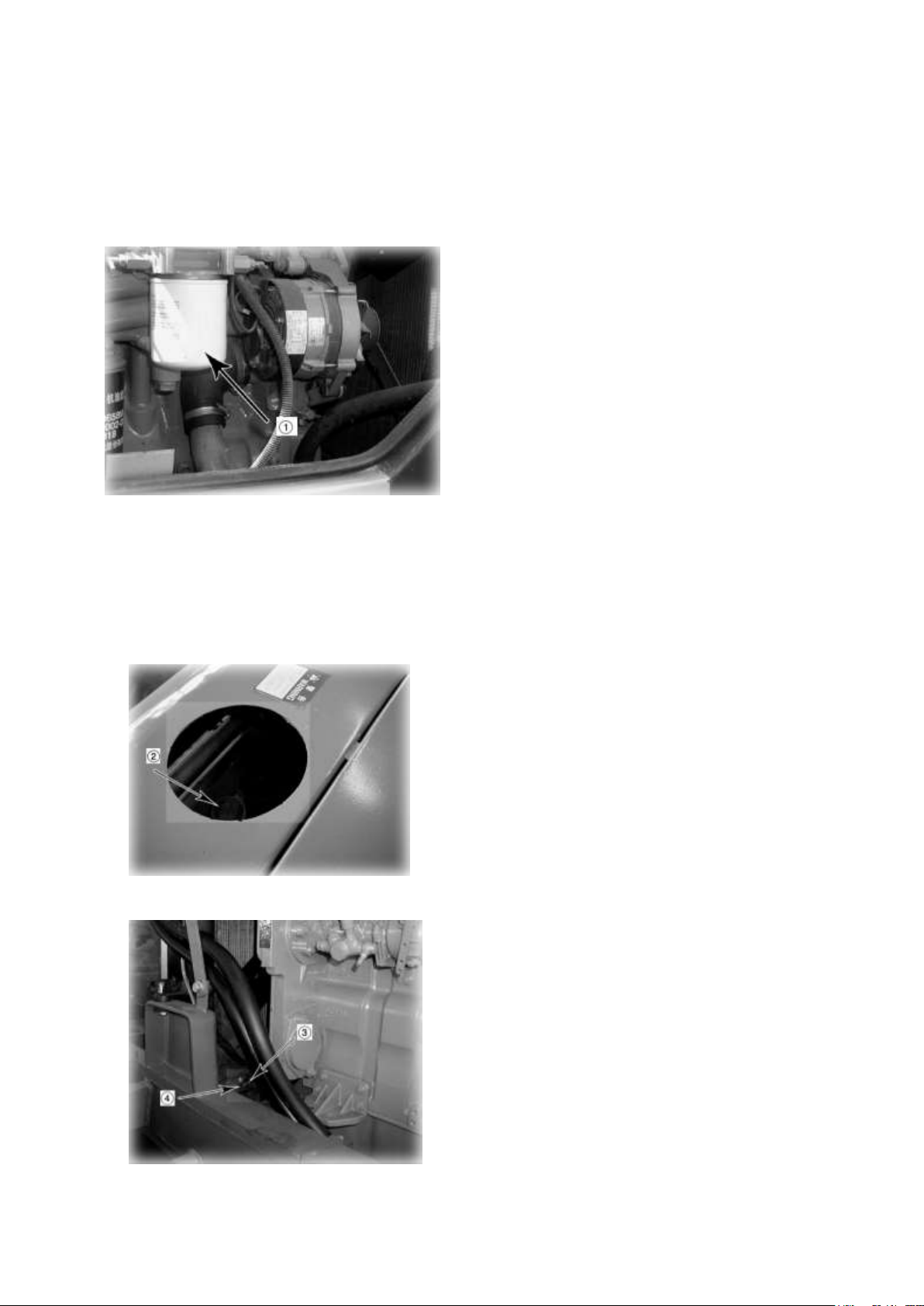
3. Open drain valve (3) at the bottom of the
radiator and plug (4) on the side of cylinder
block to drain off the cooling water.
4. Drain off all the water, then close up drain
valve (3), plug (4), and pour in soft water (ex:
city water) up to the vicinity of the water
filler.
5. When the water reaches the vicinity of the
water filler, put the engine at low idling, open
drain valve (3) and plug (4), then pass water
through the cooling system for 10 minutes.
7. After draining water, use a flushing agent
to clean.
8. After washing the cooling system, drain off
all the water, then close up drain valve (3)
and plug (4), and pour in soft water (ex: city
water) up to the vicinity of the water filler.
9. When the water reaches the vicinity of the
water filler, put the engine at low idling, open
drain valve (3) and plug (4), then pass water
through the cooling system until clean water
comes out from drain valve (3) and plug (4).
10. When the water becomes completely
clean, stop the engine, close drain valve (3)
and plug (4).
11. Replace the corrosion resistor cartridge
and open corrosion resistor valve (1).
★For details of replacement of the corrosion
resistor, see the maintenance section.
CORROSION RESISTOR
1. Stop the engine and tighten up corrosion resistor valve (1).
2. Turn cap (2) slowly until it comes off.
★When doing this, adjust the inflow and outflow of water so that the radiator is always full.
6. After flushing with water, stop the engine. Close drain valve (3) and drain plug (4) after
draining water.
WATER FILLER
DRAIN PLUG (BOTTOM OF RADIATOR)
10- 71
Page 72
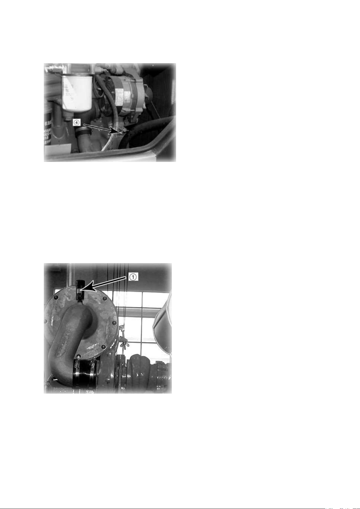
12. Supply water up to the vicinity of the
water filler.
13. Run the engine for 5 minutes at low idling
to eliminate air trapped in the cooling system,
and run the engine for 5 minutes at high
idling. (Leave water filler cap (2) off during
this operation)
CHECKING
Whenever the red piston in dust indicator (1)
appears, clean the air cleaner out element.
Stop the engine when cleaning the element.
DRAIN PLUG (CYLINDER BLOCK)
14. Stop the engine and 3 minutes later supply water again up to vicinity of the water filler
and tighten water filler cap (2).
▲ Do not remove the cap while cooling water is hot. Hot water may spout out.
When removing radiator cap, turn it slowly to relieve inner pressure.
b. CHECK, CLEAN AND REPLACE AIR CLEANER ELEMENT
10- 72
Page 73
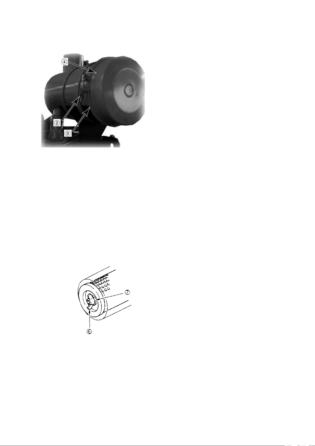
CLEANING OR REPLACING OUTER
ELEMENT
1. Loosen wing bolt (2) and clean (3) and
remove cover (4). Then remove outer
element.
2. Clean the air cleaner body interior and the
removed cover.
3. Clean and inspect the element (see the item
“Cleaning outer element” for cleaning
procedure).
REPLACING INNER ELEMENT
1. First remove the cover and the outer
element, and then remove the inner element.
2. Place the cover over the air intake part to
prevent dust entering.
Clean the air cleaner body interior, and then
remove the cover from the air intake port.
4. Push the dust indicator reset button to return the red piston to the original position.
★ Replace the outer element which has been cleaned 6 times repeatedly or used throughout a
year. Replace the inner element at the same time.
★ Replace both inner and outer elements when the dust indicator red piston appears soon
after installing the cleaned outer element even though it has not been cleaned 6 times.
★ Remove one seal from the outer element. The number of times the outer element has been
cleaned can be seen by the number of remove seals.
★ Check inner element mounting nuts for looseness and, if necessary, retighten.
★ When inspecting or cleaning the air cleaner, remove evacuator valve and clean with
compressed air.
★ Replace seal washer (7) or wing nut (6) if they are broken.
3. Fit a new inner element and tighten it with nuts.
4. Install the outer element and the cover. Push the dust indicator reset button.
NOTE: Do not attempt to reinstall a cleaned inner element.
▲Do not clean or replace the air cleaner element with the engine running.
10- 73
Page 74
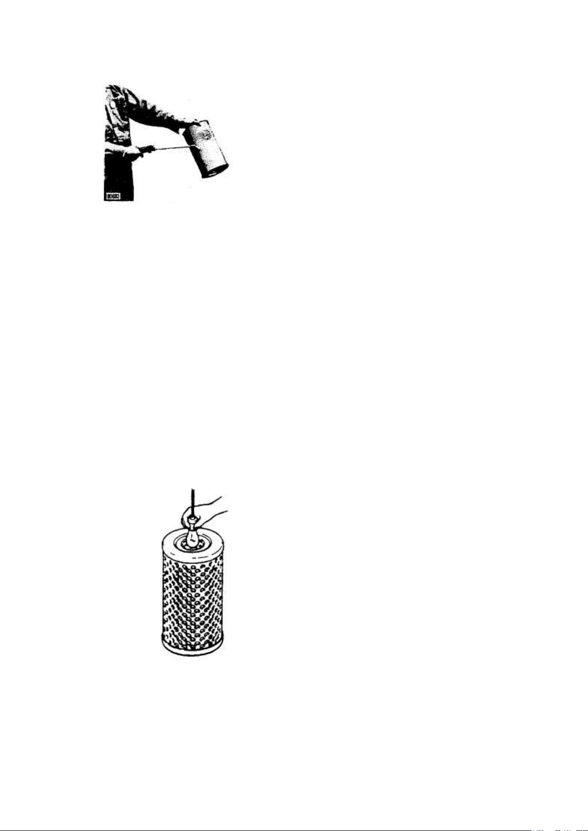
CLEANING OUTER ELEMENT
WITH COMPRESSED AIR:
Direct dry compressed air(less than 7kg/cm²)
to element from inside along its folds, then
direct it from inside along its folds and again
from inside, and check element.
★If element is usable, wrap it and store it in
dry place.
★Do not use element whose folds or gasket
or seal are damaged.
★When cleaning element, do not hit it or
beat it against something.
▲When using compressed air, wear safety glasses and other things required to maintain
safety.
THE FOLLOWING METHODS SPARE PARTS.
WITH WATER:
Dash city water (less than 3kg/cm²) on element from inside along folds, then from outside
and again from inside. Dry and check it.
WITH CLEANING AGENT:
For removing oils and fats as well carbon etc. attach on the element, the element may be
cleaned in lukewarm solution of mild detergent, then rinsed in clean water and left to drip dry.
★ Drying can be speeded up by blowing dried compressed air (less than 7kg/cm²) from the
inside to the outside of the element .
Never attempt to heat the element.
★ Using warm water (about 40℃) instead of soapy water may also be effective.
★ If small holes or thinner parts are found on element when it is checked with an electric
bulb after cleaning and drying, replace the element.
10- 74
Page 75

TROUBLE SHOOTING GUIDE
This guide is not intended to cover every condition, however many of the more common
possibilities are listed.
ENGINE
Engine oil pressure pilot lamp does not go off immediately after starting engine.
·Add the oil to the specified level.
·Replace the oil filler cartridge.
·Check oil leakage from the pipe or the joint.
·Replace the lamp .
Steam is emitted from the top of the radiator (the pressure valve).
Engine cooling water temperature gauge indicates red range.
·Supply the cooling water and check leakage.
·Adjust fan belt tension.
·Wash out inside of cooling system.
·Clean or repair the radiator fin.
·Replace the thermostat.
·Tighten the radiator cap firmly or replace the gasket of it.
·Replace the water temperature gauge
Engine cooling water temperature gauge indicates white range.
·Replace the thermostat.
·Replace the engine cooling water temperature gauge.
The engine does not start when the starting motor is turned over.
·Add fuel.
·replace the injection pump and the nozzle.
·Repair where air is leaking into fuel system.
·Check the valve clearance.
·Check the engine compression pressure.
·Refer to the section of electrical system.
Exhaust gas is white.
·Adjust to specified oil quantity.
·Replace with specified fuel.
Exhaust gas occasionally turns black.
·Clean or replace the air cleaner element.
·Replace the nozzle.
·Check engine compression pressure.
10- 75
Page 76

Combustion noise occasionally changes to breathing sound.
·Replace the nozzle.
Unusual combustion noise or mechanical noise.
·Replace with specified fuel.
·Check over-heating.
·Replace the muffler.
·Adjust the valve clearance.
ELECTRICAL SYSTEM
Lamp does not glow brightly even when engine runs at high speed.
Lamp flickers while engine runs.
·Check for loose terminals and open-circuit wiring.
·Adjust belt tension.
Charge lamp does not go out even when engine runs at high speed.
·Replace the charge lamp.
·Replace the alternator.
·Check and repair the wiring.
Unusual noise is emitted from the alternator.
·Replace the alternator.
Starting motor does not turn when starting switch is turned on.
·Check and repair the wiring.
·Charge the battery.
The pinion of the starting motor keeps going in and out.
·Charge the battery.
Starting motor turns the engine sluggishly.
·Charge the battery.
·Replace the starting motor.
The starting motor disengages before the engine start up.
·Check and repair the wiring.
·Charge the battery.
Heater signal does not glow red.
·Check and repair the wiring.
·Replace the heater relay.
·Replace the heater signal.
Outside the electrical intake air heater is not warm when touched with the hand.
·Check and repair the wiring.
·Replace the electrical intake air heater.
10- 76
Page 77

·Check and repair the heater switch.
CHASSIS
Traction is lacking. (Insufficient traveling speed)
·Refer to the section of engine.
·Check transmission.
·Release parking brake level.
Machine falls to start at any gearshift level position.
·Add oil to transmission case.
·Check and adjust transmission.
There is loud noise in the power transmitting system.
·Add oil to transmission case and the tandem case.
Excessive wear of front wheels.
·Adjust toe-in.
Heat generation at front wheel hub.
·Adjust wheel bearing installation nut.
·Apply grease.
Front wheels away while traveling.
·Adjust toe-in.
·Replace steering linkage.
·Equalize tire pressure on each side.
·Check wheel installation.
·Retighten front wheel bearing installation nut.
Steering wheel feels heavy.
·Check front tire pressure.
·Apply grease on each bearing.
·Repair piping.
Steering wheel heavy
·Give equal air pressure to both right and left tires.
·Adjust the mountings for the front wheel bearing.
Steering wheel plays too much.
·Tighten fully the link joint.
Steering wheel rugged
·Filler or replace oil, or disassemble and repair the ball nut.
Parking brake does not operate satisfactorily.
·Adjust brake pad.
·Polish lining surface with sandpaper.
10- 77
Page 78

·Disassemble and clean brake drum.
Excessive blade swing during work
·Adjust shims of ball joint and circle guide.
·Replace side bushing.
·Correct blade rail.
Excessive vibration of the blade when rotating under operation.
·Adjust radial clearance of the circle.
During operation, scarifier vibrates up and down.
·Adjust the shims for the hoist cylinder ball joint.
Work equipment is slow to move by operating the control level.
·Add the oil to the specified level.
Wear of parking brake lining
·Adjust clearance of lining.
10- 78
Page 79
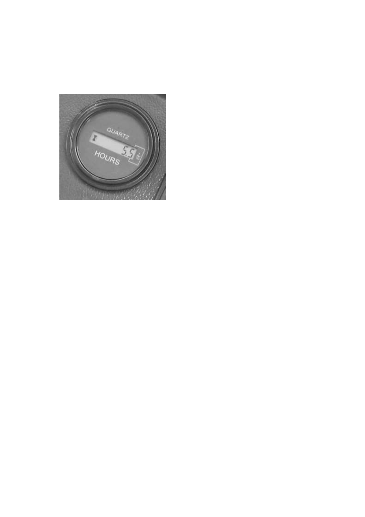
·Record the readings at the start and the end
of work, this is the work record of the
machine.
·This record will indicate when periodical
maintenance is due.
·It also indicates the integrated working
hours when machine problems are
encountered.
SERVICE METER
This meter indicates the integrated work hours. So, use it according to the following
instructions.
★How the meter progresses
The service meter progresses by 1 when the engine is operated for one hour, regardless of the
engine speed.
Consequently, if the engine is running, the service meter will advance even if the machine
does not move.
10- 79
Page 80
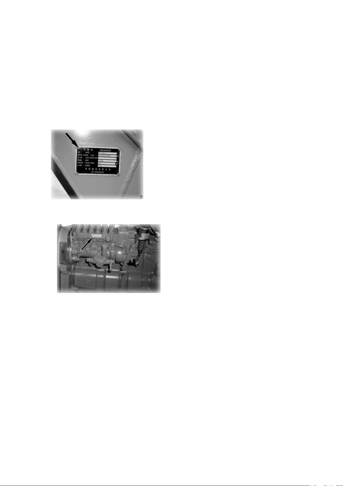
This is seen on the center left of the front
frame.
It is seen on the upper right of the cylinder
block, when seen from the fan side.
MACHINE AND ENGINE SERIAL NUMBERS
When calling for service of machine or when making replacement parts order, be sure to give
your POWERTRAC distributor the machine and engine serial numbers as well as the service
meter reading before mentioned. These numbers are found on the plates shown in the photos
below.
·Location of the machine serial number mark
·Location of the engine serial number mark
10- 80
Page 81

Type
Season
Temperatur
e℃
Standard Code
Oil Grade
Remarks
Fuel oil
Winter
-5~10
GB252-2000 Light
diesel oil
*-10
Fuel Tank
Summer
4~40
*0
Diesel
engine
oil
All
seasons
-10~40
GB11122-1997
Diesel engine
oil(CD)
*15W/40
Domestic
engine
All
seasons
-15~40
SAE API CF-4
Mobil Delvac
Mobil 1300
Imported engine
Torque
converte
r oil
All
seasons
-15~40
Hydraulic
transmission oil
*8 号
Domestic
transmission
and converter
Hydrauli
c oil
Winter
-10~10
GB11118.1-94
Mineral oil and
Synthetic
hydrocarbon type
hydraulic oil(L-HM)
*32
Working
hygraulic
system
Summer
0~40
*46
Gear oil
All
seasons
-10~40
GB13895-1992
Heavy-duty gear oil
GL-5
*85W/90
Domestic drive
axle,balancing
box and
Worm-gear case
Brake
oil
All
seasons
-20~40
GB10830-1998
(DOT-3,SAEJ1703)
(719Synthetic
brake fluid)
Brake system
Grease
All
seasons
-20~40
SH/T0380-1992
Lithium complex
grease
ZL-2H
ZL-3H
Rolling
bearings and
pins
Antifreez
e
All
seasons
-40~40
SH/T0521-1999
Automobile glycol
coolant
-45℃ antifreeze
For export
-15~40
-18℃ antifreeze
For domestic,
with A/C OR
Heater
FUEL, COOLANT AND LUBRICANTS
PROPER SELECTION OF FUEL, COOLANT AND LUBRICANTS
The grader’s oil table in normal state
10- 81
Page 82

Type
Climate
Temperatur
e℃
Standard Code
Oil Grade
Remarks
Fuel oil
Cold
-44~0
GB252-2000Light
diesel oil
-50
Fuel tank
Diesel
engine
oil
Cold
-40~40
SAE API CF-4
Mobil Delvac1
Engine for
expoting grader
Torque
converte
r oil
All
seasons
-40~40
Hydraulic
transmission oil
8D
transmission and
converter for
expoting grader
Hydrauli
c oil
Cold
-38~0
L-HS
Kunlun antiwear
hydraulic oil 32
Working
hygraulic system
Gear oil
Cold
-40~40
GB13895-1992 GL-5
75W/90
Domestic drive
axle
Brake
oil
Cold
-40~40
Mobil Universal
Brake Fluid DOT 3
Mobil brake oil
DOT 3
Brake system
The grader’s oil table in cold regions
10- 82
Page 83

Safety and Operation
10- 83
Page 84
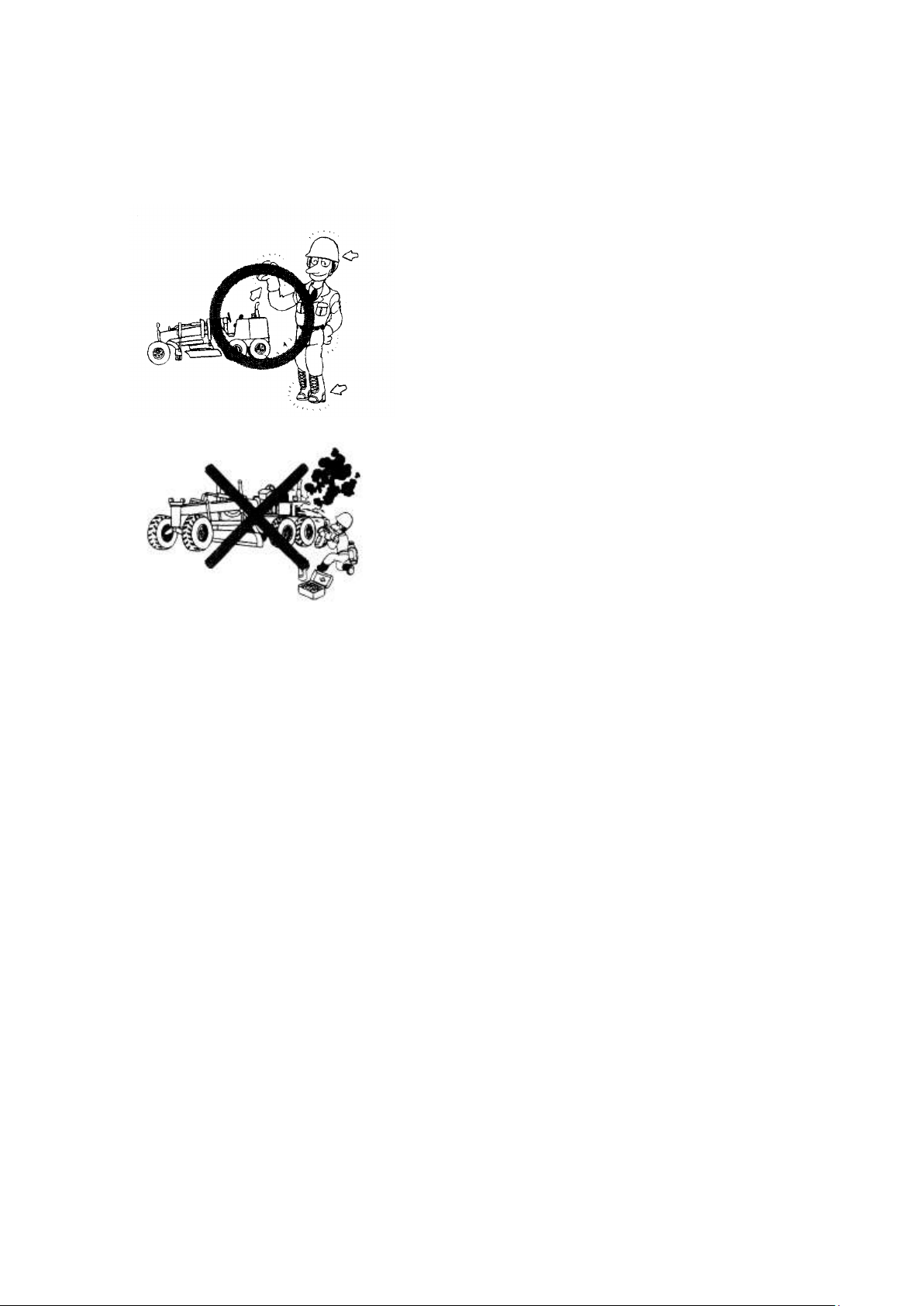
OPERATION GENERAL
·Wear proper clothes
Loose clothes, ornaments or other things that may
possibly contact the control lever or other
machine parts must not be worn. Do not let you
clothes get caught on protruding parts of the
machine. Do not wear oily clothes since they may
catch fire.
· Wear well-fitting helmet, safety shoes and
working clothes. If the nature of the work
requires safety, wear protective goggles or mask,
thick gloves, earplugs or other protection.
·Accidents or injuries are liable to occur when
the operator is careless or slack. It is most
important to bear safe operation in mind at all
times.
SAFETY HINTS
·Take care of your health. Do not drive when tired, or after drinking.
·Learn the prohibitions, cautions and rules about work procedures in the work site.
When there is a leader, fix standard signals and always follow these signals when operating.
·If there should be an accident or fire or any other such unexpected mishap, deal with it
quickly, using the nearest apparatus.
Learn beforehand the locations of the first aid boxes and fire extinguishers and how to use
them. It is also important to know the emergency contact system.
·Learn about the safety devices on your own machine and about how to use them. Confirm
that they are correctly attached in the prescribed position.
Such safety devices include:
★Canopies
★Guards
★Protective Devices
★Roll-over Protective Structures
★Seat Belts, etc.
·Take care not to get caught by protruding parts of the machine. Do not wear oil-stained
clothing because it is likely to catch fire.
·Keep fire away from stored fuel, lubricants and anti-freeze.
10- 84
Page 85
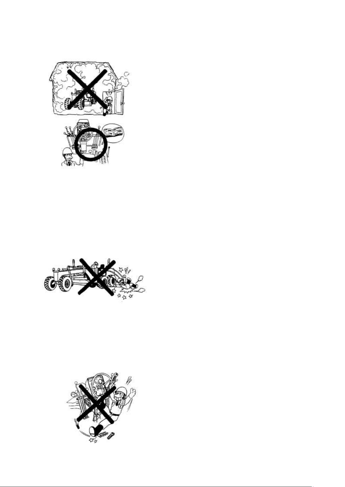
·Exhaust gas is dangerous. When running the engine for
long periods in a poorly ventilated area, there is a danger
of gas poisoning, so open the windows or doors to ensure a
good supply of fresh air.
·Read the Operation and Maintenance Manual carefully.
Learn how to use the control devices, gauges and warning
devices. Be sure you understand the meaning of the
Caution plates. Remember the checkpoints and checking
method for engine oil, fuel, cooling water and hydraulic
oil levels.
·When working on a road, pay attention to the safety of
passing vehicles and pedestrians. If necessary, assign a
signalman or provide temporary barricades.
·When getting on or off the machine, use the hand-rail and
step provided. Do not jump or down from the machine.
·Do not leave parts or tools lying around in the vicinity of
or on the floor of the operator´s compartment. Keep
everything in its proper place.
·Before starting the machine, perform all necessary checks as stated in the Operation and
Maintenance Manual.
BEFORE STARTING OPERATION
·Examine the lay of the land and the kind of oil at the work site to determine the dangerous
points and the best method of operation. Proceed with the work only after making safety
arrangements about the dangerous points.
·Inspect leakage from the fuel, lubricating and hydraulic system. Repair any fuel or oil
leakage, and wipe off all dirty oil.
·Check that tire inflation pressure is standard, that hub nuts are not loosened, and that no
other parts are damaged or missing. Machines having such failures should not be operated.
·Wipe off thoroughly any grease, oil or mud on the step, handrail, floor or control levels.
Failure to do this may cause you to slip.
·Check the level of the fuel, lubricants and cooling water. Extinguish cigarettes before
checking or replenishing. Check that the radiator cap and each oil filler caps or plugs are
firmly tightened.
·Adjust the operator´s seat until it is in the most comfortable position for operating.
·If a seat belt is provided, always use it. If the belt is damaged or worn, replace it with a new
one.
10- 85
Page 86
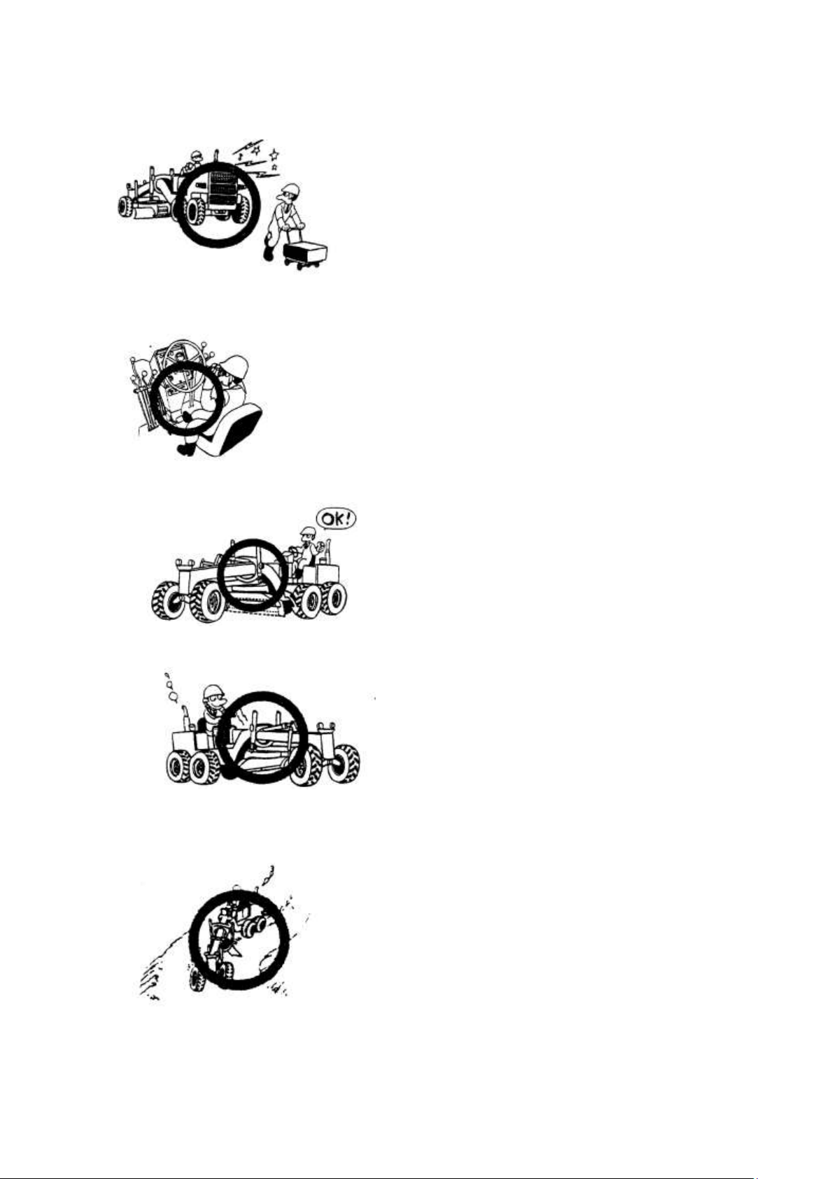
·To ensure the safety of workers near the machine, always
sound the horn to warn them before starting the engine and
moving the machine. Be particularly careful to check that
the rear is clear before backing the machine.
·Combustible materials such as pieces of wood, dead
leaves, and pieces of paper may cause fire, so inspect the
inside of the engine room and remove them.
·Before starting the engine, confirm that all control levels
are in “NEUTRAL” or “HOLD” POSITION.
·Confirm that all gauges and warning devices
are functioning correctly and that the gauge
readings are within the prescribed range.
·Check the play and travel of each level and
pedal.
·Operate the blade to confirm that they are
functioning normally.
· Move the machine slowly and listen
carefully to the engine or gears to confirm
that they are not making any unusual noises.
·Operate the gear shift level to confirm that the travel speeds for forward and reverse are
functioning normally.
·Choosing a safe place, turn the machine to
the left and right to confirm that the steering
devices are functioning normally.
· If these tests reveal anything wrong,
however slight it may be ,contact the man in
charge of the machine and operate the
machine only after obtaining his permission.
AFTER STARTING ENGINE
10- 86
Page 87
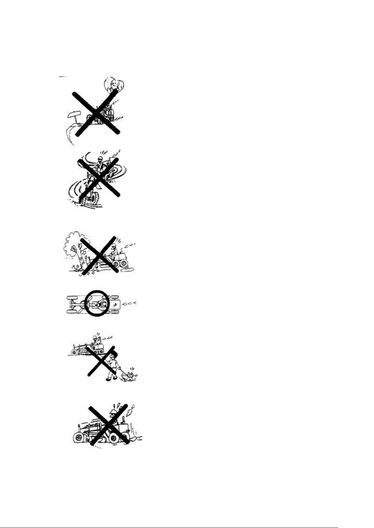
·Always concentrate. It is extremely dangerous to allow yourself
to be distracted or to think of other things when operating a
machine.
In dangerous place, or where there is restricted visibility, it is
important to get down from the machine and confirm whether it
is safe before continuing work.
·The work area should be made as flat as possible. If the work
area is flat, operation is made much easier and this reduces
operator fatigue.
·The machine should always be operated at a speed where it can
be correctly controlled. Never do the following:
★Speeding
★Sudden starting, sudden braking, sudden turning.
★Snaking
★Coasting
·Be careful of those around you, and always confirm that there is
no person or obstacle in the way before driving or turning the
machine.
·Always operate slowly in crowded places. On haul roads or in
narrow places, give way to loaded vehicles.
·Raise each work piece of equipment as high as possible and
keep the blade within the machine width while traveling.
Maintain the specified traveling posture.
· Do not control the vehicle speed by pressing the brake as it
will overheat the brake disc.
·Do not allow unauthorized persons into wok area.
·Always be aware of the operating capacity of the machine.
Using the machine to do work beyond its capacity will not only
damage the machine, but may even cause unexpected accidents.
DURING OPERATION
10- 87
Page 88
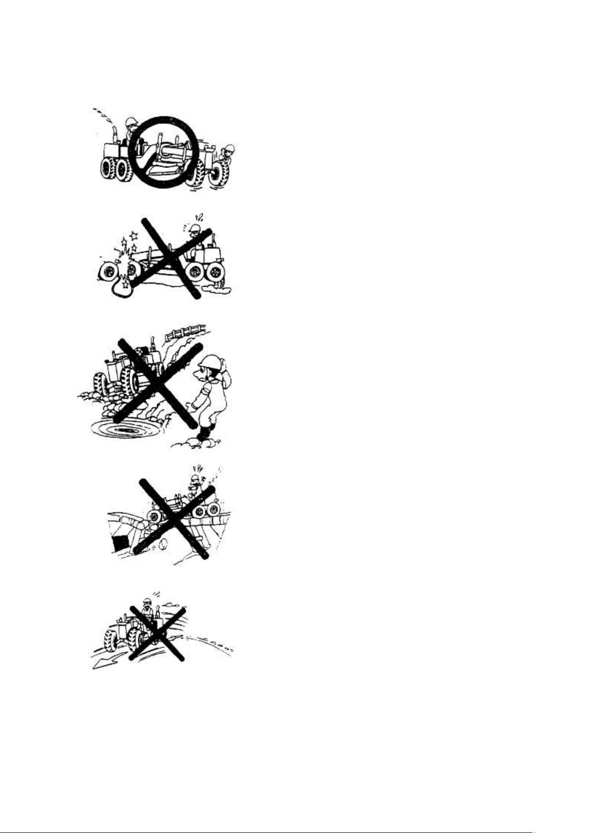
·The machine condition can be judged from many factors.
Changes in the gauges, sound, vibration, exhaust gas color or
response of the control levels can indicate the occurrence of
some disorder. If any disorder occurs, park the machine
immediately in a safe place and take appropriate action. Be
especially careful in the case of a fuel leak, as there is danger
of fire.
·If the machine breaks down and needs to be towed, first
confirm that the brakes are working properly, and then tow,
using a wire rope or any other suitable towing equipment.
·When parking the machine after discontinuing work, put the
gear shift level into “NEUTRAL”, apply the brake lock,
lower the blade , scarifier and ripper to the ground and put all
safety levers into “LOCK”, position. Never leave the
operator´s seat without switching the engine off.
·When continuing operations after rain, remember that
conditions will have changed from those before the rain
started, so proceed with caution.
·Be particularly careful when approaching the shoulder of
the road or cliffs, as they may have been loosened by the rain
·Check the load of limits of bridges before crossing.
·When operating on uneven ground, drive at low speed as
possible and avoid sudden changes in direction.
·When operating at the edge of a cliff or on the shoulder of a
road, remember the following points:
Do not approach the edge of the cliff or road shoulder by
mistake.
·When operating in a place where is danger of the machine
falling over the side, be doubly careful.
10- 88
Page 89
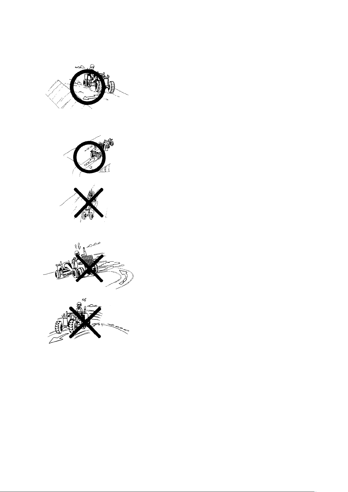
·When working on river embankments or other places made of
piled soil, there is the danger that the weight or vibration of the
machine may cause the machine to sink into the piled soil, so be
extremely careful when operating in such places.
·When driving on a slope, always drive directly up or
down it. Never drive horizontally or diagonally across the
slope, as this may cause the machine to roll over or slip
sideways.
·When going down a slope, use the engine as a brake. If
this is not enough to control the speed of the machine, use
the wheel brake as well. Never coast down a slope with
the gearshift lever in “NEUTRAL” or with clutch
disengaged.
·As far as possible, avoid turning the machine on a slope. It may
cause the machine to roll over or slip sideways.
·Before going up to down a slope, select a travel speed most
suited to the slope. Do not change gear on the slope.
·If the engine stalls on a slope, first use the brake to stop the
machine, then return the gear shift lever to “NEUTRAL” before
starting the engine again.
·When operating on slopes, remember the following points:
·When using the articulation system, be particularly careful not to let the blade damage the
rear tires.
·Operating the articulation system when traveling at high speed may cause the machine to
overturn.
Always perform this operation at a speed below 10km/h.
·Always observe the traffic regulations and leave margin for emergencies.
·When operating in a city area, be sure to locate underground pipes and cables before starting
the machine to prevent them from being broken.
10- 89
Page 90
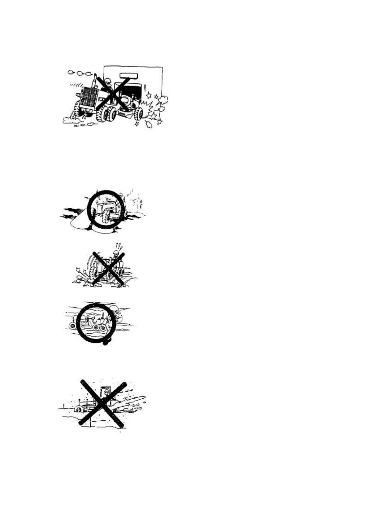
·When operating inside a building always be
sure of the clearances of the ceiling, entrance,
aisles, etc, and the load limit of the floor.
·Never allow other person than the operator
to ride on the machine during operation.
·When passing through a narrow space, be
careful of the side and overhead clearances.
Take special care not to touch any obstacles
·Be sure to arrange an adequate lighting system.
·At night it is very easy to make mistakes in
assuming the distance and height of objects and land.
·When operating in fog, mist or smoke, where
visibility is bad, be especially careful to confirm first
whether operation is safe.
·When visibility drops below safety level, stop work
and wait for the visibility to improve.
· Even slight slopes can cause unexpected side
slipping, so in such places, operate with extreme
caution.
·When show is throw to one side of the machine,
take enough caution to obstacles covered under the
snow.
on either side or overhead. If necessary, have someone outside the machine call out
instruction.
·When operating at night, remember the following points:
·When operating in snow, or cleaning snow, remember the following points:
·Never use the wheel brake to stop suddenly on slopes. Lowering equipment is a far more
effective method.
·During operating, use the seat belt.
10- 90
Page 91
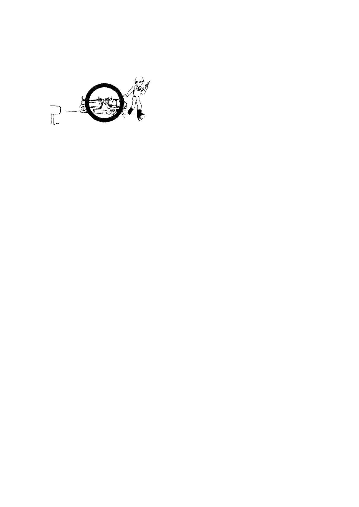
·When parking the machine, park it in a safe
place outside the working area, or the
specified place. The following factors should
be considered when choosing a parking place:
it should be on flat, firm ground where there
is no danger of rock-fall, landslides or floods.
If the machine has to be parked on a slope,
PARKING
it should be parked facing directly up or down the slope, and chocks should be placed under
the tires. When the machine is facing downhill, lower the blade so that it cuts slightly into the
ground to further increase the safety.
·When parking the machine, return the gear shift lever to “NEUTRAL”, apply the brake lock,
lower the blade, scarifier and ripper to the ground, and put all safety levers in the “LOCK”
position. Switch off the engine and remove the key.
10- 91
Page 92
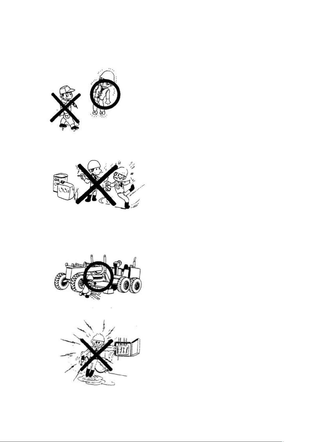
·Wear proper clothes
Loose clothes, ornaments or other things that
may possible contact the control lever or
other machine parts must not be worn.
Do not let you clothes get caught on
protruding parts of the machine. Do not oily
clothes since they may catch fire.
Wear well-fitting helmet, safety shoes and
·Fuel or oil are dangerous substances. Never
handle fuel, oil, grease or oily clothes in
places where there is any fire or flame. As
preparation in case of fire, always know the
location and directions for use of fire
extinguishers and other fire-fighting
equipment.
·Always stop the engine before cleaning the
machine or adding fuel.
·When working with others, choose a group
leader and work according to his instructions.
Do not perform any maintenance beyond the
agreed work.
·Do not handle electrical equipment while
wearing wet gloves, or in wet places, as this
can cause electric shock.
· During maintenance, do not allow any
unauthorized person to stand near the
machine.
PRECAUTION FOR MAINTENANCE
GENERAL
working clothes. When drilling, grinding or hammering, always wear protective goggles.
10- 92
Page 93
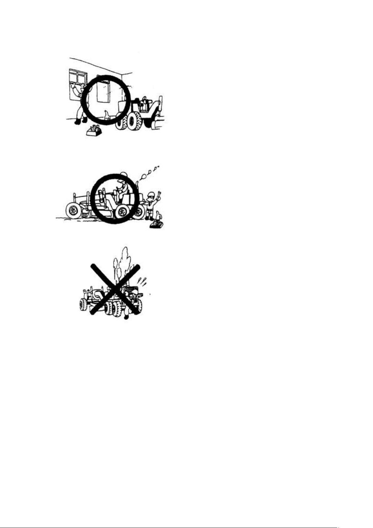
·Exhaust gas is dangerous. When working
inside, be particularly careful to have good
ventilation.
·Unless you have special instructions to the
contrary, maintenance should always be
carried out with the engine stopping. If
maintenance is carried out with the engine
running, there must be two men present: one
sitting in the operator´s seat and the other one
performing the maintenance. In such a case,
never touch any moving part.
·Always remember that the hydraulic oil
circuit is under pressure. When feeding or
draining the oil or carrying out inspection and
maintenance, release the pressure first. The
procedure for releasing the hydraulic pressure
is as follows: lower the blade, scarifier and
ripper to the ground, and stop the engine,
Move the control levers to each position two or three times and then slowly loosen the oil
filler cap.
·Always use POWERTRAC genuine parts for replacement.
·Always use the grades and oil recommended by POWERTRAC. Choose the viscosity
specified for the ambient temperature.
·Always use pure oil or grease, and be sure to use clean containers.
·When checking or changing the oil, do it in a place free of dust, and prevent any dirt from
getting into the oil.
10- 93
Page 94
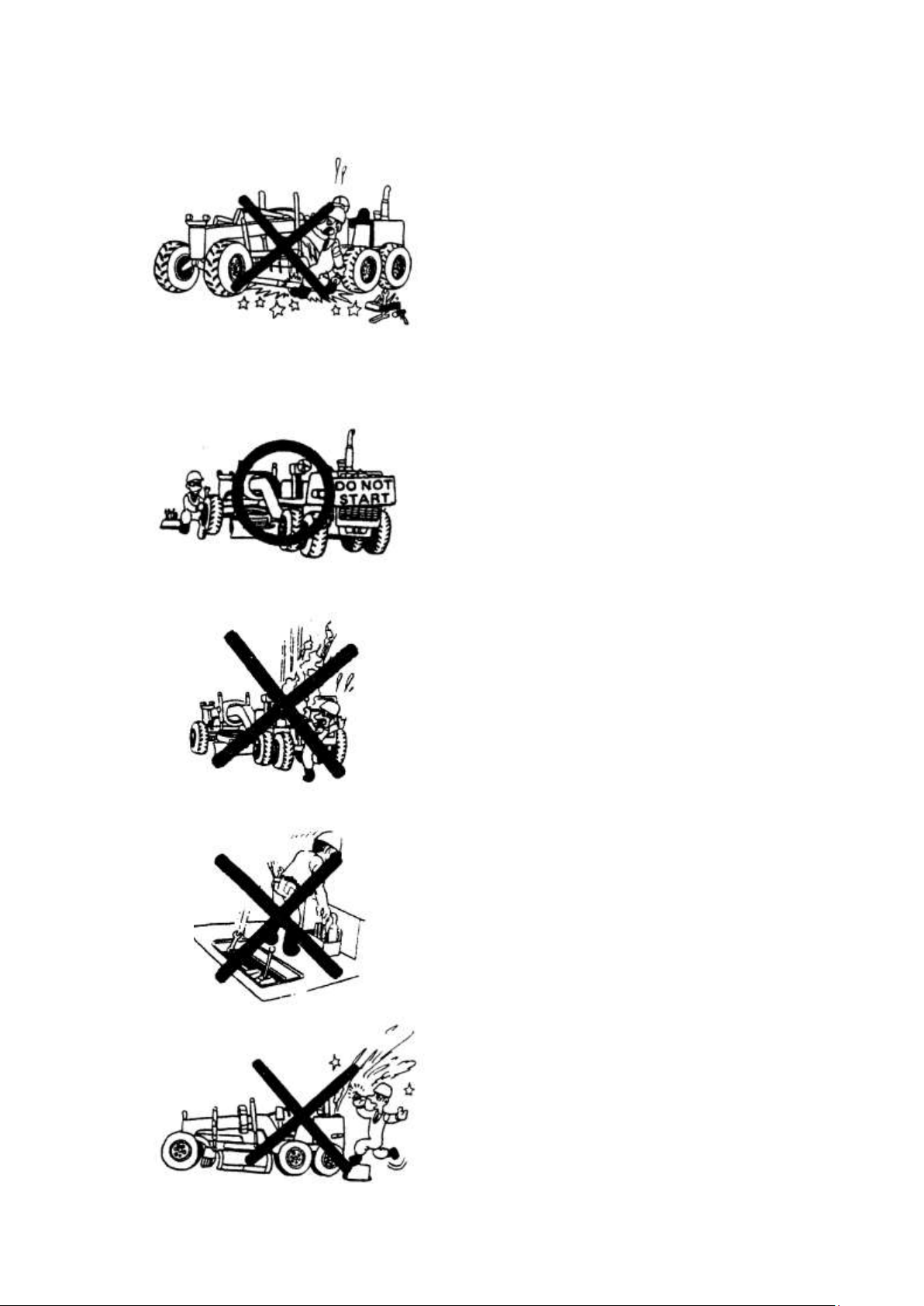
·Park the machine on firm, flat ground. Lower the
blade, scarifier and ripper to the ground and stop the
engine. Return the gearshift lever to “NEUTRAL”
position, apply the brake lock and set each control
lever to “LOCK”. When maintenance has to be
carried out with the blade, scarifier and ripper
raised, they must be securely supported by blocks.
·Hang a caution sign in the operator´s compartment
(for example “Do not start” or “Maintenance in
progress”). This will prevent anyone from starting
or moving the machine by mistake.
·Flame should never be used instead of lamps.
Never use a naked flame to check leaks or the level
of oil, fuel, anti-freeze or electrolyte.
·Immediately remove any oil or grease on the floor
of the operator´s compartment, or on the handrail. It
is very dangerous if someone slips while on the
machine.
·When check an open gear case there is a risk
of dropping things in. Before removing the
covers to inspect such cases, empty
everything from your pockets. Be particularly
careful to remove wrenches and nuts.
·Before draining the oil, warm up it to a
temperature of 20 to 40℃
·Be particularly careful when removing the radiator
cap or the hydraulic oil tank filler cap. If this is done
immediately after using the machine, there is a
danger that boiling water or oil may spurt out.
DURING MAINTENANCE
·Thoroughly wash the machine. In particular, be careful to clean the filler caps grease fittings
and the area around the dip sticks. Be careful not to let any dirt or dust into the system.
10- 94
Page 95
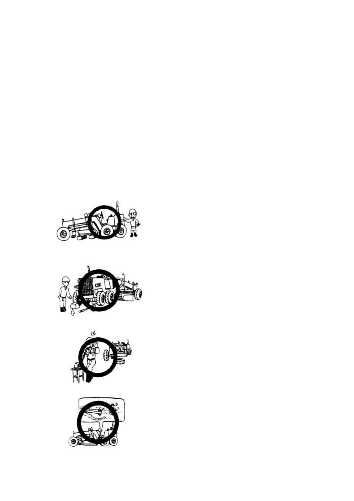
·When the work equipment is raised for inspection or
repair, always place blocks underneath to prevent
falling.
·When the machine is jacked up, always put chocks
against the wheels on the opposite side. After jack up,
place blocks prevent the machine from falling.
·Disassembly, repair and assembly of tires require
special equipment and high skill. Always consult a
specialized tire repair shop.
·Always lock the front and rear frames before
inspecting and servicing the machine.
·After replacing oil, filter element or strainer , bleed the air from the circuit.
·When the strainer is located in the oil filler, the strainer must not be removed while adding
oil.
·When adding oil or checking the oil level, check that the oil at the correct level.
When adding oil or fuel, do not let the oil or fuel overflow.
·If oil or water are spilled, always wipe it up. Spilled oil or water may cause people to slip
and the spilled oil may cause fire.
If oil is piled on top of a place where fuel has been spilled, remove the oil.
·After greasing up, always wipe off the old grease that was forced out.
·When changing the oil or filter, check the drained oil and filler for any signs of excessive
metal particles or other foreign materials.
·When removing parts containing 0-rings, gaskets or seals, clean the mounting surface and
replace with new sealing parts.
10- 95
Page 96
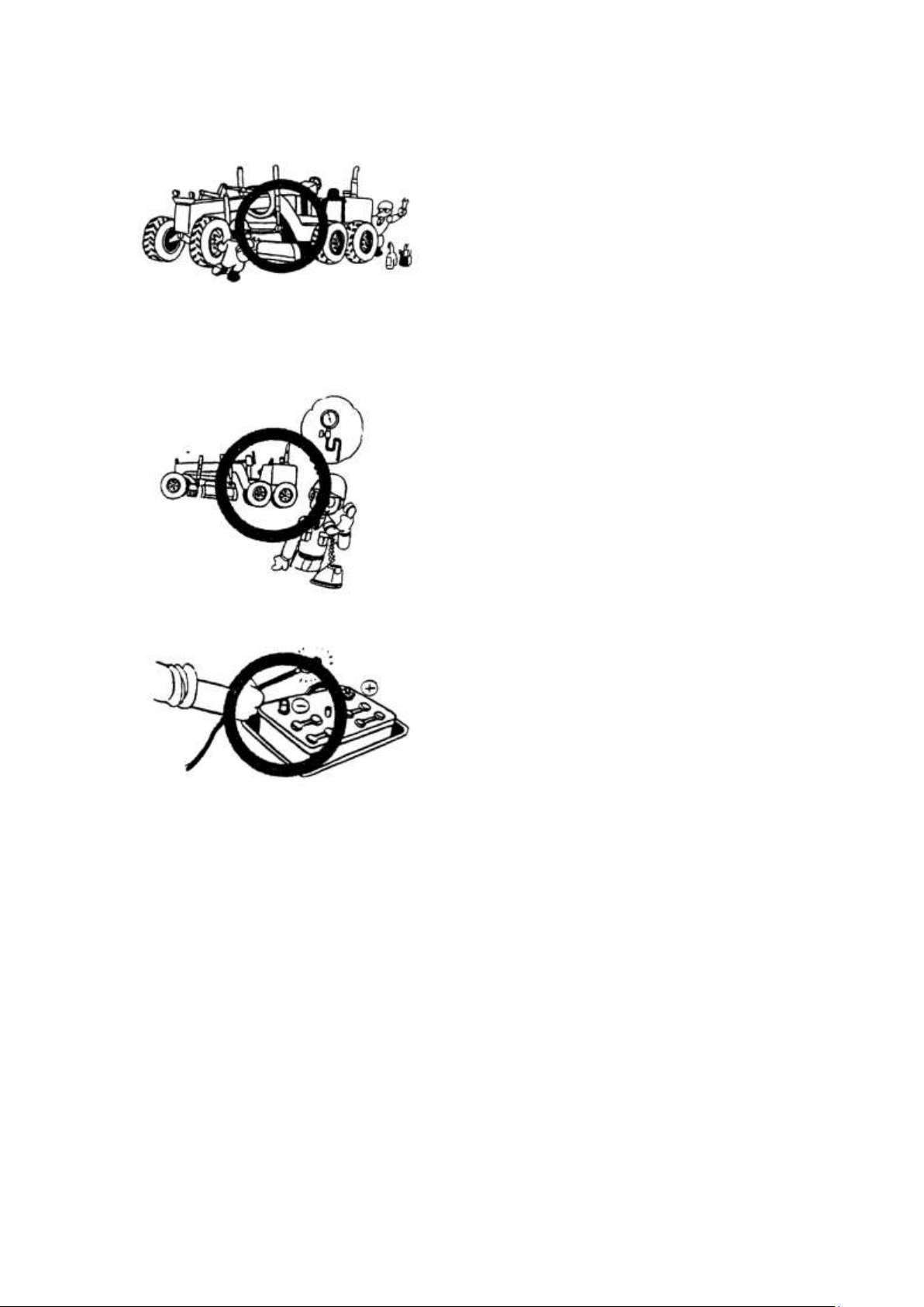
·Put the glove when use the wrench to
maintain the cutting blade.
·Special measuring apparatus is needed for
testing hydraulic pressure.
·Remove the minus terminal from the battery
in maintaining the electrical system.
· When carrying out other difficult
maintenance work, carrying them out
carelessly can cause unexpected accidents. If
you consider the maintenance is too difficult,
always request the POWERTRAC distributor
to carry it out.
10- 96
Page 97

HANDLING OF BATTERY
PRECAUTIONS FOR CHARGING BATTERY
▲Before starting the engine, use a damp cloth to wipe off the dust accumulated on the top
surface of the battery.
1. Before charging, disconnect the cable from the negative (-) terminal of the battery;
otherwise, an abnormal high voltage will damage the alternator.
2. While charging the battery, remove all battery plugs for satisfactory ventilation. To
avoid gas explosions, do not bring fire or sparks near the battery.
3. If the electrolyte temperature exceeds 45℃, stop charging for awhile.
4. Turn off the charger as soon as the battery is charged.
Over charging the battery may cause followings:
1) Overheating the battery
2) Decreasing the quantity of electrolyte
3) Damaging the electrode plate
5. If the electrolyte gets on your skin or clothes, immediately wash plenty of clean water.
6. Do not mix up cables positive (+) to negative (-) or negative (-) to positive (+), as it
will damage the alternator.
7. When inspecting or servicing a battery, be sure to stop the engine and turn the starting
switch key to “OFF” position.
8. When performing or service to battery besides checking the electrolyte level or
measuring the specific gravity, disconnect cables from the battery.
REMOVAL AND INSTALLATION OF BATTERY
·When removing battery, first disconnect the cable from the ground (normally, from the
negative (-) terminal). If a tool touches a cable connecting the positive terminal and the
chassis, there is danger of sparks being emitted.
·When installing battery, the ground cable is connected to the ground terminal as the last step.
STARTING ENGINE WITH A BOOSTER CABLE
When starting up engine with a booster cable, do as follows:
1. Before connecting the booster cable
i. Size of booster cable and clip should be suitable for the battery size.
ii. Check cables and clips for breakage and corroded surfaces, etc.
iii. Make sure cables and clips are firmly secured.
iv. Keep the starting switch key in OFF position.
v. The battery of the running engine must be the same capacity as that of engine to
be started.
2. Connect the booster cables in the following manner:
1) Connect one clip of booster cable A to the positive (+) terminal of the engine to be
started.
2) Connect the other clip to the positive (+) terminal of the engine which is running.
3) Connect one clip of booster cable B to the positive (-) terminal of the engine which is
running.
4) Connect the other clip to the body of the machine to be started.
10- 97
Page 98
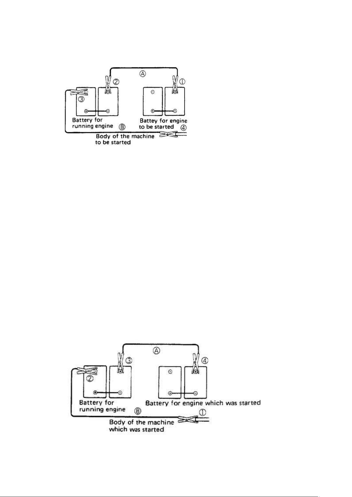
Make sure the clips are firmly connected to battery terminal. Then, start the engine.
When connecting the cables, never connect the positive (+) and the negative (-) terminals.
Make sure that the booster cable connections are correct. Connect the booster cable to the
body as far as possible from the battery.
3. Starting the engine
1) Turn the starting switch key to START position and start up the engine.
2) If the engine doesn´t start at first, try again after 2 minutes or so.
After the engine has started, the booster cables should be disconnected in the reverse order
in which they were connected.
Disconnecting the booster cables
(1) Disconnecting the clip of booster cable B from the body of the machine which was
started.
(2) Disconnecting the other clip from the negative (-) terminal of the running engine.
(3) Disconnecting the clip of booster cable A from the positive (+) terminal of the running
engine.
(4) Disconnecting the other clip from the positive (+) terminal of the engine which was
started.
10- 98
Page 99
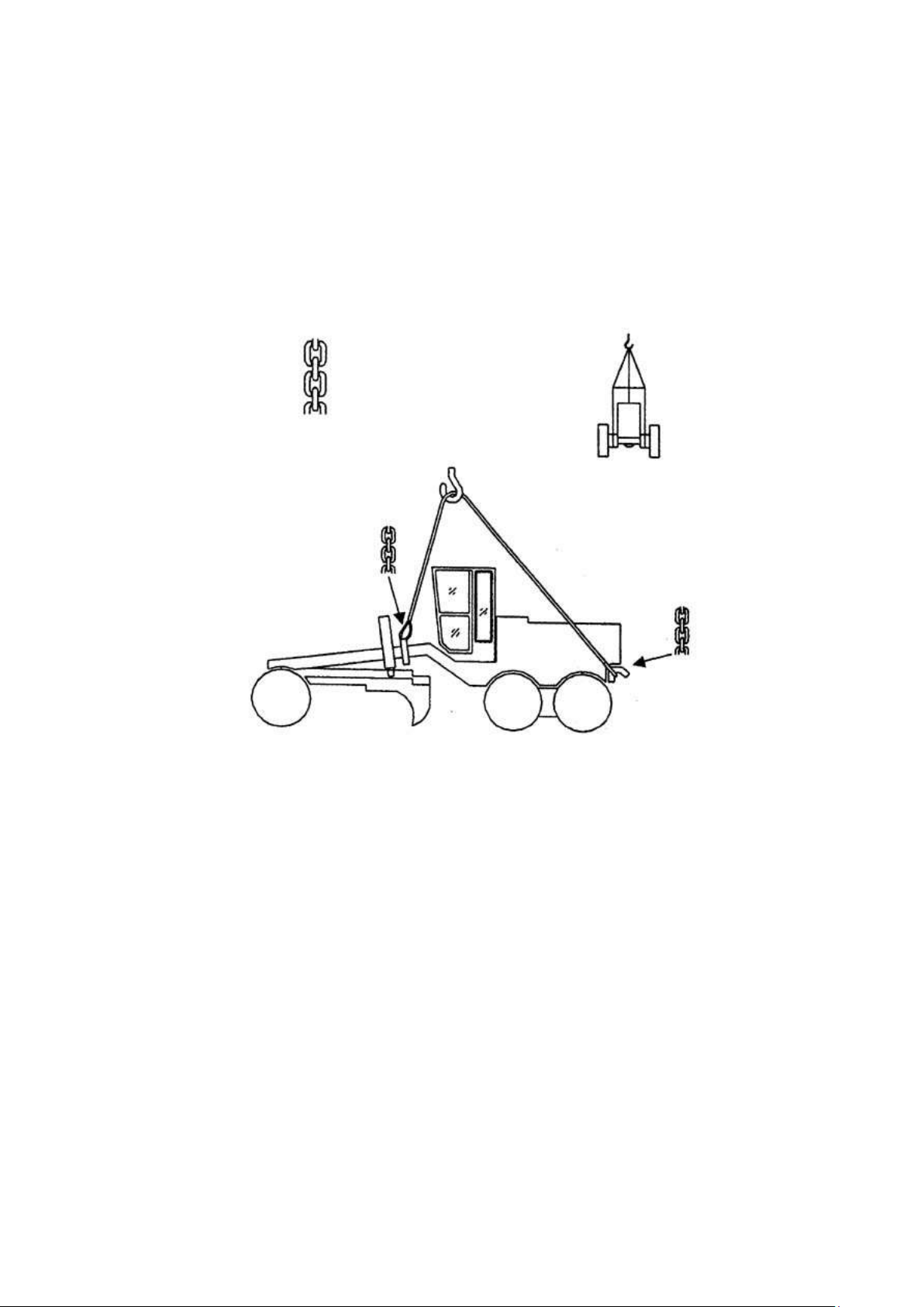
HANGING UP
When need to hang up the machine in special case, the articulation lock pin between the front
and rear frames should be locked first. Then, use a wire rope to pass through the hang ring on
the machine body shown in the below figure, and hang up the machine according to the mark
requirement on the tail of the machine.
10- 99
Page 100

TRANSPORTATION
In addition to strict observance of traffic laws and rules concerned, it is desirable to provide a
special platform for loading and unloading of the motor grader, if it is necessary to use a ramp
when loading a motor grader on a trailer or unloading it from a trailer, observe the following
instructions to assure safety:
1. Securely brake the trailer and chock trailer tires. Securely fix the ramp boards in place so
that the center of motor grader being loaded coincides with the centerline of the trailer.
★Width, length and thickness of ramp boards must large enough to assure safe loading and
unloading of the motor grader.
▲Remove the mud form the undercarriage to prevent the machine form slipping to the side
on slopes.
2. Slowly travel the motor grader on the ramp straight.
▲Never attempt to change the direction of travel on the ramp. If it is necessary to change the
direction of travel, once return the machine to the original position.
3. Properly load the motor grade on the trailer at the specified position. To prevent the grader
on the trailer from moving back and forth during transportation, apply a chock to front and
rear of each wheel and fix the motor grader with chains and wire ropes. Pay special care to
prevent the grader from slipping sideward.
4. Rest the work equipment on the trailer deck and observe the following:
·Pull the parking brake lever.
·Place the gearshift lever in the neutral position.
·Place work equipment control lever in hold position.
·Apply safety locks.
·Pull the starting switch key out.
★Determine the optimum transportation route, taking width of road and permissible overhead
clearance and weight limitation into consideration.
★Lock the articulation lock pin in the same way as for normal travel.
▲Do not leave the front wheels raised off the trailer deck using the brake as a jack. The front
wheels will fall gradually during transportation.
▲When loading the machine, choose a firm level road surface. Be sure that you are well clear
of the road shoulder.
★When transporting this machine, check with your POWERTRAC distributor for advice.
10- 100
 Loading...