

Page 1
1
POWERTEX Chain Block model PCB-S1
UMPCBB20181119LT
!
GB Instruconforuse
LT Naudojimoinstrukcija
Page 2

2
POWERTEX Chain Block PCB-S1 0.25 – 20 tonnes
Instruction for use (GB) (Original instructions)
Read through these user instructions carefully before using the chain block. Improper operation may lead to hazardous situations!
General safety provisions
• Check the function of the chain block before use. See “Daily checks” on page 3.
• Full function of the brake system can only be secured at a minimum load of 30 kg for capacities (WLL) up to 1 ton,
and for capacities (WLL) above 1 ton, the minimum load to be greater than 3% of the rated capacity (WLL).
• Do not exceed the maximum load.
• Handle the chain block with care. Do not throw the block about or let it fall to the ground.
• Do not use the chain block for welding work where it is exposed to welding spatter or current.
• The chain block must not be used for lifting persons.
Technical data
Safety factor : 4:1.
Static test coefcient: WLL x 1,5.
Generally according to EN 13157.
Function
The load hook is raised or lowered by pulling on the hand chain. The load will remain where it is even when the hand chain is released because
of the effective reaction brake.
Suspension of chain block
Suspend the block from an eye, shackle, girder trolley etc. with sufcient load capacity. With the chain tightened, both hooks must be vertically
aligned.
NB! No bending stresses may be applied to block, hooks or load chain.
Raising/lowering
Only use straps and slings of sufcient load capacity. Check that the load is not anchored to the oor/ground or is otherwise xed before making
the lift. Ensure that the load chain hangs vertically and has no kinks. The hand chain must also be in good condition and easily accessible. The
load is raised or lowered by pulling the hand chain in either direction.
Warning:
• Only hand power from a single person is permitted on the hand chain. If the chain feels too heavy, use a bigger chain block or reduce the
load.
• Make sure no-one stands beneath a hanging load.
• Do not step onto a hanging load.
• Do not raise or lower so far that the load hook hits the block housing.
• The chain block must not be used for pulling loads.
• The block must not be subjected to dynamic stresses, for example where a load connected to the block is launched from a height.
• Do not leave a block with a suspended load unattended.
Model PCB-S1 PCB-S1 PCB-S1 PCB-S1 PCB-S1 PCB-S1 PCB-S1 PCB-S1
Max. Load tonnes 0,25 0,5 1 2 3 5 10 20
Standard lifting height *) m 3 3 3 3 3 3 3 3
Number of block falls 1 1 1 1 1 2 3 8
Pull on hand chain daN (kp) 19 21 29 36 41 40 46 2x40
Load chain 4x12 5x15 6,3x19 8x24 10x30 9x27 10x30 9x27
Dimension A mm 106 128 142 175 195 183 195 183
Dimension B mm 68 75 76 88 95 90 95 90
Dimension C mm 108 130 150 185 226 255 355 577
Dimension Ø mm 18 20 25 33 36 43 44 110
Dimension E mm 20 22 26 35 37 44 47 70
Dimension H min mm 280 330 360 470 560 690 810 1.060
Weight for standard lift height kg 6,4 8,9 12 19,5 29,4 36,6 64,1 185
*) Length of hand chain varies according to lifting height.
Page 3
3
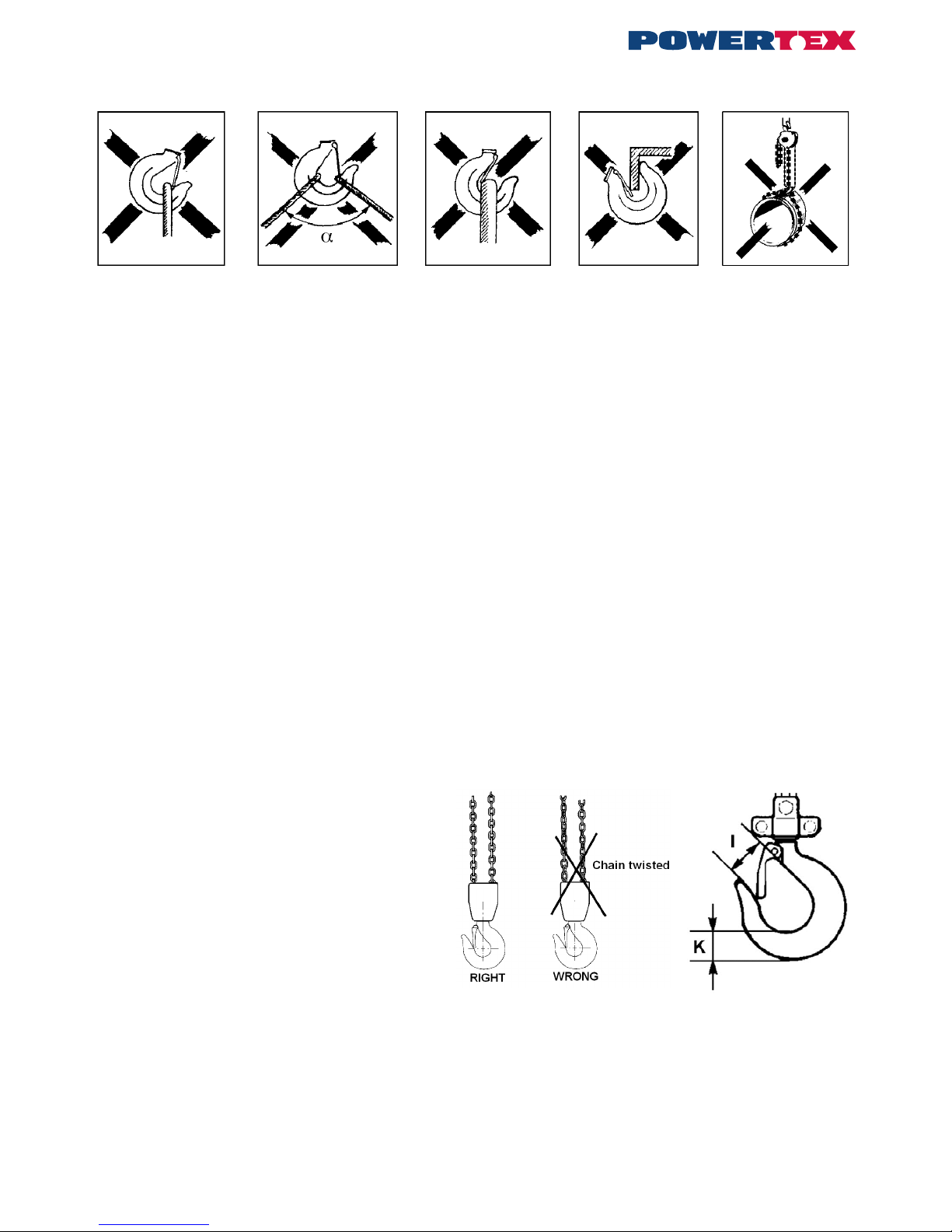
Attachment of loads
Check the equipment before use. Improper attachment of loads can be highly dangerous (see Figs. 2 a – 2 e).
Fig 2 a
The sling is applying
load to the hook tip
Fig 2 b
Excessive top angle
on sling!
α max 60°
Fig 2 c
Hook latch
obstructed
Fig 2 d
Hook tip
subject to additional
bending stress
Fig 2 e
Load chain must not
be used as a sling
Multiple lifting
Multiple lifting presents special risks. This is when two or perhaps more hoists are used simultaneously for the same load. Danger to persons and
material damage can arise due to dynamic stresses and uneven load distribution causing individual hoists to become overloaded. A competent
person with experience in multiple lifting must therefore supervise this type of lifting tasks.
The total weight of the target object and its load distribution must be known or calculated.
For a variety of reasons, the centre of gravity can be difcult to determine, and thus so will the distribution of the load each hoist must bear. In
cases where heavy, bulky loads must be handled and it is not possible to estimate all factors correctly, the max working load limit (WLL) of each
hoist must be reduced by at least 25%.
Daily checks
After every working day on which the chain block has been used, the following should be checked:
• Is the chain block deformed or otherwise damaged? Are any parts missing?
• Is any deformation or other damage visible on the suspension device (eye, shackle, bolt, trolley etc.)?
• Are the hooks intact or have any hooks opened? Are the hook latches correct and functional?
• Wipe down the chain block and oil the load chain as required.
• The load chain must be undamaged, i.e. no signs of wear and no deformed or otherwise damaged links.
• The load chain must not be kinked or twisted. With two-fall or multi-fall chain blocks there is a risk of the chain twisting if the bottom hook
assembly ends up looped through the chain sling – usually during retting or moving the chain block between work stations. See Fig 3.
• The hand chain must also be in good condition.
• The brake function must be intact.
In the event of faults or failures, the block must be repaired and carefully checked by a specialist before reuse.
Continuous maintenance - lubrication
Oil the hook latches and bearings. Grease the pawl and ratchet and also the gear. Lubrication must be sparingly and carefully applied so no grease gets on the brake disk. Oil the load chain for longer life.
Periodic checks
Periodic checks are normally carried out yearly to detect and remedy any faults. If required (e.g. high frequency of use), more frequent checks
may be carried out. See “Checklist for periodic checks”. Measure hooks and chain to detect any changes in shape.
Checks on load hook (see Fig. 4 and Table 1)
Opening dimension l on the hooks is important. A hook with too
large a maximum dimension has been exposed to overloading
or overheating. It therefore does not have the necessary load
capacity. The hooks may also have been exposed to long-term
wear (dimension K).
Hooks must be discarded and replaced if:
• The maximum l value is exceeded (according to Table 1)
• The minimum K value falls short (according to Table 1)
• The hook shows signs of cracking
• The hook is deformed or otherwise damaged
Defective hooks must be replaced before using the chain block
again.
Fig. 3 The chain must not be twisted Fig. 4 Load hook
Page 4

4
Table 1 Load hook
Max. load t 0,25 0,5 1 2 3 5 10 20
Model PCB-S1 PCB-S1 PCB-S1 PCB-S1 PCB-S1 PCB-S1 PCB-S1 PCB-S1
Dimension I nominal mm 24 25,5 30 38,5 41,5 47 55 84
Dimension I max mm 26,4 28,0 33 42,3 45,5 51,7 60,5 92,4
Dimension K nominal mm 15 19 25 33,5 39 44,5 62 93
Dimension K min mm 13,5 17,1 22,5 30,2 35,1 40,0 55,8 83,7
Checks on load chain (see Fig. 5 and Table 2)
Inspect the load chain over its whole length to detect any deformed or otherwise damaged links. Make a check measurement of suspect links.
Measure the worn areas Also, every 300 mm (normally), make check measurements of the internal length of 5 links (pitch dimension 5xP – according to Table 2).
Fig 5 Checking chain dimensions
Table 2 Load chain
Max. load t 0,25 0,5 1 2 3 5 10 20
Model PCB-S1 PCB-S1 PCB-S1 PCB-S1 PCB-S1 PCB-S1 PCB-S1 PCB-S1
Link diameter nominal mm 4,0 5,0 6,3 8,0 10,0 9,0 10,0 9,0
Link diameter min. mm 3,6 4,5 5,7 7,2 9,0 8,1 9,0 8,1
Pitch dimension (5xP) nominal mm 60,0 75,0 95,0 120,0 150,0 135,0 150,0 135,0
Pitch dimension (5xP) max. mm 61,8 77,2 98,0 123,5 154,5 139,0 154,5 139,0
The load chain must be discarded and replaced if:
• cracks are detected on any link
• any link is deformed or otherwise damaged
• The minimum value of any link’s diameter falls short
• the maximum value of the pitch dimension is exceeded at any point
• the chain is damaged by overheating or has been affected by weld splatter
Load chains must not be repaired – they must be replaced by new chain. If it is desired to lengthen the chain, it must be replaced by a new and
longer chain.
Replacement of the chain shall be performed professionally by an authorized repairer and the chain must meet the requirements stated in the
standard EN 818-7 from the following manufacturers: Chaineries Limousines, Pewag, Thiele or Rud
Repairs
The chain block must not be modied. Repairs must be carried out by specialists. Damaged parts must only be replaced with original Powertex
spare parts. Order them through your dealer.
Page 5

5
Checklist for periodic checks (normally yearly – more frequently if necessary)
Daily Yearly Inspection items Inspection method Note
Labels
X X Rating plate Visual If the plate is hard to read - replace it
Function
X X Raising and lowering function Test without load A low snapping noise should be audible
- X Raising and lowering function Test with rated weight
for min 300 mm
Load chain sprocket and chain work well together.
Brake works.
Hand pulling on the hand chain feels even and
not too heavy
Hooks
X
-
X Hook opening Visual
Measurements
Looks normal
See Fig. 4 and Table 1
X X Deformation Visual No visibel deformation
X Hook bearing Visual No abnormal play
X
-
X Wear, cracks, deformation and corrosion Visual
Measurements
No visible damage
See Fig. 4 and Table 1
X Hook bearing Visual No abnormal play
Load chain
X
-
X Pitch Visual
Measurement
Looks normal. Measure in case of doubt
See Fig. 5 and Table 2
X
-
X Wear Visual
Measurement
Looks problem-free.
Measure in case of doubt
See Fig. 5 and Table 2
X X Deformation Visual No deformation. Measure in case of doubt
X X Cracks etc. Visual No cracks
X X Rust Visual No rust
Housing
X X Frame Visual No deformation and no rust
X X Gearbox Visual No deformation
- X Gears Visual after dismantling No serious wear or fractures
- X Load chain sprocket Visual after dismantling No serious wear or cracks.
No fractures or deformation
- X Hand chain sprocket Visual No serious wear or cracks.
No fractures or deformation
- X Bearings Visual, testing No damage, smooth running
Screws
X Screws, nuts, rivets, cotters etc. Visual Must not be missing. Tighten loose items.
Replace as necessary
Brake
- X Brake disk Visual Replace if worn
- X Brake screw Visual No serious wear
- X Pawl and ratchet Visual Replace worn parts.
Carefully lubricate with grease
Page 6

6
POWERTEX kabinama grandininė PCB-S1 0.25 – 20 tonos
Naudojimo instrukcija (LT)
Prieš pradėdami naudoti grandininę gervę, įdėmiai perskaitykite šią naudojimo instrukciją. Dėl netinkamo prietaiso naudojimo padidėja nelaimingų
atsitikimų rizika!
Bendrieji saugumo nuostatai
• Prieš pradėdami naudoti patikrinkite grandininės gervės funkcijas. Skaitykite p. 7 esantį skyrelį „Kasdienė patikra“.
• Neviršykite leistinos maksimalios apkrovos.
• Visiškas stabdžių sistemos funkcionavimas gali būti užtikrintas tik esant minimaliai 30 kg apkrovai, kai galia (WLL) yra iki 1 tonos; kai galia
(WLL) yra didesnė nei 1 tona, minimali apkrova turi sudaryti daugiau nei 3 proc. vardinės galios (WLL).
• Dirbdami su grandinine gerve būkite atsargūs. Nenumeskite keltuvo ir saugokite, kad jis nenukristų ant žemės.
• Nenaudokite grandininės gervės suvirinimo darbams, nes ją gali pažeisti suvirinimo metu išsiskiriantys tiškalai ar elektros srovė.
• Gervė nenaudotina žmonėms kelti.
Techniniai duomenys
Saugumo veiksnys: 4:1.
Statinis bandymo koecientas: WLL x 1,5.
Bendrai pagal EN 13157.
Funkcijos
Krovinys pakeliamas arba nuleidžiamas traukiant rankinę grandinę. Dėl efektyviai veikiančio stabdžio krovinys sulaikomas net ir atleidus rankinę
grandinę.
Grandininės gervės kabėjimas
Pakabinkite gervę ant tvirtinimo žiedo, apkabos, sijos vežimėlio ar kt. įtaiso, galinčio atlaikyti atitinkamą apkrovą. Grandinei esant įtemptai, abu
kabliai turi būti išdėstyti vertikalia linija.
Dėmesio! Vengti gervės, kablių ir grandinės lenkimo įtempio.
Pakėlimas/nuleidimas
Naudokite tik tinkamo stiprumo juostas ir virves. Prieš keldami krovinį, įsitikinkite, ar jis nėra pritvirtintas prie žemės/grindų ar kitaip užksuotas.
Patikrinkite, ar krovinio grandinė kabo vertikaliai ir nėra susiraizgiusi. Rankinė grandinė taip pat turi būti tinkamos būklės ir lengvai pasiekiama.
Krovinys pakeliamas arba nuleidžiamas traukiant rankinę grandinę bet kuria kryptimi.
Įspėjimai
• Grandinė gali būti tempiama tik vieno asmens rankų jėga. Jei grandinę tempti per sunku, naudokite didesnę grandininę gervę arba su-
mažinkite krovinį.
• Patikrinkite, ar joks asmuo nestovi po kabančiu kroviniu.
• Neužminkite ant kabančio krovinio.
• Kelkite ir nuleiskite gervę su kroviniu taip, kad krovinio kablys nesiektų gervės korpuso.
• Gervė nenaudotina kroviniams traukti.
• Gervė negali būti veikiama dinaminės apkrovos, pvz., kai krovinys, pritvirtintas prie gervės, yra leidžiamas iš viršaus.
• Nepalikite gervės su kabančiu kroviniu be priežiūros.
Modelis PCB-S1 PCB-S1 PCB-S1 PCB-S1 PCB-S1 PCB-S1 PCB-S1 PCB-S1
Maksimali apkrova tonos 0,25 0,5 1 2 3 5 10 20
Standartinis kėlimo aukštis *) m 3 3 3 3 3 3 3 3
Lynų skaičius 1 1 1 1 1 2 3 8
Grandinę veikianti jėga daN (kp) 19 21 29 36 41 40 46 2x40
Load chain 4x12 5x15 6,3x19 8x24 10x30 9x27 10x30 9x27
A dydis, mm 106 128 142 175 195 183 195 183
B dydis, mm 68 75 76 88 95 90 95 90
C dydis, mm 108 130 150 185 226 255 355 577
Ø dydis, mm 18 20 25 33 36 43 44 110
E dydis, mm 20 22 26 35 37 44 47 70
H dydis (min.), mm 280 330 360 470 560 690 810 1.060
Svoris keliant į standartinį aukštį kg 6,4 8,9 12 19,5 29,4 36,6 64,1 185
*) Rankinės grandinės ilgis priklauso nuo kėlimo aukščio.
Page 7

7
Krovinių tvirtinimas
Prieš naudodami patikrinkite įrangą. Netinkamai pritvirtinti kroviniai gali būti labai pavojingi (žr. pav. 2a–e).
Kėlimas naudojant kelis keltuvus
Kėlimas naudojant kelis keltuvus yra susijęs su tam tikru pavojumi. Jis kyla, kai tam pačiam kroviniui pakelti vienu metu naudojami du arba daugiau keltuvų. Pavojus susižaloti žmonėms arba sugadinti turtą gali kilti dėl dinaminių įtempių ir nevienodai
paskirstytos apkrovos, dėl kurios pernelyg apkraunami atskiri keltuvai. T
odėl šio tipo kėlimo užduotis turi prižiūrėti kompetentingas
asmuo, turintis kėlimo naudojant kelis keltuvus darbo patirties.
Būtina žinoti arba apskaičiuoti bendrąjį keliamo objekto svorį ir jo apkrovos pasiskirstymą.
Dėl daugybės priežasčių gali būti sunku nustatyti sunkio centrą bei apkrovos, kurią turi atlaikyti kiekvienas keltuvas, pasiskirstymą. Tais atvejais, kai reikia kelti sunkius, didelius krovinius ir neįmanoma tinkamai įvertinti visų veiksnių, maksimali ribinė
darbinė kiekvieno keltuvo apkrova turi būti sumažinta bent 25%.
Kasdienė patikra
Kasdien baigus darbą su gerve, turi būti patikrinti šie punktai:
• Ar grandininė gervė nebuvo deformuota ar kitaip pažeista? Ar netrūksta kokių nors gervės dalių?
• Ar ant kabinimo įtaiso (tvirtinimo žiedo, apkabos, varžto, vežimėlio ir pan.) nematyti kokių nors deformacijos žymių ar kitų pažeidimų?
• Ar nepažeisti bei neatidaryti kabliai? Ar nepažeisti ir tinkamai veikia kablio ksatoriai?
• Nušluostykite grandininę gervę ir sutepkite krovinio grandinę, kaip reikalaujama.
• Naudojama krovinio grandinė negali būti pažeista, t. y. neturi būti jokių nusidėvėjimo ženklų, jokių deformuotų ir kitaip pažeistų grandžių.
• Krovinio grandinė negali būti susisukusi ar susinarpliojusi. Naudojant dviejų ar daugiau lynų turinčią grandininę gervę, grandinė gali susinar-
plioti, jei apatinio kablio įtaisas susipainios su grandinės kilpa – paprastai taip nutinka iš naujo montuojant visą įrenginį arba perkeliant grandininę gervę iš vienos darbo vietos į kitą. Žr. pav. 3.
• Rankinė grandinė taip pat turi būti geros būklės.
• Turi tinkamai veikti stabdymo funkcija.
Aptikus gedimą ar sutrikimą, keltuvą reikia kruopščiai patikrinti ir perduoti taisyti specialistui.
Nuolatinė priežiūra – tepimas
Sutepkite kablio ksatorius ir guolius. Taip pat sutepkite strektę, reketą bei pavaras. Tepti reikia atsargiai. Negalima naudoti per daug tepalo, kad
jo nepatektų ant stabdžio disko. Jei norite, kad grandinė ilgiau tarnautų, sutepkite ją.
Reguliari patikra
Reguliari patikra paprastai atliekama kasmet, siekiant nustatyti ir pašalinti bet kokius gedimus. Jei reikia (pvz., įrenginį dažnai naudojant), patikra
gali būti atliekama dažniau. Žr. „Reguliarios patikros lapas“. Išmatuokite kablius ir grandinę, patikrindami, ar nepakitusios jų formos.
Krovinio kablio patikra (žr. pav. 4 ir lent. 1)
Labai svarbus kablio angos l dydis. Šią ribinę maksimalią reikšmę
viršijantis kablys buvo paveiktas perkrovos ar perkaitimo. Todėl
jis negali atlaikyti reikiamos apkrovos. Kablys taip pat gali ilgainiui
nusidėvėti (K dydis).
Kablį reikia išmesti ir pakeisti nauju, jei:
• viršijamas maksimalus l dydis (pagal lent. 1);
• nesiekiamas minimalus K dydis (pagal lent. 1);
• yra įtrūkimo žymių;
• kablys buvo deformuotas ar kitaip pažeistas.
Sugadinti kabliai turi būti pakeisti prieš naudojant grandininę gervę.
pav. 3. Grandinė neturi būti susisukusi. pav. 4. Krovinio kablys
Rätt Fel
Susinarpliojo grandiné
Teisingai Neteisingai
pav. 2a.
Virvės kilpa yra prie
kablio galo.
pav. 2b.
Per didelis virvės
kilpos kampas!
α max 60°.
pav. 2c.
Užstotas kablio
ksatorius.
pav. 2d.
Kablio galas veikiamas
papildomo lenkimo įtempio.
pav. 2e.
Krovinio grandinė
negali būti naudojama
kaip virvė.
Page 8

8
Lent. 1. Krovinio kablys
Maks. apkrova. tonos 0,25 0,5 1 2 3 5 10 20
Modelis PCB-S1 PCB-S1 PCB-S1 PCB-S1 PCB-S1 PCB-S1 PCB-S1 PCB-S1
Nominalus I dydis, mm 24 25,5 30 38,5 41,5 47 55 84
Maks. I dydis, mm 26,4 28,0 33 42,3 45,5 51,7 60,5 92,4
Nominalus K dydis, mm 15 19 25 33,5 39 44,5 62 93
Min. K dydis, mm 13,5 17,1 22,5 30,2 35,1 40,0 55,8 83,7
Krovinio grandinės patikra (žr. pav. 5 ir lent. 2)
Apžiūrėkite krovinio grandinę per visą ilgį, patikrindami, ar nėra deformuotų ar kitaip pažeistų grandžių. Išmatuokite įtartinas grandis. Išmatuokite
ir susidėvėjusias vietas. Kas 300 mm (normaliomis sąlygomis) išmatuokite penkių grandžių vidinį ilgį (pagal lent. 2 – dydis 5xP).
pav. 5. Grandinės matmenų patikra
Lent. 2. Krovinio grandinė
Maks. apkrova, tonos 0,25 0,5 1 2 3 5 10 20
Modelis PCB-S1 PCB-S1 PCB-S1 PCB-S1 PCB-S1 PCB-S1 PCB-S1 PCB-S1
Nominalus grandies skersmuo, mm 4,0 5,0 6,3 8,0 10,0 9,0 10,0 9,0
Min. grandies skersmuo, mm 3,6 4,5 5,7 7,2 9,0 8,1 9,0 8,1
Nominalus grandies dydis (5xP), mm 60,0 75,0 95,0 120,0 150,0 135,0 150,0 135,0
Maks. grandies dydis (5xP), mm 61,8 77,2 98,0 123,5 154,5 139,0 154,5 139,0
Krovinio grandinę reikia išmesti ir pakeisti nauja, jei:
• ant kurios nors grandies yra įtrūkimų;
• kuri nors grandis buvo deformuota ar kitaip pažeista;
• kurios nors grandies skersmuo nesiekia minimalaus dydžio;
• kuriame nors taške viršijamas maksimalus grandies dydis;
• grandinė buvo pažeista dėl perkaitimo ar virinimo metu išsiskyrusių tiškalų.
Krovinio grandinių NEGALIMA taisyti – jos turi būti pakeistos naujomis. Jei norite pailginti grandinę, senąją reikia pakeisti nauja ilgesne grandine.
Grandinėje atlikti profesionaliai įgaliotųjų remontininkų ir grandinės montavimas turi atitikti reikalavimus, nustatytus standarto EN 818-7 šių ga-
mintojų: Chaineries Limousines, Pewag, Thiele arba Rud.
Remontas
Grandininės gervės negalima modikuoti. Remonto darbus gali atlikti tik specialistai. Pažeistos dalys turi būti keičiamos tik originaliomis Powertex
dalimis. Jas galima užsisakyti per prekybos atstovą.
Page 9

9
Reguliarios patikros lapas (paprastai patikra atliekama kasmet; jei reikia, ją galima atlikti ir dažniau)
Atliekama
kasdien
Atliekama
kasmet
Tikrinimo objektai Tikrinimo metodas Pastabos
Plokštelės
X X Techninių duomenų plokštelė Vizuali patikra Jei plokštelė sunkiai įskaitoma – pakeiskite ją.
Funkcijos
X X Pakėlimo ir nuleidimo funkcija Patikra be krovinio Turi būti girdimas tylus spragtelėjimas
- X Pakėlimo ir nuleidimo funkcija Patikra su nominaliu
svoriu, min. 300 mm
aukštyje
Krovinio grandinės krumpliaratis bei grandinė
kartu veikia gerai. Veikia stabdymo funkcija.
Rankinės grandinės traukimas yra tolygus, traukti
nesunku.
Kabliai
X
-
X Kablio anga Vizuali patikra
Išmatuojama
Atrodo įprastai
Žr. pav. 4 ir lent. 1.
X X Deformacija Vizuali patikra Deformacijos žymių nėra.
X Kablio guolis Vizuali patikra Neįprasto veikimo žymių nėra.
X
-
X Nusidėvėjimas, įtrūkiai, deformacija ir
korozija
Vizuali patikra
Išmatuojama
Pažeidimų nematyti.
Žr. pav. 4 ir lent. 1.
X Kablio guolis Vizuali patikra Neįprasto veikimo požymių nėra.
Krovinio grandinė
X
-
X Matmenys Vizuali patikra
Išmatuojama
Atrodo įprastai. Išmatuokite, jei kyla abejonių.
Žr. pav. 5 ir lent. 2.
X
-
X Nusidėvėjimas Vizuali patikra
Išmatuojama
Atrodo įprastai, nekelia problemų. Išmatuokite, jei
kyla abejonių.
Žr. pav. 5 ir lent. 2.
X X Deformacija Vizuali patikra Deformacijos požymių nėra.
Išmatuokite, jei kyla abejonių.
X X Įtrūkimai ir pan. Vizuali patikra Įtrūkimų nėra.
X X Rūdys Vizuali patikra Rūdžių nėra.
Korpusas
X X Rėmas Vizuali patikra Deformacijos požymių ir rūdžių nėra.
X X Pavarų dėžė Vizuali patikra Deformacijos požymių nėra.
- X Pavaros Vizuali patikra išardžius Rimtų susidėvėjimo žymių ar įtrūkių nėra.
- X Krovinio grandinės krumpliaratis Vizuali patikra išardžius Rimtų susidėvėjimo žymių ar įtrūkių nėra.
Jokių įtrūkių ar deformacijos žymių nėra.
- X Rankinės grandinės krumpliaratis Vizuali patikra Rimtų susidėvėjimo žymių ar įtrūkių nėra.
Jokių įtrūkių ar deformacijos žymių nėra.
- X Guoliai Vizuali patikra Jokių pažeidimų nėra, sklandžiai veikia.
Varžtai
X Varžtai, veržlės, kniedės, vielokaiščiai
ir t. t.
Vizuali patikra Neturi trūkti. Priveržkite atsiveržusias dalis.
Pakeiskite, jei reikia.
Stabdis
- X Stabdžio diskas Vizuali patikra Pakeiskite, jei susidėvėjo.
- X Stabdžio varžtas Vizuali patikra Rimtų susidėvėjimo žymių nėra.
- X Strektė ir reketas Vizuali patikra Pakeiskite susidėvėjusias dalis.
Kruopščiai sutepkite tepalu.
Page 10

10
POWERTEX Chain Block PCB-S1 – Spare parts 0,25 t
When ordering spare parts, specify model, WLL, part number and the quantity needed.
When ordering chain, also specify lifting height.
If the load chain has been damaged or worn out the load sheave probably has to be replaced.
POWERTEX Chain Block 0,25 t
Page 11

11
Pos Description 0,25 t
1 Gear cover assy 16.10PCB1411001
2 Disc gear assy 16.10PCB1411002
3 Drive shaft 16.10PCB1411003
4 Splined gear 16.10PCB1411004
5 Right side plate assy 16.10PCB1411005
6 Load chain sprocket 16.10PCB1411006
9 Top hook shaft 16.10PCB1411009
11 Chain stripper 16.10PCB1411011
13 Guide roller 16.10PCB1411013
14 Left side plate assy 16.10PCB1411014
15 Pawl spring 16.10PCB1411015
16 Pawl 16.10PCB1411016
17 Brake seat 16.10PCB1411017
19 Friction plate 16.10PCB1411019
20 Ratchet wheel 16.10PCB1411020
21 Brake cover 16.10PCB1411021
22 Hand chain wheel 16.10PCB1411022
25 Washer 16.10PCB1411025
26 Hand chain cover 16.10PCB1411026
27 Positioned plate 16.10PCB1411027
28 Hand Chain 16.10PCB1411028
32 Name plate 16.10PCB1411032
41 Load Chain 16.10PCB1411041
42 End anchor 16.10PCB1411042
43 End anchor pin 16.10PCB1411043
45 Warning plate assy 16.10PCB1411045
46 Top hook assy 16.10PCB1411046
47 Safety latch assy 16.10PCB1411047
61 Bottom hook assy 16.10PCB1411061
62 Bottom hook pin 16.10PCB1411062
71 Metal lock nut 16.10PCB1411071
72 Metal lock nut 16.10PCB1411072
74 Circlip 16.10PCB1411074
75 Cross head screw 16.10PCB1411075
76 Split retainer 16.10PCB1411076
78 Name plate 16.10PCB1411078
79 Split pin 16.10PCB1411079
80 Hexagon nut 16.10PCB1411080
Spare parts list 0,25 t
Page 12

12
POWERTEX Chain Block PCB-S1 – Spare parts 0,5 – 5 t
When ordering spare parts, specify model, WLL, part number and the quantity needed.
When ordering chain, also specify lifting height.
If the load chain has been damaged or worn out the load sheave probably has to be replaced
5 t 0,5 , 1t, - 3t
0,5 , 1t, - 3t 5t
Page 13

13
Pos Description 0,5 t 1 t 2 t 3 t 5 t
1 Gear cover assy 16.10PCB1412001 16.10PCB1414001 16.10PCB1416001 16.10PCB1417001 16.10PCB1419001
2 Disc gear assy 16.10PCB1412002 16.10PCB1414002 16.10PCB1416002 16.10PCB1417002 16.10PCB1419002
3 Drive shaft 16.10PCB1412003 16.10PCB1414003 16.10PCB1416003 16.10PCB1417003 16.10PCB1419003
4 Splined gear 16.10PCB1412004 16.10PCB1414004 16.10PCB1416004 16.10PCB1417004 16.10PCB1419004
5 Right side plate assy 16.10PCB1412005 16.10PCB1414005 16.10PCB1416005 16.10PCB1417005 16.10PCB1419005
6 Load chain sprocket 16.10PCB1412006 16.10PCB1414006 16.10PCB1416006 16.10PCB1417006 16.10PCB1419006
9 Top hook shaft 16.10PCB1412009 16.10PCB1414009 16.10PCB1416009 16.10PCB1417009 16.10PCB1419009
11 Chain stripper 16.10PCB1412011 16.10PCB1414011 16.10PCB1416011 16.10PCB1417011 16.10PCB1419011
13 Guide roller 16.10PCB1412013 16.10PCB1414013 16.10PCB1416013 16.10PCB1417013 16.10PCB1419013
14 Left side plate assy 16.10PCB1412014 16.10PCB1414014 16.10PCB1416014 16.10PCB1417014 16.10PCB1419014
15 Pawl spring 16.10PCB1412015 16.10PCB1414015 16.10PCB1416015 16.10PCB1417015 16.10PCB1419015
16 Pawl 16.10PCB1412016 16.10PCB1414016 16.10PCB1416016 16.10PCB1417016 16.10PCB1419016
17 Brake seat 16.10PCB1412017 16.10PCB1414017 16.10PCB1416017 16.10PCB1417017 16.10PCB1419017
19 Friction plate 16.10PCB1412019 16.10PCB1414019 16.10PCB1416019 16.10PCB1417019 16.10PCB1419019
20 Ratchet wheel 16.10PCB1412020 16.10PCB1414020 16.10PCB1416020 16.10PCB1417020 16.10PCB1419020
21 Brake cover 16.10PCB1412021 16.10PCB1414021 16.10PCB1416021 16.10PCB1417021 16.10PCB1419021
22 Hand chain wheel 16.10PCB1412022 16.10PCB1414022 16.10PCB1416022 16.10PCB1417022 16.10PCB1419022
25 Washer 16.10PCB1412025 16.10PCB1414025 16.10PCB1416025 16.10PCB1417025 16.10PCB1419025
26
Hand chain cover 16.10PCB1412026 16.10PCB1414026 16.10PCB1416026 16.10PCB1417026 16.10PCB1419026
27 Positioned plate 16.10PCB1412027 16.10PCB1414027 16.10PCB1416027 16.10PCB1417027 16.10PCB1419027
28 Hand Chain 16.10PCB1412028 16.10PCB1414028 16.10PCB1416028 16.10PCB1417028 16.10PCB1419028
32 Name plate 16.10PCB1412032 16.10PCB1414032 16.10PCB1416032 16.10PCB1417032 16.10PCB1419032
41 Load Chain 16.10PCB1412041 16.10PCB1414041 16.10PCB1416041 16.10PCB1417041 16.10PCB1419041
42 End anchor 16.10PCB1412042 16.10PCB1414042 16.10PCB1416042 16.10PCB1417042 16.10PCB1419042
43 End anchor pin 16.10PCB1412043 16.10PCB1414043 16.10PCB1416043 16.10PCB1417043 16.10PCB1419043
45 Warning plate assy 16.10PCB1412045 16.10PCB1414045 16.10PCB1416045 16.10PCB1417045 16.10PCB1419045
46 Top hook assy 16.10PCB1412046 16.10PCB1414046 16.10PCB1416046 16.10PCB1417046 16.10PCB1419046
47 Safety latch assy 16.10PCB1412047 16.10PCB1414047 16.10PCB1416047 16.10PCB1417047 16.10PCB1419047
48 Top hook pin - - - - 16.10PCB1419048
60 Bottom hook assy - - - - 16.10PCB1419060
61 Bottom hook assy 16.10PCB1412061 16.10PCB1414061 16.10PCB1416061 16.10PCB1417061 16.10PCB1419061
62 Bottom hook pin 16.10PCB1412062 16.10PCB1414062 16.10PCB1416062 16.10PCB1417062 63 Bottom hook connector
assy
- - - - 16.10PCB1419063
64 Idler sheave assy - - - - 16.10PCB1419064
71 Metal lock nut 16.10PCB1412071 16.10PCB1414071 16.10PCB1416071 16.10PCB1417071 16.10PCB1419071
72 Metal lock nut 16.10PCB1412072 16.10PCB1414072 16.10PCB1416072 16.10PCB1417072 16.10PCB1419072
73 Circlip 16.10PCB1412073 16.10PCB1414073 16.10PCB1416073 16.10PCB1417073 16.10PCB1419073
74
Circlip 16.10PCB1412074 16.10PCB1414074 16.10PCB1416074 16.10PCB1417074 16.10PCB1419074
75 Cross head screw 16.10PCB1412075 16.10PCB1414075 16.10PCB1416075 16.10PCB1417075 16.10PCB1419075
76 Split retainer 16.10PCB1412076 16.10PCB1414076 16.10PCB1416076 16.10PCB1417076 16.10PCB1419076
78 Name plate 16.10PCB1412078 16.10PCB1414078 16.10PCB1416078 16.10PCB1417078 16.10PCB1419078
79 Split pin 16.10PCB1412079 16.10PCB1414079 16.10PCB1416079 16.10PCB1417079 16.10PCB1419079
80 Hexagon nut 16.10PCB1412080 16.10PCB1414080 16.10PCB1416080 16.10PCB1417080 16.10PCB1419080
86 Metal lock nut 16.10PCB1412086 16.10PCB1414086 16.10PCB1416086 16.10PCB1417086 16.10PCB1419086
87 Metal lock nut 16.10PCB1412087 16.10PCB1414087 16.10PCB1416087 16.10PCB1417087 16.10PCB1419087
88 Bolt M10x25 16.10PCB1412088 16.10PCB1414088 16.10PCB1416088 16.10PCB1417088 16.10PCB1419088
Spare parts list 0,5 – 5 t
Page 14

14
POWERTEX Chain Block PCB-S1 – Spare parts 10 t
When ordering spare parts, specify model, WLL, part number and the quantity needed.
When ordering chain, also specify lifting height.
If the load chain has been damaged or worn out the load sheave probably has to be replaced.
POWERTEX Chain Block 10 t
Page 15

15
Pos Description 10 t Pos Description 10 t
1 Gear cover assy 16.10PCB1423001 54 Stay bolt B 16.10PCB1423054
2 Disc gear assy 16.10PCB1423002 55 Suspension plate 16.10PCB1423055
3 Drive shaft 16.10PCB1423003 56 Idler sheave assy 16.10PCB1423056
4 Splined gear 16.10PCB1423004 57 Protection cover 16.10PCB1423057
5 Right side plate assy 16.10PCB1423005 58 Top hook assy 16.10PCB1423058
6 Load chain sprocket 16.10PCB1423006 60 Bottom hook assy 16.10PCB1423060
9 Top hook shaft 16.10PCB1423009 62 Bottom hook pin 16.10PCB1423062
11 Chain stripper 16.10PCB1423011 63 Hook plate 16.10PCB1423063
13 Guide roller 16.10PCB1423013 64 Bottom idler sheave assy 16.10PCB1423064
14 Left side plate assy 16.10PCB1423014 65 Shaft 16.10PCB1423065
15 Pawl spring 16.10PCB1423015 66 Plate 16.10PCB1423066
16 Pawl 16.10PCB1423016 67 Washer 16.10PCB1423067
17 Brake seat 16.10PCB1423017 68 Protection cover 16.10PCB1423068
19 Friction plate 16.10PCB1423019 69 Cover 16.10PCB1423069
20 Ratchet wheel 16.10PCB1423020 70 Bolt 16.10PCB1423070
21 Brake cover 16.10PCB1423021 71 Metal lock nut 16.10PCB1423071
22 Hand chain wheel 16.10PCB1423022 72 Metal lock nut 16.10PCB1423072
25 Washer 16.10PCB1423025 73 Circlip 16.10PCB1423073
26 Hand chain cover 16.10PCB1423026 74 Circlip 16.10PCB1423074
27 Positioned plate 16.10PCB1423027 75 Cross head screw 16.10PCB1423075
28 Hand chain 16.10PCB1423028 76 Split retainer 16.10PCB1423076
32 Name plate
16.10PCB1423032 78 Name plate 16.10PCB1423078
41 Load chain 16.10PCB1423041 79 Split pin 16.10PCB1423079
42 End anchor 16.10PCB1423042 80 Hexagon nut 16.10PCB1423080
43 End anchor pin 16.10PCB1423043 86 Hexagon recess nut 16.10PCB1423086
45 Warning plate assy 16.10PCB1423045 87 Split pin 16.10PCB1423087
46 Top hook assy 16.10PCB1423046 88 Metal lock nut 16.10PCB1423088
47 Safety latch assy 16.10PCB1423047 89 Metal lock nut 16.10PCB1423089
48 Top hook pin 16.10PCB1423048 90 Cross head screw 16.10PCB1423090
49 Plate (right) 16.10PCB1423049 91 Light spring washer 16.10PCB1423091
50 Shaft 16.10PCB1423050 92 Hexagon recess nut 16.10PCB1423092
51 Plate (left) 16.10PCB1423051 93 Split pin 16.10PCB1423093
52 Stay bolt A 16.10PCB1423052
53 Short bolt 16.10PCB1423053
Spare parts list 10 t
Page 16

16
POWERTEX Chain Block PCB-S1 – Spare parts 20 t
When ordering spare parts, specify model, WLL, part number and the quantity needed.
When ordering chain, also specify lifting height.
If the load chain has been damaged or worn out the load sheave probably has to be replaced.
Page 17

17
Spare parts list 20 t
Pos Description 20 t
1 Gear cover assy 16.10PCB1427001
2 Disc gear assy 16.10PCB1427002
3 Drive shaft 16.10PCB1427003
4 Splined gear 16.10PCB1427004
5 Right side plate assy 16.10PCB1427005
6 Load chain sprocket 16.10PCB1427006
9 Top hook shaft 16.10PCB1427009
11 Chain stripper 16.10PCB1427011
13 Guide roller 16.10PCB1427013
14 Left side plate assy 16.10PCB1427014
15 Pawl spring 16.10PCB1427015
16 Pawl 16.10PCB1427016
17 Brake seat 16.10PCB1427017
19 Friction plate 16.10PCB1427019
20 Ratchet wheel 16.10PCB1427020
21 Brake cover 16.10PCB1427021
22 Hand chain wheel 16.10PCB1427022
25 Washer 16.10PCB1427025
26 Hand chain cover 16.10PCB1427026
27 Positioned plate 16.10PCB1427027
28 Hand chain 5x23.7 mm 16.10PCB1427028
32 Name plate 16.10PCB1427032
41 Load chain 9x27 mm 16.10PCB1427041
42 End anchor 16.10PCB1427042
43 End anchor pin 16.10PCB1427043
46 Hook assy 16.10PCB1427046
47 Safety latch assy 16.10PCB1427047
49 Beam for top hook 16.10PCB1427049
50 Shaft for top hook 16.10PCB1427050
51 Plate (left) 16.10PCB1427051
52 Stay bolt A 16.10PCB1427052
53 Short bolt 16.10PCB1427053
56 Idler sheave assy 16.10PCB1427056
58 Top hook assy 16.10PCB1427058
60 Bottom hook assy 16.10PCB1427060
61 Hook assy 16.10PCB1427062
63 Bottom hook connector assy 16.10PCB1427063
64 Idler sheavy assy for bottom hook 16.10PCB1427064
68 Protection cover 16.10PCB1427068
88 External circlips 16.10PCB1427088
89 External circlips 16.10PCB1427089
90 Cross recessed countersunk head screws 16.10PCB1427090
91 Light spring washer 16.10PCB1427091
Page 18

18
SVERO AB
Momarken 19
9556 50 Jönköping Sweden
Page 19

19
CERTEX Lifting KnowHow app
Download The Lifting KnowHow app’en from the App Store / Google play!
The App has the following features:
- Load charts for different types of lifting slings
- Protractor for measuring sling angles
- Instructions for safe use of a selection of lifting gear
- Built-in gps function that nds the Lifting Solutions Group ofce closest to
your position.
- And a lot more.
The Lifting KnowHow is a unique knowledge transfer programme.
CertMax+
The CertMax+ system is a unique leading edge certication management
system which is ideal for managing a single asset or large equipment portfolio across multiple sites. Designed by the Lifting Solutions Group,, to deliver
optimum asset integrity, quality assurance and traceability, the system also
improves safety and risk management levels.
Marking
The POWERTEX Chain Block is equipped with a RFID (Radio-Frequency
IDentication) tag, which is a small electronic device, that consist of a small
chip and an antenna. It provides a unique identier for the block.
The POWERTEX Chain Block is CE marked
Standard: EN 13157
Warning tag
The warning tag shows some specic and important situations, in which you
must pay special attention, when using POWERTEX Chain Blocks and Lever
Hoists.
User Manuals
You can always nd the valid and updated User Manuals on the web.
The manual is updated continuously and valid only in the latest version.
NB! The English version is the Original instruction.
The manual is available as a download under the following link:
www.powertex-products.com/manuals
!
Page 20

www.powertex-products.com
 Loading...