

Page 1
GB Instruconforuse
!
DK Brugsanvisning
POWERTEX
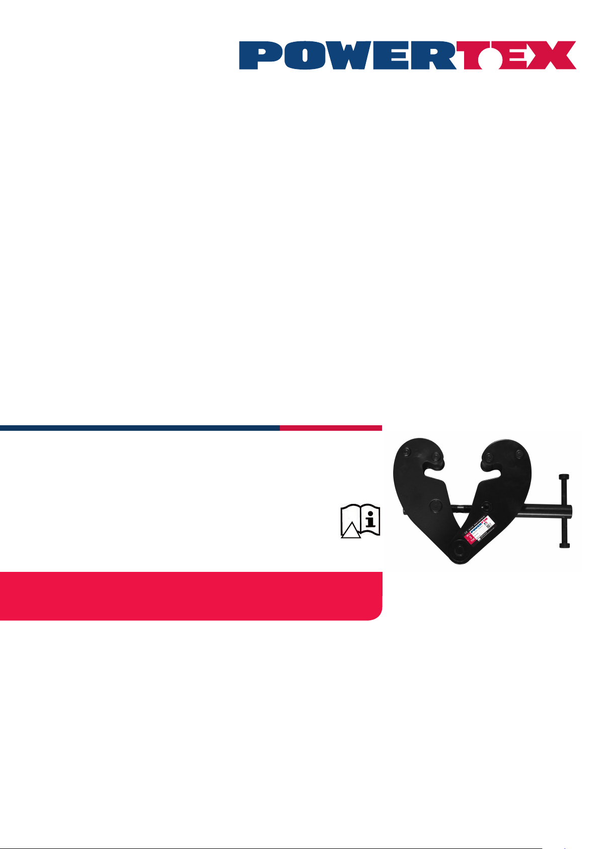
Beam Clamp PBC-S1
User Manual
UMPBC20190520DK
Page 2

POWERTEX Beam Clamp PBC-S1 1 – 10 ton
Assembly / Instruction for use (GB) (Original instructions)
Read through these user instructions carefully before using the beam
clamp. Improper operation may lead to hazardous situations!
The POWERTEX beam clamp is designed for mounting on the lower
ange of an I-beam for suspending a load or lifting device. The beam
clamp is xed in position with a right-hand and left-hand threaded rod
in a scissor construction.
Safety rules
• The beam on which the clamp is to be mounted must be checked
by a competent person. This person must assess the beam’s load
bearing capacity and xings and its suitability for the purpose.
• Check the beam clamp before use for function and any cracking,
deformation or wear.
• Load on the beam clamp must not exceed the maximum load indi-
cated on the rating plate.
• The beam clamp must only be used for beams with a ange width
within the range indicated on the rating plate.
• The clamp must be xed to the beam above the load’s centre of
gravity.
• Dynamic stresses must be avoided.
• Inclined pulls are not permitted.
• Working temperature: -10°C to +50°C.
Dimensioned sketch
Replacing the threaded rod.
1 Open the beam clamp as far as it will go.
2 Knock the locking pin out of the handle.
3 Completely unscrew the threaded rod.
4 Remove the old nuts by pressing them out of the beam clamp’s
arms. Dismantle and clean the spacers.
5 Mount the new nuts together with the spacers.
6 Oil and screw the new threaded rod into the nuts. Make sure both
threads go in simultaneously.
7 Screw up until the handle can be mounted and lock with the locking
pin.
8 Continue screwing to the desired position.
Instruction Grey Label
To change your new POWERTEX Beam Clamp to Black Line:
If the product should be used in dark environments, add the grey label
on the product’s name plate like this.
The data on the nameplate should ALWAYS be visible, and must NOT
be covered.
If the product is modied in any way, or if it is combined with a
non-compatible product / component, AxInter Lifting Solutions take
no responsibility for the consequences in regard to the safety of the
product
Technical data
Art No Model WLL I beam width rangeA max. B min. B max. C D E F min. F max. G min. H Weight
(ton) (mm) (mm) (kg)
16.02PBCS1010 PBC-S1 1 80-240 270 183 370 94 4 198 100 154 22 20 3,5
16.02PBCS1020 PBC-S1 2 80-240 270 183 370 102 6 198 100 154 22 20 4,5
16.02PBCS1030 PBC-S1 3 90-330 355 243 500 132 8 263 148 219 46 22 9,5
16.02PBCS1050 PBC-S1 5 90-330 355 243 500 142 10 263 148 219 43 28 11
16.02PBCS1100 PBC-S1 10 90-350 364 269 521 180 12 285 165 239 51 38 16
Safety factor: 4:1
Static test coefcient: WLL x 1,5
Generally according to EN 13155
Mounting
Open the beam clamp by unscrewing the threaded rod with the handle
sufciently to allow the clamp to enclose the beam. Screw up the
beam clamp centrally over the load’s centre of gravity. Make sure the
arms on the beam clamp have a secure grip on the beam ange. (See
dimensioned drawing).
The load or suspension hook on the lifting device must hang centrally
from the bowed centre of the suspension bolt.
Continuous maintenance - lubrication
Bearings and threaded sections and the surface of the suspension bolt
in contact with the load hook must be cleaned and lubricated as necessary. Periodic checks must normally be carried out yearly to detect
and remedy any faults. Damaged parts must be replaced with original
POWERTEX parts. A set of threaded rods and nuts can be ordered
through your dealer.
Contact your dealer for spare parts in general.
2
Page 3

POWERTEX Bjælkeklemme PBC-S1 1 – 10 ton
Montering / Brugsanvisning (DK)
Læs denne brugsanvisning, før bjælkeklemmen tages i brug. Forkert
brug kan medføre fare!
POWERTEX bjælkeklemme er beregnet til montering på den nederste
ange af en I-bjælke mhp. ophængning af last eller løfteanordning.
Bjælkeklemmen spændes fast ved hjælp af en stang med højre- og
venstregevind i en saksekonstruktion.
Sikkerhedsanvisninger
• Den bjælke, som bjælkeklemmen skal monteres på, skal være kontrolleret af en kvaliceret person. Denne person skal vurdere bjælkens
bæreevne og fastgørelser samt dens egnethed til formålet.
• Før brug kontrolleres bjælkeklemmen for evt. revner, deformation
og slitage, ligesom dens funktion kontrolleres.
• Bjælkeklemmen må ikke belastes med mere end maks.-lasten iht.
typeskiltet.
• Bjælkeklemmen må kun bruges til bjælker med en angebredde,
der ligger inden for det angivne område, jf. typeskiltet.
• Klemmen skal være fastgjort på bjælken lige over lastens tyngde-
punkt.
• Dynamiske påvirkninger skal undgås.
• Skævtrækning er ikke tilladt.
• Arbejdstemperatur: -10°C to +50°C.
Målskitse
Udskiftning af gevindstangen
1 Åbn bjælkeklemmen så meget den kan.
2 Bank låsepinden ud af håndtaget.
3 Skru gevindstangen helt løs.
4 Fjern de gamle møtrikker ved at trykke dem ud af bjælkeklemmens
arme. Demontér afstandsstykkerne og rengør dem.
5 Montér de nye møtrikker sammen med afstandsstykkerne.
6 Smør den nye gevindstang og skru den ind i møtrikkerne. Sørg for,
at de to gevind entrer samtidigt.
7 Stram så meget til, så håndtaget kan monteres, og lås med låsepin-
den.
8 Fortsæt med at skrue til den ønskede indstilling.
Instruktion grå label
Sådan ændrer du din nye POWERTEX Bjælkeklemme til Black Line:
Hvis produktet skal anvendes i mørke omgivelser, påfør grå etiket på
produktets typeskilt som denne.
Dataene på typeskiltet skal ALTID være synlige og må IKKE tildækkes.
Hvis produktet modiceres på nogen måder, eller kombineres med
ikke-kompatible produkter/komponenter, tager AxInter Lifting Solutions ingen ansvar for konsekvenserne i forhold til sikkerheden ved
produktet.
Tekniske data
Art. nr. Model WLL ton I bjælkebredde A maks. B min. B maks. C D E F min. F maks. G min. H Vægt
spændvidde (mm) (mm) (kg)
16.02PBCS1010 PBC-S1 1 80-240 270 183 370 94 4 198 100 154 22 20 3,5
16.02PBCS1020 PBC-S1 2 80-240 270 183 370 102 6 198 100 154 22 20 4,5
16.02PBCS1030 PBC-S1 3 90-330 355 243 500 132 8 263 148 219 46 22 9,5
16.02PBCS1050 PBC-S1 5 90-330 355 243 500 142 10 263 148 219 43 28 11
16.02PBCS1100 PBC-S1 10 90-350 364 269 521 180 12 285 165 239 51 38 16
Sikkerhedsfaktor: 4:1
Statisk test coefcient: WLL x 1,5
Standard: EN 13155
Montering
Bjælkeklemmen åbnes ved, at man skruer gevindstangen med håndtaget så meget op, at klemmen kan entre bjælken. Bjælkeklemmen
fastskrues lige over lastens tyngdepunkt. Sørg for, at bjælkeklemmens
arme får et sikkert greb om bjælkens ange. (Se måltegningen).
Lasten eller løfteanordningens ophængningskrog skal hænge lige på
ophængningsbøjlens neddrejede center.
Løbende vedligeholdelse – smøring
Lejer, gevindstang og ophængningsbøjlens kontaktade mod lastkrogen skal rengøres og smøres ved behov. Der skal foretages
regelmæssig kontrol, som hovedregel en gang om året, så eventuelle
dysfunktioner kan blive opdaget og afhjulpet. Beskadigede dele skal
udskiftes med originale POWERTEX-dele. Et gevindstangssæt med
møtrikker kan bestilles hos forhandleren.
Kontakt generelt din forhandler for reservedele.
Page 4

Product compliance and conformity
SCM Citra OY
Juvan Teollisuuskatui 25 C
02920 Espoo
Finland
www.powertex-products.com
4
Page 5

CERTEX Lifting KnowHow app
!
Download The Lifting KnowHow app’en from the App Store / Google play!
The App has the following features:
- Load charts for different types of lifting slings
- Protractor for measuring sling angles
- Instructions for safe use of a selection of lifting gear
- Built-in gps function that nds the Lifting Solutions Group ofce closest to
your position.
- And a lot more.
The Lifting KnowHow is a unique knowledge transfer programme.
CertMax+
The CertMax+ system is a unique leading edge certication management
system which is ideal for managing a single asset or large equipment portfolio across multiple sites. Designed by the Lifting Solutions Group, to deliver
optimum asset integrity, quality assurance and traceability, the system also
improves safety and risk management levels.
User Manuals
You can always nd the valid and updated User Manuals on the web.
The manual is updated continuously and valid only in the latest version.
NB! The English version is the Original instruction.
The manual is available as a download under the following link:
www.powertex-products.com/manuals
Page 6

Canary Islands
www.powertex-products.com
 Loading...