

Powertec Pro BD6900 Owner's Manual
Model No. BD6900
QUESTION...
1•877•393•7121
Owner’s Manual
6”x 9” DISC/BELT SANDER
WITH BUILT-IN DUST COLLECTION
Visit us on the web at www.southerntechllc.com
You will need this manual for safety instructions, operating procedures, and warranty.
Put it and the original sales invoice in a safe, dry place for future reference.
10-0419
TABLE OF CONTENTS
PRODUCTION
SECTION PAGE
SAFETY RULES 1
Work Preparation
Work Area Preparation
Tool Maintenance
Tool Operation
ASSEMBLY 2
Unpackaging
Tool Needed
Mount Sander
Attach Abrasive Disc
Attach the Table Assembly to Use with Sanding Disc
Attach the Table Assembly to Use with Sanding Belt
Attach Dust Collection Bag
Power Source
Grounding Instructions
Extension Cords
Motor
Electrical Connections
OPERATION 6
SPECIFICATIONS
Horsepower (Peak HP).................................................. 1.2
Voltage...........................................................................120
Amp................................................................................7.5
Hertz................................................................................60
Phase.........................................................................Single
RPM.............................................................................3450
Belt size...................................................................6” x 48”
Belt speed...........................................................2400 FPM
Disc diameter....................................................................9”
Disc speed..........................................................3100 RPM
Table dimensions....................................................7” x 10”
Table tilts...............................................................0° to 45°
Dust port diameter............................................................2”
Base dimensions...................................................12” x 19”
ON/OFF Switch
Adjust Belt Tracking Mechanism
Adjust Belt Assembly Position
Adjust Table Tilt Angle
Belt Sanding in Horizontal Position
Operate Sanding Belt
Operate Sanding Disc
Set Up the Miter Gauge
Replace Sanding Belt
Replace Sanding Disc Abrasive
MAINTENANCE 9
General Maintenance
Cleaning
Lubrication
Keep Tool in Repair
TROUBLESHOOTING 10
PARTS ILLUSTRATION & 11
LIST
WARRANTY 14

SAFETY RULES
1
WARNING
For your own safety, read and understand all warnings
and operating instructions before using any tool or
equipment.
WARNING
Some dust created by operation of power tool contains
chemicals known to the State of California to cause
cancer, birth defects or other reproductive harm.
To reduce your exposure to these chemicals: work in a
well ventilated area and work with approved safety
equipment. Always wear OSHA/NIOSH approved,
properly fitting face mask or respirator when using such
tools.
WARNING
Failure to follow these rules may result in serious personal
injury. Remember that being careless for even a fraction
of a second can result in severe personal injury.
WORK PREPARATION
• Wear proper apparel. Do not wear loose clothing,
gloves, neckties, rings, bracelets or other jewelry which
may get caught in moving parts of the tool.
• Nonslip protective footwear is recommended.
• Wear protective hair covering to contain long hair.
• Wear eye and hearing protection. Always use safety
glasses. Eye protection equipment should comply with
ANSI Z87.1 standards. Hearing equipment should
comply with ANSI S3.19 standards.
• Wear face mask or dust mask if operation is dusty.
• Be alert and think clearly. Never operate power tools
when tired, intoxicated or when taking medications that
cause drowsiness.
WORK AREA PREPARATION
• Keep work area clean. Cluttered work areas and
benches invite accidents.
• Work area should be properly lighted.
• Do not use the machine in a dangerous environment.
The use of power tools in damp or wet locations or in
rain can cause shock or electrocution.
• Three-prong plug should be plugged directly into
properly grounded, three-prong receptacle.
• Use the proper extension cord. Make sure your
extension cord is in good condition and should have a
grounding prong and the three wires of
extension cord should be of the correct gauge.
• Keep children and visitors away. Your shop is a poten tially dangerous environment. Children and visitors can
be injured.
• Make your workshop childproof with padlocks, master
switches or remove switch keys to prevent any uninten tional use of power tools.
TOOL MAINTENANCE
• Turn the machine "OFF", and disconnect the machine
from the power source prior to inspection.
• Maintain all tools and machines in peak condition. Keep
tools sharp and clean for best and safest performance.
• Follow instructions for lubricating and changing
accessories.
• Check for damaged parts. Check for alignment of
moving parts, binding, breakage, mounting and any
other condition that may affect tool's operation.
• Poorly maintained tools and machines can further
damage the tool or machine and/or cause injury.
• A guard or any other part that is damaged should be
repaired or replaced. Do not perform makeshift repairs.
TOOL OPERATION
• Avoid accidental start-up. Make sure that the tool is in
the “OFF” position before plugging in.
• Use the right tool for your job. Do not force your
tool or attachment to do a job for which it was not
designed.
• Disconnect tool when changing parts.
• Don't force the workpiece on the machine. Damage to
the machine and/or injury may result.
• Never leave tool running unattended. Turn the power off
and do not leave tool until it comes to a complete stop.
• Do not overreach. Loss of balance can make you fall
into a working machine, causing injury.
• Never stand on tool. Injury could occur if the tool tips, or
if you accidentally contact the cutting tool.
• Know your tool. Learn the tool’s operation, application
and specific limitations before using it.
• Use recommended accessories. Use of improper
accessories may cause damage to the machine or injury
to the user.
• Handle workpiece correctly. Keep hands away from
moving parts.
• Turn tool off if it jams.
• Always feed workpiece against the direction of the
sanding rotation. To maintain control, properly support
long or wide work-pieces.
CAUTION: Think safety! Safety is a combination of operator common sense and alertness at all times when tool is
being used.
WARNING
Do not attempt to operate tool until it is completely
assembled according to the instructions.
2
B
A
C
D
E
F
G
H
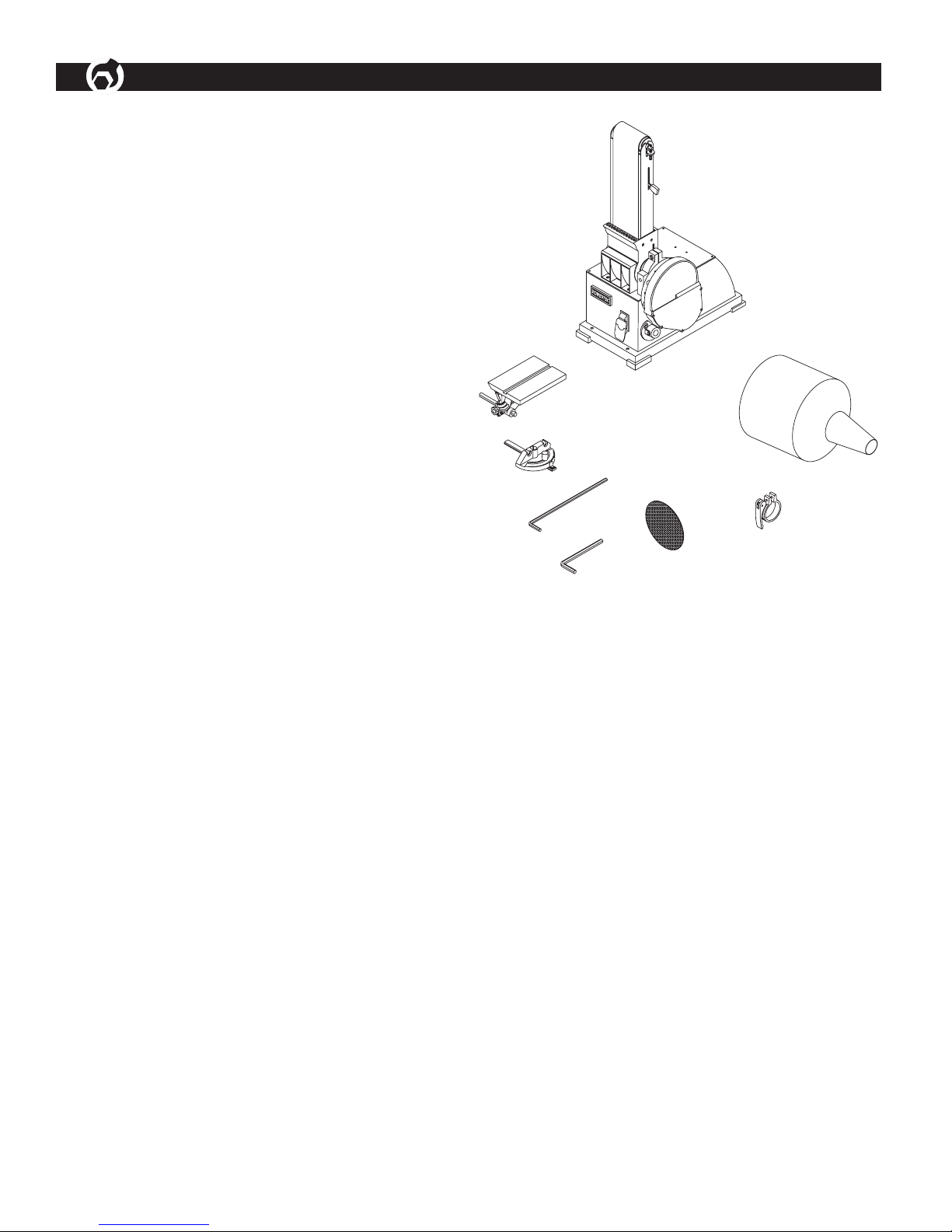
ASSEMBLY
UNPACKING
Refer to Figure 1.
Check for shipping damage. Check immediately whether
all parts and accessories are included.
The sander comes assembled as one unit. Additional
parts which need to be fastened to sander, should be
located and accounted for before assembling.
ITEM DESCRIPTION QUANTITY
A Sander 1
B Dust Collection Bag 1
C Bag Clamp 1
D Mitre Gauge Assembly 1
E Table Assembly 1
F Disc 1
G Wrench (4 mm) 1
H Wrench (6 mm) 1
Figure 1
WARNING
c
a
b
j h dli
g
k
Do not use the machine until it is completely assembled
and you have read and understood the entire operating
manuals.
TOOLS NEEDED
You will need the following tools to assemble and adjust
the machine. (The tools are not included.)
• 10mm Wrench
• 5 and 6mm Hex Wrenches
• Combination Square
• Phillips Screwdriver
MOUNT SANDER
• The machine must be installed in a well-lighted area
with correct power supply.
• The machine can be installed on either a workbench or
a tool stand by using bolts, lock washers, and hex nuts.
• The machine must be bolted to a firm and level surface.
• There must be enough clearance for the moving
workpiece during operation. There must be enough
room for safety operation of the machine.
• Slide the Table Assembly (g) onto the Supporting Rod
(d) and position the table platform in level position.
• Adjust the distance between the table platform and
the Sanding Disc so it is 1/16” or less. Do not allow the
Sanding Disc to touch any part of the Table Assembly
(g).
• Secure the Table Assembly (g) in position with the Bolt
(h). Tighten the Bolt (h) against the flat surface of the
Supporting Rod (d). Check that Table Assembly (g) is
stable.
• Set the table 90 degree (Perpendicular) to the Sanding
Disc with a Combination Square. Secure the table in
position by tightening the knob (j) on the tilt angle scale
under the table platform.
• Zero the angle indicator: set the pointer (k) to 0 degree.
Figure 3
ASSEMBLY
3
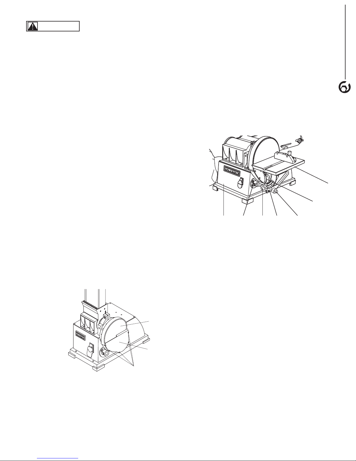
ATTACH ABRASIVE DISC
Refer to Figure 2
• Remove all screws (b) and remove the Disc Cover (a).
• Clean the surface of the aluminum disc.
• Peel off the protective paper on the back of the Abrasive
Disc (c).
• With the adhesive side facing the aluminum disc,
carefully place the Abrasive Disc (c) onto the center of
aluminum disc.
• Confirm the position is satisfactory before press the
Abrasive Disc (c) firmly and evenly against the
aluminum disc in the entire area.
• Replace the Disc Cover (a) and tighten with screws (b).
Figure 2
ATTACH THE TABLE ASSENBLY TO USE
WITH SANDING DISC
Refer to Figure 3
• Insert the Supporting Rod (d) into the mount on the side
of base (i), to the left lower corner of the Sanding Disc.
• Secure the Supporting Rod (d) onto the base (i) by
tightening the Bolt (l) against the flat surface of the
Supporting Rod (d). Check that Supporting Rod (d) is
stable and will not roll.
ATTACH THE TABLE ASSEMBLY TO USE
WITH SANDING BELT
Refer to Figure 4
• With the Sanding Belt Assembly in upright position,
locate the Mount (e) of side of Sanding Belt Assembly.
• Insert the Support Rod (d) into the Mount (e). Secure
the Supporting Rod (d) onto the Mount (e) by tightening
the Bolt (f) against the flat surface of the Supporting Rod
(d). Check that Supporting Rod (d) is stable and will not
roll.
• Slide the Table Assembly (g) onto the Supporting Rod
(d) and position the table platform in level position.
• Adjust the distance between the table platform and the
Sanding Belt so it is 1/16” or less. Do not allow the
Sanding Belt to touch any part of the Table Assembly
(g).
• Secure the Table Assembly (g) in position with the Bolt
(h). Tighten the Bolt (h) against the flat surface of the
Supporting Rod (d). Check that Table Assembly (g) is
stable.
• Set the table 90 degree (Perpendicular) to the Sanding
Belt with a Combination Square. Secure the table in
position by tightening the knob (j) on the tilt angle scale
under the table platform.
• Zero the angle indicator: by setting the pointer (k) to 0
degree.
ASSEMBLY
j
h
k
g
d
n
m
f
e
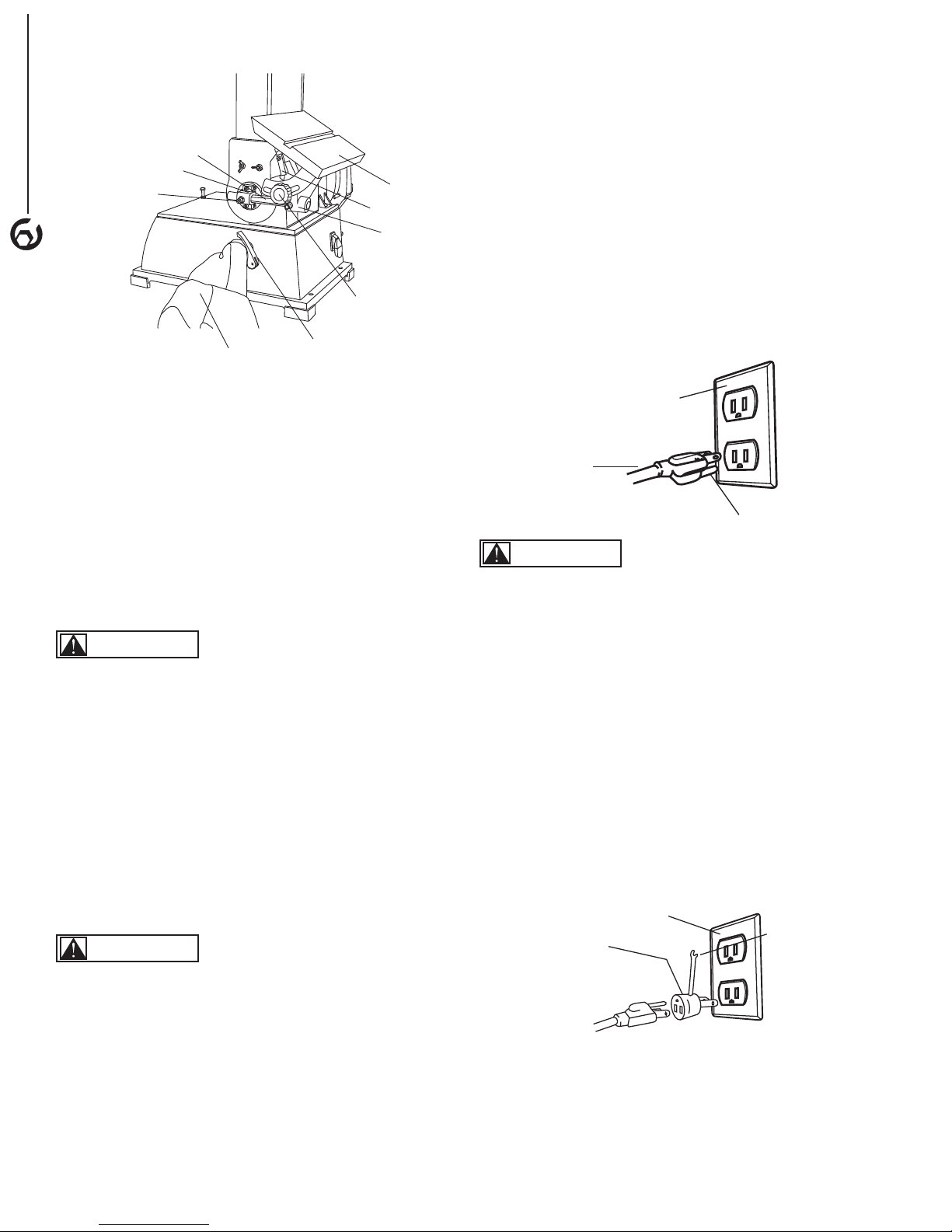
Grounded outlet Box
3 - Prong Plug
Grounding Prong
Grounding
Means
Grounded outlet Box
Adapter
4
Figure 4
• Grounding plug should be plugged directly into a
properly installed and grounded 3-prong grounding-type
receptacle, as shown (Figure 5)
• The plug must be plugged into an outlet that is properly
installed and grounded in accordance with all local
codes and ordinances.
• Check with a qualified electrician or service personnel if
these instructions are not completely understood or if in
doubt as to whether the tool is properly grounded.
• Do not modify plug provided. If it will not fit in outlet,
have proper outlet installed by a qualified electrician.
Use only 3-wire extension cords, that have 3-prong
grounding type plugs and matching 3-conductor
receptacles that accept the machine's plug, as show in
Figure 5
ATTACH THE DUST COLLECTION BAG
Refer to Figure 3
• Slide the Clamp (m) over the Sleeve of Dust Collection
Bag (n).
• Locate the Dust Port on the side of the Base.
• Place the Dust Collection bag (n) and Clamp over the
Dust Port. If necessary, adjust the size of the Clamp (m)
opening by rotating the handle on the Clamp (m).
• Tighten the Clamp (m) by pressing the handle. Check
that the Dust Collection Bag (n) is securely attached to
the Dust Port.
POWER SOURCE
WARNING
Do not connect to the power source until the machine is
completely assembled.
The machine is wired for 120 volts, 60 HZ alternating
current. Before connecting the machine to the power
source, make sure the switch is in the "OFF" position.
Running the unit on voltages which are not within range
may cause overheating and motor burn-out. Heavy loads
require that voltage at motor terminals be no less than the
voltage specified on nameplate.
• Power supply to the motor is controlled by a locking
rocker switch. Remove the key to prevent unauthorized
use.
Figure 5
WARNING
Do not permit fingers to touch the terminals of plug when
installing or removing from outlet.
• Inspect tool cords periodically, and if damaged, have
repaired by an authorized service facility.
• The conductor with insulation having an outer surface
that is green with or without yellow stripes is the
equipment-grounding conductor. If repair or replacement
of the electric cord or plug is necessary, do not connect
the green (or green and yellow) wire to a live terminal.
A temporary 3-prong to 2-prong grounding adapter (see
Figure 6) may be used to connect this plug to a matching
2-conductor receptacle as shown in figure 6. The
temporary adapter should be used only until a properly
grounded outlet can be installed by a qualified electrician.
Figure 6
GROUNDING INSTRUCTIONS
WARNING
Improper connection of equipment grounding conductor
can result in the risk of electrical shock.
• The machine should be grounded while in use to protect
operator from electrical shock.
• In the event of an electrical short circuit, grounding
reduces the risk of electrical shock by providing an
escape wire for the electric current.
• This machine is equipped with an approved
3-conductor cord rated at 150V and a 3-prong
grounding type plug for your protection against shock
hazards.
In Canada, the use of temporary adapter is not permitted
by the Canadian Electric Code. Where permitted, the rigid
green tab or terminal on the side of the adapter must be
securely connected to a permanent electrical ground such
as a properly grounded water pipe, a properly grounded
outlet box or a properly grounded wire system.
 Loading...