

FCC Verification
This equipment has been tested and found to comply with the limits for a Class B digital device, pursuant
to Part 15 of the FCC Rules. These limits are designed to provide reasonable protection against harmful
interference in a residential installation. This equipment generates, uses and can radiate radio frequency
energy and, if not installed and used in accordance with the instructions, may cause harmful interference
to radio communications. However, there is no guarantee that interference will not occur in a particular
installation. If this equipment does cause harmful interference to radio or television reception, which can
be determined by turning the equipment off and on, the user is encouraged to try to correct the
interference by one or more of the following measures:
-- Reorient or relocate the receiving antenna.
-- Increase the separation between the equipment and receiver.
-- Connect the equipment into an outlet on a circuit different from that to which the receiver is
-- Consult the dealer or an experienced radio/TV technician for help.
To assure continued FCC compliance:
1. Any changes or modifications not expressly approved by the grantee of this device could void the
user's authority to operate the equipment.
2. This equipment complies with FCC radiation exposure limits set forth for an uncontrolled environment.
This equipment should be installed and operated with minimum distance 20cm between the radiator &
your body.
This device complies with Industry Canada license-exempt RSS standard(s). Operation is subject to the
following two conditions: (1) this device may not cause interference, and (2) this device must accept any
interference, including interference that may cause undesired operation of the device.
This equipment complies with IC radiation exposure limits set forth for an uncontrolled environment.
This equipment should be installed and operated with minimum distance 20cm between the radiator and
your body.
Economic Development Canada to operate with the antenna types listed below, with the maximum
permissible gain indicated. Antenna types not included in this list that have a gain greater than the
maximum gain indicated for any type listed are strictly prohibited for use with this device.
Cet appareil radio est conforme au CNR-247d’Industrie Canada. L’utilisation de ce dispositif est
autorisée seulement aux deux conditions suivantes : (1) il ne doit pas produire de brouillage, et (2)
l’utilisateur du dispositif doit être prêt à accepter tout brouillage radioélectrique reçu, même si ce
brouillage est susceptible de compromettre le fonctionnement du dispositif.
Cet équipement est conforme aux limites d’exposition aux rayonnements IC établies pour un
environnement non contrôlé. Cet équipement doit être installé et utilisé avec un minimum de 20 cm de
distance entre la source de rayonnement et votre corps.
connected.
FCC Part15C+RSS247
IC
This radio transmitter (IC: 3653A-ASP603W) has been approved by Innovation, Science and
Antenna Type: Dipole antenna
Model Name: Q0211
Gain (Peak): 2 dBi
French:
AS-P-603W
Home Theater Smart Power Center
© Copyright 2019 Metra Electronics
The information contained herein is subject to change without noti ce. This
document contains proprietary informati on protected by copyright law. No
part of this document may be photocopied or reproduced without prior
written consent.
metrahometheater.com
User Guide
Model AS-P-603W

TABLE OF CONTENTS
INTRODUCTION
Introducon .................................................................................................... 2
Features .............................................................................................................. 2
Safety Information .............................................................................................. 2
Package Contents ................................................................................................ 2
Installaon ...................................................................................................... 3
Descriptions .................................................................................................... 4
Operation ........................................................................................................ 5
LCD Control Panel ............................................................................................... 5
LED Indicators ..................................................................................................... 5
Remote Trigger Operation................................................................................... 5
Specifications .................................................................................................. 6
App Setup ....................................................................................................... 7
App Operation ............................................................................................... 10
Thank you for purchasing the AS-P-603W. Your new home theater power solution
provides clean AC power to sensitive home theater electrical equipment. Four smart
outlets, four switched outlets and one always on front outlet (nine total) provide
premium surge protection and noise filtering. Additional connections supply two
pairs of DSS/coaxial connections for cable protection.
Features
• Three kinds of lter circuitry isolates and protects digital, analog and high current
equipment.
• LCD display shows voltage and amperage levels.
• System provides overload protection with a 120V/15A electrical rating.
• Remote 110V and 12V DC trigger allows remote turn on/off of switched outlets.
• DSS/coax surge protection provided.
• A total of nine outlets includes 4 switched and 4 smart and 1 front always on.
Safety Information
• To reduce the risk of electrical shock, unplug the AS-P-603W and allow it to cool
before cleaning.
• There are no replaceable parts in the AS-P-603W. Do not attempt to disassemble
this unit for any reason.
• Use in an indoor, dry location only.
Package Contents
• Home Theater AS-P-603W
surge protector/conditioner
• This User Manual
AS-P-603W
AS-P-603W
Page 2Page 1
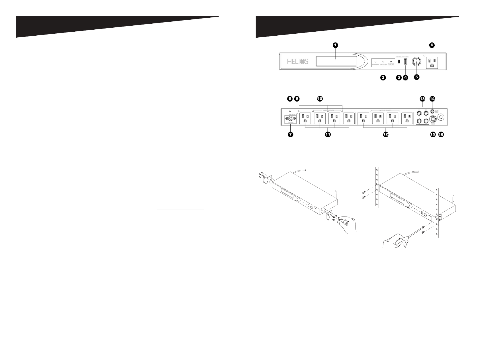
INSTALLATION
1. LCD Display - Monitor the AS-P-603W's main functions.
2. LED Power Indicators – Monitor ground, protection and switched power statuses.
3. USB C - 3A USB C connection for charging devices.
4. USB A - 2.4 Amp USB A connection for charging devices.
5. Power Switch - Switches on and off the four (4) switched outlets on the back.
6. Always on Outlet - Always on AC outlet.
7. Wi-Fi Antenna - Provides connection to Wi-Fi for remote control from Tuya App.
8. Wi-Fi Activity LED - Shows Wi-Fi status and used during Tuya App setup.
9. Wi-Fi Reset button - Used to reset the Wi-Fi connection.
10. Smart Outlet Status LEDs - Shows smart outlet on/off state.
11. Smart AC Outlets - Four (4) Smart AC Outlets that can be controlled remotely by
the Tuya App.
12. Switched AC Outlets - Four (4) switched AC outlets that are controlled by the
power switch on the front of the AS-P-603W.
13. DSS/Coax Line Input/Output – Protect coaxial cable lines from power surges and
spikes that can disturb and damage your equipment. Connect your cable TV,
satellite TV, antenna, HDTV, broadband or other coaxial cable lines.
14. DC IN – Control the switched outlets using the remote trigger function of another
power management unit.
15. 15-Amp Overload Reset-able Circuit Breaker – Provides overload protection with
a manually recoverable function.
16. Power Cord - 14 gauge insulated power cord.
17. Includes detachable rack mount ears and thumb screws for temporary mounting.
This power center for TEMPORARY MOUNTING ONLY. NOT INTENDED FOR
PERMANENT MOUNTING.
DESCRIPTIONS
Figure 2 - Front View Controls and Indicators
Figure 3 - Rear View Controls
Remote Operation
Download App titled "Tuya Smart" from Google Play store or Apple app store
for easy remote operation of the 4 smart outlets
Page 3 AS-P-603W AS-P-603W Page 4
Step 1. Use included thumb screws
to attach rack ears to power center.
Figure 4 - Optional Rack ear installation
Step 2. Install screws in the upper and
lower mounting holes to secure power
center to the rack.
OPERATION
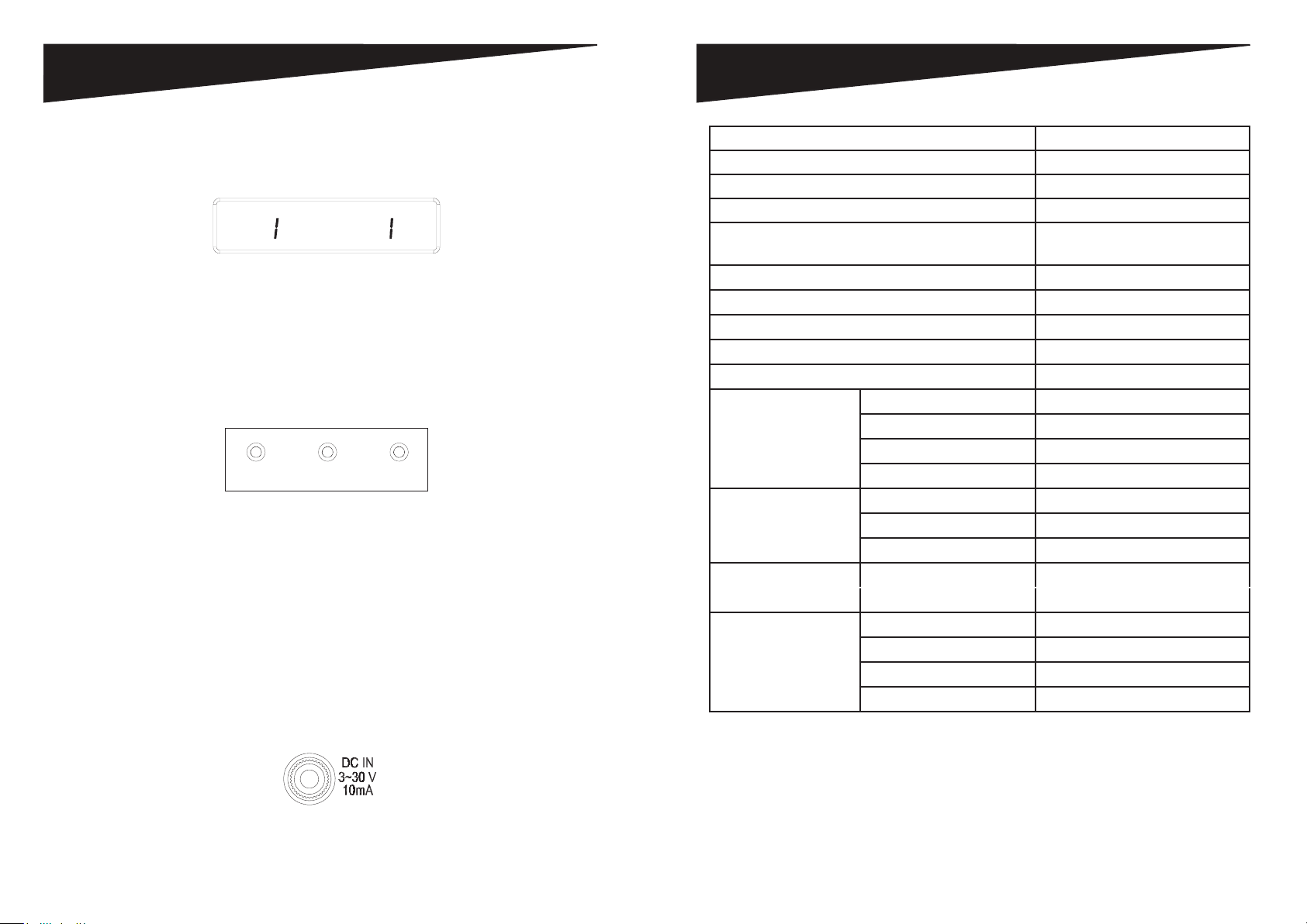
SPECIFICATIONS
LCD Panel
The AS-P-603W is equipped with an LCD Panel (Figure 5) that allows the user
to monitor input voltage and output current.
VOLTS CURRENT
20
Figure 5 - LCD Panel
• “VOLT” indicates the input voltage from the AC wall outlet.
• “AMPS” indicates the output current from the outlet banks.
LED Indicators
The LED indicators on the front panel (Figure 6) allow you to monitor
important power and safety information.
GROUNDED
Figure 6 - Front Panel LED Indicators
• “GROUNDED” indicates the status of the AC outlet. Green indicates that the AC
wall outlet is properly grounded.
• “PROTECTED” indicates the status of the Power Soluon surge protecon. Orange
indicates that the surge protecon is turned on.
• “SWITCHED POWER” indicates whether the “Switched” outlets are ON or OFF.
Remote Trigger Operation
This AS-P-603W can be controlled remotely by another power solution equipped with
a remote trigger out feature. To use remote trigger control, connect the remote DC
cable from the “DC OUT” connection on the power solution equipped with remote
trigger out to the “DC IN” connection (Figure 7) on the AS-P-603W.
PROTECTED SWITCHED
5.0
OUTLETS
Width 482.6mm
Height 44mm
Length 220.1mm
Weight 3.5kgs
Power Cord 14 AWG with 36 degree angle
(8 Feet)
Electrical Rang 120V/15A
Clamping Voltage L-N 400V, L-G 500V, N-G 500V
Surge Energy Joule Rang 2160J
Maximum Peak Spike Current 144000A
Maximum Spike Voltage 6KV
EMI/RFI Noise Filter X2 Capacitor (uF) 1.0uF*1; 0.22uF*1
Coil (T) 1mH*1
Frequency (KHz) 150KHz~100MHz
Aenuaon (dB) up to 65dB
DC Trigger Input Jack ψ 3.5
Voltage 3~30V
Current Requirement 10mA
USB Charger
DSS/COAX Cable
Protecon
NOTE: Specicaons subject to change without noce.
Total Output
Surge Arrestor Gas Tube
Breakdown Voltage <75V
Inseron Loss @10MHz <0.1dB
RF Connectors 3 Pairs, Gold nish
Total 5V/4.8A
USB-A Output up to 5V/2.4A
USB-C Output up to 5V/3A
Figure 7 - DC IN Connection
AS-P-603W
Page 6Page 5 AS-P-603W
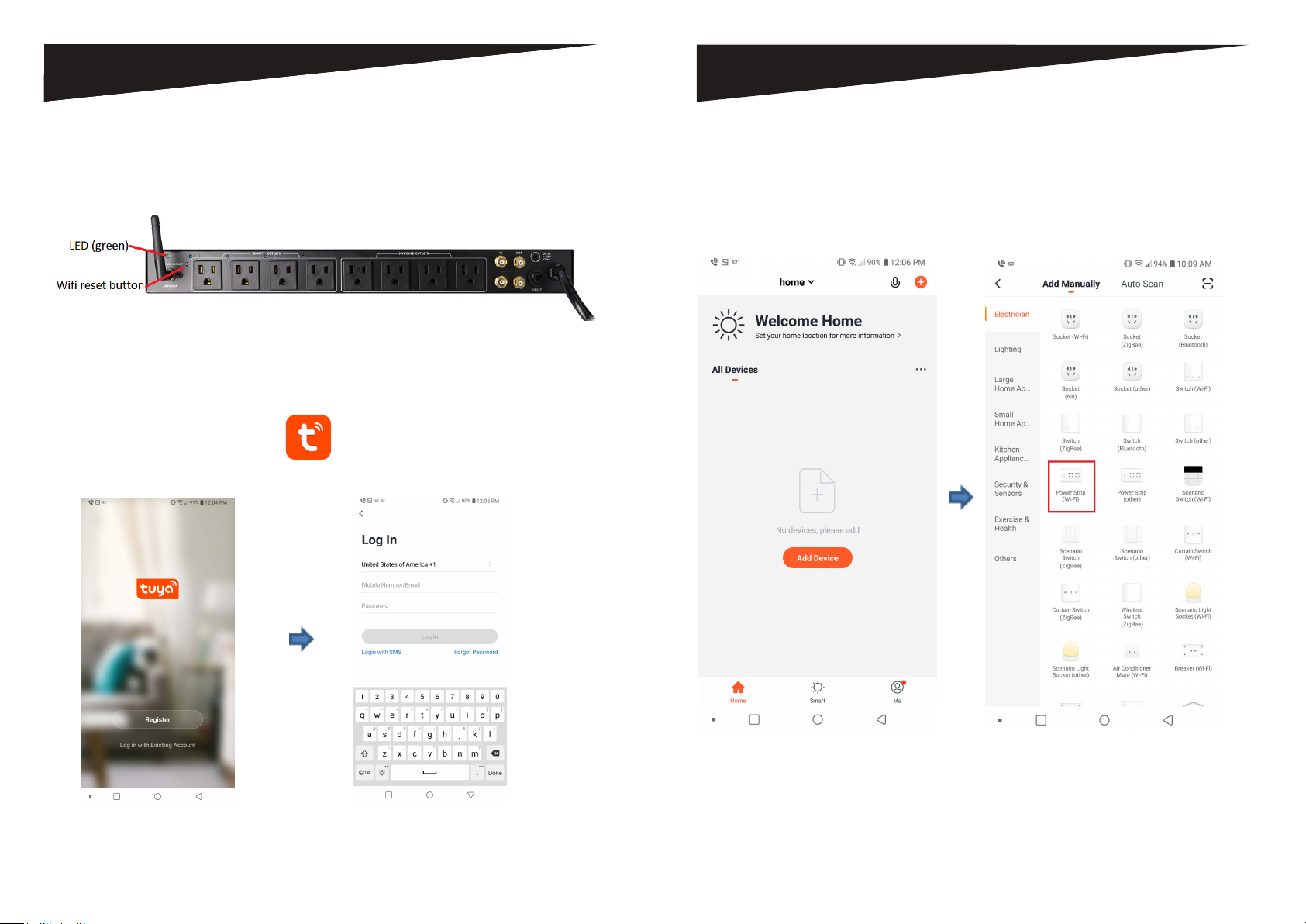
APP SETUP
Device setup for app connection
Press the wifi reset button for 8 seconds or until you see the wifi LED (green) blinking
and then release the wifi reset button to connect to the app.
App installation & setup
1. Connect Android or iOS device to wifi router
2. Download and install Tuya app from Google play store or Apple App
store.
3. Register new account or login to existing account.
APP SETUP
4. After logging into the app, add the
device.
5. Select "Power Strip (Wi-Fi)"
AS-P-603W Page 8Page 7 AS-P-603W
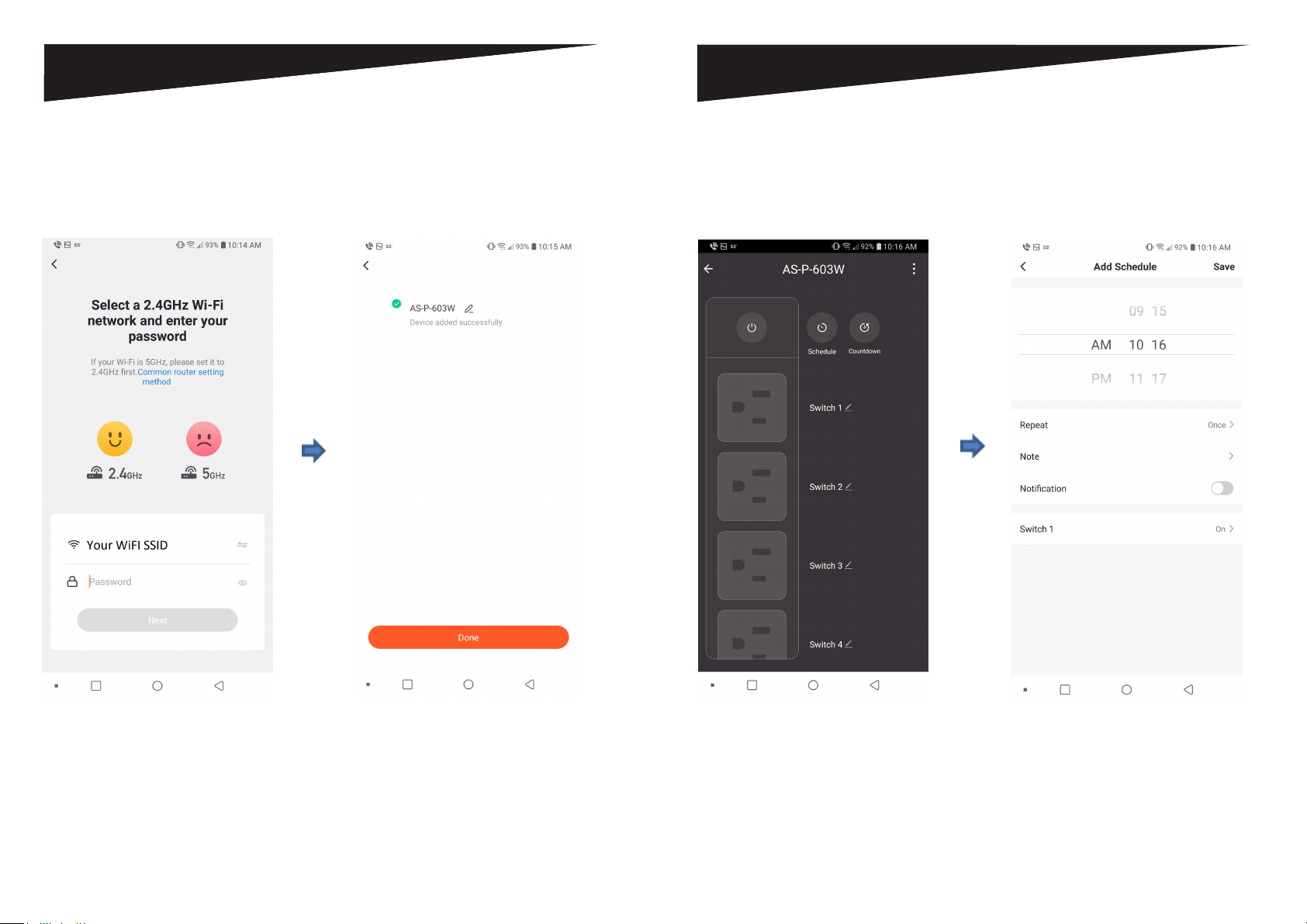
APP SETUP
APP OPERATION
6. Enter WiFi credentials for 2.4GHz
Network.
7. Device added successfully. Select
device.
8. Turn outlets on or off by tapping
individual or all outets. Tap
Schedule to create schedules per
outlet.
9. Set schedule per outlet by time.
AS-P-603W Page 10Page 9 AS-P-603W
 Loading...