

Page 1

PL300E / PL400E / PL500E / PL800E
SLIDING GATE OPENERS
24V DC MOTOR
FOR RESIDENTIAL
USER MANUAL
Page 2

Declaration of Conformity
Model: PL300E, PL400E, PL500E, PL800E, PR-1
1. Certificate of conformity of a product with the essential requirements art. 3.2 of the R&TTE Directive 1999/5/EC.
2. The above product has been tested with the listed standards and in compliance with the European Directive LVD
2006/95/EC.
3. The submitted sample of the above product has been tasted for CE marking according to the following European Directives:
2006/42/EC Machinery Directive.
Comply with the following Standards:
EN 301489-1 V1.8.1: 2008
EN 301489-3 V1.4.1: 2002
EN 300220-1 V2.1.1: 2006
EN 300220-2 V2.1.2: 2007
EN 60335-1: 2002+A11:2004+A1:2004+A12:2006+A2:2006+A13:2008
EN 60335-2-103: 2003
EN 62233: 2008
EN 12445: 2001
EN 12453: 2001
And also declare that the machinery may not be put into service until the machine, which will be integrated or become one of
the components, and announced to comply with the provisions as the required.
Page 3

INDEX
1. Warnings
2. Installation
2.1 Standard Installation Demonstartion
2.2 Description of Device
2.3 Dimension of Device
2.4 Installation of Motor Gear and Gear Rack
2.5 Checking for Installation
2.6 Emergency Release
3. Setup and Function Setting
3.1 Wire Connection
3.2 Transmitter Memorization and Erasing Process
3.3 System Learning, Reset Process and LED Display
3.4 Programmable Function Settings
3.5 Testing and Checking
P. 2
P. 3
P. 3
P. 3
P. 4
P. 4
P. 5
P. 5
P. 6
P. 6
P. 7
P. 7
P. 8
P.10
3.6 SW2/SW6 Setting
4. Technical Characteriestics
4.1 Technical Data Sheet of Series
4.2 PH-1 Photocell Data Sheet
4.3 PR-1 Transmitter Data Sheet
4.4 PF-1 Flashing Light Data Sheet
4.5 PRB-1 External Receiver Box Data Sheet
5. Additional Information
5.1 Wire Connection of PH-1 Photocell (Safety Beam)
5.2 Wire Connection and Setting Of PRB-1 External Reciever Box
5.3 Green Box Installation Guide
P.10
P. 11
P. 11
P. 11
P. 11
P. 11
P. 11
P.12
P.12
P.13
P.14
INSTRUCTIONS PL300E/PL400E/PL500E/PL800E SLIDING GATE OPENER USER MANUAL
1
Page 4

1) Warnings
Please read this instruction manual carefully before the installation of
gate-automated system.
This manual is exclusively for qualified installation personnel. The
manufacturer is not responsible for improper installation and failure to
comply with local electrical and building regulations.
Keep all the components of PL300E / PL400E / PL500E / PL800E system
and this manual for further consultation.
In this manual, please pay extra attention to the
contents marked by the symbol:
● Be aware of the hazards that may exist in the procedures of installation
and operation of the gate-automated system. Besides, the installation
must be carried out in conformity with local standards and regulations.
● If the system is correctly installed and used following all the standards
and regulations, it will ensure a high degree of safety.
● Make sure that the gates works properly before installing the
gate-automated system and confirm the gates are appropriate for the
application.
● Do not let children operate or play with the gate-automated system.
● Do not cross the path of the gate-automated system when operating.
● Please keep all the control devices and any other pulse generator away
from children to avoid the gate-automated system being activated
accidentally.
● Do not make any modifications to any components except that it is
mentioned in this manual.
● Do not try to manually open or close the gates before you release the
gear motor.
● If there is a failure that cannot be solved and is not mentioned in this
manual, please contact qualified installation personnel.
● Do not use the gate-automated system before all the procedures and
instructions have been carried out and thoroughly read.
● Test the gate-automated system weekly and have qualified installation
personnel to check and maintain the system at least every 6-month.
● Install warning signs (if necessary) on the both sides of the gate to warn
the people in the area of potential hazards.
This appliance can be used by children aged from 8 years and above and
persons with reduced physical, sensory or mental capabilities or lack of
experience and knowledge if they have been given supervision or
instruction concerning use of the appliance in a safe way and understand
the hazards involved. Children shall not play with the appliance.
Cleaning and user maintenance shall not be made by children without
supervision. The instructions shall state the substance of the following:
WARNING: Important safety instructions. It is important for the safety of
persons to follow these instructions. Save these instructions.
The instructions shall include the substance of the following:
– do not allow children to play with fixed controls. Keep remote controls away
from children;
– explanation of mode indicators;
– details on how to use any manual release, and if applicable, state that
activation of the manual release may cause uncontrolled movement of the
driven part due to mechanical failures or an out-of-balance condition;
– when operating a biased-off switch, make sure that other persons are
kept away;
– when closing a window that has been opened by a fire-sensing system, make
sure that other persons are kept away;
– frequently examine the installation for imbalance and signs of wear or
damage to cables, springs and mounting. Do not use if repair or adjustment is
necessary;
– disconnect the supply when cleaning or other maintenance is being carried
out, if the appliance is automatically controlled.
The installation instructions shall state the substance of the following:
WARNING: Important safety instructions. Follow all instructions since incorrect
installation can lead to severe injury.
The installation instructions shall specify the type, size and mass of the driven
part, and locations where the drive can be
installed. They shall state that the installer is to check that the temperature
range marked on the drive is suitable for the
location.
The installation instructions shall include the substance of the following:
– the necessary information for safe handling of a drive weighing more than
20 kg. This information shall describe how to use the handling means, such
as hooks and ropes;
– before installing the drive, check that the driven part is in good mechanical
condition, correctly balanced and opens and closes properly;
– information if the drive is intended to be installed at a height of at least 2,5 m
above floor level or other access level;
– that the drive cannot be used with a driven part incorporating a wicket door
(unless the drive cannot be operated with the wicket door open);
– ensure that entrapment between the driven part and the surrounding fixed
parts due to the opening movement of the
driven part is avoided;
– details for the installation of the drive and its associated components,
including any noninherent protection devices or deformable edges;
– that the actuating member of a biased-off switch is to be located within direct
sight of the driven part but away from moving parts. Unless it is key operated,
it is to be installed at a minimum height of 1,5 m and not accessible to the
public;
– that windows, having a gap exceeding 200 mm when open, are to be closed
using a biased-off switch if the opening movement is controlled by a
fire-sensing system;
– details on how to set controls;
– after installation, ensure that the mechanism is properly adjusted and that the
protection system and any manual release function correctly;
– permanently fix the label concerning the manual release adjacent to its
actuating member.
Rohs Warnings
Correct Disposal of this product
This marking indicates that this product should not be disposed with
other household wastes throughout the EU. To prevent possible harm
to the environment or human health from uncontrolled waste disposal,
recycle it responsibly to promote the sustainable reuse of material
resources. To return your used device, please use the return and
collection systems or contact the retailer where the product was
purchased. They can take this product for environmental safe
recycling.
2
INSTRUCTIONS PL300E/PL400E/PL500E/PL800E SLIDING GATE OPENER USER MANUAL
Page 5

2. Installation:
2.1 Standard Installation Demonstration
4
3
1. 24V DC sliding motor
2. Transmitter
3. Safety photo sensor
4. Flashing light
2.2 Description of Device
3
1
2
g
d
a. Operation gear
b. Limit switch device
c. 24Vdc motor
d. Back-up batteries (Optional)
c
f
h
b
e
a
e. Release device
f. Control panel
g. Terminals of devices
h. Green Box (Optional)
INSTRUCTIONS PL300E/PL400E/PL500E/PL800E SLIDING GATE OPENER USER MANUAL
3
Page 6

2.3 Dimension of Device
1~2m
2.4 Installation of Motor Gear and Gear Rack
4
>100
50>25
25
INSTRUCTIONS PL300E/PL400E/PL500E/PL800E SLIDING GATE OPENER USER MANUAL
Page 7

2.5 Checking for Installation
DXSX
NO
OK
2.6 Emergency Release
In the case of power failure for emergency release of the motor, please follow the procedure
as below:
Step1. Push the lid of release chamber and move rightward
Step2. Insert the key and turn counterclockwise to unlock the device.
Step3. Turn counter-clockwise of the bar to release the motor
To restore the automation, simply reverse the above procedure.
Step1. Step2. Step3.
INSTRUCTIONS PL300E/PL400E/PL500E/PL800E SLIDING GATE OPENER USER MANUAL
5
Page 8

3. Setup and Function Setting:
3.1. Wire Connection
If the LED display is in normal performing refer to “4.2.1”, you can control the gate by either transmitters or the button
on the board: “UP”-clockwise moving, “SET”- stop and “DOWN”- Counterclockwise moving.
PF-1
6
9
PF-1
3 4
6 7 9
Ph2
PPB-1
Ph+
6 9
6 8 9
1 2 3 4 5 6 7 8 9 10 11 12 13 14
EXT+
EXT-
1234567891011121314
GND
Light
GND
+13.75
Ph1
Pb
PKS-1
Stop
GND
PPB-1, PKS-1:
Open
Close
10 11
LED2
LED1
SW1
23456
1
SW3
SW4
AC INPUT
Green Box Antenna
6
INSTRUCTIONS PL300E/PL400E/PL500E/PL800E SLIDING GATE OPENER USER MANUAL
SW5
Page 9
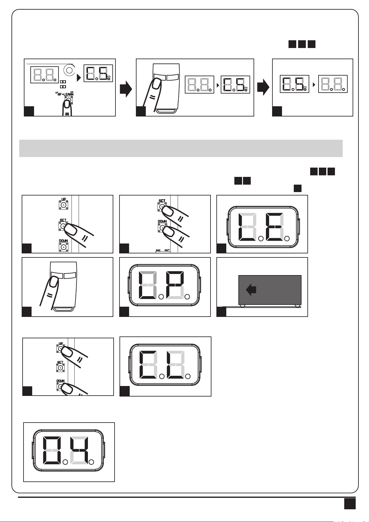
3.2 Transmitter Memorizing and Erasing Process
LED2
LED1
LED1
LED2
LED3
LED1
LED2
LED3
LED1
LED2
LED3
(1) Transmitter Memorizing: Press “RF Learn” button for 2 seconds, and the LED display shows “CS”; then press the transmitter
left button (A); the LED display will blink twice and then be off. The transmitter learning is completed.
(2) Erasing Memory: Press "RF Learn" button for 5~6 seconds as right LED display is on, then wait for LED display off.
A
B
LED display
ON
2 Sec
1 3
2
LED display
blink twice
1
LED display OFF
3
2
3.3 System Learning, Reset Process, and LED Display
! CAUTION: Before proceeding to system learning, the transmitter memorizing process has to be completed.
(1) To Complete the System Learning:
1 2
Step1: Press “SET”; then press “SET” + “DOWN” for 3 seconds, and the LED display shows “LE”
Step2: Press left button (A) on time, the LED display should show “LP”
Step3: The gate goes to Auto-learning, please wait for the learning process to be completed
4 5
6
3
Push
Press
3 Sec
1 2 3
A
B
Press
1~3 Sec
4 5 6
(2) To Reset Factory Setting:
Press UP and DOWN for 3 seconds, and the LED display shows “CL”
Push
3 seconds
1
(3) Motor current auto-detection
The LED display shows the current consumption of the motor
2
INSTRUCTIONS PL300E/PL400E/PL500E/PL800E SLIDING GATE OPENER USER MANUAL
"0.4" : During the system learning procedure, the control panel will automatically detect the
current consumption from each motor, indicate the resistance level of the gate whiling the
motor operation. If this reading increase instantly or stay in high reading, please check if
any object in between of the gate moving area, and contact your installer for inspection.
7
Page 10
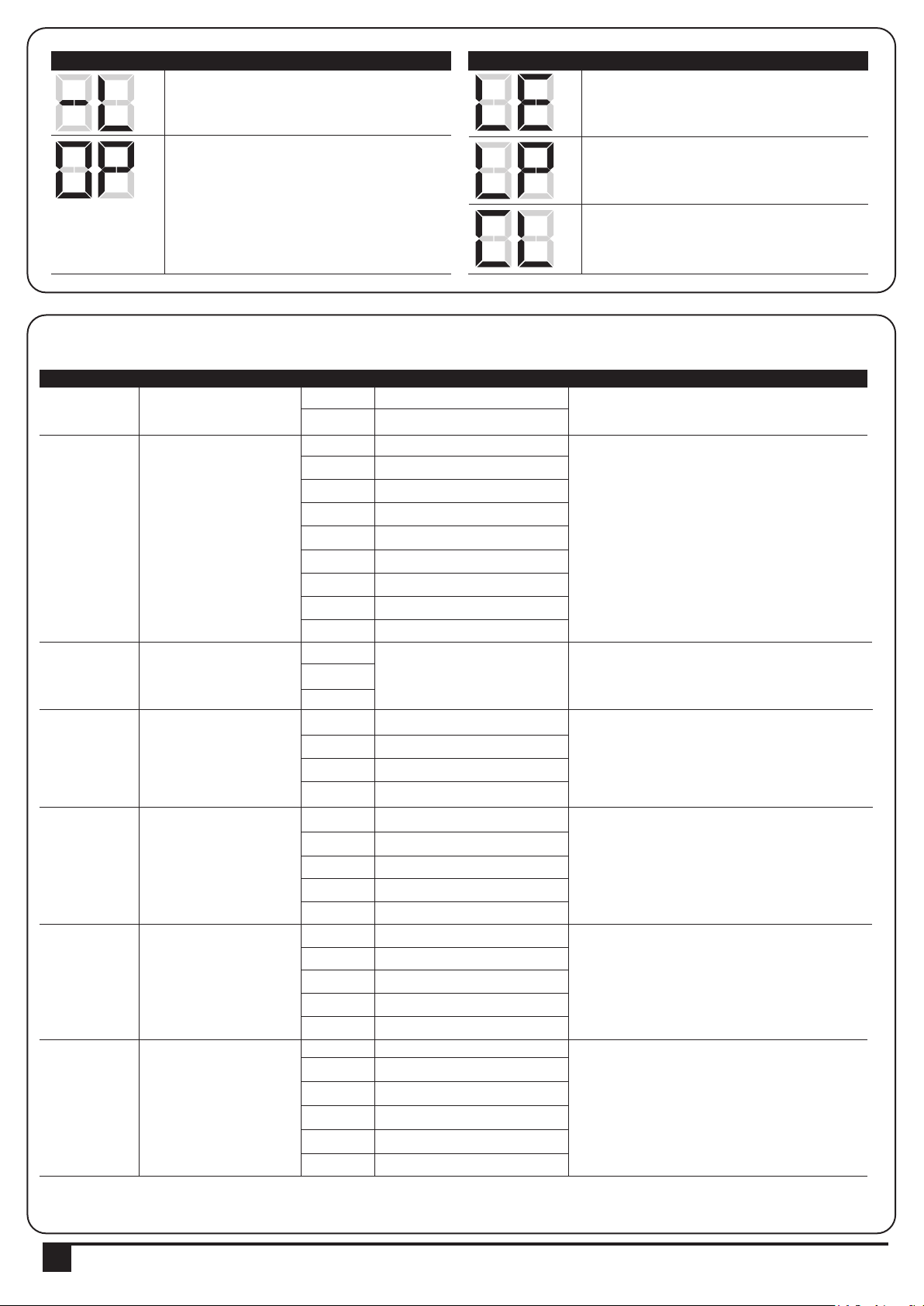
LED Display Programmable Functions LED Display Programmable Functions
“-L”: The system learning is not done. “LE”: Enter learning mode and then wait for
learning instructions.
“OP”: The system is in normal operation To
program, press SET button for 3 seconds,
when the LED display change from OP to 1,
press UP or DOWN to change function
settings (1 to P). Then press SET to enter the
sub function within each group, press UP or
“LP”: The system learning is in progress.
The Auto-learning process of gate moving:
“Gate open to the end- stop close to the
end- stop.”
“CL”: Reset Factory Setting.
Down to select sub functions and press SET
for confirmation.
3.4 Programmable Function Settings
LED Display Definition Function Value Description
1
2
3
4
5
6
7
Options ofGate
Opening direction
Automatic Closing
There actions of the
photocells / safety edge /
loop detector when they
detecting obstacles
Motor Speed
(% full speed)
The deceleration setting
for gate moving
Deceleration Speed
(% full speed)
Over current setting
1-1
1-2
2-0
2-1
2-2
2-3
2-4
2-5
2-6
2-7
2-8
3-1
3-2
3-3
4-1
4-2
4-3
4-4
5-1
5-2
5-3
5-4
5-5
6-1
6-2
6-3
6-4
6-5
7-1
7-2
7-3
7-4
7-5
7-6
Clockwise Opening
Counterclockwise Opening
No automatic closing
5 seconds
15 seconds
30 seconds
45 seconds
60 seconds
80 seconds
120 seconds
180 seconds
Please the function setting
after 8
50% Learning Speed
70% Learning Speed
85% Learning Speed
100% Learning Speed
75% of full distance
80%
85%
90%
95%
80%
60%
40%
25%
10%
2A
3A
4A
5A
6A
7A
1. The function can adjust the direction of gate opening.
2. The factory setting is "1-1".
1. This function can cause the gate toclose automatically
after the paused time.
2. The factory setting is "2-2”: 15 Secs as the pause time.
1. Please do the function setting after H & J
2. The factory setting is “3-1”.
1.The function can adjust the running speed of motor.
2.The factory setting is "4-4".
1. The factory setting is “5-1”.
1. The factory setting is “6-4”
1. The function can adjust the running force of motor to
be compatible with the gate weight.
2. The factory setting is "7-5".
8
INSTRUCTIONS PL300E/PL400E/PL500E/PL800E SLIDING GATE OPENER USER MANUAL
Page 11

LED Display Definition Function Value Description
8
9
A
C
E
F
H
J
L
P
Open Partially
(Pedestrian mode)
Pre-flashing
Over current reverse
setting
Open-stop-close-stop
function key
Open Partially function
key
External device control
function key
Photocell 1 function
Photocell 2 function
Emergency Stop Button
Remote Logic
8-1
8-2
8-3
8-4
8-5
8-6
9-0
9-1
A-0
A-1
A-2
A-3
C-1
C-2
C-3
C-4
E-0
E-1
E-2
E-3
E-4
F-0
F-1
F-2
F-3
F-4
H-0
H-1
J-0
J-1
L-0
L-1
P-1
P-2
3seconds
6seconds
9seconds
12seconds
15seconds
18seconds
The flashing light blinks when
the gate starts to move.
The flashing light blinks 3 seconds
before the gate starts to move.
Stop
Reverse 1 second
Reverse 3 second
Reverse to the end
A key
B key
C key
D key
No function in transmitter
A key
B key
C key
D key
No function in transmitter
A key
B key
C key
D key
Close
Open
Close
Open
Close
Open
Open-Stop-Close-Stop
Open-Stop-Close
1. The function can adjust the time of opening partially.
2. The factory setting is "8-2".
1. The factory setting is "9-0".
1. The factory setting is "A-3".
2. The reverse function only operate 3 times and then stop.
3. If gate reverses, the auto close function will be cancelled.
1. The factory setting is "C-1".
1. The factory setting is "E-2".
1. The factory setting is "F-3".
1. The factory setting is "H-0".
1. The factory setting is "J-0".
1. The factory setting is "L-0".
1. The factory setting is "P-1".
INSTRUCTIONS PL300E/PL400E/PL500E/PL800E SLIDING GATE OPENER USER MANUAL
9
Page 12
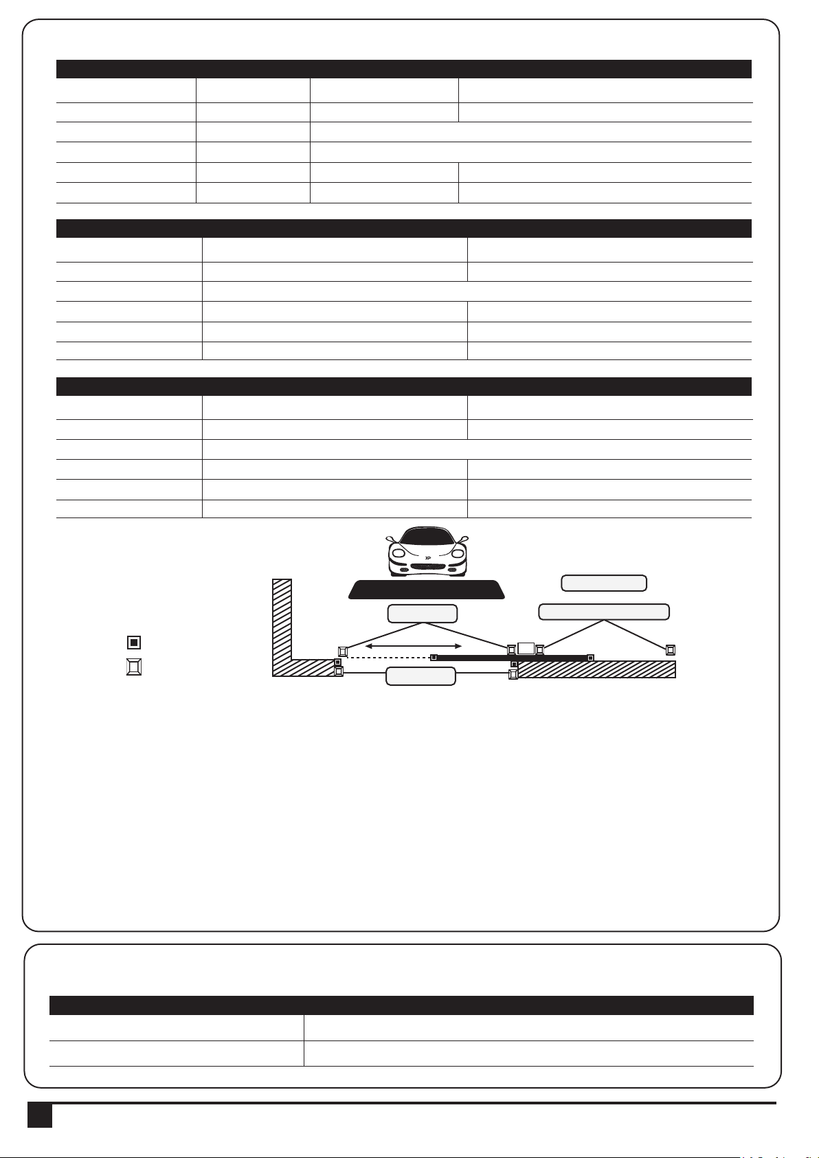
● F3 function settings:
Logic F3-1 The reactions of the photocells when detecting obstacles
Gate Status
Closed
Open
Stop during moving
Closing
Opening
Logic F3-2 The reactions of the safety edge/ photocell when detecting obstacles
Gate Status
Closed
Open
Stop during moving
Closing
Opening
Logic F3-3 The reactions of the loop detector/ photocell when detecting obstacles
Gate Status
Closed
Open
Stop during moving
Closing
Opening
Photocell 2
Stop opening
No effect
Stop opening
No effect
Closes the leaf
Safety Edge
Stop opening
Stop opening/ closing
Reverses to open for 2 seconds
Reverses to close for 2 seconds
Loop Detector
Open
Open
Open
Open
Photocell 1
No effect
Reloads automatic closing time
Reloads automatic closing time
Open
No effect
Reloads automatic closing time
Reloads automatic closing time
Locks and, on release, reverses to open
Locks and, on release, continues opening
Photocell 1/ Photocell 2
Stop opening
Photocell 1
No effect
Reloads automatic closing time
Open
No effect
Photocell 1
No effect
Reloads automatic closing time
Open
No effect
● The position of safety devices:
Photocell 1
or
Photocell 1 / Photocell 2
Safety Edge
Photocell
Loop Detector
Photocell 1
Photocell 2
3.5 Testing And Checking
Make sure the notices included in 1.1 General safety precaution “WARNINGS” has been carefully observed.
● Release the gearmotor with the proper release key.
● Make sure the gate can be moved manually during opening and closing phases with a force of max.
390N (40 kg approx.)
● Lock the gearmotor.
● Using the Key selector switch, push button device or the radio transmitter, test the opening, closing and
stopping of the gate and make sure that the gate is in the intended direction.
● Check the devices one by one (photocells, flashing light, key selector, etc.) and confirm the control unit
recognizes each device.
3.6 Recognition of LED
LED Indication Descriptions
LED1 Photocells
LED2 Photocells
10
LED1 will be on when the first pair of the photocells are activated.
LED2 will be on when the second pair of the photocells are activated.
INSTRUCTIONS PL300E/PL400E/PL500E/PL800E SLIDING GATE OPENER USER MANUAL
Page 13
4. Technical Characteristics:
4.1 Techanical Data Sheet Of Series
Motor
Gear type
Peak thrust
Nominal thrust
Engine RPM
Absorbed Power
Power supply
Nominal input power
Maximum gate weight
Maximum gate length
Maximum operating current
Operating Temperature
Dimension LxWxH mm.
Weight
Speed
PL300E PL400E
Worm Gear
3500N
3000N
3400RPM
72W
24 Vdc
3A
Up to 300 KG
4M
3A for Maximum 10 secs
o
C~+50oC
-20
250*170*275mm
7.5kg
24.25 cm/s
4.2 PH-2 Photocell Data Sheet
Detection type
Operating distance
Response time
Input voltage
Operating Temperature
Protection class
Dimension
Through beam
25 meters
100ms
AC/DC 12~24V
-20℃~+60℃
IP54
96mm * 45mm * 43mm
Worm Gear
4500N
4000N
3800RPM
100.8W
24 Vdc
4.2A
Up to 400 KG
5M
4A for Maximum 10 secs
o
C~+50oC
-20
250*170*275mm
8kg
27.10 cm/s
PL500E
Worm Gear
5500N
5000N
3800RPM
144W
24 Vdc
6A
Up to 500 KG
6M
5.5A for Maximum 10 secs
o
C~+50oC
-20
250*170*275mm
8kg
27.10 cm/s
PL800E
Worm Gear
7000N
2600 RPM
3800 RPM
120W
24 Vdc
6A
Up to 800 KG
8M
5.5A for Maximum 10 secs
o
C~+50oC
-20
250*170*275mm
9.5 kg
18.55 cm / sec
4.3 PR-1 Transmitter Data Sheet
Application
Frequency
Coding
Buttons
Power Supply
Operating Temperature
Dimension
Radio transmitter
433.92Mhz
Rolling code
2, for single-gate or dual-gate operation
3V with one CR2032 button type lithium battery
-20℃~+50℃
71.5mm * 33mm * 14mm
4.4 PF-1 Flashing Light Data Sheet
Application
Installation
Operating Temperature
Dimension
For outdoor use
Wall mounted vertically
-20℃~+50℃
85mm * 60.5mm * 40.5mm
4.5 PRB-1 External Receiver Box Data Sheet
Power Supply
Radio Frequency
Max. remote memorized
Dimensions
Output terminals
12V ~ 24V ac/dc
433.92Mhz
200pcs
106mm* 53mm* 20mm (L*W*H)
Output 1 & Output 2
INSTRUCTIONS PL300E/PL400E/PL500E/PL800E SLIDING GATE OPENER USER MANUAL
11
Page 14

5. Additional Information:
5.1. PHOTOCELL INSTALLATION GUIDE
The safety photocells are security devices for control automatic gates. Consist of one transmitter and one receiver
based in waterproof covers; it is triggered while breaking the path of the beams.
SPECIFICATION:
Detection Method
Sensing Range
Input Voltage
Response Time
Emitting Element
Operation Indicator
Dimensions
Output Method
Current Consumption Max
Water Proof
Through Beam
25M
AC/DC 12~24V
100MS
IR LED
Red LED(RX): ON(When Beam is Broken), Green(TX):ON
96*45*43mm
Relay Output
TX: 35MA/Rx: 38MA (When beam aligned properly);
TX: 35MA/ Rx: 20MA (When beam is broken)
IP54
Figure 4(1)
INSTALLATION:
Wire Connection of PH-2 Photocells See figure 4(2)
TX: Connect terminals 1 and 2 on the transmitter with the terminals Ph+ and GND on the P600B PCB.
RX: Connect terminals 1, 2 and 4 on the receiver with the terminals Ph+, GND and Ph1 on the P600B PCB.
And use an extra wire to connect terminals 2 and 5 on the receiver as a bridge.
Figure 4(2)
Lens
Beam Alignmnet
Indicator
Power Led
Indicator
1 2 3 4 5 1 2
Terminal Block
Power
Terminal Block
RX
Figure 4(3)
TX
1 2 3 4 5
1 2
RX
COM
N.C.
N.O.
GND
DC (12~24V)
TX
GND
DC (12~24V)
12
INSTRUCTIONS PL300E/PL400E/PL500E/PL800E SLIDING GATE OPENER USER MANUAL
Page 15

5.2 Wire Connection and Setting of PRB-1 External Reciever Box
RB1 Receiver Box
Orange
-Signal 1
Output 1 (Normally Open Relay)
Blue
Yellow
-GND
-Signal 2
Output 2 (Normally Open Relay)
Green
-GND
Red
-12V/24V
12V - 24V AC/DC
Black
-GND
1. Situation:
In order to use one 4 channel remote to operate with additional device besides the original gate automation system.
Install a receiver box to connect with the 2nd device (such as another Slider)
or the 3rd device (Such as garage automation system)
Original gate automation: Using Button A & B (Pedestrian Mode) on the remote to control gate opener
2nd device: Install an external receiver box, connect output 1 to the 2nd device (such as another Slider, shown as
below) use button C on the same remote to control the 2nd device
3rd device: install an external receiver box, connect the output 2 to the 3rd device (such as garage door), use the
Button D now to operate.
2. Wire Connection:
Orange
-Signal 1
Blue
Yellow
Green
Red
Black
-GND
-Signal 2
-GND
-12V/24V
-GND
9 10 11
Ph+
a. Orange cable (Signal 1) connect to terminal 10 (Pb) on the control board
b. Blue cable (GND) connect to terminal 11 (GND) on the control board
c. Red cable (12V/24V ac/dc) connect to terminal 9 (Ph+) on the control board
d. Black cable (GND) connect to terminal 11 (GND) on the control board
3. Device Testing & Remote Memorization
PRB-1 Receiver
Invalid Button
LED Light
Learn Button Test Button
Output 1
Invalid Button
a. After connect all necessary cables properly , press
Test Button to exam if the output 1 is working, the
gate opener should operate.
b. If Output 1 is functional, press and hold Learn Button
for 1 second, the LED light should be “ON”
* If the LED does not respond, please check the
cable connection again
c. Press and hold Button C on the remote for 1 second
after the LED is “ON”. The remote completed the
memorizing process when LED light turns “OFF”
GND
Pb
INSTRUCTIONS PL300E/PL400E/PL500E/PL800E SLIDING GATE OPENER USER MANUAL
13
Page 16

4. Memory Erasing
Press and hold learn button on the receiver box
for 10 seconds.
5. 4 Channel Transmitter Operation
Please refer to figure 5.2.1
PR-2
LED Light
Dual-gate
operation
gate openers
Output 1 operation
Figure 5.2.1
C
B
A
D
Output 2 operation
Single-gate
operation
gate openers
5.3 Green Box Installation Guide
Green Box is for purpose when gate opener is in standby mode to allow it enter the power saving mode.
Green Box
OFF ON
5+
AC out
Cable
AC in
Installation manner:
AC IN: connect the electricity
AC OUT: connect the power of gate opener, and connect the transformer
5V CABLE: connect 3 pins white socket of control board
Please make sure the switch of Green Box is off before proceeding the system learning and installation of device. Wait
for the system learning and installation of device to be completed, power on the Green Box
Gate opener will enter power saving mode without receiving any instruction in 1 min, and red LED light on Green Box
will be activated. Gate opener start the operation, red LED light and power saving mode will turn off.
CAUTION:
In case of loop or installation of photocell which need power consumption anytime, please do not install Green Box.
14
INSTRUCTIONS PL300E/PL400E/PL500E/PL800E SLIDING GATE OPENER USER MANUAL
34100-095-15-C
 Loading...