

Page 1
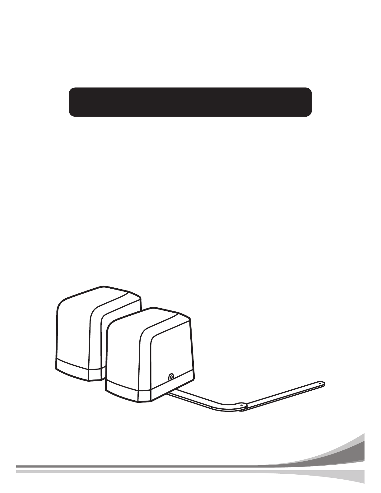
ARTICULATED ARM OPENERS
FOR RESIDENTIAL
USER MANUAL
24V DC GEAR MOTOR
PA250 USER MANUAL
Page 2
INDEX
1.1 Warnings
1.2 Installation
1.2.1 Standard Installation
1.2.2 Dimension Chart
1.2.3 Components of Installation
1.2.4 Installation of Articulated Arm Opener
1.2.5 Emergency Release
1.2.6 Photocell Installation
1.2.7 Green Box Installation
1.2.8 Power Supply Connections
2.1 Wiring Connection
2.1.1 Master Motor is installed at right side
2.1.2 Master Motor is installed at left side
2.2 LED Indication
2.3 Transmitter Memorizing and Erasing Process
2.4 System Learning Process
2.5 Gate Operation
2.6 Gate-moving Logic
2.7 Checking the Gate Movement
3. Function Setting
3.1 Function of the Led Display
3.2 Photocell Adjustment
3.3 Operations for Function Settings
3.4 Function Settings
4. Trouble Shooting
5. Technical Features
5.1 Dimension
5.2 Technical Feature
6. Maintenance
1
1
1
2
2
4
4
6
6
7
8
9
10
10
10
12
12
12
12
12
13
14
15
17
17
17
18
18
1.1 Warnings
Please read this instruction manual carefully before the installation of
gate-automated system.
This manual is exclusively for qualified installation personnel.
Manufacturer is not responsible for improper installation and failure to
comply with local electrical and building regulations.
Keep all the components of system and this manual for further
consultation.
In this manual, please pay extra attention to the contents marked by the
symbol:
Be aware of the hazards that may exist in the procedures of installation
and operation of the gate-automated system. Besides, the installation
must be carried out in conformity with local standards and regulations.
If the system is correctly installed and used following all the standards
and regulations, it will ensure a high degree of safety.
Make sure that the gates works properly before installing the
gate-automated system and confirm the gates are appropriate for the
application.
Do not let children operate or play with the gate-automated system.
Do not cross the path of the gate-automated system when operating.
Please keep all the control devices and any other pulse generator away
from children to avoid the gate-automated system being activated
accidentally.
Do not make any modifications to any components except that it is
mentioned in this manual.
Do not try to manually open or close the gates before you release the
gear motor.
If there is a failure that cannot be solved and is not mentioned in this
manual, please contact qualified installation personnel.
Do not use the gate-automated system before all the procedures and
instructions have been carried out and thoroughly read.
Test the gate-automated system weekly and have qualified installation
personnel to check and maintain the system at least every 6-month.
Install warning signs (if necessary) on the both sides of the gate to warn
the people in the area of potential hazards.
Page 3
ARTICULATED ARM OPENERS USER MANUAL
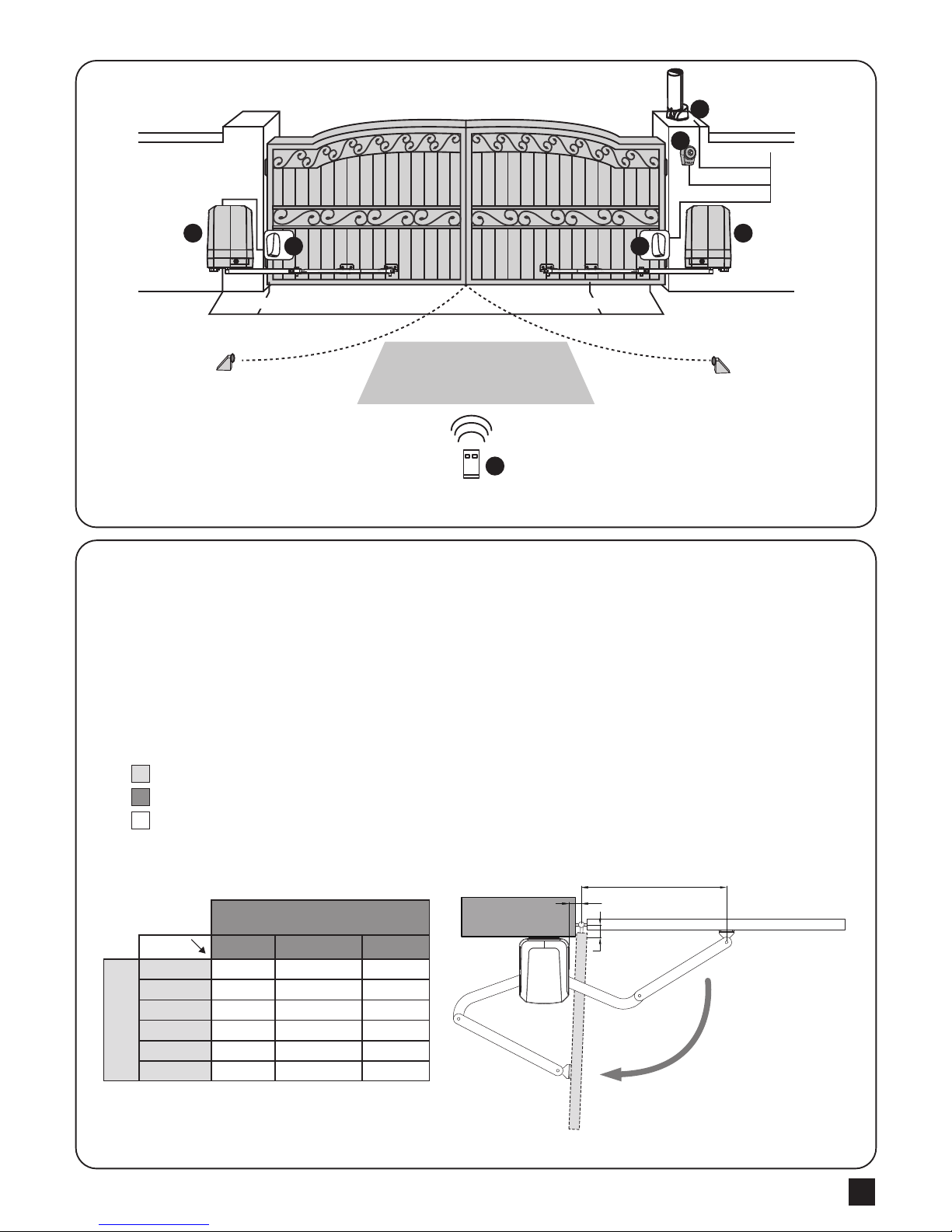
1.2.1 Standard Installation
1.2.2 Dimension Chart
1
1.2 Installation
2x1.5 mm
2
4x0.5 mm
2
TX - 4x0.5 mm
2
RX - 4x0.5 mm
2
2x1.5 mm
2
2x1.5 mm
2
4 4
2
33
1
5
1. 24V DC blinker with integrated antenna
2. Push Button
3. Photocells
4. 24V DC articulated arm opener
5. PR-1 Transmitter
Please comply with the measures shown on the chart for proper installation. If necessary,
please adjust the gate structure to the best operation.
Before starting the installation, please make sure that the gate moves freely and that :
1) Hinges are properly positioned and greased.
2) No any obstacle in the moving area.
3) No frictions between two gate leafs or and on the ground while moving.
4) Installation reference: to open the gate with 90 degree, please refer the data table below:
A: Distance between the gate hinge and the wall bracket.
B: Distance between the gate hinge and side face of the motor.
C: Distance between the gate hinge and the fixing point of the arm.
A
To open 90 degree.
C
B
C
50
100
150
200
250
300
unit: mm
A
B
50
625
615
600
585
565
540
100
575
565
550
535
515
/
150
545
540
/
/
/
/
M1 Master
Motor
M2 Slave
Motor
Page 4
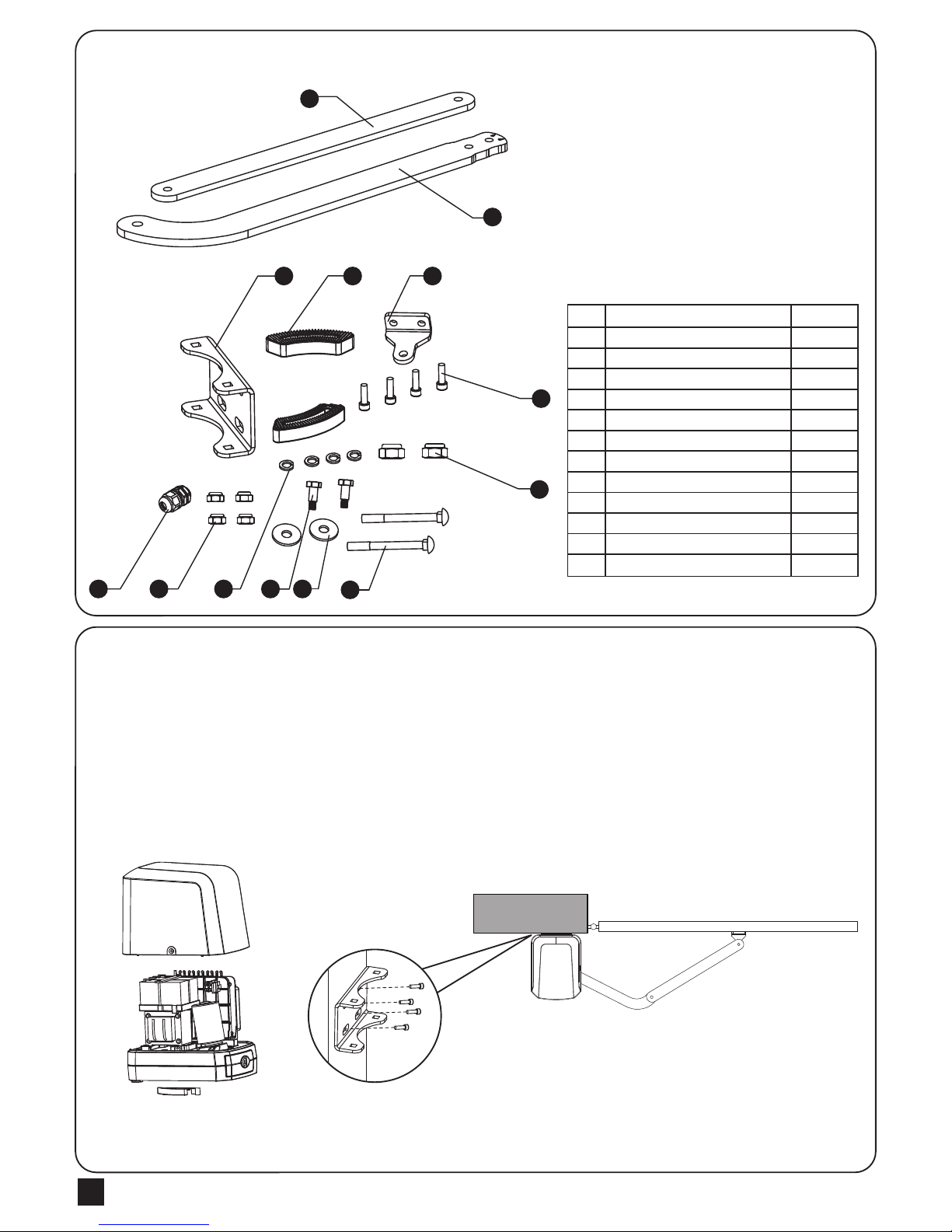
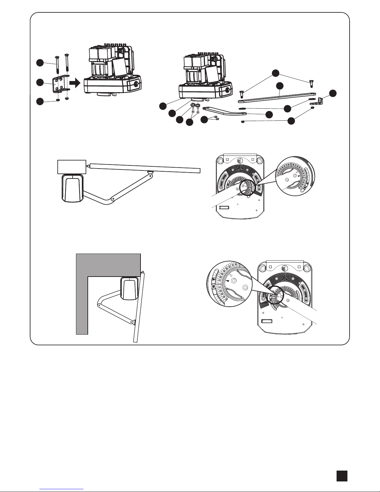
1.2.3 Components of Installation
1.2.4 Installation of Articulated Arm Opener
ARTICULATED ARM OPENERS USER MANUAL
2
1
2
3
4
5
6
7
8
9
10
11
12
13
Straight arm
Curved arm
U-shaped fixing plate
Mechanical stopper
Front-end fixing bracket
Screw
Nut Ø10
Screw
Gasket
Screw
Spring washer
Nut Ø8
Cable gland
1 pce
1 pce
1 pce
2 pcs
1 pce
4 pcs
2 pcs
2 pcs
2 pcs
2 pcs
4 pcs
4 pcs
1 pce
2
3 4 5
6
7
8
13 12 11 10 9
1
1. Refer to the Dimension Chart to choose the correct dimensions of the motors and
position to be installed.
2. Check if the mounting surface of the brackets to be installed is smooth, vertical and rigid.
3. Arrange the cables for power supply cable of the motors.
4. Motor installation and setting for mechanical stopper in opened and closed position.
2) Place the gate in the full closed position and
fix the U-shaped fixing plate on the wall.
1) Remove the upper cover and mechanical
stoppers on the bottom of motor.
Page 5
ARTICULATED ARM OPENERS USER MANUAL
3
4) After positioning the front of curved arm on the bottom of motor,
release the motor and position the minor arm on the end of
curved arm and mounting bracket with corresponding screws
and nuts.
5) Closed position adjustment :
4.1 After the full closed position decided, fix the corresponding mechanical stopper at the position.
4.2 After the full closed position decided, make the pointer on limit switch aligned with the pointer on the curved arm.
(Red points shown on the figure below indicate the pointers)
6) Opened position adjustment :
5.1 Adjust the gate to full opened position and after the position decided, fixed with corresponding mechanical stopper.
5.2 Adjust the gate to full opened position and after the position decided, make the pointer on the electromechanical
limit switch aligned with the pointer on the curved arm. (Red points shown on the figure below indicate the pointers)
1
5
2
7
6
3
8
12
3) Install the motor on the U-shaped fixing
plate with corresponding screws and nuts.
12
9
10
4
13
11
Page 6
ARTICULATED ARM OPENERS USER MANUAL
4
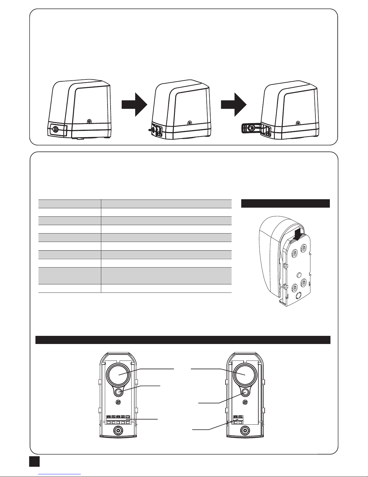
1.2.5 Emergency Release
1) Insert the release key to the release slot
2) Turn the release key anti-clockwise
3) Pull out the release bar
4) Turn the release key clockwise to fix the release bar, the release bar has to be in pulled out position when turning
the release key clockwise
The safety photocells are security devices for control automatic gates. Consist of one transmitter and one receiver
based in waterproof covers; it is triggered while breaking the path of the beams.
INSTALLATION:
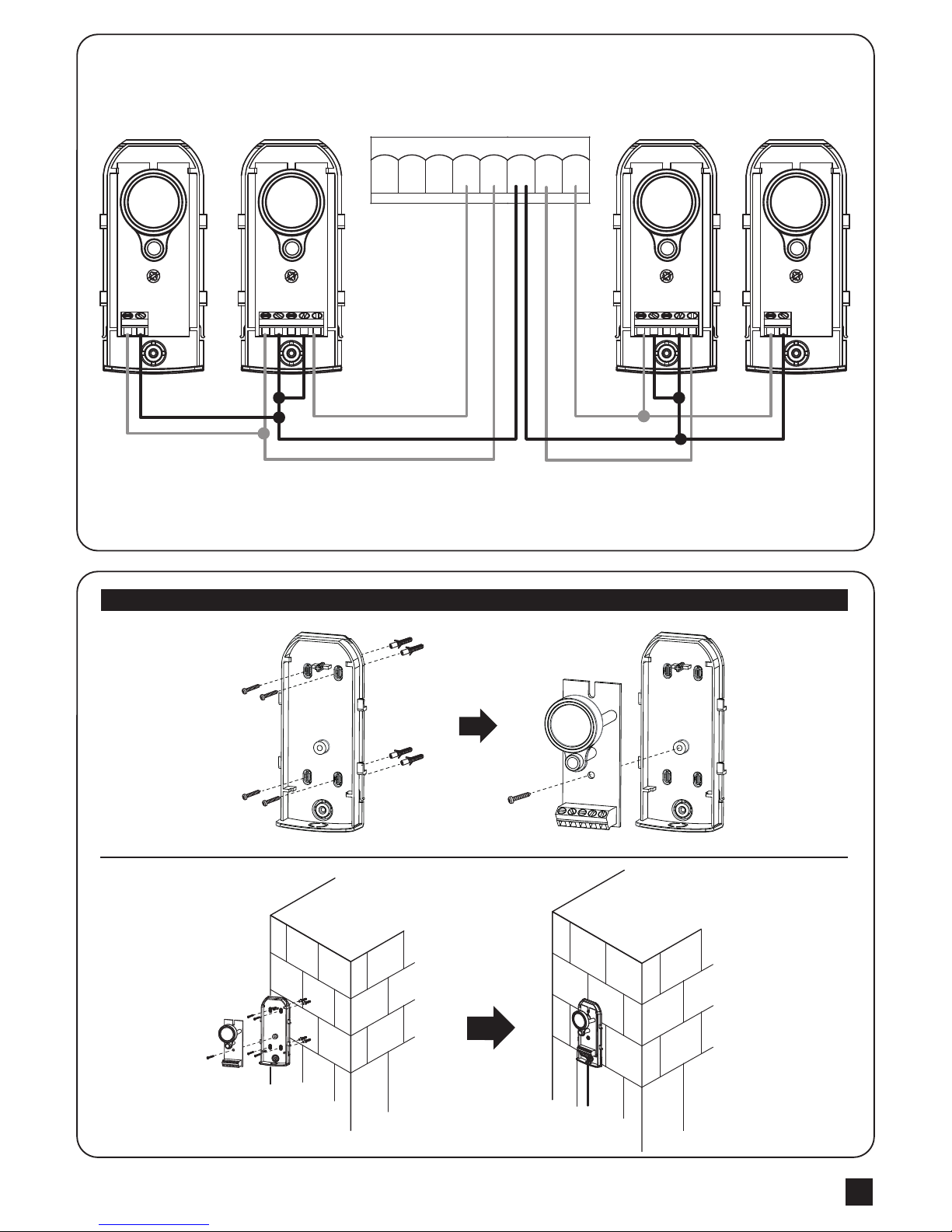
Wire Connection of Photocells
TX: Connect terminals 1 and 2 on the transmitter with the terminals GND and PhVcc on the PC190 PCB.
RX: Connect terminals 1,2 and 4 on the receiver with the terminals GND, PhVcc, and Ph1/Ph2 on the PC190 PCB.
And use an extra wire to connect terminals 2 and 5 on the receiver as a bridge.
Detection Method
Sensing Range
Input Voltage
Response Time
Emitting Element
Operation Indicator
Dimensions
Output Method
Current Consumption Max
Water Proof
Through Beam
25M
AC/DC 12~24V
100MS
IR LED
Red LED(RX): ON(When Beam is Broken), Green(TX):ON
96*45*43mm
Relay Output
TX: 35MA/Rx: 38MA (When beam aligned properly);
TX: 35MA/ Rx: 20MA (When beam is broken)
IP54
SPECIFICATION:
Figure 1(2)
Figure 1(1)
1.2.6 Photocell Installation
RX
Lens
Beam Alignmnet
Indicator
Power Led
Indicator
Terminal Block
Power
Terminal Block
TX
1 2 3 4 5 1 2
Page 7
ARTICULATED ARM OPENERS USER MANUAL
5
Figure 1(3)
SKey Ph2Ph1 PhVcc PhVccDKey GND GND
19 20 21 22 23 24 25 26
1 2 3 4 5
COMNCNO+
-
+
-
1 2
RX1TX1
1 2 3 4 5
COMNCNO+
-
+
-
1 2
RX2 TX2
Page 8
ARTICULATED ARM OPENERS USER MANUAL
6
Please kindly notice that the operation of power connection should be carried out by a qualified electrician with
following steps:
1). Make sure the gearmotor is not connected to the power supply before the installation is done.
2). Make sure all the wires are firmly connected.
3). Supply the gearmotor with the power.
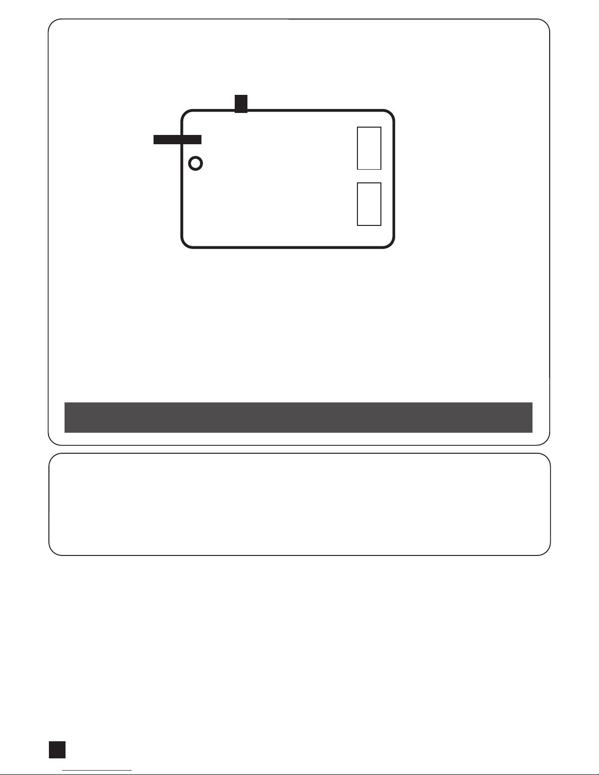
OFF ON
Green Box
5+
Cable
AC out
AC in
Green Box is for purpose when gate opener is in standby mode to allow it enter the power saving mode.
Installation manner:
AC IN: connect the electricity
AC OUT: connect the power of gate opener, and connect the transformer
5V CABLE: connect 3 pins white socket of control board
Please make sure the switch of Green Box is off before proceeding the system learning and installation of device.
Wait for the system learning and installation of device to be completed, power on the Green Box
Gate opener will enter power saving mode without receiving any instruction in 1 min, and red LED light on Green Box
will be activated. Gate opener start the operation, red LED light and power saving mode will turn off.
CAUTION:
In case of loop or installation of photocell which need power consumption anytime, please do not install Green Box.
1.2.7 GREEN BOX INSTALLATION
1.2.8 POWER SUPPLY CONNECTIONS
Page 9
ARTICULATED ARM OPENERS USER MANUAL
7
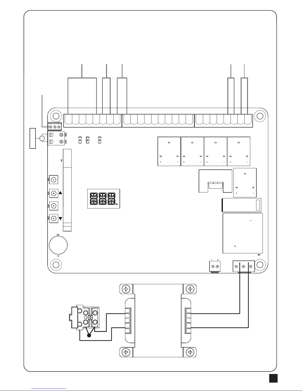
2.1 Wiring Connection
Figure 2(1)
Key
Selector
Push
Button
Photocells connection is
detailed on page 5
Flashing
LightLatch
Transformer
Antenna
Green Box
LED Display
Blue LED – RF Learning
LED2 Push button or Key selector
LED3 Photocell 1
LED 4 Photocell 2
UP
SET
SET
DOWN
RF-LEARN
RF-LEARN
LED2LED4LED3
11
Lit+Lit-Lat+Lat-M1+M1-M2+M2-5VS1S2GNDLmt1Lmt2GNDLmt3Lmt4GNDGND Ph1Ph2 PhVccPhVcc GND DKeySKey
26 2425 23 2122 1920 18 1617 15 1314 11 1012 9 8 67 5 34 12
Page 10

ARTICULATED ARM OPENERS USER MANUAL
8
M1+ M1-
Motor1 Power
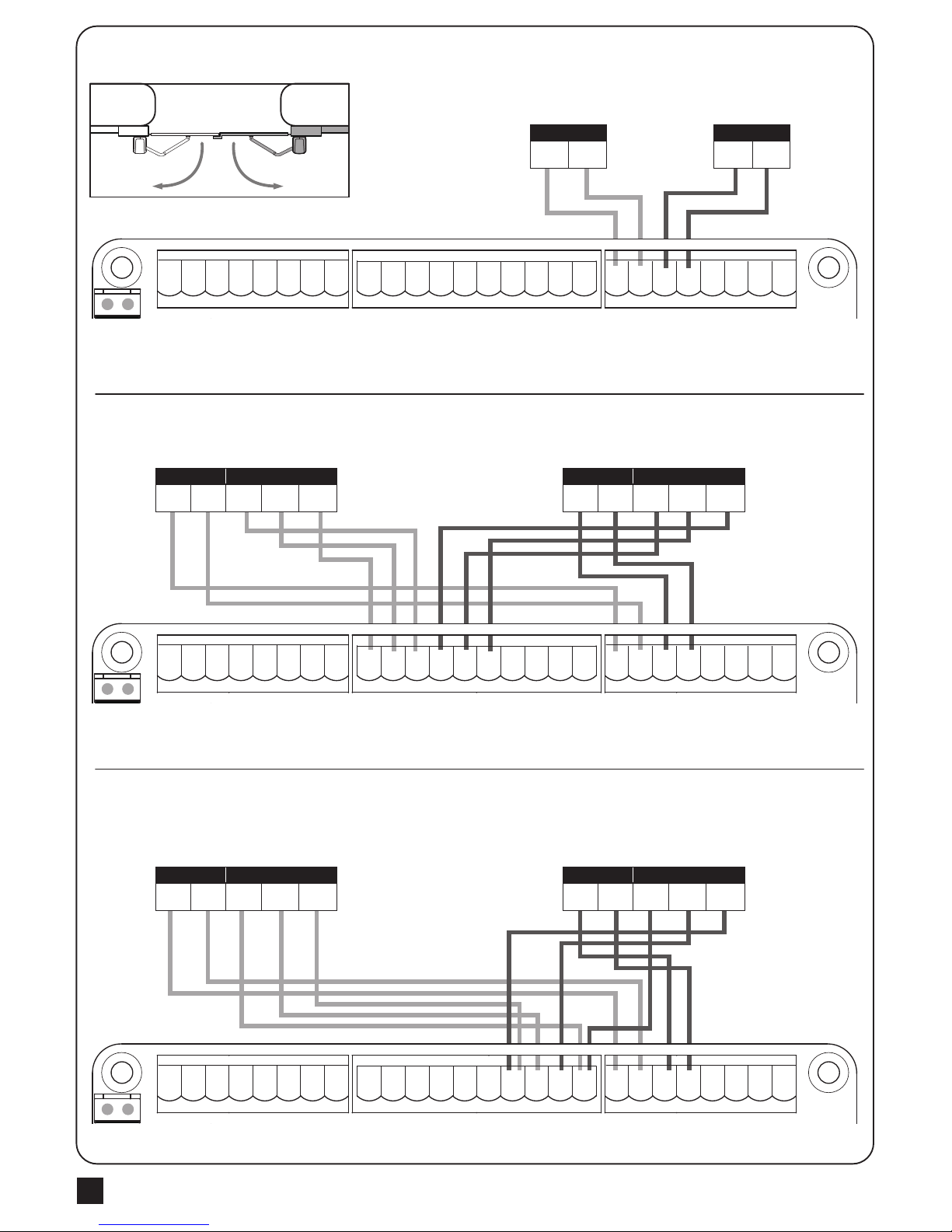
2.1.1 Master Motor is installed at right side
Motor with Hall sensor
M2-M1-
Lat-
Lit-
Lmt4Lmt3
Lmt2
Lit+ SKey
S1
M2+
M1+Lat+ Ph2Ph1 PhVcc PhVcc
S25V
ANT
GND
DKey GND
GND
GND
GND
Lmt1
GND
J5
J4 J3
J8
CO
CO
CO
CO
1 2 3 4 5 6 7 8
9 10 11 12 13 14 15 16 17 18
19 20 21 22 23 24 25 26
LED2
LED3
LED4
M2+ M2-
Motor2 Power
Motor with Limit switch
M2-M1-
Lat-
Lit-
Lmt4Lmt3
Lmt2
Lit+ SKey
S1
M2+
M1+Lat+ Ph2Ph1 PhVcc PhVcc
S25V
DKey GND
GND
GND
GND
Lmt1
GND
J5
J4 J3
J8
1 2 3 4 5 6 7 8
9 10 11 12 13 14 15 16 17 18
19 20 21 22 23 24 25 26
M1- Limit1 Limit2 GNDM1+
Motor1 Power Limit Switch
M2- Limit4 Limit3 GNDM2+
Motor2 Power Limit Switch
M2-M1-
Lat-
Lit-
Lmt4Lmt3
Lmt2
Lit+ SKey
S1
M2+
M1+Lat+ Ph2Ph1 PhVcc PhVcc
S25V
DKey GND
GND
GND
GND
Lmt1
GND
J5
J4 J3
J8
1 2 3 4 5 6 7 8
9 10 11 12 13 14 15 16 17 18
19 20 21 22 23 24 25 26
M1- 5V S1 GNDM1+
Motor1 Power Hall sensor
M2- 5V S2 GNDM2+
Motor2 Power Hall sensor
Figure 2(2)
Figure 2(3)
Figure 2(4)
Remark:
Limit1, Limit3 (Open limit)
Limit2, Limit4 (Close limit)
M1 M2
Page 11
ARTICULATED ARM OPENERS USER MANUAL
9
M2+ M2-
Motor2 Power
M1+ M1-
Motor1 Power
M2- Limit4 Limit3 GNDM2+
Motor2 Power Limit Switch
M2- 5V S2 GNDM2+
Motor2 Power Hall sensor
M2-M1-
Lat-
Lit-
Lmt4Lmt3
Lmt2
Lit+ SKey
S1
M2+
M1+Lat+ Ph2Ph1 PhVcc PhVcc
S25V
DKey GND
GND
GND
GND
Lmt1
GND
J5
J4 J3
J8
1 2 3 4 5 6 7 8
9 10 11 12 13 14 15 16 17 18
19 20 21 22 23 24 25 26
M2-M1-
Lat-
Lit-
Lmt4Lmt3
Lmt2
Lit+ SKey
S1
M2+
M1+Lat+ Ph2Ph1 PhVcc PhVcc
S25V
DKey GND
GND
GND
GND
Lmt1
GND
J5
J4 J3
J8
1 2 3 4 5 6 7 8
9 10 11 12 13 14 15 16 17 18
19 20 21 22 23 24 25 26
M1- Limit1 Limit2 GNDM1+
Motor1 Power Limit Switch
M2-M1-
Lat-
Lit-
Lmt4Lmt3
Lmt2
Lit+ SKey
S1
M2+
M1+Lat+ Ph2Ph1 PhVcc PhVcc
S25V
DKey GND
GND
GND
GND
Lmt1
GND
J5
J4 J3
J8
1 2 3 4 5 6 7 8
9 10 11 12 13 14 15 16 17 18
19 20 21 22 23 24 25 26
M1- 5V S1 GNDM1+
Motor1 Power Hall sensor
Figure 2(5)
Figure 2(6)
Figure 2(7)
Remark:
Limit1, Limit3 (Close limit)
Limit2, Limit4 (Open limit)
2.1.2 Master Motor is installed at left side
Motor with Hall sensor
Motor with Limit switch
M1M2
Page 12

ARTICULATED ARM OPENERS USER MANUAL
10
2.4 System Learning Process
2.3 Transmitter Memorizing and Erasing Process
(A) Transmitter Memorizing: Press and hold the “RF-LEARN” button on the PCB for 1 second and then the blue LED
indicator on the RF board will be “ON”. Press A button for dual-gate installation ; press B button for single-gate
installation on the transmitter within 5 seconds. The transmitter learning is completed
when the blue indicator is “OFF”.
(B) Transmitter Memory Erasing: Press and hold the “RF-LEARN” button on the PCB for 10 seconds until blue LED off.
(C) One radio receiver can be memorized with 200pcs of transmitters.
Blue LED on receiver board: Blinks three times when remote learning is completed.
LED2 External device : If the switch of the key selector, or the push button is activated, LED2 will be on.
LED3 Photocells 1 : LED3 will be on when the first pair of the photocells are activated.
LED4 Photocells 2 : LED4 will be on when the second pair of the photocells are activated.
Antenna
M2-M1-
Lat-
Lit-
Lmt4Lmt3
Lmt2
Lit+ SKey
S1
M2+
M1+Lat+ Ph2Ph1 PhVcc PhVcc
S25V
ANT
GND
DKey GND
GND
GND
GND
Lmt1
GND
PC190-PCB1
40121-377-A1
+ -
T4
SW3
UP
Q17
J5
SW1
RF-LEARN
RF1
K5
K3
K2K1
J4 J3
J7
F1
DB1
J8
SW4
SET
SW5
DOWN
NC NO
CO
+-
NC NO
CO
+-- +
CO
NONC
- +
CO
NONC
NC NO
CO
+-
-
+
1 2 3 4 5 6 7 8
9 10 11 12 13 14 15 16 17 18
19 20 21 22 23 24 25 26
LED2
LED3
LED4
2.2 LED Indication
Step1: Connect the master motor wires to M1 terminals and the slave motor wires to M2 terminals correctly.
If only one gate is installed, the motor wires have to be connected to M1 terminals.
Step2: Set the function F2-1 for dual gate learning; or set the function F2-2 for single gate learning.
Step3: To start dual gate system learning.
To start dual gate system learning.
Press and hold the “UP+SET+DOWN” button on the PCB for 3 seconds. The LED display will show “LEA” and
“D-G”. Press the button (A) on the transmitter within 10 seconds to activate the system learning automatically.
LED display will show “ARN”, do not interrupt this procedure by pressing the transmitter or stop the gate. In
system learning mode, the gates will proceed with the following procedures figure 2(8). LED display will show
“RUN” once system learning completed.
To start single gate system learning.
Press and hold the “UP+SET+DOWN” button on the PCB for 3 seconds. The LED display will show “LEA” and
“S-G”. Press the button (B) on the transmitter within 10 seconds to activate the system learning automatically.
LED display will show “ARN”, do not interrupt this procedure by pressing the transmitter or stop the gate. In
system learning mode, the gates will proceed with the following procedures figure 2(8). LED display will show
“RUN” once system learning completed.
Page 13

ARTICULATED ARM OPENERS USER MANUAL
11
A. Dual Gate:
Slave Gate Close → Master Gate Close → Master Gate Open → Slave Gate Open →
Slave Gate Close → Master Gate Close
B. Single Gate :
Master Gate Close → Master Gate Open → Master Gate Close
1
1
5
2 3
1 2 3
4
6
2 3
1 2 3
4 5 6
Notes:
(A) System learning fails and needs to be learned again when an unpredictable interruption occurs.
(B) Once the system learning is completed, there is no need to proceed with the learning process again when there isa
power failure.
(C) The slave gate opens 3 seconds after the master gate opens and the master gate closes 3 seconds after the slave
gate closes.
(D) While using limit switch mode, please make sure the motor hit limit switch when it’s in deceleration speed.
figure 2(8)
Page 14

ARTICULATED ARM OPENERS USER MANUAL
12
2.5 Gate Operation
Press the button “A” on the transmitter for dual-gate operation.
Press the button “B” on the transmitter for single-gate
operation in either single-gate or dual-gate installation.
2.6 Gate-moving Logic
(A) In gate-opening phase: The gates stop if the transmitter/push button/key selector is activated, and close when
the transmitter/push button/key selector is reactivated.
(B) In gate-closing phase: The gates stop if the transmitter/push button/key selector is activated, and open when
the transmitter/push button/key selector is reactivated.
(C) In gate-opening or gate-closing phase: For safety purpose, the gates stop if encountering obstacles.
2.7 Checking the Gate Movement
1). Release the gearmotor with the release key and move the gate to the middle so that it is free to move in both
opening and closing directions; then lock the gearmotor.
2). Perform the gate opening and closing several times and make sure the gates reaches the limit switch at least
2~3 centimeters before the mechanical stop.
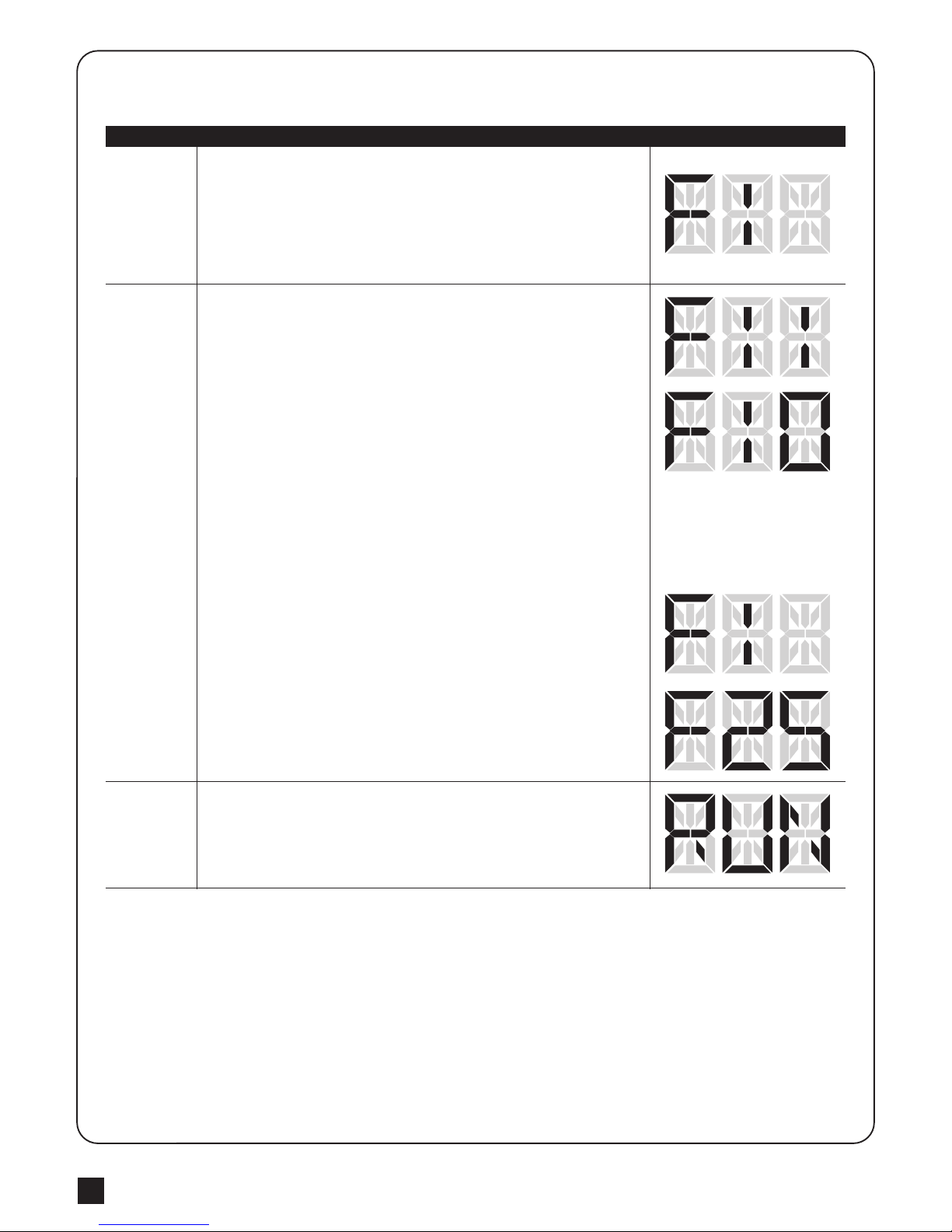
3.1 Function Of The Led Display
3. Function Setting
LED Display Programmable Functions
“N-L”: The system learning is not done.
“RUN”: The system is in normal performing.
“CLN” The memory of the system is all cleaned/deleted. Press and hold “UP+DOWN” for
5 seconds.
“STP”: The motor stop in the middle of the operating process.
“ME”: Motor operation error
“LEA”: Enter learning mode and then wait for learning instructions.
The operation of gate learning:
(1). Press “SET” + “DOWN” + “UP” for 3seconds, and the LED display shows “LEA” +”DG”;
and then press the transmitter (A) button one time. After 1~3seconds, the LED display shows
the current value during learning mode, it shows 10 for 1A.
A
B
C
D
Page 15
ARTICULATED ARM OPENERS USER MANUAL
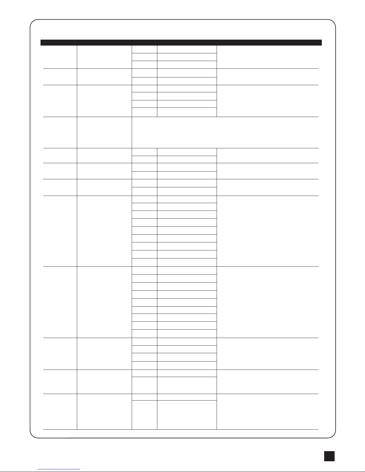
13
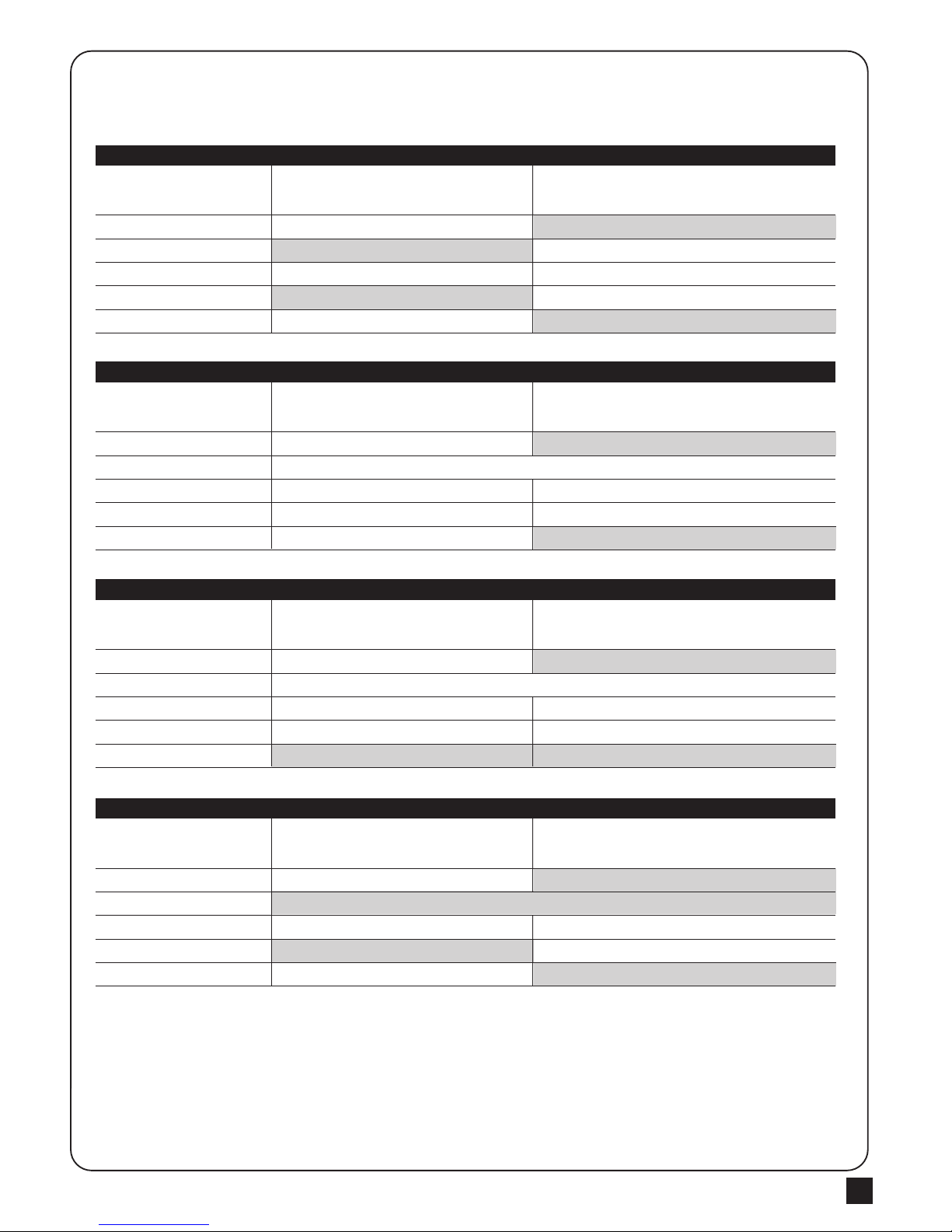
1. F9-1
Type of Safety Device
FULLY CLOSED
FULLY OPENED
STOP DURING MOVING
CLOSING
OPENING
Safety Device2 :
Photocell-OPEN
Open not allowed
No effect
Open not allowed
No effect
Close
Safety Device1 :
Photocell-CLOSE
No effect
Reload automatic closing time
Reload automatic closing time
Open
No effect
Position of Gate When safety devices are activated
2. F9-2
Type of Safety Device
FULLY CLOSED
FULLY OPENED
STOP DURING MOVING
CLOSING
OPENING
Safety Device2 :
Safety Edge
Open not allowed
Locks
Reverse to open for 2 seconds
Reverse to clsoe for 2 seconds
Reload automatic closing time
Safety Device1 :
Photocell-CLOSE
No effect
Reload automatic closing time
Open
No effect
Position of Gate When safety devices are activated
3. F9-3
Type of Safety Device
FULLY CLOSED
FULLY OPENED
STOP DURING MOVING
CLOSING
OPENING
Safety Device2 :
Opening Device
Open
Open
Open
No effect
Reload automatic closing time
Safety Device1 :
Photocell-CLOSE
No effect
Reload automatic closing time
Open
No effect
Position of Gate When safety devices are activated
4. F9-4
Type of Safety Device
FULLY CLOSED
FULLY OPENED
STOP DURING MOVING
CLOSING
OPENING
Safety Device2 :
Photocell-OPEN/CLOSE
Open not allowed
Locks
Stop
Stop
Close not allowed, Open for 2 seconds when auto closing is ON
Safety Device1 :
Photocell-CLOSE
No effect
Close not allowed
Open
No effect
Position of Gate When safety devices are activated
3.2 Photocell Adjustment
The actions of the photocells safety edge loop detector when they detecting obstacles.
Page 16
ARTICULATED ARM OPENERS USER MANUAL
14
For exmple: How to set the function “F1-0”; the steps are following:
(1) Press the “SET” button for 3seconds then releases it, and the
system enters the first option. The LED will display “F1” (*) as the
right hand-side picture.
(*) If you would like to enter “F2” function or others as the first option,
please press the “UP” button to adjust F2~F8 until you get “F2”.
1.
3.3 Operations for Function Settings
Step Operations LED Display after the Step
(2) After completing the operation (1), then press the “SET” button
again, you will enter the second option as the right hand-side picture.
And you will see the third number for the second option.
(3) Continually press the “Down” button until you search the function
“0” (**) of F1 as the right hand-side picture. “F1-0” is set completely.
(**) If you would like to set one of functions “0 ~ 8” as the second
option, please press the “UP” or “Down” button to adjust it.
(4) If you would continue setting up the next functions, please press
“SET” to return the first option, like F1 or F2 or F3…or F8.
For example, after complete “F1-0” setting. You would continue
setting “F2-5”, please press “SET” to return the formal option. The
LED display shows the first two numbers as as the first option as the
right hand-side picture, “F1”. And then follow the operation (*) and (2)
~ (3) until you get “F2-5” as the right hand-side picture. “F2-5” is set
completely.
After setting all functions you need, then wait for 10seconds, the LED
will display “RUN”. And you can use transmitter to operate the gate.
2.
3.
Page 17
ARTICULATED ARM OPENERS USER MANUAL
15
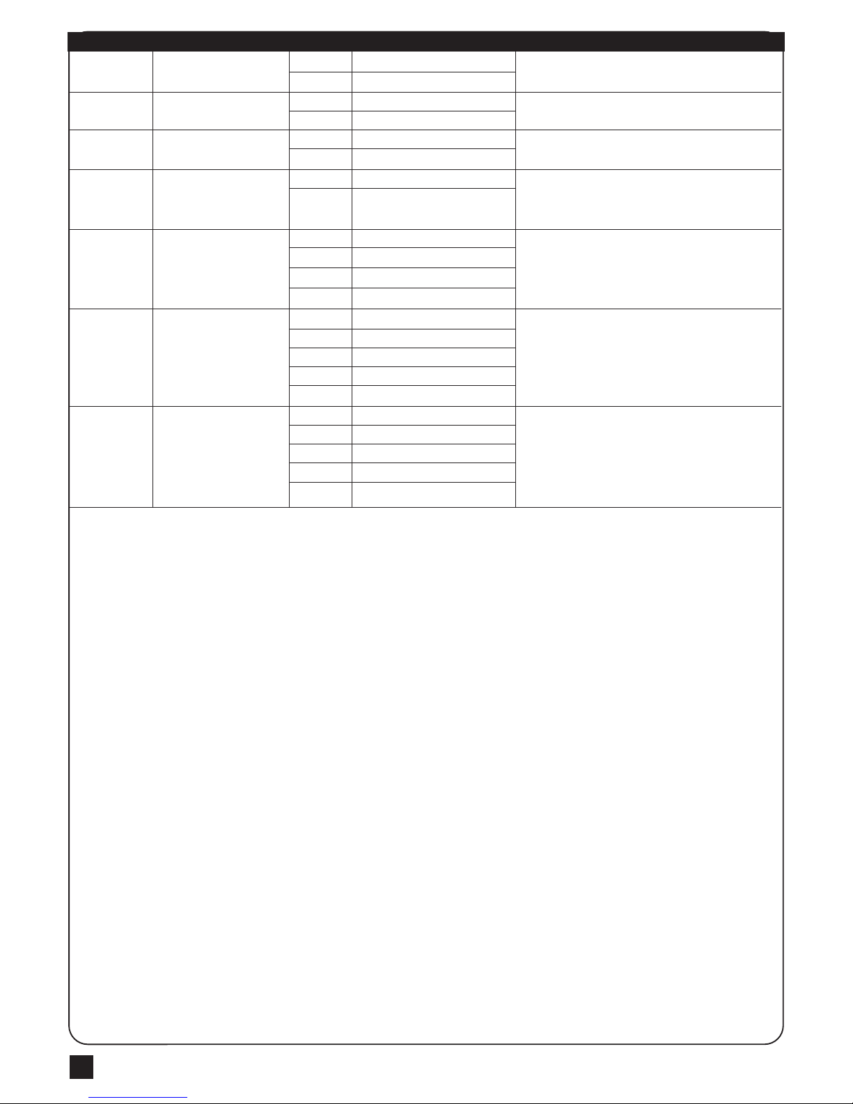
3.4 Function Settings
Note(F3 Setting is for F1-3 Motor with Hall sensor):
Only in “F1-3”Hall sensor mode, the PCB will record all the current value while learning mode. Please set F3 function
after learning mode. The LED display 10 to indicate all of the recorded values will increase 1 ampere as the over current
value. In other words, the LED shows 20 to indicate all the recorded values will increase 2 ampere as the over current
value. The value can be adjusted by pressing button UP and DOWN. The maximum value is 40(4.0A) and the minimum
value is 05(0.5A).
LED Display Definition Parameter Table Description
Motor Type
Dual or Single Gate
Over Current Setting
Over Current Setting
Operation Speed
Deceleration function
Deceleration Speed
Open/Close delay of dual
gate operation adjustment
Auto-Close adjustment
Photocell function mode
Pedestrian Mode function
Pre-Flashing function
F1
F2
F3
F3
F4
F5
F6
F7
F8
F9
FA
FB
F1-1
F1-2
F1-3
F2-1
F2-2
F3-1
F3-2
F3-3
F3-4
F4-1
F4-2
F5-1
F5-2
F6-1
F6-2
F7-1
F7-2
F7-3
F7-4
F7-5
F7-6
F7-7
F7-8
F7-9
F8-0
F8-1
F8-2
F8-3
F8-4
F8-5
F8-6
F8-7
F8-8
F9-1
F9-2
F9-3
F9-4
FA-0
FA-1
FB-0
FB-1
Motor only
Motor with Limit Switch
Motor with Hall sensor
Dual Gate
Single Gate
2A
3A
4A
5A
100% Full speed
80% Full speed
Function ON
Function OFF
70% Full speed
50% Full speed
2 sec
3 sec
4 sec
5 sec
6 sec
7 sec
8 sec
9 sec
10 sec
Function OFF
3 sec
10 sec
20 sec
40 sec
60 sec
120 sec
180 sec
300 sec
Mode 1
Mode 2
Mode 3
Mode 4
Function OFF
Function ON
Function OFF
Function ON
1. The factory setting is "F1-1".
1. The factory setting is "F2-1".
1. The factory setting is "F3-1",
2. F3 setting is for F1-1 Motor only and F1-2 Motor with
Limit Switch
1. The factory setting is "F4-1".
1. The factory setting is "F5-1".
1. The factory setting is "F6-2".
1. The factory setting is "F7-1".
1. Auto-close mode activates when the gates move to
the end position or stopped manually. If the transmitter,
push button, or the key selector is activated before the
auto-close counting, the gate will close immediately.
2. The factory setting is "F8-2".
1. The factory setting is "F9-1".
1. When funciton on and push B key in the transmitter,
one gate will open partically.
2. The factory setting is "FA-1".
1. When function ON, the light will flash before the gate
operate 3 seconds. If set OFF, the flash light will operate
with motor in the same time.
2. The factory setting is "FB-0".
Page 18
ARTICULATED ARM OPENERS USER MANUAL
16
LED Display Definition Function Table Description
Photocell 1 function
Photocell 2 function
Buzzer function
Latch release function
Open/Stop/Close/Stop
function key
Pedestrian Mode function key
Auto-Close function Key
FC
FD
FE
FF
FG
FH
FI
FC-0
FC-1
FD-0
FD-1
FE-0
FE-1
FF-0
FF-1
FG-1
FG-2
FG-3
FG-4
FH-0
FH-1
FH-2
FH-3
FH-4
FI-0
FI-1
FI-2
FI-3
FI-4
Function OFF
Function ON
Function OFF
Function ON
Function OFF
Function ON
Function OFF
Function ON
A Key
B Key
C Key
D Key
Function OFF
A Key
B Key
C Key
D Key
No key to control
A Key
B Key
C Key
D Key
1. The factory setting is "FC-0".
1. The factory setting is "FD-0".
1. The factory setting is "FE-1".
1. If the function on, the gate will move forword a little before the
gate operate for releasing the latch.
2. The factory setting is "FF-1".
1. The factory setting is "FG-1".
1. The factory setting is "FH-2".
1. The key is to turn on or off the Auto-Close function.
2. The factory setting is "FI-3".
3.When the flasher and buzzer is running, the auto closed
button has no function till flasher and buzzer finish running.
Page 19

ARTICULATED ARM OPENERS USER MANUAL
17
5. Technical Features
5.1 Dimension
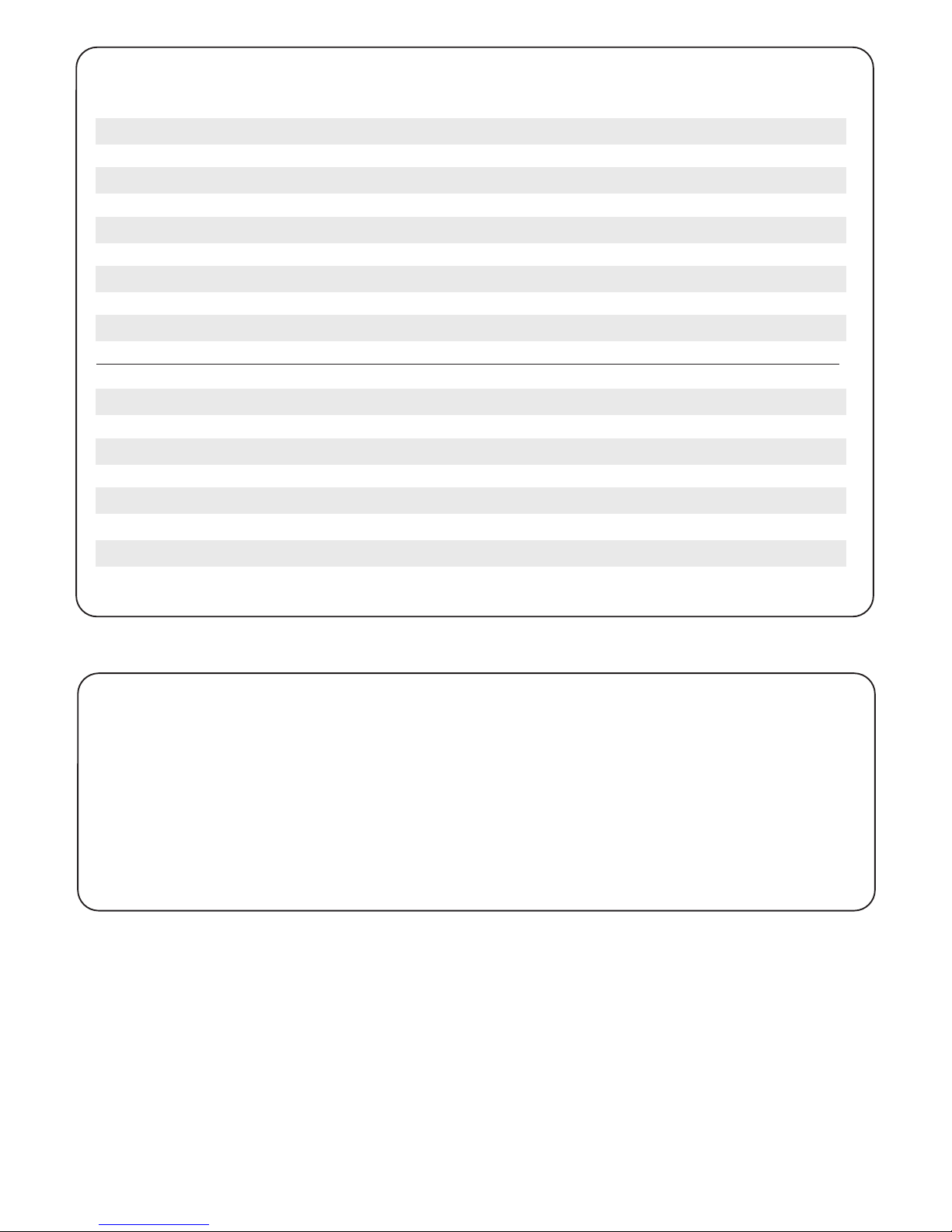
Overheated Back-up Batteries
The gate doesn’t move when pressing the
button of the transmitter
The gate only moves a little distance when
pressing the button of the transmitter.
The transmitting distance is too short
The gear motors run very slowly
The Flashing light does not work
The leaves shall be closed instead of opening
The leaves suddenly stop during moving
The leaves does not move or only move toward
one direction
The master gate closes to the end first and the
slave gate stops, the flashing light blinks fast for
five seconds.
The gear motors does not run and the relay is
noisy when operating the gate opening and
closing
Check the wiring connection of the batteries.
1. Check if LED3 or 4 is “OFF”.
2. Check if the voltage of the batteries is upon 22V.
3. Make sure all the wiring connections are firmly connected to the
terminals on the PCB.
4. Make sure the fuse is workable.
Make sure the wiring connection of the hall sensor is firm.
Make sure the connecting terminals of the
Antenna is firm.
Check the dip switch setting of the speed adjustment.
Check if the wiring connection of the flashing light is correct.
Change the polarity connection of the positive (+) with the negative (-)
of the gear motors.
1. Check if the “RESET” socket is activated.
2. Make sure the wiring connection of the gear motors is firm.
3. Make sure the hall sensor wiring connection is firm.
4. The GND terminal of the photocells on the PCB must be
short-circuited if no photocells installed.
5. Make sure the fuse is workable.
1. Check if the “RESET” socket is activated.
2. Make sure the wiring connection of the gear motors is firm.
3. Make sure the hall sensor wiring connection is firm.
4. The GND terminal of the photocells on the PCB must be
short-circuited if no photocells installed.
Cut off the AC input power and the output of the batteries. Release the
master gate and slave gate manually, then open the master to the end
and close the slave gate to the end by hand, then power the whole unit
by connecting the AC and battery terminals.
Check if the fuse is burned.
4. Trouble Shooting
190mm250mm
255.2mm
Page 20
34100-124-01-C
6. Maintenance
Conduct the following operations at least every 6 months. If in high intensity of use, shorten the period in between.
Disconnect the power supply:
(1) Clean and lubricate the screws, the pins, and the hinge with grease.
(2) Check the fastening points are properly tightened.
(3) Make the wire connection are in good condition.
Connect the power supply:
(1) Check the power adjustments.
(2) Check the function of the manual release.
(3) Check the function of photocells or other safety devise.
5.2 Technical Feature:
Model
Motor
Gear type
Nominal thrust
Maximum Gate Weight
Maximum Gate Length
Operating Temperature
Dimension
Weight
PA250
24Vdc motor
Electromechanical worm gear
2500N
250 kg per leaf
2.5 meters per leaf
-20
o
C~+50oC
256 x 187 x 267mm
6 kg
Model
Main power supply
Back-up battery
Receiver board
Installation
Operating Temperature
Dimension
PC190
230Vac/110Vac, 50Hz/60Hz
2pcs of batteries for emergency operation, 1.2A each
433.92MHz; 200 transmitters memory
Built - in PCBA
-20
o
C~+50oC
275mm x 195mm x 102mm
 Loading...