

Page 1
with a copy of the receipt with purchasing date.
MB-3690
Input Voltage
12VDC (8 ~ 16VDC operative)
Bulk / Absorption Charging
14.2V / 14.6V / 14.8V
Float Charging
Power Supply
Max. DC output current
40A
Efficiency up to
90%
Output short circuit
Yes
Dimensions (mm)
260 x 140 x 80
MB-3691
Input Voltage
24VDC (20 ~ 30VDC operative)
Bulk / Absorption Charging
14.2V / 14.6V / 14.8V
Float Charging
Power Supply
Max. DC output current
40A
Efficiency up to
90%
Output short circuit
Yes
Output terminal
2
Weight (kg)
1.6
Dimensions (mm)
260 x 140 x 80
Specifications subject to change without notice.
This device has been CE tested and
standards.
Disposal
regulations.
POWERTECH
DC-DC Isolated
4-stage
Boost Charger
MB-3690
MB-3691
INSTRUCTION MANUAL
Please read this instruction manual carefully
before operating the device.
Important Information!
Thank you for purchasing the DC-DC 4 stage boost
charger.
Please read this instruction manual carefully before
operating the device. Keep this manual in a safe place f or
future reference. This instruction manual is part of the
product. It must be handed over along with the device if it
is passed on to a third party.
WARNING! Risk of Electric Shock!
Do not open the device if it has been connected to the
battery or DC power source.
Warranty only covers the cost of parts and labor for
the repair service within the warranty period. Warranty will
not apply where the device has been misused, altered,
neglected, improperly installed, or physically damaged,
either internally or externally or damaged from improper
use or use in an unsuitable environment. W e shall not be
liable for damages, whether direct, incidental, special, or
consequential, or economic loss even though caused by
negligence, or other fault. If the device requires warranty
service, please return it to the place of purchase along
Specification
MODEL
13.2V / 13.5V / 13.8V
13.2V / 13.5V / 13.8V
Battery reverse polarity DC fuse
Input to output fully isolated. Yes
Output terminal 2
Operation temperature
Ventilation
Weight (kg) 1.6
MODEL
0°C to 40°C
Cooling Fan, thermal controlled
13.2V / 13.5V / 13.8V
13.2V / 13.5V / 13.8V
Battery reverse polarity DC fuse
Input to output fully isolated. Yes
Operation temperature
Ventilation
Cooling Fan, thermal controlled
0°C to 40°C
conforms to the applicable directives and
When the device has become unusable, dispose
of it in accordance with the applicable disposal
Page 2
Instruction and normal responses
power supply output voltage can be set by the switch No.4 and 5.
Introduction
This compact DC - DC Isolated 4 stage Boost charger uses the
insulated if it is not in use.
External switch
for remote On/Off
Apply switched
9~30VDC positive
latest switch-mode technology and is designed to meet all modern
automobile applications, particularly dual battery systems.
Galvanic isolated means you can connect to any load without
worrying about interference from the input to the output.
The 4 stage DC-DC Boost Charger is designed to charge
Lead-acid batteries in dual battery systems to their best level,
thanks to a smart 4-stage charging algorithm and voltage boosting
to deliver a full charge without the issue of voltage drops. This
improves the charge delivered to your battery, increasing battery
life and saving on premature battery failure.
Since the DC supply from a vehicle’s alternator is often unstable
leading to a shortened lifespan of electronic device, this DC-DC
isolated boost charger can be used as a constant power supply to
run accessories that require a stable and clean DC voltage.
For example: LCD TV, Digital Hi-Fi system, Wireless telephone
systems, refrigeration systems, LED lighting, games, mobile
computer and more....
The DC-DC boost charger is designed with overload and short
circuit protection. It will automatically switch off the unit and re-start
if the overload or short circuit problem is corrected. The cooling fan
is thermal controlled. It will switch on and off automatically to
control the internal temperature of the unit.
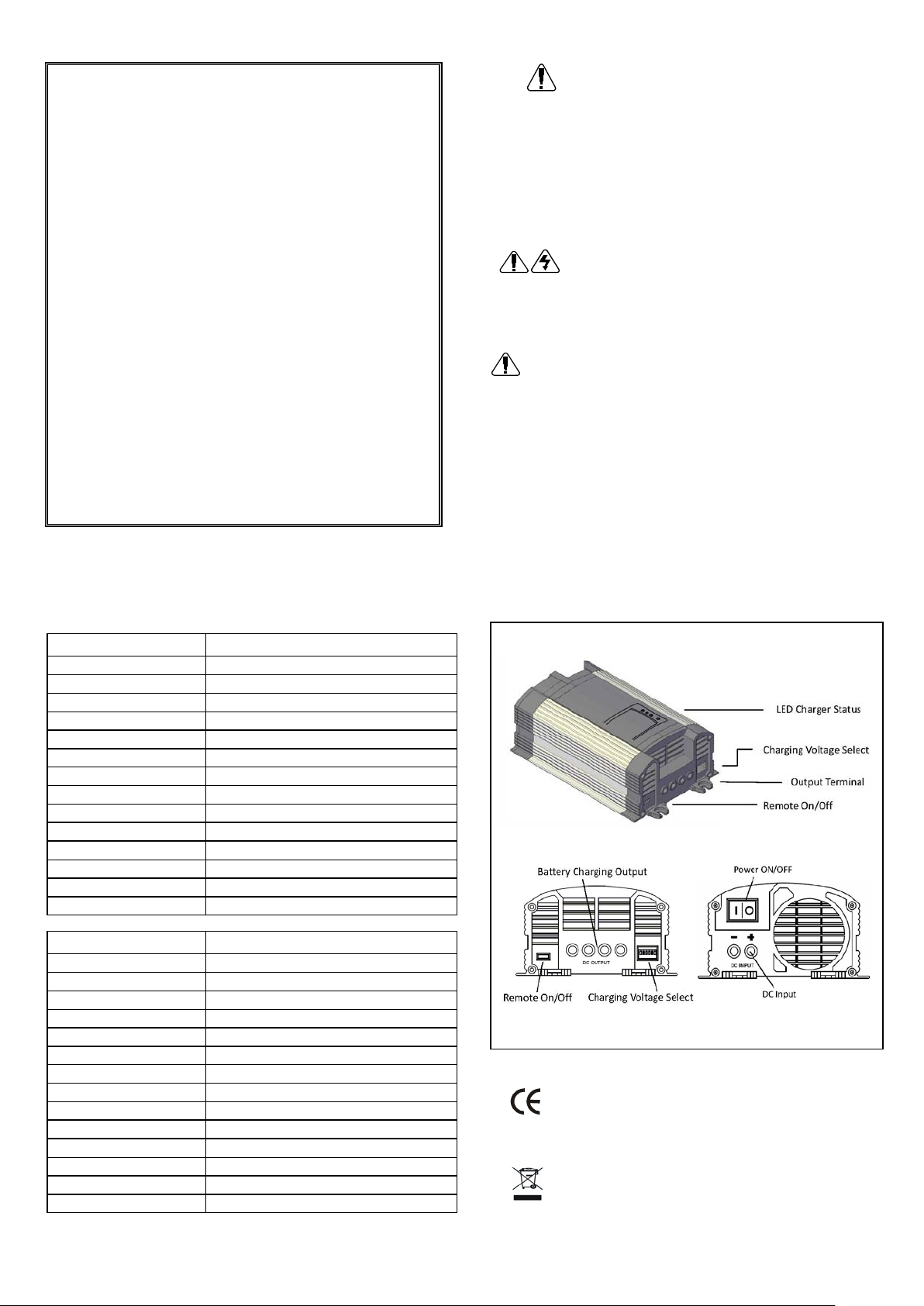
Remote on/off controls
The male terminal (6.3mm) on the front panel is used for remotely
switching on the DC-DC charger by applying 9-30VDC positive
voltage (e.g. ignition from the vehicle engine or an external switch).
Note: The working voltage is 32VDC maximum. The device power
on/off switch must be switched off if you are using this feature.
CAUTION!
Do not connect the male terminal to DC source over 32VDC or the
device will be damaged. Keep the remote ON/OFF terminal
Output Voltage Setting Table
SW No. Battery Selector Float Voltage Power Supply
1 ON OFF OFF
2 * ON OFF
3 * * ON
4 ON OFF OFF ON OFF OFF
5 OFF ON OFF OFF ON OFF
6 OFF OFF OFF OFF OFF OFF ON ON ON
12V
Output
Note: Dip-SW No. 1, 2 and 3 are switched off automatically (regardless it is on/off), when
Battery
Type
SLA / GEL
FLOODED SW 1,4 ON, SW 2,3,5,6 OFF 13.8V 14.8V
14.8 14.6 14.2 13.8 13.5 13.2 13.8 13.5 13.2
Dip-SW No. 6 is switched on.
Dip Switch Setti n g Float Volt
SW 3 ON, SW 1,2,4,5,6 OFF 13.2V 14.2V
AGM SW 2,5 ON, SW 1,3,4,6 OFF 13.5V 14.6V
Bulk /
Absorption Volt
Operation as DC booster charger
Connect the input to the DC source, such as your vehicle
alternator or cranking battery using suitable size cabling and fuse.
Adjust the charge setting dip switch to get the optimum charge to
suit your battery specification.
Connect the battery to the DC output. . Turn ON the Power switch,
the “POWER ON” LED lights up, this indicates the device is ready
for charging. The smart DC-DC boost charger will perform the
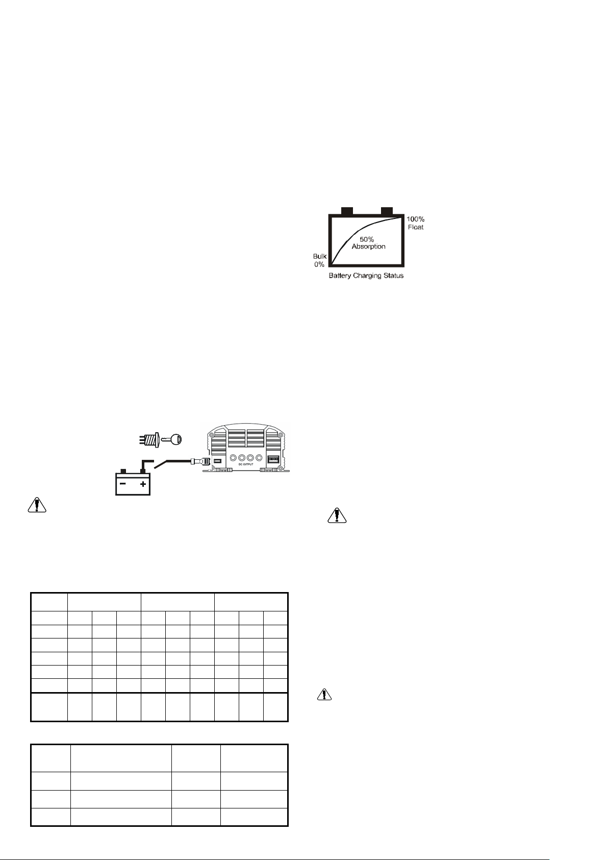
four stage charge automatically The “BULK” LED lights up. This
means the battery charger is beginning at the 1
st
stage of
charging.
st
The 1
stage is to ensure battery is
always charged at the maximum
charging condition. This is to boost
up the charging cycle and particularly
wake up a weak battery to absorb
energy.
After 10-20 mins, the charger will
switch to 2
nd
stage, the “BULK” LED
remains ON, the battery is charged at
the maximum current to the battery.
At the 3
rd
stage, the charger will switch to “ABSORPTION” mode,
the red LED goes out and the yellow LED lights up. The device is
delivering constant voltage to the battery with reduced current.
The charging voltage can be set by the switch No. 1,2 and 3.
At the 4
th
stage, the battery has been charged to about 90% of its
rated capacity. The “ABSORPTION” LED goes out and the
“FLOAT” green LED lights up. The charging current is decreased
and the charging voltage is held at a constant level. Battery is
now under “FLOAT” constant charging. The charging voltage can
be set by the switch No.4 and 5.
Operation as power supply
The device can be used as a Power Supply. Set the switch No. 6
to ON position. The device now operates as a power supply unit.
The bulk and absorption LED goes out. Switch No. 1,2 and 3 are
now disabled. The POWER ON and FLOAT LED light up. The
CAUTION!
1. Do not use the device near flammable materials or in any
location that may accumulate flammable fumes or gasses.
2. Hot surface when operating, especially at full load condition.
3. Make sure the polarity is correct
4. Do not locate the device on the top of the battery. Especially
Flooded, Wet type battery. It may generate gas vapor while
charging.
5. Do not charge non-rechargeable batteries.
6. Use the appliance only in the described manner.
7. Do not expose the device to a heat source, such as direct
sunlight or heating.
8. Store the device in a dry and cool place
Safety Operation!
A. If cables have to be fed through walls with sharp edges,
always use tubes or ducts to prevent damage.
B. Do not pull on the cable, fasten the device and cable
securely. Lay the cable so that it cannot be tripped over..
C. Use the device only in the described manner.
D. Children should be supervised to ensure that they do not
play with the device.
E. Do not allow water to drip or splash on the device.
F. Make sure the air inlets and outlets of the device are not
covered.
G. Operate the device only if you are certain that the housing
and the connection cables are undamaged.
 Loading...