

Page 1
11
10. Troubleshooting
Problem Buzzer Possible Cause Solution
No Charging
(no display)
No beep
Low input voltage
Input fuse burned
Check voltage & current
Please change by the
experienced engineer
Wrong wire connection Check connection and wires
No Charging
(with display)
No charging after
prolonged use
Long beep Input voltage deviant Check voltage & current
1 short beep
1 short beep
2 short beeps
3 short beeps
Battery is not connected
Check if poor wiring
Check if poor battery condition
or wrong voltage
Low battery voltage
High battery voltage Check if wrong voltage
Over temperature
Improve ventilation
Reduce ambient temperature
DISTRIBUTED BY:
TechBrands by Electus Distribution Pty. Ltd.
320 Victoria Rd, Rydalmere
NSW 2116 Australia
Ph: 1300 738 555
Int’l: +61 2 8832 3200
Fax: 1300 738 500
www.techbrands.com
Made in Taiwan
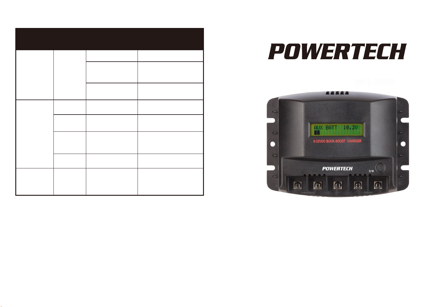
12V DC-DC Battery Charger
User Manual
MB-3684 (20A)
MB-3689 (30A)
Page 2
12V DC-DC Battery Charger MB-3684(20A),MB-3689(30A)
Thank you for purchasing this product.
Properly used, this product will provide years of reliable
service. Please read this manual carefully, understand
and comply with all instructions before use.
Table of Contents
1. Overview.......................................................Page.2
3. Recommendation of Battery Capacity..........Page. 4
4. Safety Instructions and Warnings.................Page. 5
5. Maintenance.................................................Page. 6
6. Mounting The Charger..................................Page. 7
7. Wire Connection...........................................Page. 7~8
8. Dis
play during operation...............................Page. 8-10
9. The Error Code.............................................Page. 10
10. Troubleshooting .........................................Page. 11
1
2. Specification..................................................Page.3
A U X B A T T 1 2 . 5 V
V I : E R R OR
The Display Code
De scr iption How buzzer operate
Input voltage error Continuous Alarm
B A T T E R Y
W
R ONG
Low Battery Voltage
a short beep
B A T T E R Y
W
R ONG
High Battery Voltage
tw o short be eps
B A T T E R YON
Battery disconnection
a sh ort b eep
MP .T E RORRE
three short bee ps
* Battery Voltage Display Function
4-2-1. It gets into Sleep Mode when the Ignition Switch off
but battery is connected
4-2-2. Display shows Battery
Voltage if to press the Function
Switch in Sleep Mode.
4-2-3. It moves back to Sleep Mode again after 10 seconds.
4-2-4. Press the Function Switch in Sleep Mode and battery
voltage is less than 10.5V, buzzer sounds for 10
seconds, then moves back to Sleep Mode again
9. The Error Code
( See table description below for more information)
10
Temp deviant
Page 3

9
3-1. Press the Function Switch for 3 seconds in charging mode,
buzzer sounds and gets into
stand-by mode.
3-2. Press 2 times consecutively the Function Switch in
stand-by status to change the charging mode.
R E AD Y T O
C H A R G
L E A D AC I D
M
ODE
E
Charging Lead Acid Battery (Default)
Charging Voltage: DC14.4V
Floating Charging Voltage: DC13.3V
Charging AGM Batter
y
Charging Voltage: DC14.7
V
Floating Charging Voltage: DC13.6V
Charging GEL Battery
Charging Voltage: DC14.1V
Floating Charging Voltage: DC13.1V
3-3. Press the Function Switch for 3 seconds in stand-by mode,
buzzer sounds and move back to Charging mode, the setting
will be recorded as default for next charging.
Step 4:
* Battery Charging Finish
4-1-1. While display shows Vb (Battery Voltage) consecutively
same as voltage as following, it means battery charger is in
floating mode and battery is fully
charged.
LEAD ACID MODE: Vb:13.3V
AGM MODE: Vb:13.6V
GEL MODE: Vb:13.1V
LEG
M
ODE
V b : 1 3 . 1 V I : 0 1 . 0 A
A G
M
ODE
V b : 1 3 . 6 V I : 0 1 . 0 A
M
L E A D AC I DMODE
V b : 1 3 . 3 V I : 0 1 . 0 A
R E AD Y T O
C H A R G
L E A D AC I D
M
ODE
E
R E AD Y T O
C H A R G
G E L
M
O
D E
E
R E AD Y T O
C H A R G
A GM
M
OD E
E
2
1.Overview
FAN
Charger Status Display
Mounting
Holes
Function Switch
Power Input Auxiliary Battery
Terminal
Charger ON/OFF Control Pin(ACC)
Page 4

3
2. Specification
Power Input
DC 9~32V
Current Range
DC 40A
DC 30A
Efficiency(%)
>92%
DC Output
Battery Charging
Type
AGM
Lead acid
GEL
Selectable
Charging Current Max.
30A
20A
Charging Voltage
DC14.4V DC14.7V DC14.1V
Floating Charging Voltage
DC13.3V DC13.6V DC13.1V
Charging
Mode
Step 1
Constant-Current
Step 2
Constant-Voltage
Step 3
Floating
Protection
DC Input High Voltage
>32V
DC Input Low Voltage
<9V
DC Input Polarity Protection YES(By Fuse)
DC Input Fuses
20A * 2pcs
15A * 2pcs
DC Output Short Protection
YES
Overtemp Protection
YES
Display
LCD
Function Selection
By Switch
Cooling
Temperature Controlled Fan
Wire Connection
Terminal With M4 Screw
Dimension
180(W)*134(H)*60(D)mm
Weight
385g
Voltage Range
MB-3684 MB-3689
Mode No.
–20°C ~ 65°C / –4°F~ 149°F
Operating Temperature Range
–20°C~ 40°C / –4°F~ 104°F
Storage Temperature Range
8. Display During Operation
Step 1:
When the charger power up, it shows
:
Step 2
:
Understanding the display information:
When detect Input and Battery Voltage,
it shows:
If input voltage is out of range, it shows:
If Aux. battery voltage is out of range,
it shows:
Please refer to Step 3 if Input Voltage &
Battery Voltage operate normally
Step 3:
* When Battery Charging Start, display is
showing as below:
"LEAD ACID MODE" : Charging Lead Acid Battery
"Vb: 14.4V" : Battery Voltage
"I:20.0A", "I:30.0A" : Battery Charging Current
* Battery Charging Stop or Change Charging Mode:
B A T T ER Y T E S T I N G
V I : E R ROR
B A T TER Y
W
R ON G
L E A D A C I DMODE
V b : 1 4 . 4 V I : 3 0 . 0 A
L E A D A C I DMODE
V b : 1 4 . 4 V I : 2 0 . 0 A
P OW E R T C HE
M B - 63 8 9 3 0 A
P OW E R T C HE
M B - 63 8 4 2 0 A
8
Operation:
1.Wire ACC and Vehicle Ignition Switch
2.Use Start / Vehicle battery to charge the Auxiliary Battery
via Vehicle Ignition Switch.
The battery charger is powered when Ignition Switch turn to
“ON” and start to charge battery.
The battery charger stop charging when Ignition Switch turn to
“LOCK”, and insulate the Start/Vehicle battery for power saving.
Caution:Please pay attention to polarity while connect wire.
Wrong connection will cause the product damage.
Page 5

7
6. Mounting The Charger
6-1.For installing in a car or boat environment, the charger
should be mounted vertically. This provides the best
thermal performance and drip protection.
6-2.Use the base of the charger as a mounting template to
mark the positions
of the fixing
screws.
Unit: mm
7. Wire Connection
Use Car Ignition
Switch To Start
The Charger
4
3. Recommendation of Battery Capacity
Attention :
1.Auxiliary battery capacity : it recommends 4 times of max.
charging current. According to battery manufacturer, it can
maximize the battery life span if to charge battery with
current less than 0.25C.
e.g. 1C = the battery capacity
1C = DC12V / 80AH, 0.25C = 20A
2.Please charge the battery at least once every 3 months
3.Battery voltage checking:
Remark: Above DC13V is just a reference, please check
the specifications provided by the battery supplier for
exact data.
no exceed charging current 0.25C to
maximize the battery life
Model No.
MB-3684
MB-3689
Charging Current
20A
30A
Auxiliary Battery
Capacity
DC12V / 80AH (Min.)
DC12V / 120AH (Min.)
Battery Voltage
Battery Status
>DC13V
<DC12.4V
Battery is full
need to recharge battery
Page 6

4.Safety Instructions and Warnings
1.Dry- Do not allow water to drip or splash on the charger
2.Cool- Ambient air temperature should be between 0 and 40°C,
the cooler the better.
3.Safe- Do not install in a battery compartment or other areas
engine compartments.
4.Ventilated- Allow at least one inch of clearance around the
Ensure the ventilation openings on the rear and front of the unit
are not obstructed.
5.Dust- Do not install the charger in a dusty environments where
These dust can be pulled into the unit when the cooling fan is
operating.
6.Close to batteries- Avoid excessive cable lengths but do not
install the charger in the same compartment as batteries.
Your cables should be as short as possible enough to handle the
required current in accordance with the electrical codes or
regulation application.
The Charger should be installed in a location that meets
the following requirements.
5
6
gases produced by the battery.
These gases are very corrosive and prolonged exposure also will
damage the charger.
Also do not mount the charger where it will be exposed to the
WARNING!
Shock Hazard. Before proceeding further, carefully check
that the charger is NOT connected to any batteries, and
that all wiring is disconnected from any electrical sources.
Make sure all the wire connection are tight.
Loose connections could result overheat in a potential
hazard.
Do not open or disassemble the charger.
Attempting to service the unit yourself may
5. Maintenance
Very little maintenance is required to keep your charger
operating properly.
You should clean the exterior of the unit periodically with a
damp cloth to prevent accumulation of dust and dirt.
At the same time, tighten the screws on the power input ,
battery and ACC terminals.
 Loading...