

PowerTech CD4045HF120, CD4045DF120, CD4045TF120, CD4045TF220, CD6068TF120 Operator's Manual
...Page 1

PowerTech
4.5 L and 6.8 L
Non-Certified and
Tier 1 Certified
OEM Diesel Engines
OPERATOR’S MANUAL
PowerTech 4.5 L and 6.8 L
Non-Certified and Tier 1 Certified
OEM Diesel Engines
OMRG25204 Issue 02Nov06 (ENGLISH)
CALIFORNIA
Proposition 65 Warning
Diesel engine exhaust and some of its constituents are
known to the State of California to cause cancer, birth
defects, and other reproductive harm.
If this product contains a gasoline engine:
WARNING
The engine exhaust from this product contains chemicals
known to the State of California to cause cancer, birth
defects or other reproductive harm.
The State of California requires the above two warnings.
John Deere Power Systems
LITHO IN U.S.A.
Page 2

Foreword
Introduction
This manual contains information to operate and
service the following 4.5 L & 6.8 L non-certified and
Tier 11emission certified OEM engines built at
Dubuque Iowa (T0), Saran France (CD) and Torreon
Mexico (PE) from 1996 on. These engines have
mechanically-controlled fuel systems.
SARAN BUILT NON-CERTIFIED ENGINES
• CD4045DF120
• CD4045TF120
• CD4045TF220
• CD4045HF120
• CD6068TF120
• CD6068TF220
• CD6068HF120
TORREON BUILT NON-CERTIFIED ENGINES
• PE4045TF120
• PE4045TF220
• PE4045HF120
• PE6068TF120
• PE6068TF220
• PE6068HF120
DUBUQUE BUILT NON-CERTIFIED ENGINES
• T04045DF120
• T04045TF120
• T04045TF220
• T04045HF120
SARAN BUILT TIER 1 CERTIFIED ENGINES
• CD4045DF150
• CD4045DF151
• CD4045DF152
• CD4045DF153
• CD4045DF154
• CD4045DF157
• CD4045DF158
• CD4045TF150
• CD4045TF152
• CD4045TF154
• CD4045TF155
• CD4045TF157
• CD4045TF158
• CD4045TF161
• CD4045TF162
• CD4045TF250
• CD4045TF251
• CD4045TF252
• CD4045TF253
• CD4045TF257
• CD4045TF258
• CD4045HF150
• CD4045HF152
• CD4045HF157
• CD4045HF158
• CD4045HF252
• CD6068DF150
• CD6068TF150
• CD6068TF151
• CD6068TF152
• CD6068TF157
• CD6068TF158
• CD6068TF159
• CD6068TF250
• CD6068TF251
• CD6068TF257
• CD6068TF258
• CD6068HF150
• CD6068HF157
• CD6068HF158
• CD6068HF250
• CD6068HF252
• CD6068HF254
• CD6068HF258
TORREON BUILT TIER 1 CERTIFIED ENGINES
• PE4045DF150
• PE4045TF150
1
Emission certified for United States as EPA Tier 1 and European
Union as Stage 1.
OURGP11,0000004 –19–27OCT06–1/2
110306
PN=2
Page 3

Introduction
• PE4045TF151
• PE4045HF150
• PE4045HF252
• PE6068DF150
• PE6068TF150
• PE6068TF151
• PE6068TF250
• PE6068HF150
• PE6068HF250
DUBUQUE BUILT TIER 1 CERTIFIED ENGINES
• T04045DF150
• T04045DF151
• T04045DF152
• T04045DF153
• T04045TF150
• T04045TF151
• T04045TF152
• T04045TF250
• T04045TF251
• T04045HF120
• T04045HF150
• T06068DF150
• T06068TF150
• T06068TF151
• T06068TF250
• T06068HF150
• T06068HF250
NOTE: Before 2005, all Non-certified and Tier 1
Certified Saran built engines used the following
serial number sequences:
•
(CDxxxxD500000) - (CDxxxxD799999)
•
(CDxxxxT500000) - (CDxxxxT799999)
•
(CDxxxxH500000) - (CDxxxxH799999)
Since 2005, non-certified engines have the
seventh digit of the serial number as “B” while
Tier 1 certified engines have the seventh digit
as “C”.
READ THIS MANUAL carefully to learn how to operate
and service your engine correctly. Failure to do so
could result in personal injury or equipment damage.
THIS MANUAL SHOULD BE CONSIDERED a
permanent part of your engine and should remain with
the engine when you sell it.
MEASUREMENTS IN THIS MANUAL are given in both
metric and customary U.S. unit equivalents. Use only
correct replacement parts and fasteners. Metric and
inch fasteners may require a specific metric or inch
wrench.
RIGHT-HAND AND LEFT-HAND sides are determined
by standing at the drive or flywheel end (rear) of the
engine and facing toward the front of the engine.
WRITE ENGINE SERIAL NUMBERS and option codes
in the spaces indicated in the Record Keeping Section.
Accurately record all the numbers. Your dealer also
needs these numbers when you order parts. File the
identification numbers in a secure place off the engine.
SETTING FUEL DELIVERY beyond published factory
specifications or otherwise overpowering will result in
loss of warranty protection for this engine.
CERTAIN ENGINE ACCESSORIES such as radiator,
air cleaner, and instruments are optional equipment on
John Deere OEM Engines. These accessories may be
provided by the equipment manufacturer instead of
John Deere. This operator’s manual applies only to the
engine and those options available through the John
Deere distribution network.
NOTE: This operators manual covers only engines
provided to OEM (Outside Equipment
Manufacturers). For engines in Deere
machines, refer to the machine operators
manual.
OURGP11,0000004 –19–27OCT06–2/2
110306
PN=3
Page 4

Engine Owner
Introduction
John Deere Engine Owner:
Don’t wait until you need warranty or other service to
meet your local John Deere Engine Distributor or
Service Dealer. To register your engine for warranty
via the Internet, use the following URL:
http://www.johndeere.com/enginewarranty
Learn who your dealer is and where he is. At your first
convenience, go meet him. He’ll want to get to know
you and to learn what your needs might be.
Aux Utilisateurs De Moteurs John Deere:
N’attendez pas d’eˆtre oblige´d’avoir recours a`votre
concessionnaire John Deere ou au point de service le
plus proche pour vous adresser a`lui. Pour enregistrer
votre moteur pour la garantie via Internet, utilisez
l’adresse suivante:
http://www.johndeere.com/enginewarranty
Renseignez-vous de`s que possible pour l’identifier et
le localiser. A la premie`re occasion, prenez contact
avec lui et faites-vous connaıˆtre. Il sera lui aussi
heureux de faire votre connaissance et de vous
proposer ses services le moment venu.
An Den Besitzer Des John Deere Motors:
Warten Sie nicht auf einen evt. Reparaturfall, um den
na¨chstgelegenen John Deere Ha¨ndler kennen zu
lernen. Zur Registrierung Ihres Motors fu¨r die Garantie
dient folgende Internet-Adresse:
http://www.johndeere.com/enginewarranty
distributore dei motori John Deere o del
concessionario che fornisce l’assistenza tecnica. Per
registrare via Internet la garanzia del suo motore, si
collegi al seguente sito URL:
http://www.johndeere.com/enginewarranty
Lo identifichi e si informi sulla sua ubicazione. Alla
prima occasione utile lo contatti. Egli desidera fare la
sua conoscenza e capire quali potrebbero essere le
sue necessita`.
Propietario De Equipo John Deere:
No espere hasta necesitar servicio de garantı´aode
otro tipo para conocer a su Distribuidor de Motores
John Deere o al Concesionario de Servicio. Registre
su motor para la garantı´a en la siguiente direccio´nde
internet: http://www.johndeere.com/enginewarranty
Ente´rese de quie´nes,ydo´nde esta´situado. Cuando
tenga un momento, vaya a visitarlo. A e´l le gustara
´
conocerlo, y saber cua´les podrı´an ser sus
necesidades.
Till a¨gare av John Deere motorer:
Ta reda pa˚vem din a˚terfo¨rsa¨ljare a¨r och beso¨k honom
sa˚snart tillfa¨lle ges. Va¨nta inte tills det a¨r dags fo¨r
service eller eventuellt garantiarbete. Din motor
garantiregistrerar Du via Internet pa
˚
http://www.johndeere.com/enginewarranty
Din a˚terfo¨rsa¨ljare vill mycket ga¨rna tra¨ffa dig fo¨r att la¨ra
ka¨nna dina behov och hur ba¨st han kan hja¨lpa dig.
Machen Sie sich bei ihm bekannt und nutzen Sie sein
“Service Angebot”.
Proprietario del motore John Deere:
Non aspetti fino al momento di far valere la garanzia o
di chiedere assistenza per fare la conoscenza del
OURGP11,0000251 –19–11OCT06–1/1
110306
PN=4
Page 5
Introduction
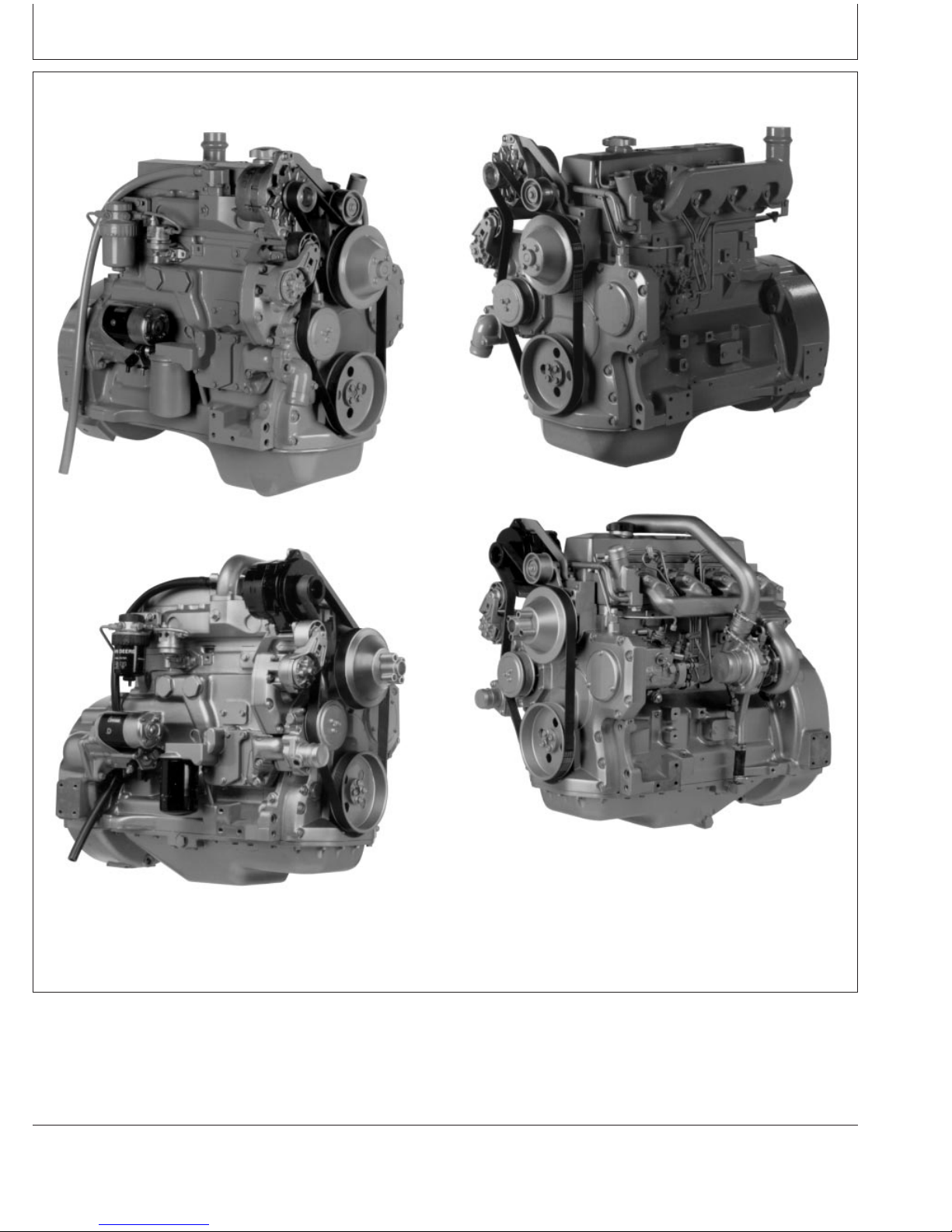
POWERTECH4.5 L Engines With Mechanical Controls (Tier 1 Emission Certified)
4045D Engine
4045T Engine
4045D Engine
RG7998 –UN–19JUN00
RG7999 –UN–19JUN00
RG7997 –UN–19JUN00
4045T Engine
RG7996 –UN–19JUN00
P
OWERTECH
is a trademark of Deere & Company
RG,RG34710,5501 –19–04JAN02–1/1
110306
PN=5
Page 6
Introduction
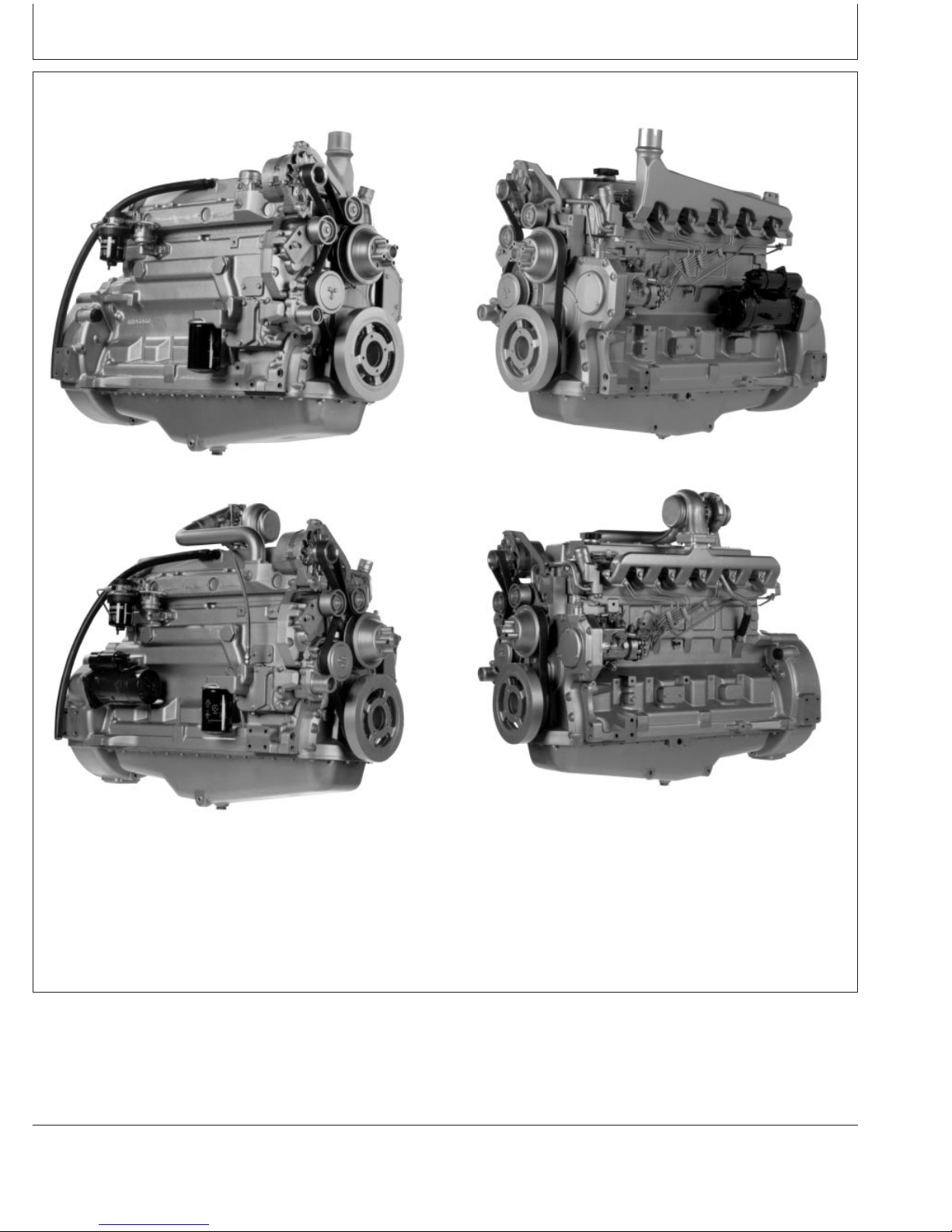
POWERTECH6.8 L Engines With Mechanical Controls (Tier 1 Emission Certified)
6068D Engine
6068T Engine
RG8003 –UN–19JUN00
RG8001 –UN–19JUN00
6068D Engine
RG8002 –UN–19JUN00
RG8000 –UN–19JUN00
6068T Engine
P
OWERTECH
is a trademark of Deere & Company
RG,RG34710,5503 –19–04JAN02–1/1
110306
PN=6
Page 7

Contents
Page Page
Record Keeping
PowerTech Medallion.....................01-1
Engine Serial Number Plate ................01-1
Record Engine Serial Number ..............01-2
Engine Option Codes .....................01-3
Record Fuel Injection Pump Model Number ....01-5
Safety ................................05-1
Fuels, Lubricants, and Coolant
Diesel Fuel.............................10-1
Lubricity of Diesel Fuel....................10-1
Handling and Storing Diesel Fuel ............10-2
Testing Diesel Fuel.......................10-2
Bio-Diesel Fuel..........................10-3
Aviation (Jet) Fuels.......................10-4
Burner Fuels............................10-4
Minimizing the Effect of Cold Weather on
Diesel Engines ........................10-5
Diesel Engine Break-In Oil .................10-6
Diesel Engine Oil ........................10-7
Extended Diesel Engine Oil Service Intervals. . . 10-8
Mixing of Lubricants ......................10-8
OILSCANand COOLSCAN ..............10-9
Alternative and Synthetic Lubricants..........10-9
Lubricant Storage.......................10-10
Oil Filters .............................10-10
Grease...............................10-11
Diesel Engine Coolant ...................10-12
Drain Intervals for Diesel Engine Coolant ....10-13
Additional Information About Diesel
Engine Coolants and Supplemental Coolant
Additives............................10-14
Supplemental Coolant Additives............10-15
Additional Information About Diesel
Engine Coolants and Supplemental Coolant
Additives............................10-16
Testing Diesel Engine Coolant .............10-17
Operating in Warm Temperature Climates ....10-18
Disposing of Coolant ....................10-18
Engine Operating Guidelines
Instrument (Gauge) Panels.................15-1
Instrument (Gauge) Panel (North America).....15-2
VDO Instrument (Gauge) Panel (Except
North America) ........................15-4
Engine Break-In Service...................15-6
Auxiliary Gear Drive Limitations .............15-9
Generator Set (Standby) Applications.........15-9
Starting the Engine......................15-10
Warming Engine........................15-12
Normal Engine Operation.................15-13
Cold Weather Operation..................15-14
Changing Engine Speed..................15-15
Avoid Excessive Engine Idling .............15-15
Stopping the Engine.....................15-16
Using a Booster Battery or Charger .........15-17
Lubrication and Maintenance
Observe Service Intervals..................20-1
Use Correct Fuels, Lubricants, and Coolant ....20-1
Lubrication and Maintenance Service
Interval Chart—Standard Industrial Engines . . 20-2
Lubrication and Maintenance Service
Interval Chart—Generator (Standby)
Applications ..........................20-4
Lubrication & Maintenance/Daily
Daily Prestarting Checks ..................25-1
Lubrication & Maintenance/250 Hour/6 Month
Servicing Fire Extinguisher.................30-1
Changing Engine Oil and Replacing Filter .....30-2
Checking Engine Mounts ..................30-4
Servicing Battery ........................30-5
Manual Belt Tensioner Adjustment...........30-7
Manual Belt Tensioner Adjustment Using
Belt Tension Tool (Alternate Method
For Engines Without Auxiliary Drive)........30-8
Lubrication & Maintenance/500 Hour/12 Month
Cleaning Crankcase Vent Tube .............35-1
Checking Air Intake System ................35-2
Replacing Fuel Filter Element (Single Filter)....35-3
Continued on next page
All information, illustrations and specifications in this manual are based on
the latest information available at the time of publication. The right is
reserved to make changes at any time without notice.
COPYRIGHT2006
DEERE & COMPANY
Moline, Illinois
A John Deere ILLUSTRUCTIONManual
i
All rights reserved
Previous Editions
Copyright1996, 2000, 2002, 2004
110306
PN=1
Page 8

Contents
Page Page
Replacing Fuel Filter Elements (Dual Filters) . . . 35-5 Specifications
General OEM Engine Specifications—4.5 LChecking Belt Tensioner Spring Tension
and Belt Wear (Automatic Tensioner) .......35-6 Engines..............................60-1
General OEM Engine Specifications—6.8 LChecking Engine Speeds ..................35-9
Checking Engine Electrical Ground Engines..............................60-2
Engine Power Ratings And Fuel InjectionConnections ..........................35-9
Checking Cooling System.................35-10 Pump Specifications ....................60-3
Engine Crankcase Oil Fill Quantities ........60-11Replenishing Supplemental Coolant
Additives (SCAs) Between Coolant Unified Inch Bolt and Screw Torque Values . . . 60-15
Metric Bolt and Screw Torque Values........60-16Changes ............................35-11
Testing Diesel Engine Coolant .............35-12
Pressure Testing Cooling System...........35-13 Lubrication and Maintenance Records
Using Lubrication and Maintenance Records . . . 65-1
Lubrication & Maint./2000 Hour/24 Month
Adjusting Variable Speed (Droop) on
Generator Set Engines ..................40-1
Checking Crankshaft Vibration Damper
(6-Cylinder Engine Only).................40-3
Daily (Prestarting) Service .................65-1
250 Hour/6 Month Service .................65-2
500 Hour/12 Month Service ................65-3
2000 Hour/24 Month Service ...............65-4
Service as Required......................65-5
Flushing and Refilling Cooling System ........40-4
Testing Thermostats Opening Temperature ....40-7
Check and Adjust Valve Clearance .........40-10
Emission System Warranty
U.S. EPA Emissions Control Warranty
Statement ............................70-1
Service as Required
Emissions Control System Certification Label. . . 70-1
Additional Service Information ..............45-1
Do Not Modify Fuel System ................45-1
Adding Coolant..........................45-2
Replacing Single Stage Air Cleaner ..........45-3
Replacing Axial Seal Air Cleaner Filter
Element .............................45-4
Replacing Radial Seal Air Cleaner Filter
Element .............................45-6
Replacing Fan and Alternator Belts ..........45-8
Checking Fuses In Instrument Panels ........45-9
Checking Air Compressors................45-10
Bleeding the Fuel System.................45-11
Troubleshooting
General Troubleshooting Information .........50-1
Engine Wiring Diagram Legend
(Standard Instrument Panel For North
America) .............................50-3
Wiring Diagram (Standard Instrument
Panel For North America) ................50-4
Engine Wiring Diagram—VDO
Instrument Panel (Except North America) ....50-5
Engine Wiring Diagram Legend—VDO
Instrument Panel (Except North America) ....50-6
Engine Troubleshooting ...................50-7
Storage
Engine Storage Guidelines.................55-1
Preparing Engine for Long Term Storage......55-2
Removing Engine from Long Term Storage ....55-3
ii
110306
PN=2
Page 9

POWERTECHMedallion
Record Keeping
A medallion is located on the rocker arm cover which
identifies each engine as a John Deere P
OWERTECH
engine.
RG11608 –UN–17OCT01RG11609 –UN–17OCT01
P
OWERTECH
is a trademark of Deere & Company.
Engine Serial Number Plate
Each engine has a 13-digit John Deere engine serial
number. The first two digits identify the factory that
produced the engine:
• “T0” indicates the engine was built in Dubuque, Iowa
• “CD” indicates the engine was built in Saran, France
• “PE” indicates the engine was built in Torreon, Mexico
• “J0” indicates the engine was built in Rosario, Argentina
Your engine’s serial number plate (A) is located on the
right-hand side of cylinder block behind the fuel filter.
01-1
RG,RG34710,5505 –19–04JAN02–1/1
RG8007 –UN–15JAN99
13-Digit Engine Serial Number Plate
RG,RG34710,5506 –19–04JAN02–1/1
110306
PN=9
Page 10

Record Keeping
Record Engine Serial Number
Record all of the numbers and letters found on your
engine serial number plate in the spaces provided below.
This information is very important for repair parts or
warranty information.
Engine Serial Number (B)
Engine Model Number (C)
Coefficient of Absorption Value (D)
(Saran Engines Only)
Dubuque Engine Serial Number Plate
RG7936 –UN–13NOV97
Saran Engine Serial Number Plate
Torreon Engine Serial Number Plate
RG,RG34710,5507 –19–04JAN02–1/1
RG7935 –UN–13NOV97
RG9062 –UN–16MAR98
01-2
110306
PN=10
Page 11

Engine Option Codes
Record Keeping
Engine Option Codes
A—Engine Base Code
In addition to the serial number plate, OEM engines
have an engine option code label affixed to the rocker
arm cover. These codes indicate which of the engine
options were installed on your engine at the factory.
When in need of parts or service, furnish your
authorized servicing dealer or engine distributor with
these numbers.
The engine option code label includes an engine base
code (A). This base code must also be recorded along
with the option codes.
The first two digits of each code identify a specific
group, such as alternators. The last two digits of each
code identify one specific option provided on your
engine, such as a 12-volt, 55-amp alternator.
NOTE: These option codes are based on the latest
information available at the time of publication.
The right is reserved to make changes at any
time without notice.
RG10603A –UN–15JUN00
If an engine is ordered without a particular component,
the last two digits of that functional group option code
will be 99, 00, or XX. The list on the next page shows
only the first two digits of the code numbers. For future
reference such as ordering repair parts, it is important
to have these code numbers available. To ensure this
availability, enter the third and fourth digits shown on
your engine option code label in the spaces provided
on the following page.
Continued on next page
01-3
OURGP11,0000005 –19–24JUN04–1/2
110306
PN=11
Page 12

Record Keeping
NOTE: Your engine option code label may not contain
all option codes if an option has been added
after the engine left the producing factory.
An additional option code label may also be
delivered with the engine. Place this sticker or
tag, for reference, either on this page or in the
engine owner’s warranty booklet under
If option code label is lost or destroyed,
OPTION CODES title.
consult your servicing dealer or engine
distributor selling the engine for a replacement.
Option Codes Description Option Codes Description
11 Rocker Arm Cover 45 Balancer Shafts
12 Oil Fill Inlet 46 Cylinder Block With Liners and Camshaft
13 Crankshaft Pulley 47 Crankshaft and Bearings
14 Flywheel Housing 48 Connecting Rods and Pistons
15 Flywheel 49 Valve Actuating Mechanism
16 Fuel Injection Pump 50 Oil Pump
17 Air Inlet 51 Cylinder Head With Valves
18 Air Cleaner 52 Auxiliary Gear Drive
19 Oil Pan 55 Shipping Stand
20 Coolant Pump 56 Paint Option
21 Thermostat Cover 57 Coolant Pump Inlet
22 Thermostat 59 Oil Cooler
23 Fan Drive 60 Add-on Auxiliary Drive Pulley
24 Fan Belt 62 Alternator Mounting Bracket
25 Fan 64 Exhaust Elbow
26 Engine Coolant Heater 65 Turbocharger
27 Radiator 66 Coolant Temperature Switch
28 Exhaust Manifold 67 Electronic Tachometer Sensor
29 Crankcase Ventilator System 68 Crankshaft Rear Damper
30 Starter Motor 69 Engine Serial Number Plate
31 Alternator 74 Air Conditioning (Freon) Compressor
32 Instrument Panel 75 Air Restriction Indicator
33 Tachometer 76 Oil Pressure Switch
35 Fuel Filters 78 Air Compressor
36 Front Plate 81 Water Separator
37 Fuel Transfer Pump 86 Fan Pulley
39 Thermostat Housing 87 Belt Tensioner
40 Oil Dipstick 88 Oil Filter
41 Belt-Driven Front Auxiliary Drive 95 Special Equipment (Factory Installed)
43 Starting Aid 97 Special Equipment (Field Installed)
44 Timing Gear Cover With Gears 98 Shipping
99 Service Only Items
01-4
Engine Base Code (See “A” on previous page.)
OURGP11,0000005 –19–24JUN04–2/2
110306
PN=12
Page 13

Record Keeping
Record Fuel Injection Pump Model Number
Record the fuel injection pump model and serial
information found on the serial number plate (A).
Model No. RPM
Manufacturer’s No.
Serial No.
A—Serial Number Plate
Record Injection Pump Serial Number
RG8008A –UN–13JUN00
RG,RG34710,5511 –19–20MAY96–1/1
01-5
110306
PN=13
Page 14
Safety
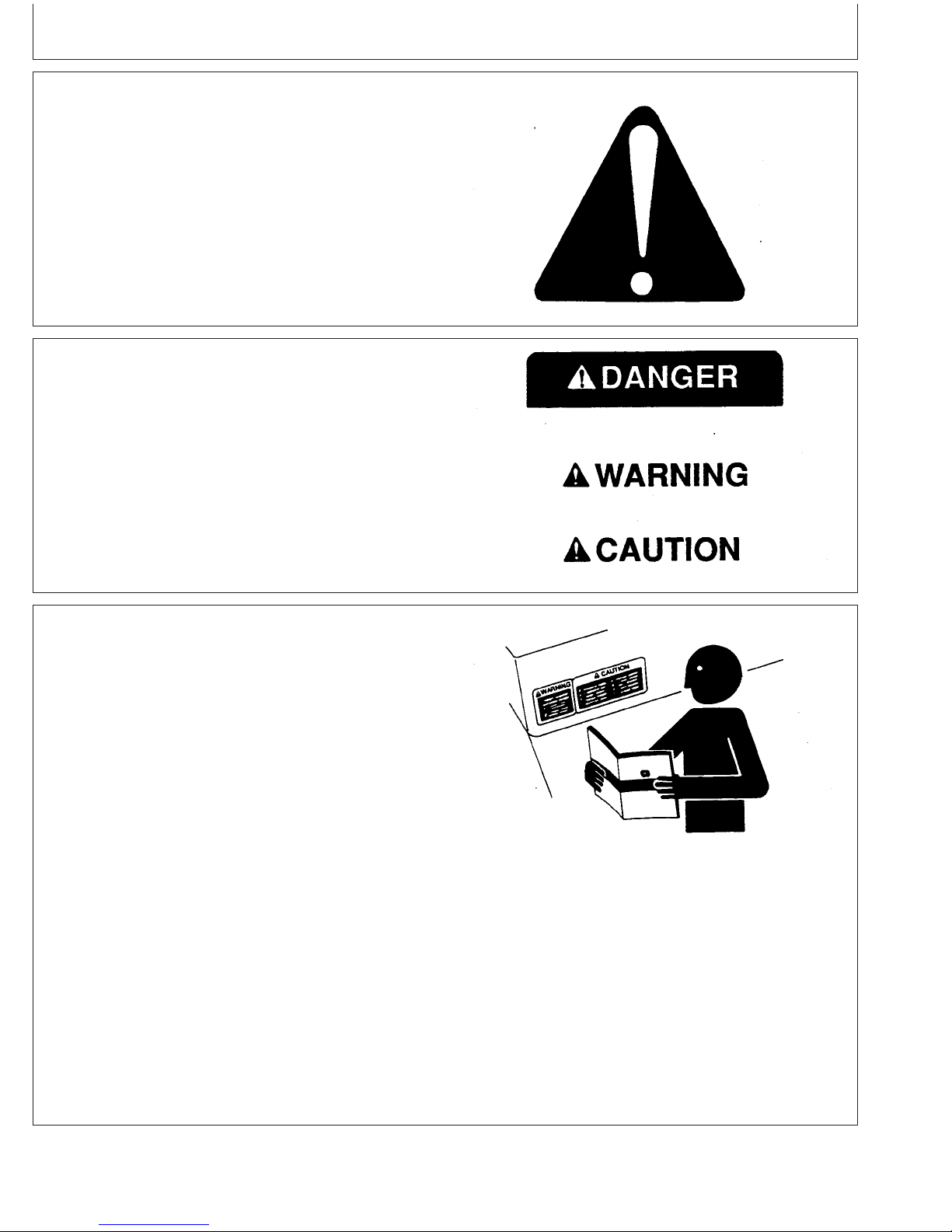
Recognize Safety Information
This is a safety-alert symbol. When you see this symbol
on your machine or in this manual, be alert to the
potential for personal injury.
Follow recommended precautions and safe operating
practices.
Understand Signal Words
A signal word—DANGER, WARNING, or CAUTION—is
used with the safety-alert symbol. DANGER identifies the
most serious hazards.
DANGER or WARNING safety signs are located near
specific hazards. General precautions are listed on
CAUTION safety signs. CAUTION also calls attention to
safety messages in this manual.
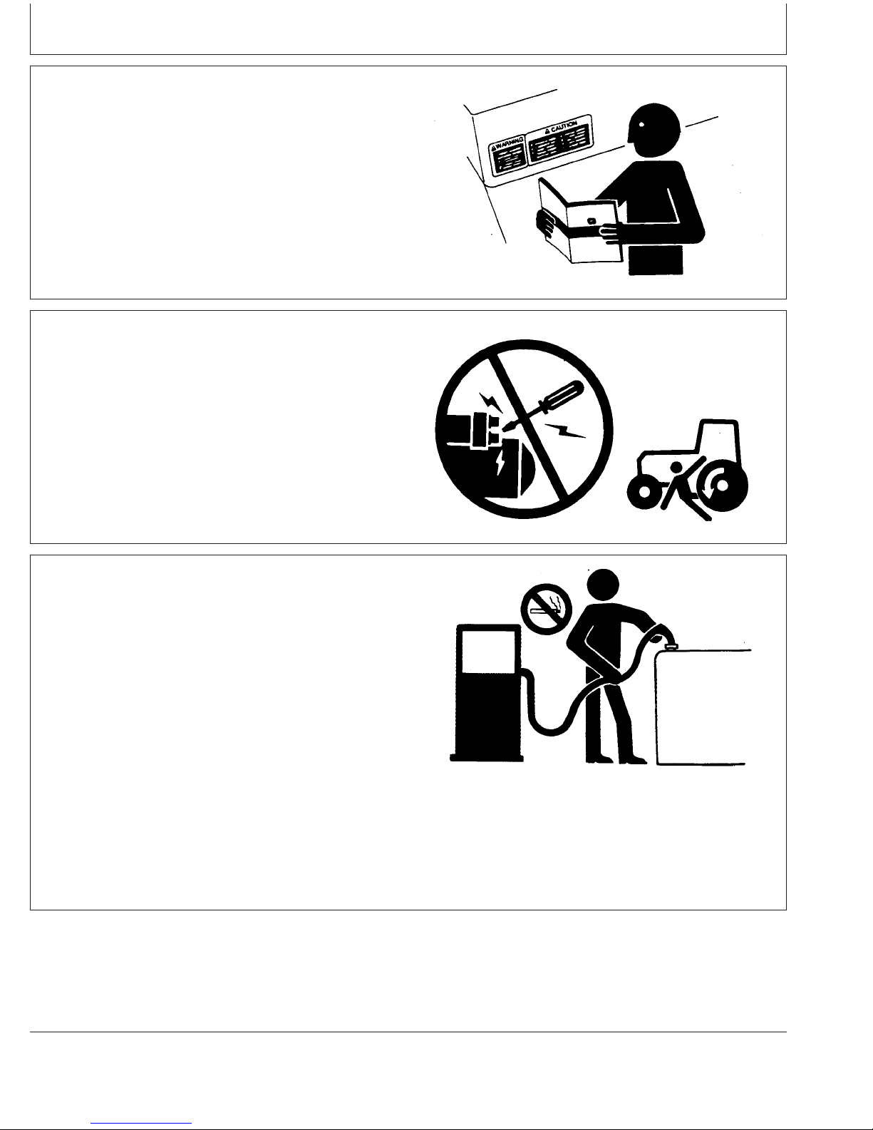
Follow Safety Instructions
Carefully read all safety messages in this manual and on
your machine safety signs. Keep safety signs in good
condition. Replace missing or damaged safety signs. Be
sure new equipment components and repair parts include
the current safety signs. Replacement safety signs are
available from your John Deere dealer.
DX,ALERT –19–29SEP98–1/1
T81389 –UN–07DEC88
TS187 –19–30SEP88
DX,SIGNAL –19–03MAR93–1/1
Learn how to operate the machine and how to use
controls properly. Do not let anyone operate without
instruction.
Keep your machine in proper working condition.
Unauthorized modifications to the machine may impair the
function and/or safety and affect machine life.
If you do not understand any part of this manual and need
assistance, contact your John Deere dealer.
05-1
TS201 –UN–23AUG88
DX,READ –19–03MAR93–1/1
110306
PN=14
Page 15
Replace Safety Signs
Replace missing or damaged safety signs. See the
machine operator’s manual for correct safety sign
placement.
Safety
Prevent Machine Runaway
Avoid possible injury or death from machinery runaway.
Do not start engine by shorting across starter terminals.
Machine will start in gear if normal circuitry is bypassed.
NEVER start engine while standing on ground. Start
engine only from operator’s seat, with transmission in
neutral or park.
Handle Fuel Safely—Avoid Fires
Handle fuel with care: it is highly flammable. Do not refuel
the machine while smoking or when near open flame or
sparks.
Always stop engine before refueling machine. Fill fuel tank
outdoors.
DX,SIGNS1 –19–04JUN90–1/1
TS201 –UN–23AUG88
TS177 –UN–11JAN89
DX,BYPAS1 –19–29SEP98–1/1
Prevent fires by keeping machine clean of accumulated
trash, grease, and debris. Always clean up spilled fuel.
05-2
TS202 –UN–23AUG88
DX,FIRE1 –19–03MAR93–1/1
110306
PN=15
Page 16

Safety
Prepare for Emergencies
Be prepared if a fire starts.
Keep a first aid kit and fire extinguisher handy.
Keep emergency numbers for doctors, ambulance service,
hospital, and fire department near your telephone.
Handle Starting Fluid Safely
Starting fluid is highly flammable.
Keep all sparks and flame away when using it. Keep
starting fluid away from batteries and cables.
To prevent accidental discharge when storing the
pressurized can, keep the cap on the container, and store
in a cool, protected location.
Do not incinerate or puncture a starting fluid container.
DX,FIRE2 –19–03MAR93–1/1
TS291 –UN–23AUG88
TS1356 –UN–18MAR92
DX,FIRE3 –19–16APR92–1/1
Handle Fluids Safely—Avoid Fires
When you work around fuel, do not smoke or work near
heaters or other fire hazards.
Store flammable fluids away from fire hazards. Do not
incinerate or puncture pressurized containers.
Make sure machine is clean of trash, grease, and debris.
Do not store oily rags; they can ignite and burn
spontaneously.
05-3
TS227 –UN–23AUG88
DX,FLAME –19–29SEP98–1/1
110306
PN=16
Page 17

Safety
Service Machines Safely
Tie long hair behind your head. Do not wear a necktie,
scarf, loose clothing, or necklace when you work near
machine tools or moving parts. If these items were to get
caught, severe injury could result.
Remove rings and other jewelry to prevent electrical
shorts and entanglement in moving parts.
Wear Protective Clothing
Wear close fitting clothing and safety equipment
appropriate to the job.
Prolonged exposure to loud noise can cause impairment
or loss of hearing.
Wear a suitable hearing protective device such as
earmuffs or earplugs to protect against objectionable or
uncomfortable loud noises.
Operating equipment safely requires the full attention of
the operator. Do not wear radio or music headphones
while operating machine.
DX,LOOSE –19–04JUN90–1/1
TS228 –UN–23AUG88
TS206 –UN–23AUG88
DX,WEAR –19–10SEP90–1/1
Protect Against Noise
Prolonged exposure to loud noise can cause impairment
or loss of hearing.
Wear a suitable hearing protective device such as
earmuffs or earplugs to protect against objectionable or
uncomfortable loud noises.
05-4
DX,NOISE –19–03MAR93–1/1
TS207 –UN–23AUG88
110306
PN=17
Page 18

Safety
Handle Chemical Products Safely
Direct exposure to hazardous chemicals can cause
serious injury. Potentially hazardous chemicals used with
John Deere equipment include such items as lubricants,
coolants, paints, and adhesives.
A Material Safety Data Sheet (MSDS) provides specific
details on chemical products: physical and health hazards,
safety procedures, and emergency response techniques.
Check the MSDS before you start any job using a
hazardous chemical. That way you will know exactly what
the risks are and how to do the job safely. Then follow
procedures and recommended equipment.
(See your John Deere dealer for MSDS’s on chemical
products used with John Deere equipment.)
Stay Clear of Rotating Drivelines
Entanglement in rotating driveline can cause serious injury
or death.
Keep master shield and driveline shields in place at all
times. Make sure rotating shields turn freely.
TS1132 –UN–26NOV90
DX,MSDS,NA –19–03MAR93–1/1
Wear close-fitting clothing. Stop the engine and be sure
PTO driveline is stopped before making adjustments,
connections, or performing any type of service on the
engine or PTO-driven equipment.
05-5
Rotating Drivelines
TS1644 –UN–22AUG95
OUO1004,0000BD8 –19–11OCT06–1/1
110306
PN=18
Page 19

Safety
Practice Safe Maintenance
Understand service procedure before doing work. Keep
area clean and dry.
Never lubricate, service, or adjust machine while it is
moving. Keep hands, feet , and clothing from
power-driven parts. Disengage all power and operate
controls to relieve pressure. Lower equipment to the
ground. Stop the engine. Remove the key. Allow machine
to cool.
Securely support any machine elements that must be
raised for service work.
Keep all parts in good condition and properly installed. Fix
damage immediately. Replace worn or broken parts.
Remove any buildup of grease, oil, or debris.
On self-propelled equipment, disconnect battery ground
cable (-) before making adjustments on electrical systems
or welding on machine.
On towed implements, disconnect wiring harnesses from
tractor before servicing electrical system components or
welding on machine.
Work In Ventilated Area
Engine exhaust fumes can cause sickness or death. If it is
necessary to run an engine in an enclosed area, remove
the exhaust fumes from the area with an exhaust pipe
extension.
If you do not have an exhaust pipe extension, open the
doors and get outside air into the area
TS218 –UN–23AUG88
DX,SERV –19–17FEB99–1/1
TS220 –UN–23AUG88
DX,AIR –19–17FEB99–1/1
05-6
110306
PN=19
Page 20

Safety
Avoid High-Pressure Fluids
Escaping fluid under pressure can penetrate the skin
causing serious injury.
Avoid the hazard by relieving pressure before
disconnecting hydraulic or other lines. Tighten all
connections before applying pressure.
Search for leaks with a piece of cardboard. Protect hands
and body from high pressure fluids.
If an accident occurs, see a doctor immediately. Any fluid
injected into the skin must be surgically removed within a
few hours or gangrene may result. Doctors unfamiliar with
this type of injury should reference a knowledgeable
medical source. Such information is available from Deere
& Company Medical Department in Moline, Illinois, U.S.A.
X9811 –UN–23AUG88
Avoid Heating Near Pressurized Fluid Lines
Flammable spray can be generated by heating near
pressurized fluid lines, resulting in severe burns to
yourself and bystanders. Do not heat by welding,
soldering, or using a torch near pressurized fluid lines or
other flammable materials. Pressurized lines can
accidentally burst when heat goes beyond the immediate
flame area.
DX,FLUID –19–03MAR93–1/1
TS953 –UN–15MAY90
DX,TORCH –19–10DEC04–1/1
05-7
110306
PN=20
Page 21

Safety
Remove Paint Before Welding or Heating
Avoid potentially toxic fumes and dust.
Hazardous fumes can be generated when paint is heated
by welding, soldering, or using a torch.
Remove paint before heating:
• Remove paint a minimum of 100 mm (4 in.) from area
to be affected by heating. If paint cannot be removed,
wear an approved respirator before heating or welding.
• If you sand or grind paint, avoid breathing the dust.
Wear an approved respirator.
• If you use solvent or paint stripper, remove stripper with
soap and water before welding. Remove solvent or
paint stripper containers and other flammable material
from area. Allow fumes to disperse at least 15 minutes
before welding or heating.
Do not use a chlorinated solvent in areas where welding
will take place.
TS220 –UN–23AUG88
Do all work in an area that is well ventilated to carry toxic
fumes and dust away.
Dispose of paint and solvent properly.
Service Cooling System Safely
Explosive release of fluids from pressurized cooling
system can cause serious burns.
Shut off engine. Only remove filler cap when cool enough
to touch with bare hands. Slowly loosen cap to first stop
to relieve pressure before removing completely.
DX,PAINT –19–24JUL02–1/1
TS281 –UN–23AUG88
DX,RCAP –19–04JUN90–1/1
05-8
110306
PN=21
Page 22
Safety
Install Fan Guards
Rotating cooling system fans can cause serious injury.
Keep fan guards in place at all times during engine
operation. Wear close fitting clothes. Stop the engine and
be sure fan is stopped before making adjustments or
connections, or cleaning near the front of the engine.
Avoid Hot Parts
Avoid skin contact with exhaust manifolds, turbochargers
and mufflers. Keep flammable materials clear of the
turbocharger.
External dry exhaust parts become very hot during
operation. Turbochargers may reach temperatures as high
as 500°C (932°F) under full load, and naturally aspired
exhaust manifolds may reach 600°C (1112°F) under full
load. This may ignite paper, cloth or wooden materials.
Parts on engines that have been at full load and reduced
to no load idle will maintain approximately 150°C (302°F).
Rotating Fan
TS677 –UN–21SEP89
OUOD006,000009D –19–11OCT06–1/1
TS271 –UN–23AUG88
Hot Surface
05-9
OUOD006,000009E –19–04DEC02–1/1
110306
PN=22
Page 23
Safety
Avoid Harmful Asbestos Dust
Avoid breathing dust that may be generated when
handling components containing asbestos fibers. Inhaled
asbestos fibers may cause lung cancer.
Components in products that may contain asbestos fibers
are brake pads, brake band and lining assemblies, clutch
plates, and some gaskets. The asbestos used in these
components is usually found in a resin or sealed in some
way. Normal handling is not hazardous as long as
airborne dust containing asbestos is not generated.
Avoid creating dust. Never use compressed air for
cleaning. Avoid brushing or grinding material containing
asbestos. When servicing, wear an approved respirator. A
special vacuum cleaner is recommended to clean
asbestos. If not available, apply a mist of oil or water on
the material containing asbestos.
Keep bystanders away from the area.
TS220 –UN–23AUG88
Prevent Battery Explosions
Keep sparks, lighted matches, and open flame away from
the top of battery. Battery gas can explode.
Never check battery charge by placing a metal object
across the posts. Use a volt-meter or hydrometer.
Do not charge a frozen battery; it may explode. Warm
battery to 16°C (60°F).
DX,DUST –19–15MAR91–1/1
TS204 –UN–23AUG88
DX,SPARKS –19–03MAR93–1/1
05-10
110306
PN=23
Page 24

Handling Batteries Safely
CAUTION: Battery gas can explode. Keep
sparks and flames away from batteries. Use a
flashlight to check battery electrolyte level.
Never check battery charge by placing a metal
object across the posts. Use a voltmeter or
hydrometer.
Safety
Always remove grounded (—) battery clamp
first and replace it last.
CAUTION: Sulfuric acid in battery electrolyte is
poisonous. It is strong enough to burn skin, eat
holes in clothing, and cause blindness if
splashed into eyes.
Avoid the hazard by:
1. Filling batteries in a well-ventilated area.
2. Wearing eye protection and rubber gloves.
3. Avoiding breathing fumes when electrolyte is
added.
4. Avoiding spilling or dripping electrolyte.
5. Using proper jump start procedure.
If you spill acid on yourself:
1. Flush your skin with water.
2. Apply baking soda or lime to help neutralize
the acid.
3. Flush your eyes with water for 15—30
minutes. Get medical attention immediately.
Explosion
TS204 –UN–23AUG88
If acid is swallowed:
1. Do not induce vomiting.
2. Drink large amounts of water or milk, but do
not exceed2L(2qt.).
3. Get medical attention immediately.
WARNING: Battery posts, terminals, and related
accessories contain lead and lead compounds, chemicals
known to the State of California to cause cancer and
reproductive harm. Wash hands after handling.
05-11
Acid
TS203 –UN–23AUG88
DPSG,OUO1004,2758 –19–11OCT06–1/1
110306
PN=24
Page 25

Safety
Protect Against High Pressure Spray
Spray from high pressure nozzles can penetrate the skin
and cause serious injury. Keep spray from contacting
hands or body.
If an accident occurs, see a doctor immediately. Any high
pressure spray injected into the skin must be surgically
removed within a few hours or gangrene may result.
Doctors unfamiliar with this type of injury should reference
a knowledgeable medical source. Such information is
available from Deere & Company Medical Department in
Moline, Illinois, U.S.A.
Use Proper Lifting Equipment
TS1343 –UN–18MAR92
DX,SPRAY –19–16APR92–1/1
Lifting heavy components incorrectly can cause severe
injury or machine damage.
Follow recommended procedure for removal and
installation of components in the manual.
Use Proper Tools
Use tools appropriate to the work. Makeshift tools and
procedures can create safety hazards.
Use power tools only to loosen threaded parts and
fasteners.
For loosening and tightening hardware, use the correct
size tools. DO NOT use U.S. measurement tools on
metric fasteners. Avoid bodily injury caused by slipping
wrenches.
DX,LIFT –19–04JUN90–1/1
TS226 –UN–23AUG88
TS779 –UN–08NOV89
Use only service parts meeting John Deere specifications.
05-12
DX,REPAIR –19–17FEB99–1/1
110306
PN=25
Page 26
Safety
Dispose of Waste Properly
Improperly disposing of waste can threaten the
environment and ecology. Potentially harmful waste used
with John Deere equipment include such items as oil, fuel,
coolant, brake fluid, filters, and batteries.
Use leakproof containers when draining fluids. Do not use
food or beverage containers that may mislead someone
into drinking from them.
Do not pour waste onto the ground, down a drain, or into
any water source.
Air conditioning refrigerants escaping into the air can
damage the Earth’s atmosphere. Government regulations
may require a certified air conditioning service center to
recover and recycle used air conditioning refrigerants.
Inquire on the proper way to recycle or dispose of waste
from your local environmental or recycling center, or from
your John Deere dealer.
TS1133 –UN–26NOV90
DX,DRAIN –19–03MAR93–1/1
05-13
110306
PN=26
Page 27

Diesel Fuel
Fuels, Lubricants, and Coolant
Consult your local fuel distributor for properties of the
diesel fuel available in your area.
In general, diesel fuels are blended to satisfy the low
temperature requirements of the geographical area in
which they are marketed.
Diesel fuels specified to EN 590 or ASTM D975 are
recommended.
Required fuel properties
In all cases, the fuel shall meet the following
properties:
Cetane number of 45 minimum. Cetane number
greater than 50 is preferred, especially for
temperatures below -20°C (-4°F) or elevations above
1500 m (5000 ft).
Cold Filter Plugging Point (CFPP) below the
expected low temperature OR Cloud Point at least
5°C(9°F) below the expected low temperature.
Fuel lubricity should pass a minimum level of 3100
grams as measured by ASTM D6078 or maximum
scar diameter of 0.45 mm as measured by ASTM
D6079 or ISO 12156-1.
Sulfur content:
• Diesel fuel quality and fuel sulfur content must
comply with all existing emissions regulations for the
area in which the engine operates.
• Use of diesel fuel with sulfur content less than
0.10% (1000 ppm) is STRONGLY recommended.
• Use of diesel fuel with sulfur content 0.10% (1000
ppm to 0.50% (5000 ppm) may result in REDUCED
oil and filter change intervals.
• BEFORE using diesel fuel with sulfur content greater
than 0.50% (5000 ppm), contact your John Deere
dealer.
• DO NOT use diesel fuel with sulfur content greater
than 1.0%.
IMPORTANT: Do not mix used diesel engine oil or
any other type of lubricating oil with
diesel fuel.
IMPORTANT: Improper fuel additive usage may
cause damage on fuel injection
equipment of diesel engines.
Lubricity of Diesel Fuel
Most diesel fuels manufactured in the United States,
Canada, and the European Union have adequate
lubricity to ensure proper operation and durability of
fuel injection system components. However, diesel
fuels manufactured in some areas of the world may
lack the necessary lubricity.
IMPORTANT: Make sure the diesel fuel used in
your machine demonstrates good
lubricity characteristics.
DX,FUEL1 –19–17NOV05–1/1
Fuel lubricity should pass a minimum load level of
3100 grams as measured by ASTM D6078 or a
maximum scar diameter of 0.45 mm as measured by
ASTM D6079 or ISO 12156-1.
If fuel of low or unknown lubricity is used, add John
Deere PREMIUM DIESEL FUEL CONDITIONER (or
equivalent) at the specified concentration.
DX,FUEL5 –19–27OCT05–1/1
10-1
110306
PN=27
Page 28

Handling and Storing Diesel Fuel
Fuels, Lubricants, and Coolant
CAUTION: Handle fuel carefully. Do not fill
the fuel tank when engine is running.
DO NOT smoke while you fill the fuel tank or
service the fuel system.
Fill the fuel tank at the end of each day’s operation to
prevent water condensation and freezing during cold
weather.
Keep all storage tanks as full as practicable to
minimize condensation.
Ensure that all fuel tank caps and covers are installed
properly to prevent moisture from entering.
Monitor water content of the fuel regularly.
When using bio-diesel fuel, the fuel filter may require
more frequent replacement due to premature plugging.
Check engine oil level daily prior to starting engine. A
rising oil level may indicate fuel dilution of the engine
oil.
IMPORTANT: The fuel tank is vented through the
filler cap. If a new filler cap is
required, always replace it with an
original vented cap.
When fuel is stored for an extended period or if there
is a slow turnover of fuel, add a fuel conditioner to
stabilize the fuel and prevent water condensation.
Contact your fuel supplier for recommendations.
DX,FUEL4 –19–19DEC03–1/1
Testing Diesel Fuel
DIESELSCAN is a John Deere fuel analysis program
that can be used to monitor the quality of your fuel. The
DIESELSCAN analysis verifies fuel type, cleanliness,
water content, suitability for cold weather operation, and
whether the fuel meets specifications.
Check with your John Deere dealer for availability of
DIESELSCAN kits.
DIESELSCAN is a trademark of Deere & Company
DX,FUEL6 –19–14NOV05–1/1
10-2
110306
PN=28
Page 29

Bio-Diesel Fuel
Fuels, Lubricants, and Coolant
Consult your local fuel distributor for properties of the
bio-diesel fuel available in your area.
Bio-diesel fuels may be used ONLY if the bio-diesel
fuel properties meet the latest edition of ASTM D6751,
EN 14214, or equivalent specification.
It is recommended to purchase bio-diesel fuel blended
with B100 from a BQ-9000 Accredited Producer or a
BQ-9000 Certified Marketer as recommended by the
National Bio-diesel Board.
The maximum allowable bio-diesel concentration is a
5% blend (also known as B5) in petroleum diesel fuel.
It has been found that bio-diesel fuels may improve
lubricity in concentrations up to this 5% blend.
When using a blend of bio-diesel fuel, the engine oil
level must be checked daily when the air temperature
is –10°C (14°F) or lower. If oil becomes diluted with
fuel, shorten oil change intervals accordingly.
IMPORTANT: Raw pressed vegetable oils are NOT
acceptable for use as fuel in any
concentration in John Deere
engines.
leaving deposits on injectors and in
the combustion chamber.
A major environmental benefit of bio-diesel fuel is its
ability to biodegrade. This makes proper storage and
handling of bio-diesel fuel especially important. Areas
of concern include:
• Quality of new fuel
• Water content of the fuel
• Problems due to aging of the fuel
Potential problems resulting from deficiencies in the
above areas when using bio-diesel fuel in
concentrations above 5% may lead to the following
symptoms:
• Power loss and deterioration of performance
• Fuel leakage
• Corrosion of fuel injection equipment
• Coked and/or blocked injector nozzles, resulting in
engine misfire
• Filter plugging
• Lacquering and/or seizure of internal components
• Sludge and sediments
• Reduced service life of engine components
These oils do not burn completely,
and will cause engine failure by
Consult your fuel supplier for additives to improve
storage and performance of bio-diesel fuels.
DX,FUEL7 –19–14NOV05–1/1
10-3
110306
PN=29
Page 30
Fuels, Lubricants, and Coolant
Aviation (Jet) Fuels
Aviation (jet) fuels may be used with the following
restrictions.
Type Comments
Jet A Lower viscosity and density than base No. 2-D diesel
Jet A-1 Lower viscosity and density than base No. 2-D diesel
Jet B Not Recommended.Lower density and extremely
JP-4 Not Recommended.Lower density and extremely
JP-5 Lower viscosity and density than base No. 2-D diesel
JP-7 Lower viscosity and density than base No. 2-D diesel
JP-8 Lower viscosity and density than base No. 2-D diesel
fuel. Power loss up to 10% can be expected.
fuel. Power loss up to 10% can be expected.
low viscosity compared to base No. 2-D diesel fuel.
Power loss up to 14% can be expected.
low viscosity compared to base No. 2-D diesel fuel.
Power loss up to 12% can be expected.
fuel. Power loss up to 9% can be expected.
fuel. Power loss up to 10% can be expected.
fuel. Power loss up to 10% can be expected.
Burner Fuels
Burner fuels, like kerosene, may be used with the
following restrictions.
Type Comments
No.2 Higher density and specific gravity than base No. 2-D
diesel fuel. Power increase up to 3% can be
expected.
No.1 Lower viscosity than base No. 2-D diesel fuel. Power
loss up to 2% can be expected.
10-4
OURGP12,000003F –19–07JUL04–1/1
OURGP12,0000040 –19–07JUL04–1/1
110306
PN=30
Page 31

Fuels, Lubricants, and Coolant
Minimizing the Effect of Cold Weather on Diesel Engines
John Deere diesel engines are designed to operate
effectively in cold weather.
However, for effective starting and cold weather
operation, a little extra care is necessary. The
information below outlines steps that can minimize the
effect that cold weather may have on starting and
operation of your engine. See your John Deere dealer
for additional information and local availability of cold
weather aids
Use Winter Grade Fuel
When temperatures fall below 5°C (40°F), winter grade
fuel (Grade No. 1-D fuel in North America) is best
suited for cold weather operation. Winter grade fuel
has a lower cloud point and a lower pour point.
Cloud point is the temperature at which wax will begin
to form in the fuel and this wax causes fuel filters to
plug. Pour point is the temperature at which fuel
begins to thicken and becomes more resistant to flow
through fuel pumps and lines.
NOTE: On an average, winter grade fuel has a lower
BTU (heat content) rating. Using winter grade
fuel may reduce power and fuel efficiency, but
should not cause any other engine
performance effects. Check the grade of fuel
being used before troubleshooting for low
power complaints in cold weather operation.
CAUTION: Do not use any starting fluid with
an engine equipped with glow plugs
Coolant Heater
An engine block heater (coolant heater) is an available
option to aid cold weather starting.
Seasonal Viscosity Oil and Proper Coolant
Concentration
Use seasonal grade viscosity engine oil based ion the
expected air temperature range between oil changes
and proper concentration of low silicate antifreeze as
recommended. (See DIESEL ENGINE OIL and
ENGINE COOLANT requirements this section.)
Diesel Fuel Flow Additive
Use John Deere Premium Diesel Fuel Conditioner
(Winter) or equivalent to treat fuel during the cold
weather season. This winter formulation is a
combination diesel fuel conditioner and anti-gel
additive.
IMPORTANT: Treat fuel when outside temperature
drops below 0°C (32°F). For best
results, use with untreated fuel.
Follow all recommended instructions
on label.
Air Intake Heater
An air intake heater is an available option to aid cold
weather starting.
CAUTION: Do not use any starting fluid with
an air intake heater.
Starting Fluid
A starting fluid port on the intake is available to aid
cold weather starting.
Winterfronts
Use of fabric, cardboard , or solid winterfronts is not
recommended with any John Deere engine. Their use
can result in excessive engine coolant, oil, and charge
air temperatures. This can lead to reduced engine life,
loss of power and poor fuel economy. Winterfronts
may also put abnormal stress on fan and fan drive
components potentially causing premature failures.
Continued on next page
DX,FUEL10 –19–16DEC05–1/2
10-5
110306
PN=31
Page 32

Fuels, Lubricants, and Coolant
If winterfronts are used, they should never totally close
off the grill frontal area. Approximately 25% area in the
center of the grill should remain open at all times. At
no time should the air blockage device be applied
directly to the radiator core.
Radiator Shutters
If equipped with a thermostatically controlled radiator
shutter system, this system should be regulated in
such a way that the shutters are completely open by
Diesel Engine Break-In Oil
New engines are filled at the factory with John Deere
ENGINE BREAK-IN OIL. During the break-in period,
add John Deere ENGINE BREAK-IN OIL as needed to
maintain the specified oil level.
Change the oil and filter after the first 100 hours of
operation of a new or rebuilt engine.
After engine overhaul, fill the engine with John Deere
ENGINE BREAK-IN OIL.
If John Deere ENGINE BREAK-IN OIL is not available,
use a diesel engine oil meeting one of the following
during the first 100 hours of operation:
• API Service Classification CE
• API Service Classification CD
• API Service Classification CC
• ACEA Oil Sequence E2
• ACEA Oil Sequence E1
the time the coolant reaches 93°C (200°F) to prevent
excessive intake manifold temperatures. Manually
controlled systems are not recommended.
If air-to-air aftercooling is used, the shutters must be
completely open by the time the intake manifold air
temperature reaches the maximum allowable
temperature out of the charge air cooler.
For more information, see your John Deere dealer.
DX,FUEL10 –19–16DEC05–2/2
After the break-in period, use John Deere PLUS-50
or other diesel engine oil as recommended in this
manual.
IMPORTANT: Do not use PLUS-50 oil or engine
oils meeting any of the following
during the first 100 hours of
operation of a new or rebuilt engine:
API CJ-4 ACEA E7
API CI-4 PLUS ACEA E6
API CI-4 ACEA E5
API CH-4 ACEA E4
API CG-4 ACEA E3
API CF-4
API CF-2
API CF
These oils will not allow the engine
to break-in properly.
PLUS-50 is a trademark of Deere & Company.
10-6
DX,ENOIL4 –19–13SEP06–1/1
110306
PN=32
Page 33

Fuels, Lubricants, and Coolant
Diesel Engine Oil
Use oil viscosity based on the expected air temperature
range during the period between oil changes.
John Deere PLUS-50 oil is preferred.
Oils meeting one of the following specifications are also
recommended:
• ACEA Oil Sequence E7
• ACEA Oil Sequence E6
• ACEA Oil Sequence E5
• ACEA Oil Sequence E4
Extended service intervals may apply when John Deere
PLUS-50, ACEA E7, ACEA E6, ACEA E5, or ACEA E4
engine oils are used. Consult your John Deere dealer for
more information.
Other oils may be used if they meet one or more of the
following:
• John Deere TORQ-GARD SUPREME
• API Service Category CJ-4
• API Service Category CI-4 PLUS
• API Service Category CI-4
• API Service Category CH-4
• API Service Category CG-4
• API Service Category CF-4
• ACEA Oil Sequence E3
• ACEA Oil Sequence E2
If oils meeting API CG-4, API CF-4, or ACEA E2 are
used, reduce the service interval by 50%.
Multi-viscosity diesel engine oils are preferred.
Diesel fuel quality and fuel sulfur content must comply
with all existing emissions regulations for the area in
which the engine operates.
If diesel fuel with sulfur content greater than 0.50% (5000
ppm) is used, reduce the service interval by 50%.
Oil Viscosities for Air Temperature Ranges
TS1681 –UN–09OCT06
PLUS-50 is a trademark of Deere & Company
TORQ-GARD SUPREME is a trademark of Deere & Company
Continued on next page
10-7
DX,ENOIL –19–13SEP06–1/2
110306
PN=33
Page 34

Fuels, Lubricants, and Coolant
DO NOT use diesel fuel with sulfur content greater than
1.00% (10 000 ppm).
Extended Diesel Engine Oil Service Intervals
DX,ENOIL –19–13SEP06–2/2
When John Deere PLUS-50 oil is used with the
specified John Deere filter, the service interval for
engine oil and filter changes may be increased by 50%
but not to exceed a maxium of 500 hours.
When ACEA E7, ACEA E6, ACEA E5, or ACEA E4
oils are used with specified John Deere filter, use
engine oil analysis to determine if the service interval
for engine oil and filter changes may be increased by a
maximum of 50% but not to exceed 500 hours.
If John Deere PLUS-50, ACEA E7, ACEA E6, ACEA
E5, or ACEA E4 oils are used with other than the
PLUS-50 is a trademark of Deere & Company
TORQ-GARD SUPREME is a trademark of Deere & Company
specified John Deere filter, change the engine oil and
filter at the normal service interval.
If John Deere TORQ-GARD SUPREME, API CJ-4,
API CI-4 PLUS, API CI-4, API CH-4, or ACEA E3 oils
are used, change the engine oil and filter at the normal
service interval.
If API CG-4, API CF-4, or ACEA E2 oils are used,
change the engine oil and filter at 50% of the normal
service interval.
DX,ENOIL6 –19–13SEP06–1/1
Mixing of Lubricants
In general, avoid mixing different brands or types of oil.
Oil manufacturers blend additives in their oils to meet
certain specifications and performance requirements.
Mixing different oils can interfere with the proper
functioning of these additives and degrade lubricant
performance.
Consult your John Deere dealer to obtain specific
information and recommendations.
DX,LUBMIX –19–18MAR96–1/1
10-8
110306
PN=34
Page 35
Fuels, Lubricants, and Coolant
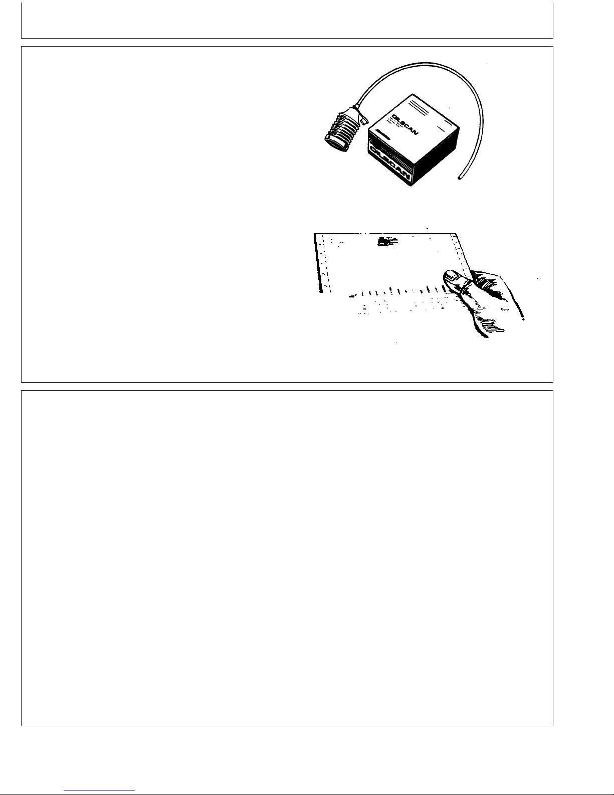
OILSCANand COOLSCAN
OILSCANand COOLSCAN are John Deere sampling
programs to help you monitor machine performance and
identify potential problems before they cause serious
damage.
Oil and coolant samples should be taken from each
system prior to its recommended change interval.
Check with your John Deere dealer for the availability of
OILSCAN and COOLSCAN kits.
T6828AB –UN–15JUN89T6829AB –UN–18OCT88
OILSCAN is a registered trademark of Deere & Company.
COOLSCAN is a trademark of Deere & Company.
Alternative and Synthetic Lubricants
Conditions in certain geographical areas may require
lubricant recommendations different from those printed in
this manual.
Some John Deere brand coolants and lubricants may not
be available in your location.
Consult your John Deere dealer to obtain information and
recommendations.
Synthetic lubricants may be used if they meet the
performance requirements as shown in this manual.
The temperature limits and service intervals shown in this
manual apply to both conventional and synthetic oils.
Re-refined base stock products may be used if the
finished lubricant meets the performance requirements.
DX,OILSCAN –19–02DEC02–1/1
10-9
DX,ALTER –19–15JUN00–1/1
110306
PN=35
Page 36

Lubricant Storage
Fuels, Lubricants, and Coolant
Your equipment can operate at top efficiency only
when clean lubricants are used.
Use clean containers to handle all lubricants.
Whenever possible, store lubricants and containers in
an area protected from dust, moisture, and other
contamination. Store containers on their side to avoid
water and dirt accumulation.
Oil Filters
Filtration of oils is critical to proper operation and
lubrication.
Make certain that all containers are properly marked to
identify their contents.
Properly dispose of all old containers and any residual
lubricant they may contain.
DX,LUBST –19–18MAR96–1/1
Always change filters regularly as specified in this manual.
Use filters meeting John Deere performance
specifications.
DX,FILT –19–18MAR96–1/1
10-10
110306
PN=36
Page 37

Fuels, Lubricants, and Coolant
Grease
Use grease based on NLGI consistency numbers and the
expected air temperature range during the service interval.
John Deere SD POLYUREA GREASE is preferred.
The following greases are also recommended
• John Deere HD LITHIUM COMPLEX GREASE
• John Deere HD WATER RESISTANT GREASE
• John Deere GREASE-GARD
Other greases may be used if they meet the following:
NLGI Performance Classification GC-LB
IMPORTANT: Some types of grease thickeners are
not compatible with others. Consult
your grease supplier before mixing
different types of grease
TS1673 –UN–31OCT03
GREASE-GARD is a trademark of Deere & Company
DX,GREA1 –19–07NOV03–1/1
10-11
110306
PN=37
Page 38

Diesel Engine Coolant
Fuels, Lubricants, and Coolant
The engine cooling system is filled to provide
year-round protection against corrosion and cylinder
liner pitting, and winter freeze protection to -37°C
(-34°F). If protection at lower temperatures is required,
consult your John Deere dealer for recommendations.
John Deere COOL-GARD Prediluted Coolant is
preferred for service.
John Deere COOL-GARD Prediluted Coolant is
available in a concentration of either 50% ethylene
glycol or 55% propylene glycol.
Additional recommended coolants
The following engine coolant is also recommended:
• John Deere COOL-GARD Coolant Concentrate in a
40% to 60% mixture of concentrate with quality
water.
John Deere COOL-GARD coolants do not require use
of supplemental coolant additives, except for periodic
replenishment of additives during the drain interval.
Other fully formulated coolants
Other fully formulated low silicate ethylene or
propylene glycol base coolants for heavy-duty engines
may be used if they meet one of the following
specifications:
Other low silicate ethylene glycol base coolants for
heavy-duty engines may also be used if they meet one
of the following specifications:
• ASTM D4985 ethylene glycol base prediluted (50%)
coolant
• ASTM D4985 ethylene glycol base coolant
concentrate in a 40% to 60% mixture of concentrate
with quality water
Coolants meeting ASTM D4985 require an initial
charge of supplemental coolant additives, formulated
for protection of heavy duty diesel engines against
corrosion and cylinder liner erosion and pitting. They
also require periodic replenishment of additives during
the drain interval.
Other coolants
It is possible that neither John Deere COOL-GARD nor
coolants meeting one of the coolant standards listed
above is available in the geographical area where
service is performed. If these coolants are unavailable,
use a coolant concentrate or prediluted coolant with a
quality additive package that provides cylinder liner
cavitation protection and protects the cooling system
metals (cast iron, aluminum alloys, and copper alloys
such as brass) from corrosion.
The additive package must be part of one of the
following coolant mixtures:
• ASTM D6210 prediluted (50%) coolant
• ASTM D6210 coolant concentrate in a 40% to 60%
mixture of concentrate with quality water
Coolants meeting ASTM D6210 do not require use of
supplemental coolant additives, except for periodic
replenishment of additives during the drain interval.
Coolants requiring supplemental coolant additives
COOL-GARD is a trademark of Deere & Company
• ethylene glycol or propylene glycol base prediluted
(40% to 60%) coolant
• ethylene glycol or propylene glycol base coolant
concentrate in a 40% to 60% mixture of concentrate
with quality water
Water quality
Continued on next page
DX,COOL3 –19–27OCT05–1/2
10-12
110306
PN=38
Page 39

Fuels, Lubricants, and Coolant
Water quality is important to the performance of the
cooling system. Distilled, deionized, or demineralized
water is recommended for mixing with ethylene glycol
and propylene glycol base engine coolant concentrate.
IMPORTANT: Do not use cooling system sealing
additives or antifreeze that contains
sealing additives.
Drain Intervals for Diesel Engine Coolant
Drain the factory fill engine coolant, flush the cooling
system, and refill with new coolant after the first 3 years
or 3000 hours of operation.
Subsequent drain intervals are determined by the coolant
used for service. At each interval, drain the coolant, flush
the cooling system, and refill with new coolant.
IMPORTANT: Do not mix ethylene glycol and
propylene glycol base coolants.
DX,COOL3 –19–27OCT05–2/2
When John Deere COOL-GARD is used, the drain
interval may be extended to 5 years or 5000 hours of
operation, provided that the coolant is tested annually
AND additives are replenished, as needed, by adding a
supplemental coolant additive.
If John Deere COOL-GARD is used but the coolant is not
tested OR additives are not replenished by adding a
supplemental coolant additive, the drain interval is 3 years
or 3000 hours of operation
If COOL-GARD is not used, the drain interval is reduced
to 2 years or 2000 hours of operation.
COOL-GARD is a trademark of Deere & Company
DX,COOL11 –19–19DEC03–1/1
10-13
110306
PN=39
Page 40

Fuels, Lubricants, and Coolant
Additional Information About Diesel Engine Coolants and Supplemental Coolant
Additives
Engine coolants are a combination of three chemical
components: ethylene glycol or propylene glycol
antifreeze, inhibiting coolant additives, and quality
water.
Coolant specifications
Some products, including John Deere COOL-GARD
Prediluted Coolant, are fully formulated coolants that
contain all three components in their correct
concentrations. Do not add an initial charge of
supplemental coolant additives to these fully
formulated products.
Coolants meeting ASTM D6210 do not require an
initial charge of supplemental coolant additives.
Some coolant concentrates, including John Deere
COOL-GARD Coolant Concentrate, contain both glycol
antifreeze and inhibiting coolant additives. Mix these
products with quality water, but do not add an initial
charge of supplemental coolant additives.
Coolants meeting ASTM D4985 require an initial
charge of supplemental coolant additives.
Replenish coolant additives
simple mixture of ethylene glycol or propylene glycol
and water will not give adequate protection.
Use of supplemental coolant additives reduces
corrosion, erosion, and pitting. These chemicals
reduce the number of vapor bubbles in the coolant and
help form a protective film on cylinder liner surfaces.
This film acts as a barrier against the harmful effects
of collapsing vapor bubbles.
Avoid automotive-type coolants
Never use automotive-type coolants (such as those
meeting ASTM D3306). These coolants do not contain
the correct additives to protect heavy-duty diesel
engines. They often contain a high concentration of
silicates and may damage the engine or cooling
system.
Water quality
Water quality is important to the performance of the
cooling system. Distilled, deionized, or demineralized
water is recommended for mixing with ethylene glycol
and propylene glycol base engine coolant concentrate.
All water used in the cooling system should meet the
following minimum specifications for quality:
The concentration of coolant additives is gradually
depleted during engine operation. Periodic
replenishment of inhibitors is required, even when
John Deere COOL-GARD or another fully formulated
coolant is used. Follow the recommendations in this
manual for the use of supplemental coolant additives.
Why use supplemental coolant additives?
Operating without proper coolant additives will result in
increased corrosion, cylinder liner erosion and pitting,
and other damage to the engine and cooling system. A
COOL-GARD is a trademark of Deere & Company
Chlorides <40 mg/L
Sulfates <100 mg/L
Total dissolved solids <340 mg/L
Total hardness <170 mg/L
pH 5.5 to 9.0
Freeze protection
The relative concentrations of glycol and water in the
engine coolant determine its freeze protection limit.
Continued on next page
DX,COOL7 –19–19DEC03–1/2
10-14
110306
PN=40
Page 41

Fuels, Lubricants, and Coolant
Ethylene Glycol Freeze Protection Limit
40% -24°C (-12°F)
50% -37°C (-34°F)
60% -52°C (-62°F)
Propylene Glycol Freeze Protection Limit
40% -21°C (-6°F)
50% -33°C (-27°F)
60% -49°C (-56°F)
Supplemental Coolant Additives
The concentration of coolant additives is gradually
depleted during engine operation. For all
recommended coolants, replenish additives between
drain intervals by adding a supplemental coolant
additive every 12 months or as determined necessary
by coolant testing.
John Deere COOLANT CONDITIONER is
recommended as a supplemental coolant additive in
John Deere engines.
IMPORTANT: Do not add a supplemental coolant
additive when the cooling system is
drained and refilled with John
DeereCOOL-GARD.
DO NOT use a coolant-water mixture greater than
60% ethylene glycol or 60% propylene glycol.
DX,COOL7 –19–19DEC03–2/2
If other coolants are used, consult the coolant supplier
and follow the manufacturer’s recommendation for use
of supplemental coolant additives.
The use of non-recommended supplemental coolant
additives may result in additive drop-out and gelation
of the coolant.
Add the manufacturer’s recommended concentration of
supplemental coolant additive. DO NOT add more than
the recommended amount.
COOL-GARD is a trademark of Deere & Company
10-15
DX,COOL4 –19–07NOV03–1/1
110306
PN=41
Page 42
Fuels, Lubricants, and Coolant
Additional Information About Diesel Engine Coolants and Supplemental Coolant
Additives
Engine coolants are a combination of three chemical
components: ethylene glycol or propylene glycol
antifreeze, inhibiting coolant additives, and quality
water.
Coolant specifications
Some products, including John Deere COOL-GARD
Prediluted Coolant, are fully formulated coolants that
contain all three components in their correct
concentrations. Do not add an initial charge of
supplemental coolant additives to these fully
formulated products.
Coolants meeting ASTM D6210 do not require an
initial charge of supplemental coolant additives.
Some coolant concentrates, including John Deere
COOL-GARD Coolant Concentrate, contain both glycol
antifreeze and inhibiting coolant additives. Mix these
products with quality water, but do not add an initial
charge of supplemental coolant additives.
Coolants meeting ASTM D4985 require an initial
charge of supplemental coolant additives.
Replenish coolant additives
simple mixture of ethylene glycol or propylene glycol
and water will not give adequate protection.
Use of supplemental coolant additives reduces
corrosion, erosion, and pitting. These chemicals
reduce the number of vapor bubbles in the coolant and
help form a protective film on cylinder liner surfaces.
This film acts as a barrier against the harmful effects
of collapsing vapor bubbles.
Avoid automotive-type coolants
Never use automotive-type coolants (such as those
meeting ASTM D3306). These coolants do not contain
the correct additives to protect heavy-duty diesel
engines. They often contain a high concentration of
silicates and may damage the engine or cooling
system.
Water quality
Water quality is important to the performance of the
cooling system. Distilled, deionized, or demineralized
water is recommended for mixing with ethylene glycol
and propylene glycol base engine coolant concentrate.
All water used in the cooling system should meet the
following minimum specifications for quality:
The concentration of coolant additives is gradually
depleted during engine operation. Periodic
replenishment of inhibitors is required, even when
John Deere COOL-GARD or another fully formulated
coolant is used. Follow the recommendations in this
manual for the use of supplemental coolant additives.
Why use supplemental coolant additives?
Operating without proper coolant additives will result in
increased corrosion, cylinder liner erosion and pitting,
and other damage to the engine and cooling system. A
COOL-GARD is a trademark of Deere & Company
Chlorides <40 mg/L
Sulfates <100 mg/L
Total dissolved solids <340 mg/L
Total hardness <170 mg/L
pH 5.5 to 9.0
Freeze protection
The relative concentrations of glycol and water in the
engine coolant determine its freeze protection limit.
Continued on next page
DX,COOL7 –19–19DEC03–1/2
10-16
110306
PN=42
Page 43

Fuels, Lubricants, and Coolant
Ethylene Glycol Freeze Protection Limit
40% -24°C (-12°F)
50% -37°C (-34°F)
60% -52°C (-62°F)
Propylene Glycol Freeze Protection Limit
40% -21°C (-6°F)
50% -33°C (-27°F)
60% -49°C (-56°F)
Testing Diesel Engine Coolant
Testing Diesel Engine Coolant
Maintaining adequate concentrations of glycol and
inhibiting additives in the coolant is critical to protect
the engine and cooling system against freezing,
corrosion, and cylinder liner erosion and pitting.
Test the coolant solution at intervals of 12 months or
less and whenever excessive coolant is lost through
leaks or overheating.
DO NOT use a coolant-water mixture greater than
60% ethylene glycol or 60% propylene glycol.
DX,COOL7 –19–19DEC03–2/2
method to check the freeze point and additive levels of
your engine coolant.
Compare the results to the supplemental coolant
additive (SCA) chart to determine the amount of
inhibiting additives in your coolant and whether more
John Deere COOLANT CONDITIONER should be
added.
COOLSCAN and COOLSCAN PLUS
Coolant test strips
Coolant test strips are available from your John Deere
dealer. These test strips provide a simple, effective
COOLSCAN is a trademark of Deere & Company
COOLSCAN PLUS is a trademark of Deere & Company
For a more thorough evaluation of your coolant,
perform a COOLSCAN or COOLSCAN PLUS analysis,
where available. See your John Deere dealer for
information.
DX,COOL9 –19–19DEC03–1/1
10-17
110306
PN=43
Page 44

Fuels, Lubricants, and Coolant
Operating in Warm Temperature Climates
John Deere engines are designed to operate using glycol
base engine coolants.
Always use a recommended glycol base engine coolant,
even when operating in geographical areas where freeze
protection is not required.
IMPORTANT: Water may be used as coolant
in
emergency situations only.
Foaming, hot surface aluminum and
iron corrosion, scaling, and cavitation
will occur when water is used as the
coolant, even when coolant
conditioners are added.
Drain cooling system and refill with
recommended glycol base engine
coolant as soon as possible.
Disposing of Coolant
Improperly disposing of engine coolant can threaten the
environment and ecology.
DX,COOL6 –19–18MAR96–1/1
Use leakproof containers when draining fluids. Do not use
food or beverage containers that may mislead someone
into drinking from them.
Do not pour waste onto the ground, down a drain, or into
any water source.
Inquire on the proper way to recycle or dispose of waste
from your local environmental or recycling center, or from
your John Deere engine distributor or servicing dealer.
10-18
Recycle Waste
TS1133 –UN–26NOV90
RG,RG34710,7543 –19–11OCT06–1/1
110306
PN=44
Page 45

Engine Operating Guidelines
Instrument (Gauge) Panels
All controls and gauges are optional equipment for John
Deere OEM Engines. They may be provided by the
equipment manufacturer instead of John Deere. The
following information applies only to those controls and
gauges provided by John Deere.
IMPORTANT: Any time an electric gauge or meter
does not register correctly, replace it
with a new one. Do not attempt to repair
it.
Two types of instrument panels are offered on 4.5 L and
6.8 L engines, as shown on this page. See following for
complete information on each type of instrument panel.
North American Instrument Panel
VDO Instrument Panel (Except North America)
DPSG,RG34710,107 –19–10JAN02–1/1
RG11299 –UN–12SEP00
RG10606A –UN–19JUN00
15-1
110306
PN=45
Page 46

Engine Operating Guidelines
Instrument (Gauge) Panel (North America)
All controls and gauges are optional equipment for John
Deere OEM Engines. They may be provided by the
equipment manufacturer instead of John Deere. The
following information applies only to those controls and
gauges provided by John Deere.
IMPORTANT: Any time an electric gauge or meter
does not register correctly, replace it
with a new one. Do not attempt to repair
it.
Following is a brief description of the components on the
instrument (gauge) panel:
A—Oil Pressure Gauge - This gauge indicates oil
pressure. It also has an adjustable electrical contact which
activates the safety switch when oil pressure goes below
the pressure set point. This will automatically stop the
engine.
North American Instrument Panel
RG11299B –UN–17AUG00
B—Coolant Temperature Gauge - This gauge indicates
coolant temperature. It also has an electrical contact
which activates the safety switch when coolant
temperature goes above the temperature set point. This
will automatically stop the engine.
C—Key Switch - The key switch is used to start and stop
the engine. A key is required to operate the switch so as
to prevent unauthorized operation of the engine.
D—Tachometer - The tachometer indicates engine speed
in hundreds of revolutions per minute (rpm).
E—Safety Switch (Reset Button) - The safety switch
de-energizes the fuel shut-off solenoid or injection rack
puller to stop the engine, if one or more conditions are
met:
• Low or no oil pressure
• High coolant temperature
• Low crankcase oil level (if equipped with engine oil level
switch)
• High crankcase oil level (if equipped with engine oil
level switch)
Hour Meter And Tachometer Codes
RG10607 –UN–19OCT99
A—Oil Pressure Gauge
B—Coolant Temperature Gauge
C—Key Switch
D—Tachometer
E—Reset (Safety) Switch
F—Fuse Holder (14 Amp Fuse)
G—Ammeter
H—Hourmeter
I—Hand Throttle
J—Tachometer Binary Code
Continued on next page
15-2
DPSG,RG34710,108 –19–08JAN02–1/2
110306
PN=46
Page 47

Engine Operating Guidelines
The reset button has to be held in when starting the
engine. The button allows the safety switch to override the
shut-down circuits until safe engine oil pressure is
maintained. Once engine oil pressure is within
specifications, the safety switch will latch and the reset
button can be released.
F—Fuse Holder - Contains 14 amp fuse.
G—Ammeter - The ammeter indicates the rate of charge
(+) or discharge (—) of the battery. When the engine is
first started, the ammeter will usually indicate a charge
rate of approximately 30 amps. After a short period of
operation, the ammeter needle will point slightly to the
right of “0”, indicating the charging system is operating
normally. A problem with the charging system is indicated
if the ammeter needle points to the left of “0” during
engine operation.
H—Hour Meter - The hour meter operates when the
engine is operating, or when the reset button is manually
held in while the key switch is in the ON position. The
accumulated hours are displayed in hours and tenths of
hours. On some panels, the hourmeter may be separate
from the tachometer.
I—Hand Throttle - The hand throttle is used to manually
control engine speed. If the hand throttle is electronic (as
shown), turn the knob clockwise or counterclockwise to
change engine speed. If the hand throttle is mechanical
(not shown), turning the handle, either clockwise or
counterclockwise, will lock the throttle position. Turn the
handle half way between the two lock positions to unlock
the throttle.
J—Tachometer Binary Code - The tachometer is
calibrated to the number of flywheel gear teeth read. The
dip switch to set the binary code is located in back of
tachometer and must be set at “10110011” to operate at
30 pulses per revolution.
DPSG,RG34710,108 –19–08JAN02–2/2
15-3
110306
PN=47
Page 48

Engine Operating Guidelines
VDO Instrument (Gauge) Panel (Except North
America)
All controls and gauges are optional equipment for John
Deere OEM Engines. They may be provided by the
equipment manufacturer instead of John Deere. The
following information applies only to those controls and
gauges provided by John Deere.
IMPORTANT: Any time an electric gauge or meter
does not register correctly, replace it
with a new one. Do not attempt to repair
it.
VDO Instrument Panel
RG10606B –UN–20OCT99
Following is a brief description of the components on the
instrument (gauge) panel:
A—Oil Pressure Gauge - The oil pressure gauge
indicates engine oil pressure.
B—Coolant Temperature Gauge - The coolant
temperature gauge indicates coolant temperature.
C—Tachometer - The tachometer indicates engine speed
in hundreds of revolutions per minute (rpm).
The engine control system consists of the following:
D—Engine Control Light - The engine control light
illuminates after the engine has started and oil pressure is
up to specification. The light indicates that the engine
protection circuitry is activated.
E—Preheater Light - The preheater light illuminates
when the key is turned to the bulb test position (position
I). It should go off after approximately five seconds. When
the key switch is held in position II, the engine preheater
is energized and the preheater light illuminates.
A—Oil Pressure Gauge
B—Coolant Temperature Gauge
C—Tachometer
D—Engine Control Light
E—Preheater Light
F—Fuel Level Light
G—Battery Light
H—Oil Pressure Light
I—Coolant Temperature Light
J—Key/Start Switch
K—Hour Meter
F—Fuel Level Light - The fuel level light illuminates
when the key is turned to the bulb test position (position
I). It should go off after approximately five seconds. After
the engine is running, if the engine runs out of fuel, the
light will illuminate and protection circuitry will stop the
engine. The fuel level light will remain on indicating the
engine was stopped due to the fuel tank being empty.
Continued on next page
15-4
DPSG,RG34710,109 –19–08JAN02–1/2
110306
PN=48
Page 49

Engine Operating Guidelines
G—Battery Light - The battery light illuminates when the
key is turned to the bulb test position (position I). It should
go off after approximately five seconds. After the engine is
running, if the alternator stops charging, the light will
illuminate and protection circuitry will stop the engine. The
battery light will remain on indicating the engine was
stopped due to the alternator not charging.
H—Oil Pressure Light - The oil pressure light illuminates
when the key switch is turned to the bulb test position
(position I). The light will remain on until the engine is
started and the specified oil pressure is reached. If oil
pressure is lost during engine operation, the light will
illuminate and protection circuitry will stop the engine. The
oil pressure light will remain on, indicating that the engine
was stopped due to a low oil pressure condition.
I—Coolant Temperature Light - The coolant temperature
light illuminates when the key is turned to the bulb test
position (position I). It should go off after approximately
five seconds. After the engine is running, if the engine
overheats, the light will illuminate and protection circuitry
will stop the engine. The coolant temperature light will
remain on indicating the engine was stopped due to the
engine overheating.
Other components on the instrument panel:
J—Key/Start Switch - The four-position key start switch
controls the electrical system.
K—Hour Meter - The hour meter is an integral part of the
tachometer. It shows the accumulated hours of engine
service. The hour meter operates when the engine is
running and accumulated hours are displayed in hours
and tenths of hours.
DPSG,RG34710,109 –19–08JAN02–2/2
15-5
110306
PN=49
Page 50

Engine Operating Guidelines
Engine Break-In Service
The engine is ready for normal operation. However, extra
care during the first 250 hours of operation will result in
more satisfactory long-term engine performance and life.
DO NOT exceed 250 hours of operation with break-in oil.
1. This engine is factory-filled with John Deere ENGINE
BREAK-IN OIL. Operate the engine at heavy loads
with minimal idling during the break-in period.
2. If the engine has significant operating time at idle,
constant speeds, and/or light load usage, or makeup
oil is required in the first 250 hour period, a longer
break-in period may be required. In these situations, an
additional 250 hour break-in period is recommended
using a new change of John Deere ENGINE
BREAK-IN OIL and a new John Deere oil filter.
Continued on next page
Check Engine Oil
RG8009 –UN–06JAN99
OURGP12,0000076 –19–09SEP04–1/4
15-6
110306
PN=50
Page 51

Engine Operating Guidelines
IMPORTANT: DO NOT add makeup oil until the oil
level is BELOW the ADD mark on
dipstick. John Deere ENGINE BREAK-IN
OIL (TY22041) should be used to make
up any oil consumed during the
break-in period.
3. Check engine oil level more frequently during engine
break-in period. If oil must be added during this period,
John Deere ENGINE BREAK-IN OIL is preferred. See
ENGINE BREAK-IN OIL, in Fuels, Lubricants, and
Coolant Section.
IMPORTANT: DO NOT use PLUS-50Engine Oil
during the break-in period of a new
engine or engine that has had a major
overhaul. PLUS-50oil will not allow a
new or overhauled engine to properly
wear during this break-in period.
DO NOT fill above the crosshatch
pattern (A) or the FULL mark, whichever
is present. Oil levels anywhere within
the crosshatch are considered in the
acceptable operating range.
RG8028A –UN–15JAN99
Crosshatch Pattern On Oil Dipstick
A—Crosshatch Pattern On Oil Dipstick
Engine1—Oil Pressure at Full
Load Rated Speed 345 ± 103 kPa (3.45 ± 1.03 bar)
Minimum Oil Pressure at Rated
Speed 275 (2.75 bar) (40 psi).....................................................................
Minimum Oil Pressure at 850 rpm 105 kPa (1.05 bar) (15 psi).................
Coolant Temperature Range 82°–94°C (180°–202°F)................................
PLUS-50 is a trademark of Deere & Company.
1
At normal operating temperature of 115°C (240°F) sump.
.................................
Specification
(50 ± 15 psi)
Continued on next page
OURGP12,0000076 –19–09SEP04–2/4
15-7
110306
PN=51
Page 52
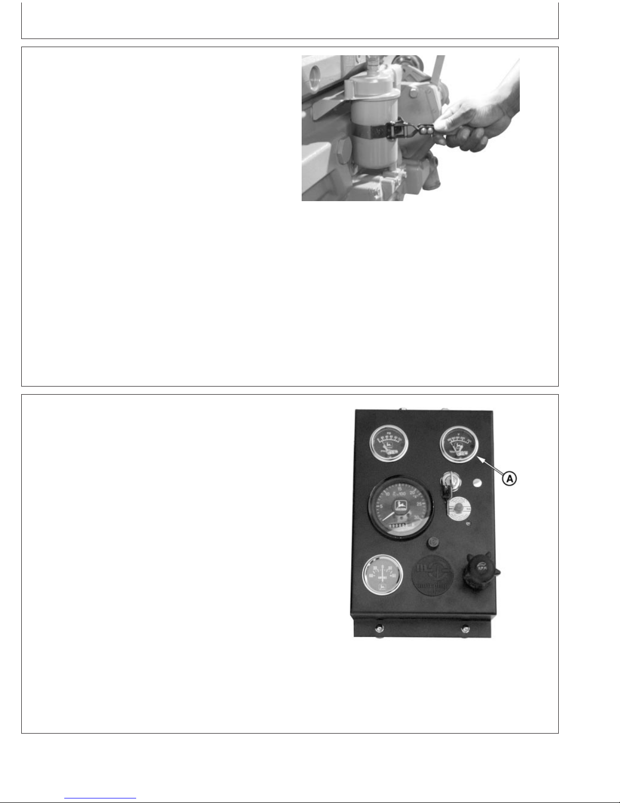
Engine Operating Guidelines
4. During the first 20 hours, avoid prolonged periods of
engine idling or sustained maximum load operation. If
engine will idle longer than 5 minutes, stop engine.
5. Before the first 250 hours (maximum), change engine
oil and replace engine oil filter. (See CHANGING
ENGINE OIL AND REPLACING OIL FILTER in
Lubrication and Maintenance/250 Hour/6 Month
Section.) Fill crankcase with the normal seasonal
viscosity grade oil. (See DIESEL ENGINE OIL, in
Fuels, Lubricants, and Coolant Section.)
NOTE: Some increase in oil consumption may be
expected when low viscosity oils are used. Check
oil levels more frequently.
If air temperature is below -10°C (14°F), use an
engine block heater.
Changing Oil And Oil Filter Before First 250 Hours
RG7961B –UN–22JAN99
6. Watch coolant temperature gauge (A) closely. If
coolant temperature rises above 112°C (234°F), reduce
load on engine. Unless temperature drops quickly, stop
the engine and determine the cause before resuming
operation.
NOTE: When the coolant temperature gauge reads
approximately 115°C (239°F), the engine will
shutdown automatically, if equipped with safety
controls.
7. Check poly-vee belt for proper alignment and seating
in pulley grooves.
A—Coolant Temperature Gauge
OURGP12,0000076 –19–09SEP04–3/4
RG11299F –UN–17AUG00
North American (1999— ) Instrument Panel Shown
15-8
OURGP12,0000076 –19–09SEP04–4/4
110306
PN=52
Page 53

Engine Operating Guidelines
Auxiliary Gear Drive Limitations
IMPORTANT: When attaching an air compressor,
hydraulic pump, or other accessory to
be driven by the auxiliary gear drive (A)
(engine timing gear train at front of
engine), power requirements of the
accessory must be limited to values
listed below:
• 30 kW (40 hp) Continuous Operation at 2500 rpm
• 37 kW (50 hp) Intermittent Operation at 2500 rpm
A—Auxiliary Gear Drive
Generator Set (Standby) Applications
To assure that your engine will deliver efficient standby
operation when needed, start engine and run at rated
speed (with 50%—70% load) for 30 minutes every 2
weeks. DO NOT allow engine to run extended period of
time with no load.
Auxiliary Gear Drive
RG7634A –UN–22JAN99
RG,RG34710,5555 –19–27JUL06–1/1
RG,RG34710,5556 –19–27JUL06–1/1
15-9
110306
PN=53
Page 54
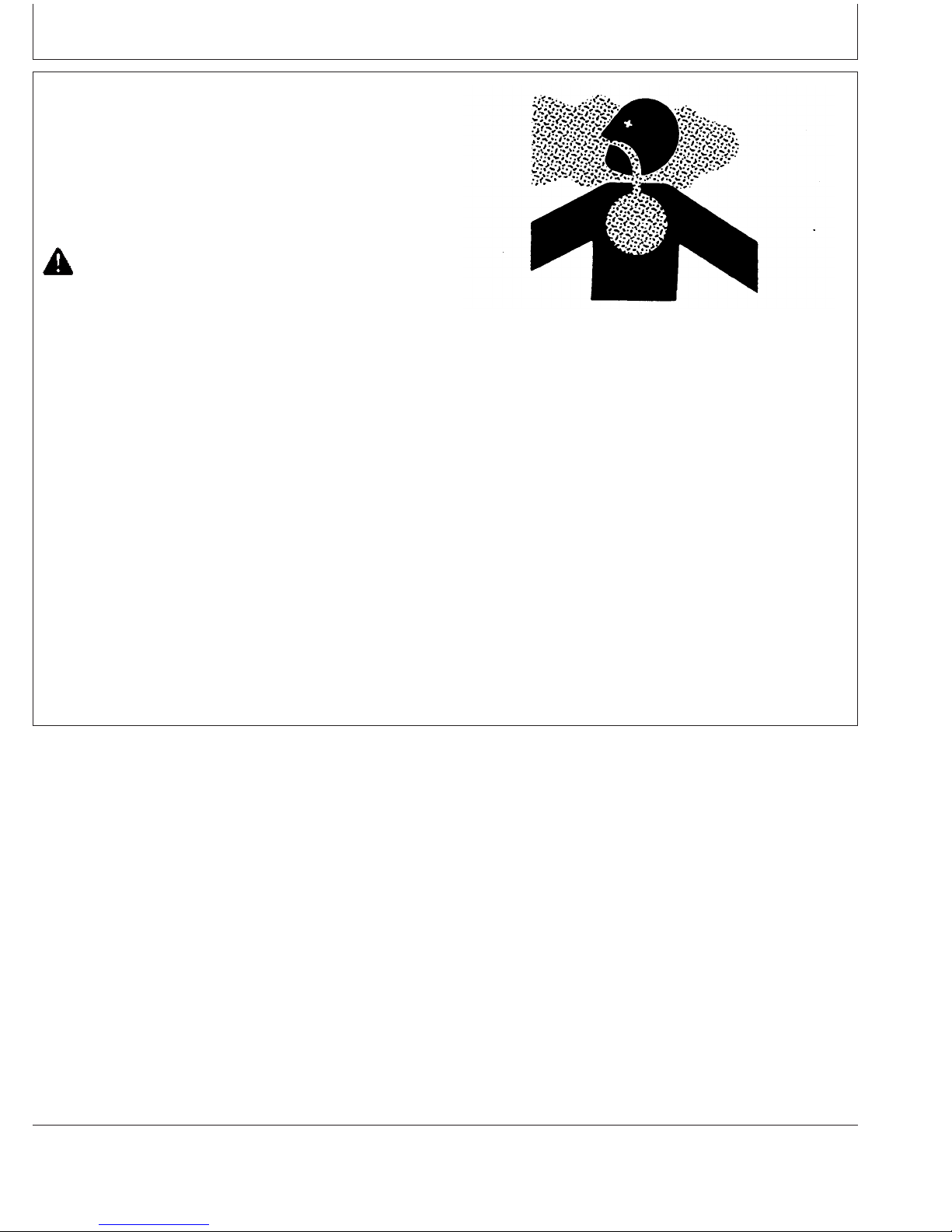
Engine Operating Guidelines
Starting the Engine
The following instructions apply to the optional controls
and instruments available through the John Deere Parts
Distribution Network. The controls and instruments for
your engine may be different from those shown here;
always follow manufacturer’s instructions.
CAUTION: Before starting engine in a confined
building, install proper outlet exhaust
ventilation equipment. Always use safety
approved fuel storage and piping.
NOTE: If temperature is below 0°C (32°F), it may be
necessary to use cold weather starting aids (See
COLD WEATHER OPERATION, later in this
section).
1. Perform all prestarting checks outlined in Lubrication &
Maintenance/Daily Section later in this manual.
Use Proper Ventilation
TS220 –UN–23AUG88
2. Open the fuel supply shut-off valve, if equipped.
3. Disengage clutch (if equipped) controlling any engine
drivelines.
Continued on next page
RG,RG34710,5557 –19–07JAN02–1/2
15-10
110306
PN=54
Page 55

Engine Operating Guidelines
NOTE: Electronically controlled governor applications may
be equipped with a rotary speed potentiometer on
the throttle (A) on the instrument panel.
4. On mechanical governor (7-10% regulation) engines,
pull hand throttle (A) 1/3 of the way out. Turn the handle
in either direction to lock it in place.
5. If equipped, depress and hold reset button (B) while
starting.
IMPORTANT: Do not operate the starter for more than
30 seconds at a time. To do so may
overheat the starter. If the engine does
not start the first time, wait at least 2
minutes before trying again. If engine
does not start after four attempts, see
Troubleshooting Section.
6. Turn the key switch (C) clockwise to crank the engine.
When the engine starts, release the key so that it returns
to the "ON" position.
North American Standard Instrument Panel (1999— ) Shown
RG11299X –UN–18OCT01
IMPORTANT: If the key switch is released before the
engine starts, wait until the starter and
the engine stop turning before trying
again. This will prevent possible
damage to the starter and/or flywheel.
7. After the engine starts, continue to hold the reset button
in until the oil pressure gauge (D) reads at least 105 kPa
(1.05 bar) (15 psi). The safety controls will not allow the
engine to run at a lower oil pressure unless the reset
button is held in.
IMPORTANT: Should the engine die when operating
under load, immediately disengage PTO
clutch and restart the engine.
Overheating of turbocharger parts may
occur when oil flow is stopped.
8. Check all gauges for normal engine operation. If
operation is not normal, stop the engine and determine
the cause.
VDO Standard Instrument Panel (Except North America)
RG11610 –UN–17OCT01
A—Hand Throttle
B—Reset Button
C—Key Start Switch
D—Oil Pressure Gauge
15-11
RG,RG34710,5557 –19–07JAN02–2/2
110306
PN=55
Page 56

Engine Operating Guidelines
Warming Engine
IMPORTANT: To assure proper lubrication, operate
engine at or below 1200 rpm with no
load for 1–2 minutes. Extend this period
2–4 minutes when operating at
temperatures below freezing.
Engines used in generator set
applications where the governor is
locked at a specified speed may not
have a slow idle function. Operate these
engines at high idle for 1 to 2 minutes
before applying the load. This
procedure does not apply to standby
generator sets where the engine is
loaded immediately upon reaching rated
speed.
1. Check oil pressure gauge (A) as soon as engine starts.
If gauge needle does not rise above minimum oil
pressure specification of 105 kPa (1.05 bar) (15.0 psi)
within 5 seconds, stop the engine and determine the
cause. Normal engine oil pressure is 345 kPa (3.45
bar) (50 psi) at rated full load speed (1800–2500 rpm)
with oil at normal operating temperature of 115°C
(240°F).
Standard North American Instrument Panel
RG11612 –UN–17OCT01
RG10613 –UN–21OCT99
Standard VDO Instrument Panel (Except North America)
NOTE: On certain engines, the oil pressure and coolant
temperature gauges are replaced by indicator
warning lights. The lights must be "OFF" when
engine is running.
2. Watch coolant temperature gauge (B). Do not place
engine under full load until it is properly warmed up.
The normal engine coolant temperature range is 82°—
94°C (180°—202°F).
NOTE: It is a good practice to operate the engine under a
lighter load and at lower speeds than normal for
the first few minutes after start-up.
A—Oil Pressure Gauge
B—Coolant Temperature Gauge
RG,RG34710,5560 –19–08JAN02–1/1
15-12
110306
PN=56
Page 57

Normal Engine Operation
Engine Operating Guidelines
Observe engine coolant temperature and engine oil
pressure. Temperatures and pressures will vary
between engines and with changing operating
conditions, temperatures, and loads.
Normal engine coolant operating temperature range is
82°—94°C (180°—202°F). If coolant temperature rises
above 112°C (234°F), reduce load on engine. Unless
temperature drops quickly, stop engine and determine
cause before resuming operation.
Operate the engine under a lighter load and at slower
than normal speed for first 15 minutes after start-up.
DO NOT run engine at slow idle.
IMPORTANT: Should the engine die while
operating under load, immediately
remove load and restart the engine.
Overheating of the turbocharger
parts may occur when oil flow is
stopped.
Stop engine immediately if there are any signs of part
failure. Symptoms that may be early signs of engine
problems are:
• Sudden drop in oil pressure
• Abnormal coolant temperatures
• Unusual noise or vibration
• Sudden loss of power
• Excessive black exhaust
• Excessive fuel consumption
• Excessive oil consumption
• Fluid leaks
RG,RG34710,5552 –19–20MAY96–1/1
15-13
110306
PN=57
Page 58
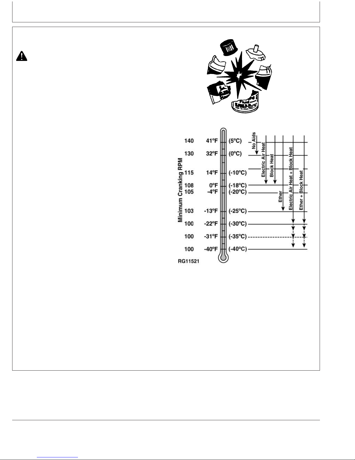
Cold Weather Operation
CAUTION: Ether injector starting fluid is highly
flammable. DO NOT use starting fluid on
engines equipped with air intake heaters.
DO NOT use starting fluid near fire, sparks, or
flames. DO NOT incinerate or puncture a
starting fluid container.
Engine Operating Guidelines
Engines may be equipped with intake air heaters, coolant
heaters, or ether injectors as a cold weather starting aid.
Starting aids are required below 32°F(0°C). They will
enhance starting performance above these temperatures
and may be needed to start applications that have high
parasitic loads during cranking and/or start acceleration to
idle.
Using correct grade of oil (per engine and machine
operator’s manual) is critical to achieving adequate cold
weather cranking speed.
Other cold weather starting aids are required at
temperatures below -22°F (-30°C) or at altitudes above
1500 m (5000 ft).
1. Follow steps 1—4 as listed under , then proceed as
follows according to the instrument (gauge) panel on
your engine.
2. Switch on the air intake heater for 30 seconds or
activate ether injector by following suppliers
instructions.
Handle Starting Fluid with Care
TS1356 –UN–18MAR92
RG11521 –19–10JAN01
Cold Weather Starting Guidelines
3. Follow remaining steps 5—8 as listed under earlier in
this section.
Additional information on cold weather operation is
available from your authorized servicing dealer.
15-14
RG,RG34710,5050 –19–08JAN02–1/1
110306
PN=58
Page 59
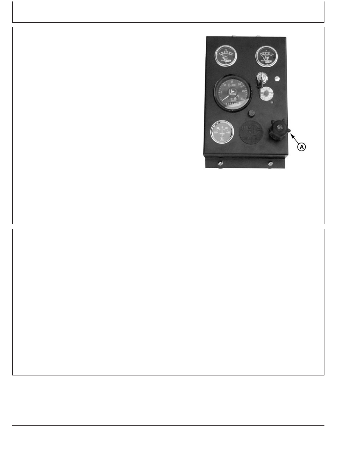
Engine Operating Guidelines
Changing Engine Speed
To increase engine speed, turn throttle handle (A), if
equipped, to the horizontal position and pull out until
desired engine speed is obtained. Turn the handle in
either direction to lock throttle position. The handle is
pushed inward to decrease engine speed.
NOTE: On engines without handle, use throttle lever to
control engine speed.
A—Throttle Handle
Avoid Excessive Engine Idling
Prolonged idling may cause the engine coolant
temperature to fall below its normal range. This, in
turn, causes crankcase oil dilution, due to incomplete
fuel combustion, and permits formation of gummy
deposits on valves, pistons, and piston rings. It also
promotes rapid accumulation of engine sludge and
unburned fuel in the exhaust system.
Once an engine is warmed to normal operating
temperatures, engine should be idled at slow idle
North American Standard Instrument Panel Shown
RG11299I –UN–11SEP00
RG,RG34710,5561 –19–07JAN02–1/1
speed. Slow idle speed for this engine is 850 rpm at
factory. If an engine will be idling for more than 5
minutes, stop and restart later.
NOTE: Generator set applications where the governor
is locked at a specified speed may not have a
slow idle function. These engines will idle at no
load governed speed (high idle).
15-15
RG,RG34710,5562 –19–27JUL06–1/1
110306
PN=59
Page 60

Engine Operating Guidelines
Stopping the Engine
1. Disengage clutch (if equipped) controlling engine
drivelines.
2. Move the throttle (A) to slow idle on standard
(mechanical) governor engines.
IMPORTANT: Before stopping an engine that has
been operating at working load, idle
engine at least 2 minutes at 1000–1200
rpm to cool hot engine parts.
For engines in generator set
applications, where the governor is
locked at a specified speed and no slow
idle function is available, run engine for
at least 2 minutes at fast idle and no
load.
3. Turn key switch (B) to "OFF" position to stop the
engine. Remove ignition key.
North American Standard Instrument Panel Shown
RG11299J –UN–11SEP00
IMPORTANT: Make sure that exhaust stack cap (rain
cap) is installed when engine is not
running. This will prevent water and dirt
from entering engine.
A—Throttle
B—Key Switch
Exhaust Stack Rain Cap
RG10616 –UN–16JUN00
RG,RG34710,5563 –19–07JAN02–1/1
15-16
110306
PN=60
Page 61

Engine Operating Guidelines
Using a Booster Battery or Charger
A 12-volt booster battery can be connected in parallel with
battery (ies) on the unit to aid in cold weather starting.
ALWAYS use heavy duty jumper cables.
CAUTION: Gas given off by battery is explosive.
Keep sparks and flames away from battery.
Before connecting or disconnecting a battery
charger, turn charger off. Make last connection
and first disconnection at a point away from
battery. Always connect NEGATIVE (–) cable
last and disconnect this cable first.
WARNING: Battery posts, terminals, and related
accessories contain lead and lead compounds, chemicals
known to the State of California to cause cancer and
reproductive harm. Wash hands after handling.
IMPORTANT: Be sure polarity is correct before
making connections. Reversed polarity
will damage electrical system. Always
connect positive to positive and
negative to ground. Always use 12-volt
booster battery for 12-volt electrical
systems and 24-volt booster battery
(ies) for 24-volt electrical systems.
Exploding Battery
TS204 –UN–23AUG88
RG4678 –UN–14DEC88
12-Volt System
1. Connect booster battery or batteries to produce the
required system voltage for your engine application.
NOTE: To avoid sparks, DO NOT allow the free ends of
jumper cables to touch the engine.
2. Connect one end of jumper cable to the POSITIVE (+)
post of the booster battery.
3. Connect the other end of the jumper cable to the
POSITIVE (+) post of battery connected to starter.
4. Connect one end of the other jumper cable to the
NEGATIVE (–) post of the booster battery.
5. ALWAYS complete the hookup by making the last
connection of the NEGATIVE (–) cable to a good
ground on the engine frame and away from the battery
(ies).
24-Volt System
RG4698 –UN–14DEC88
A—12-Volt Machine Battery (ies)
B—12-Volt Booster Battery (ies)
C—Booster Cable
D—Cable to Starting Motor
Continued on next page
15-17
RG,RG34710,5564 –19–27JUL06–1/2
110306
PN=61
Page 62

Engine Operating Guidelines
6. Start the engine. Disconnect jumper cables
immediately after engine starts. Disconnect NEGATIVE
(–) cable first.
RG,RG34710,5564 –19–27JUL06–2/2
15-18
110306
PN=62
Page 63
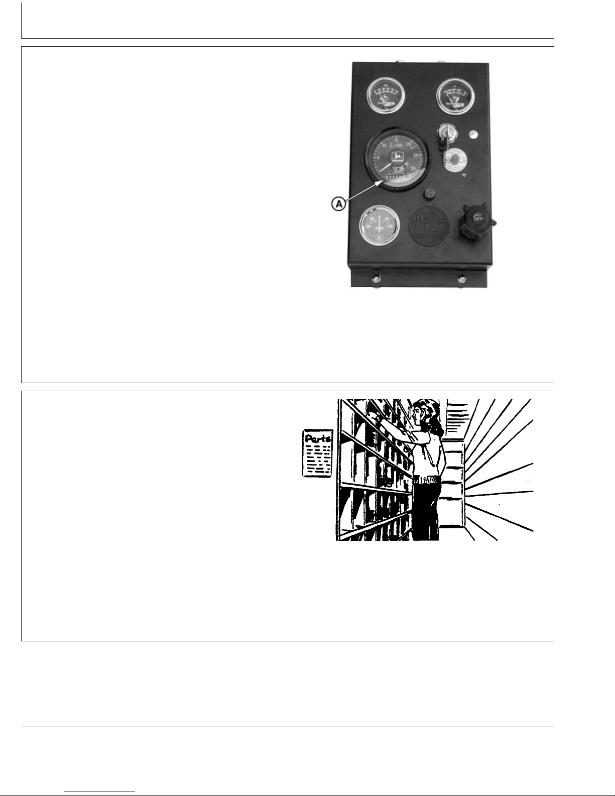
Lubrication and Maintenance
Observe Service Intervals
Using hour meter (A) as guide, perform all services at the
hourly intervals indicated on following pages. At each
scheduled maintenance interval, perform all previous
maintenance operations in addition to the ones specified.
Keep a record of hourly intervals and services performed
using charts provided in Lubrication and Maintenance
Records Section.
IMPORTANT: Recommended service intervals are for
normal operating conditions. Service
MORE OFTEN if engine is operated
under adverse conditions. Neglecting
maintenance can result in failures or
permanent damage to the engine.
A—Hour Meter
Use Correct Fuels, Lubricants, and Coolant
IMPORTANT: Use only fuels, lubricants, and coolants
meeting specifications outlined in
Fuels, Lubricants, and Coolant Section
when servicing your John Deere
Engine.
Consult your John Deere engine distributor, servicing
dealer or your nearest John Deere Parts Network for
recommended fuels, lubricants, and coolant. Also
available are necessary additives for use when operating
engines in tropical, arctic, or any other adverse conditions.
North American Instrument Panel Hour Meter Shown
RG11299A –UN–17AUG00
DPSG,OUOE003,20 –19–07JAN02–1/1
TS100 –UN–23AUG88
20-1
DPSG,OUOE003,20 –19–06JAN99–1/1
110306
PN=63
Page 64

Lubrication and Maintenance
Lubrication and Maintenance Service Interval
Chart—Standard Industrial Engines
NOTE: The service intervals below are for standard
industrial engines. See details in Sections which
follow these charts.
Lubrication and Maintenance Service Intervals
Item Daily 6 Month 12 Month 24 Month As Required
Check Engine Oil and Coolant Level •
Check Fuel Filter(s)/Water Separator Bowl •
Check Air Cleaner Dust Unloader Valve & Indicator
a
•
Perform Visual Walkaround Inspection •
Service Fire Extinguisher •
Change Engine Oil And Replace Oil Filter
b
Check Engine Mounts •
Service Battery •
Check Manual Belt Tensioner and Belt Wear •
Clean Crankcase Vent Tube •
Check Air Intake Hoses, Connections, & System •
Replace Single or Dual Fuel Filter Elements •
Check Automatic Belt Tensioner and Belt Wear •
Check Engine Speeds •
Check Engine Electrical Ground Connection •
Check Cooling System •
Coolant Solution Analysis-Add SCAs as required •
Pressure Test Cooling System •
Check Crankshaft Vibration Damper
Flush Cooling System
d
(6.8 L Engines)
c
Test Thermostats •
Check and Adjust Engine Valve Clearance •
Add Coolant •
Replace Air Cleaner Elements •
Replace Poly-Vee Belt •
Check Fuses •
a
Replace primary air cleaner element when restriction indicator shows a vacuum of 625 mm (25 in.) H2O.
b
Change the oil for the first time after 100 hours maximum of break-in operation. For subsequent oil and filter intervals, see recommendations
in section 10.
c
Replace crankshaft damper every 4500 hours or 60 months, whichever occurs first.
d
If John Deere COOL-GARD is used, the flushing interval may be extended to 3000 hours or 36 months. If John Deere COOL-GARD is used
and the coolant is tested annually AND additives are replenished as needed by adding a supplemental coolant additive, the flushing interval
may be extended to 5000 hours or 60 months, whichever occurs first.
250 Hour/ 500 Hour/ 2000 Hour/
•
•
•
Continued on next page
20-2
OURGP11,0000006 –19–13OCT06–1/2
110306
PN=64
Page 65

Lubrication and Maintenance
Lubrication and Maintenance Service Intervals
Item Daily 6 Month 12 Month 24 Month As Required
Check Air Compressor (If Equipped) •
Bleed Fuel System •
250 Hour/ 500 Hour/ 2000 Hour/
OURGP11,0000006 –19–13OCT06–2/2
20-3
110306
PN=65
Page 66
Lubrication and Maintenance
Lubrication and Maintenance Service Interval
Chart—Generator (Standby) Applications
NOTE: Use service intervals listed below for generator
(standby) applications. Match service items below
to titles in Lubrication and Maintenance Sections
for procedures.
Lubrication and Maintenance Service Intervals
Item Weeks 12 Months 12 Months or 24 Months As Required
Operate Engine at Rated Speed and 50%–70% Load a •
Minimum of 30 Minutes
Check Engine Oil and Coolant Level •
Check Fuel Filter(s)/Water Separator Bowl •
Check Air Cleaner Dust Unloader Valve & Indicator
a
Perform Visual Walkaround Inspection •
Service Fire Extinguisher •
Change Engine Oil and Replace Oil Filter
b
Check Engine Mounts •
Service Battery •
Clean Crankcase Vent Tube •
Check Air Intake Hoses, Connections, & System •
Replace Single or Dual Fuel Filter Elements •
Check Belt Tensioner and Belt Wear •
Check Engine Speeds •
Check Engine Electrical Ground Connection •
Check Cooling System •
Coolant Solution Analysis-Add SCAs as required •
Pressure Test Cooling System •
Check Variable Speed (Droop) (Gen-Sets) •
Check Crankshaft Vibration Damper
Flush Cooling System
d
(6.8 L Engines)
c
Test Thermostats •
Check and Adjust Engine Valve Clearance •
Add Coolant •
Replace Air Cleaner Elements •
a
Replace primary air cleaner element when restriction indicator shows a vacuum of 625 mm (25 in.) H2O.
b
Change the oil for the first time after 100 hours maximum of break-in operation. For subsequent oil and filter intervals, see recommendations
in section 10.
c
Replace crankshaft damper every 4500 hours or 60 months, whichever occurs first.
d
If John Deere COOL-GARD is used, the flushing interval may be extended to 3000 hours or 36 months. If John Deere COOL-GARD is used
and the coolant is tested annually AND additives are replenished as needed by adding a supplemental coolant additive, the flushing interval
may be extended to 5000 hours or 60 months, whichever occurs first.
Every 2 250 Hours or 500 Hours or 2000 Hours
•
•
•
•
Continued on next page
20-4
OURGP11,0000007 –19–31OCT06–1/2
110306
PN=66
Page 67

Lubrication and Maintenance
Lubrication and Maintenance Service Intervals
Item Weeks 12 Months 12 Months or 24 Months As Required
Replace Poly-Vee Belt •
Check Fuses •
Check Air Compressor (If Equipped) •
Bleed Fuel System •
Every 2 250 Hours or 500 Hours or 2000 Hours
OURGP11,0000007 –19–31OCT06–2/2
20-5
110306
PN=67
Page 68

Lubrication & Maintenance/Daily
Daily Prestarting Checks
Do the following BEFORE STARTING THE ENGINE for
the first time each day:
IMPORTANT: DO NOT add makeup oil until the oil
level is BELOW the add mark.
1. Check engine oil level on dipstick. Add as required,
using seasonal viscosity grade oil. (See DIESEL
ENGINE OIL in Fuels, Lubricants, and Coolant Section
for oil specifications.)
Depending on application, oil may be added at left (A)
or right (B) side oil filler cap and rocker arm cover filler
cap (C) locations.
IMPORTANT: DO NOT fill above the top mark on the
dipstick. Oil levels anywhere within
crosshatch (D) are considered in the
acceptable operating range.
Left Side Oil Filler Cap
RG8009A –UN–16JUN00
A—Left Side Oil Filler Cap
B—Right Side Oil Filler Cap
C—Cover Oil Filler Cap
D—Crosshatch On Dipstick
Right Side Oil Filler Cap
RG8028B –UN–15JAN99
Rocker Arm Cover Filler Cap
Crosshatch on Dipstick
RG8054A –UN–16JUN00
RG8025B –UN–16JUN00
Continued on next page
25-1
OURGP12,0000048 –19–13OCT06–1/4
110306
PN=68
Page 69

Lubrication & Maintenance/Daily
CAUTION: Explosive release of fluids from
pressurized cooling system can cause serious
burns.
Only remove filler cap when engine is cold or
when cool enough to touch with bare hands.
Slowly loosen cap to first stop to relieve
pressure before removing completely.
2. Check the coolant level when engine is cold. Coolant
level should be at bottom of filler neck. Fill radiator (A)
with proper coolant solution if level is low. (See
ADDING COOLANT in Service As Required Section.)
Check overall cooling system for leaks.
NOTE: Refer to your vehicle’s operator’s manual for
recommendations for non-John Deere supplied
accessories.
A—Fill Radiator
High-Pressure Fluids
TS281 –UN–23AUG88
Continued on next page
25-2
Fill Radiator
RG4675 –UN–14DEC88
OURGP12,0000048 –19–13OCT06–2/4
110306
PN=69
Page 70
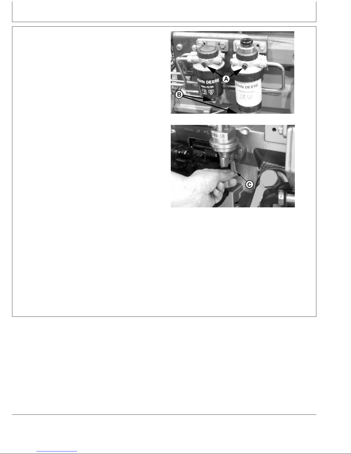
Lubrication & Maintenance/Daily
3. Check the single or dual fuel filters for water or debris.
If filter is fitted with a see-through water separator
bowl, drain as needed based on a daily visual
inspection.
IMPORTANT: Drain water into a suitable container
and dispose of properly.
a. Loosen drain plugs (B) at bottom of each fuel filter
or bowl, if equipped, two or three turns.
b. Loosen air bleed plugs (A) two full turns on fuel
filter mountings and drain water from bottom until
fuel starts to drain out.
c. When fuel starts to drain out, tighten drain plugs
securely.
After draining water from the fuel filter, the filter must
be primed by bleeding all air from the fuel system.
a. Operate primer lever of the fuel supply pump (C)
until fuel flow is free from air bubbles.
b. Tighten bleed plugs securely, and continue
operating hand primer until pumping action is not
felt. Primer lever is spring-loaded, and will return to
normal position.
If the fuel system needs further bleeding of air, see
BLEEDING FUEL SYSTEM in Service As Required
Section, later in this manual.
Drain Fuel Filters (Dual Filters Shown)
RG13542 –UN–20JUL04
RG7317A –UN–16JUN00
Priming At Fuel Supply Pump
A—Air Bleed Plugs
B—Drain Plugs
C—Fuel Supply Pump Primer Lever
Continued on next page
25-3
OURGP12,0000048 –19–13OCT06–3/4
110306
PN=70
Page 71

Lubrication & Maintenance/Daily
4. If the air cleaner has an automatic dust unloader valve
(A), squeeze the unloader valve on air cleaner
assembly to clear away any dust buildup.
If equipped with air intake restriction indicator gauge
(B), check gauge to determine if air cleaner needs to
be serviced.
IMPORTANT: Maximum air intake restriction is 6.25
kPa (0.06 bar) (1.0 psi) (25 in. H2O). A
clogged air cleaner element will cause
excessive intake restriction and a
reduced air supply to the engine.
Dust Unloader Valve and Indicator Gauge
RG7332A –UN–22JAN99
5. Make a thorough inspection of the engine
compartment. Look for oil or coolant leaks, worn fan
and accessory drive belts, loose connections and trash
build-up. Remove trash buildup and have repairs made
as needed if leaks are found.
NOTE: Wipe all fittings, caps, and plugs before
performing any maintenance to reduce the chance
of system contamination.
Inspect:
• Radiator for leaks and trash build-up.
• Air intake system hoses and connections for cracks
and loose clamps.
• Fan, alternator, and accessory drive belts for cracks,
breaks or other damage.
• Water pump for coolant leaks.
NOTE: It is normal for a small amount of leakage to occur
as the engine cools down and parts contract.
Excessive coolant leakage may indicate the need
to replace the water pump seal. Contact your
engine distributor or servicing dealer for repairs.
A—Dust Unloader Valve
B—Air Restriction Indicator
25-4
OURGP12,0000048 –19–13OCT06–4/4
110306
PN=71
Page 72

Lubrication & Maintenance/250 Hour/6 Month
Servicing Fire Extinguisher
A fire extinguisher (A) is available from your authorized
servicing dealer or engine distributor.
Read and follow the instructions which are packaged with
it. The extinguisher should be inspected at least every 250
hours of engine operation or once a month. Once
extinguisher is operated, no matter how long, it must be
recharged. Keep record of inspections on the tag which
comes with the extinguisher instruction booklet.
A—Fire Extinguisher
Fire Extinguisher
RG,RG34710,5567 –19–20MAY96–1/1
RW4918 –UN–15DEC88
30-1
110306
PN=72
Page 73

Lubrication & Maintenance/250 Hour/6 Month
Changing Engine Oil and Replacing Filter
NOTE: Change engine oil and oil filter for the first time
after 100 hours maximum of operation, then every
250 hours thereafter.
If John Deere PLUS-50or ACEA E4 or E5 engine oil and
a John Deere oil filter are used, the oil and filter change
interval may be extended by 50 percent.
OILSCANor OILSCAN PLUSis a John Deere sampling
program to help you monitor machine performance and
identify potential problems before they cause serious
damage. OILSCANand OILSCAN PLUSkits are
available from your John Deere engine distributor or
servicing dealer. Oil samples should be taken prior to the
oil change. Refer to instructions provided with kit.
To change engine oil and oil filter:
1. Run engine approximately 5 minutes to warm up oil.
Shut engine off.
2. Remove oil pan drain plug (arrow).
3. Drain crankcase oil from engine while warm.
NOTE: Drain plug location may vary, depending on the
application.
Oil Filter
RG11616 –UN–24OCT01
RG4881 –UN–29NOV88
Oil Pan Drain Plug
A—Oil Filter Element
PLUS-50 is a trademark of Deere & Company.
OILSCAN is a trademark of Deere & Company.
OILSCAN PLUS is a trademark of Deere & Company.
Continued on next page
30-2
OURGP12,0000078 –19–31OCT06–1/3
110306
PN=73
Page 74

Lubrication & Maintenance/250 Hour/6 Month
4. Turn filter element (A) counterclockwise using a
suitable filter wrench to remove. Discard oil filter
element.
NOTE: Depending on engine application, oil filter may be
located on either side of the engine.
5. Remove oil filter packing and clean filter mounting pad.
IMPORTANT: Filtration of oils is critical to proper
lubrication. Always change filter
regularly. Use filter meeting John Deere
performance specifications.
Removing Oil Filter Element
RG7961A –UN–22JAN99
6. Oil new packing and install new filter element. Hand
tighten element according to values printed on filter
element. If values are not provided, tighten element
approximately 3/4 — 1-1/4 turn after packing contacts
filter housing. DO NOT overtighten filter element.
7. Install oil pan drain plug with O-ring or copper washer.
If copper washer is used, install with raised center
against plug. If O-ring or washer is damaged, replace
it.
8. Tighten drain plug to specifications.
Specification
Oil Pan Drain Plug With Copper
Washer—Torque 70 N•m (52 lb ft).............................................................
Oil Pan Drain Plug With O-Ring—
Torque 50 N•m (37 lb ft).............................................................................
A—Oil Filter Element
Continued on next page
30-3
OURGP12,0000078 –19–31OCT06–2/3
110306
PN=74
Page 75

Lubrication & Maintenance/250 Hour/6 Month
9. Fill engine crankcase with correct John Deere engine
oil through rocker arm cover opening (B) or either side
oil filler (C) depending on engine application. (See
DIESEL ENGINE OIL in Fuels, Lubricants, and Coolant
Section for determining correct engine oil.)
To determine the correct oil fill quantity for your engine,
see ENGINE CRANKCASE OIL FILL QUANTITIES in
the Specifications Section of this manual.
IMPORTANT: Immediately after completing any oil
change, crank engine for 30 seconds
without permitting engine to start. This
will help insure adequate lubrication to
engine components before engine
starts.
NOTE: Crankcase oil capacity may vary slightly.
ALWAYS fill crankcase to full mark or within
crosshatch on dipstick, whichever is present. DO
NOT overfill.
Rocker Arm Cover Oil Filler
RG8025A –UN–19JUN00
10. Start engine and run to check for possible leaks.
11. Stop engine and check oil level after 10 minutes. Oil
level reading should be within crosshatch of dipstick.
Checking Engine Mounts
Engine mounting is the responsibility of the vehicle or
generator manufacturer. Follow manufacturer’s guidelines
for mounting specifications.
IMPORTANT: Use only Grade SAE 8 or higher grade
of hardware for engine mounting.
1. Check the engine mounting bracket, vibration isolators,
and mounting bolts on support frame and engine block
for tightness. Tighten as necessary.
Side Oil Filler
RG8054B –UN–19JUN00
B—Rocker Arm Cover Oil Filler
C—Side Oil Filler
OURGP12,0000078 –19–31OCT06–3/3
2. Inspect overall condition of vibration isolators, if
equipped. Replace isolators if rubber has deteriorated
or mounts have collapsed, as necessary.
30-4
DPSG,RG34710,111 –19–07JAN02–1/1
110306
PN=75
Page 76

Servicing Battery
CAUTION: Battery gas can explode. Keep
sparks and flames away from batteries. Use a
flashlight to check battery electrolyte level.
Never check battery charge by placing a metal
object across the posts. Use a voltmeter or
hydrometer.
Lubrication & Maintenance/250 Hour/6 Month
Always remove grounded NEGATIVE (–) battery
clamp first and replace it last.
WARNING: Battery posts, terminals, and related
accessories contain lead and lead compounds, chemicals
known to the State of California to cause cancer and
reproductive harm. Wash hands after handling.
1. On regular batteries, check electrolyte level. Fill each
cell to bottom of filler neck with distilled water.
NOTE: Low-maintenance or maintenance-free batteries
should require little additional service. However,
electrolyte level can be checked by cutting the
center section of decal on dash-line, and
removing cell plugs. If necessary, add clean, soft
water to bring level to bottom of filler neck.
2. Keep batteries clean by wiping them with a damp cloth.
Keep all connections clean and tight. Remove any
corrosion, and wash terminals with a solution of 1 part
baking soda and 4 parts water. Tighten all connections
securely.
NOTE: Coat battery terminals and connectors with a
mixture of petroleum jelly and baking soda to
retard corrosion.
Exploding Battery
TS204 –UN–23AUG88
3. Keep battery fully charged, especially during cold
weather. If a battery charger is used, turn charger off
before connecting charger to battery(ies). Attach
POSITIVE (+) battery charger lead to POSITIVE (+)
battery post. Then attach NEGATIVE (–) battery
charger lead to a good ground.
Continued on next page
30-5
RG,RG34710,5568 –19–27JUL06–1/2
110306
PN=76
Page 77
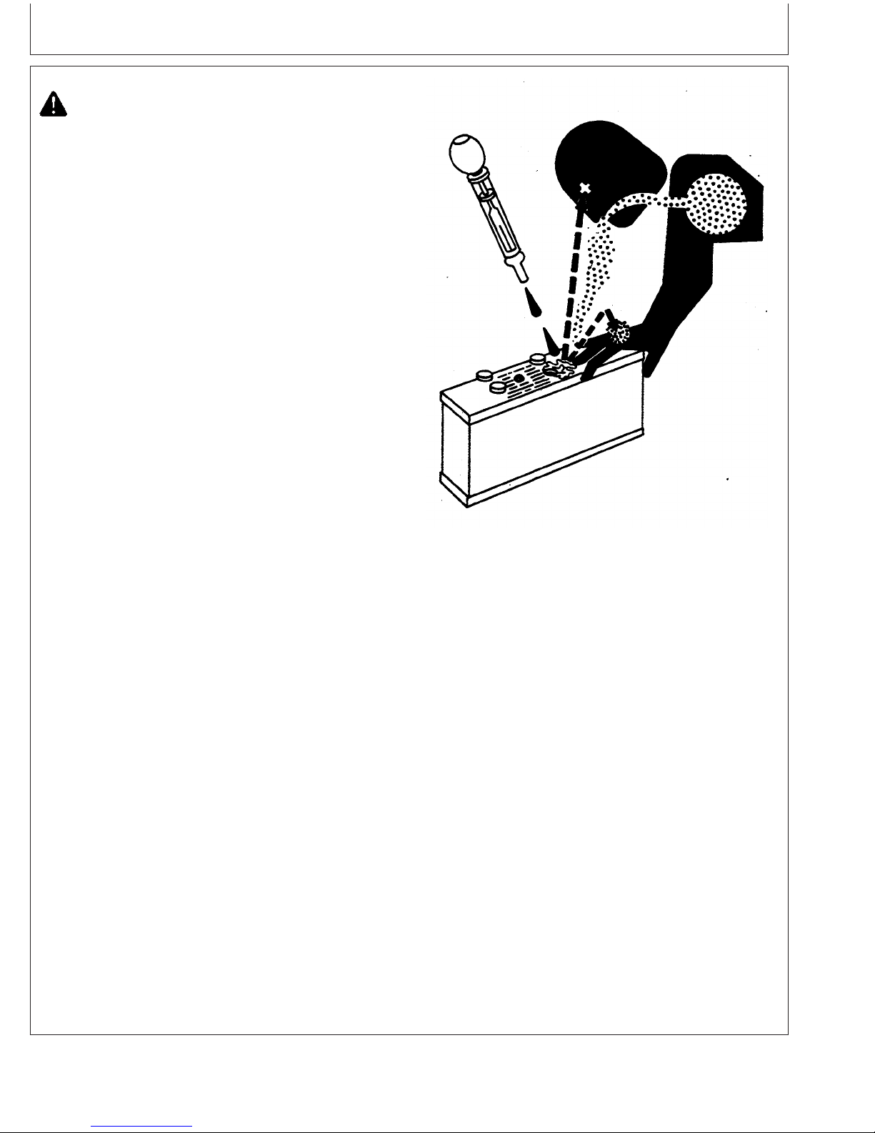
Lubrication & Maintenance/250 Hour/6 Month
CAUTION: Sulfuric acid in battery electrolyte is
poisonous. It is strong enough to burn skin, eat
holes in clothing, and cause blindness if
splashed into eyes.
Avoid the hazard by:
1. Filling batteries in a well-ventilated area.
2. Wearing eye protection and rubber gloves.
3. Avoiding breathing fumes when electrolyte is
added.
4. Avoiding spilling or dripping electrolyte.
5. Use proper jump start procedure.
If you spill acid on yourself:
1. Flush your skin with water.
2. Apply baking soda or lime to help neutralize
the acid.
3. Flush your eyes with water for 10–15
minutes. Get medical attention immediately.
If acid is swallowed:
1. Drink large amounts of water or milk.
2. Then drink milk of magnesia, beaten eggs, or
vegetable oil.
3. Get medical attention immediately.
In freezing weather, run engine at least 30 minutes to
assure thorough mixing after adding water to battery.
If necessary to replace battery(ies), replacements must
meet or exceed the following recommended capacities at
-18°C(0°F):
Specification
12 Volt Standard Duty Starter—
Cold Cranking Amps 640............................................................................
12 Volt Heavy Duty Starter—Cold
Cranking Amps 800.....................................................................................
24 Volt Standard Duty Starter—
Cold Cranking Amps 570............................................................................
Sulfuric Acid
TS203 –UN–23AUG88
30-6
RG,RG34710,5568 –19–27JUL06–2/2
110306
PN=77
Page 78
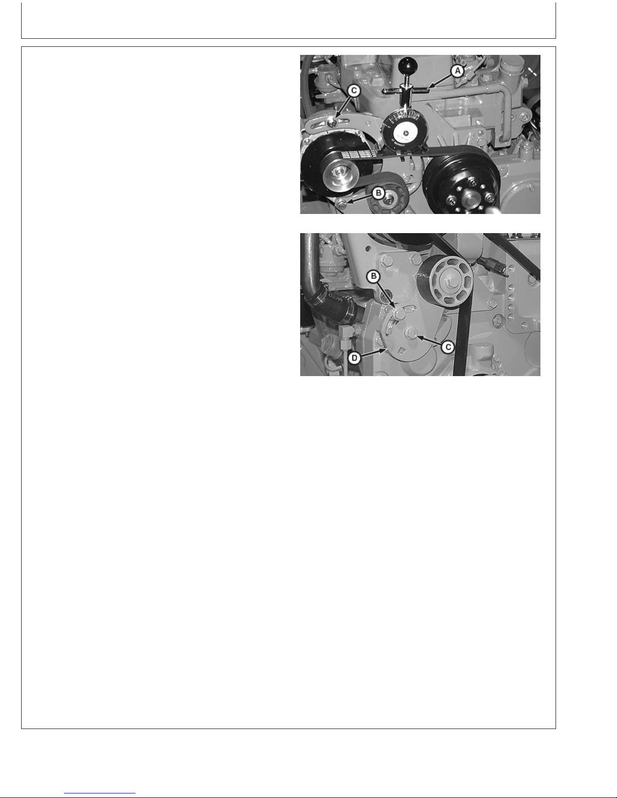
Lubrication & Maintenance/250 Hour/6 Month
Manual Belt Tensioner Adjustment
NOTE: Two types of manual tensioners shown.
NOTE: Inspect belts for cracks, fraying, or stretched-out
areas. Replace if necessary.
As a reference check, twist belt in the middle of a
254—305 mm (10—12 in.) span with two fingers.
A properly tensioned belt will turn 75—85
degrees. If belt turns more, it needs to be
tightened. If belt turns less, it needs to be
loosened.
NOTE: If timing gear cover or alternator bracket interfere
with installation/centering of belt tension gauge
(A), install gauge with face toward engine.
1. Install JDG1341 Belt Tension Gauge (A) on belt,
halfway between pulleys as shown. (JDG1341 Belt
Tension Gauge available from local John Deere Dealer
or Distributor.)
Check Belt Tension
RG10556 –UN–21DEC99
2. Loosen cap screws (B) and (C).
3. Slide alternator or tensioner bracket (D) in slot by hand
to remove all excess slack in belt.
IMPORTANT: Do not pry against alternator rear frame.
4. Stretch belt by prying outward on alternator front frame
or tensioner bracket. Observing tension gauge, stretch
the belt until specified tension is achieved.
Specification
New Belt—Tension 470—650 N (105—145 lb-force).................................
Used Belt—Tension 400—580 N (90—130 lb-force)..................................
5. Tighten cap screws (B) and (C).
NOTE: After ten minutes run-in, new belts are considered
used. Belt tension must then be rechecked per
used belt specifications.
6. Run engine for ten minutes and immediately re-check
belt tension per used belt specification above.
7. Reset belt tension as necessary.
Adjust Belt Tension
RG10557 –UN–21DEC99
A—Belt Tension Gauge
B—Cap Screw
C—Cap Screw
D—Tensioner Bracket
30-7
OURGP11,0000008 –19–24JUN04–1/1
110306
PN=78
Page 79
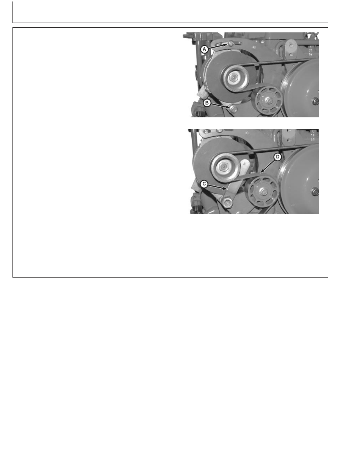
Lubrication & Maintenance/250 Hour/6 Month
Manual Belt Tensioner Adjustment Using
Belt Tension Tool (Alternate Method For
Engines Without Auxiliary Drive)
NOTE: The JDG1520 Belt Tension Tool may not be
compatible with all alternators. In that case, use
the preceding method for belt tensioning.
NOTE: Inspect belts for cracks, fraying, or stretched-out
areas. Replace if necessary.
As a reference check, twist belt in the middle of a
254—305 mm (10—12 in.) span with two fingers.
A properly tensioned belt will turn 75—85
degrees. If belt turns more, it needs to be
tightened. If belt turns less, it needs to be
loosened.
1. Loosen upper (A) and lower (B) alternator bracket cap
screws. Lower cap screw must remain tight enough to
prevent excessive alternator play but allow alternator to
pivot by hand.
2. Insert JDG1520 Belt Tension Tool (C) behind belt (D)
and over alternator mounting screw.
Alternator Bracket and Cap Screws
Belt Tension Tool
A—Upper Alternator Bracket Cap Screw
B—Lower Alternator Bracket Cap Screw
C—JDG1520 Belt Tension Tool
D—Belt
Continued on next page
RG11812 –UN–31OCT01
RG11813 –UN–31OCT01
OURGP11,0000009 –19–24JUN04–1/2
30-8
110306
PN=79
Page 80

Lubrication & Maintenance/250 Hour/6 Month
3. Place torque wrench (C) on belt tensioning tool (B) at
90° to tool. Pivot alternator (A) until desired torque is
achieved according to specification using the following
table.
New Belt—Tension 470—650 N (105—145 lb-force).................................
Specification
Used Belt—Tension 400—580 N (90—130 lb-force)..................................
JDG1520 Belt Tensioning Tool Torque Table
Desired Belt Tension Applied Torque On Tool
N (lb-force) N•m (lb-ft)
445 (100) 108 (90)
489 (110) 115 (85)
534 (120) 122 (90)
623 (140) 135 (100)
4. While holding tension with torque wrench (B), scribe a
reference mark (D) on alternator in line with notch (E)
on upper alternator bracket.
5. Continue to hold tension with torque wrench and
tighten upper alternator bracket cap screw.
6. Check position of reference mark to see if alternator
moved while tightening. If alternator moved, loosen
upper alternator bracket cap screw and repeat the
tension adjustment procedure.
Belt Tension Tool and Torque Wrench
RG11814 –UN–31OCT01
7. Remove belt tension tool and tighten lower alternator
bracket cap screw.
A—Alternator
B—Belt Tensioning Tool
C—Torque Wrench
D—Reference Mark
E—Alternator Upper Bracket Notch
Scribe Reference Mark
RG11815 –UN–31OCT01
OURGP11,0000009 –19–24JUN04–2/2
30-9
110306
PN=80
Page 81
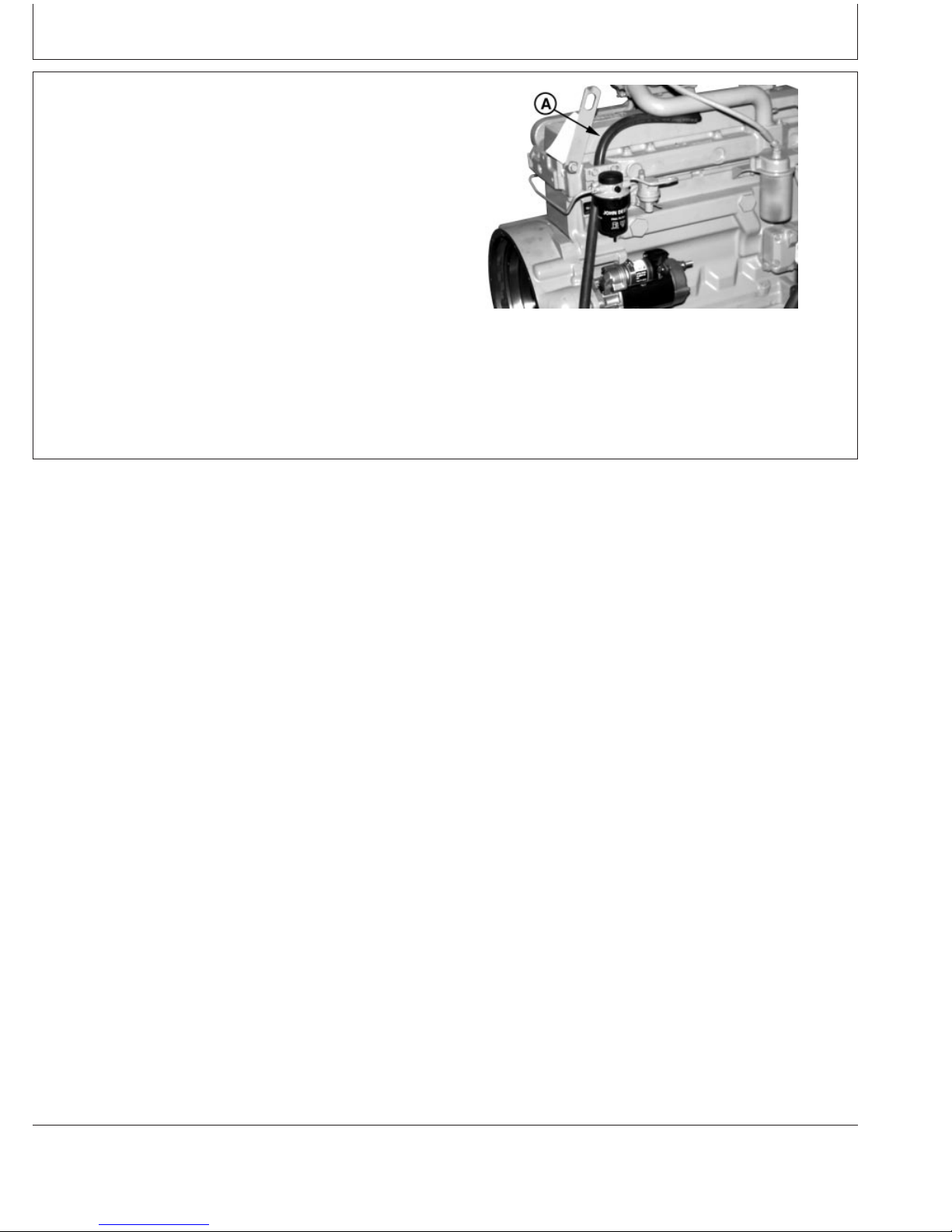
Lubrication & Maintenance/500 Hour/12 Month
Cleaning Crankcase Vent Tube
If you operate the engine in dusty conditions, clean the
tube at shorter intervals.
1. Remove and clean crankcase vent tube (A).
2. Install the vent tube. Be sure the O-ring fits correctly in
the rocker arm cover for elbow adapter. Tighten hose
clamp securely.
A—Crankcase Vent Tube
Crankcase Vent Tube
RG8017A –UN–19JUN00
RG,RG34710,5574 –19–08JAN02–1/1
35-1
110306
PN=81
Page 82

Lubrication & Maintenance/500 Hour/12 Month
Checking Air Intake System
IMPORTANT: The air intake system must not leak.
Any leak, no matter how small, may
result in internal engine damage due to
abrasive dirt and dust entering the
intake system.
1. Inspect all intake hoses (piping) for cracks. Replace as
necessary.
2. Check clamps (A) on piping which connect the air
cleaner, engine and, if present, turbocharger. Tighten
clamps as necessary. This will help prevent dirt from
entering the air intake system through loose
connections causing internal engine damage.
3. If engine has a rubber dust unloader valve (B), inspect
the valve on bottom of air cleaner for cracks or
plugging. Replace as necessary.
IMPORTANT: ALWAYS REPLACE primary air cleaner
element when air restriction indicator
shows a vacuum of 625 mm (25 in.)
H2O, is torn, or visibly dirty.
4. Test air restriction indicator (C) for proper operation.
Replace indicator as necessary.
IMPORTANT: If not equipped with air restriction
indicator, replace air cleaner elements
at 500 Hours or 12 Months, whichever
occurs first.
Check Clamps
RG4689 –UN–20DEC88
RG7332B –UN–22JAN99
Unloader Valve and Air Restriction Indicator
A—Clamps
B—Dust Unloader Valve
C—Air Restriction Indicator
35-2
RG,RG34710,5575 –19–07JAN02–1/1
110306
PN=82
Page 83

Lubrication & Maintenance/500 Hour/12 Month
Replacing Fuel Filter Element (Single Filter)
CAUTION: Escaping fluid under pressure can
penetrate the skin causing serious injury.
Relieve pressure before disconnecting fuel or
other lines. Tighten all connections before
applying pressure. Keep hands and body away
from pinholes and nozzles which eject fluids
under high pressure. Use a piece of cardboard
or paper to search for leaks. Do not use your
hand.
If any fluid is injected into the skin, it must be
surgically removed within a few hours by a
doctor familiar with this type injury or gangrene
may result. Doctors unfamiliar with this type of
injury may call the Deere & Company Medical
Department in Moline, Illinois, or other
knowledgeable medical source.
1. Close fuel shut-off valve, if equipped.
High-Pressure Fluids
X9811 –UN–23AUG88
2. Thoroughly clean fuel filter assembly and surrounding
area.
3. Loosen drain plug (C) and drain fuel into a suitable
container.
NOTE: Lifting up on retaining ring as it is rotated helps to
get it past raised locators.
4. Firmly grasp the retaining ring (A) and rotate it
clockwise 1/4 turn (when viewed from top). Remove
ring with filter element (B).
5. Inspect filter mounting base for cleanliness. Clean as
required.
NOTE: Raised locators on fuel filter canister must be
indexed properly with slots in mounting base for
correct installation.
6. Install new filter element onto mounting base. Be sure
element is properly indexed and firmly seated on base.
It may be necessary to rotate filter for correct
alignment.
Fuel Filter
RG7721 –UN–15JAN99
A—Retaining Ring
B—Filter Element
C—Drain Plug
D—Bleed Plug
Continued on next page
35-3
OURGP11,000000A –19–24JUN04–1/2
110306
PN=83
Page 84

Lubrication & Maintenance/500 Hour/12 Month
7. Align keys on filter element with slots in filter base.
8. Install retaining ring onto mounting base making certain
dust seal is in place on filter base. Hand tighten ring
(about 1/3 turn) until it “snaps” into the detent. DO
NOT overtighten retaining ring.
NOTE: The proper installation is indicated when a "click"
is heard and a release of the retaining ring is felt.
A plug is provided with the new element for
plugging the used element.
9. Open fuel shut-off valve and bleed the fuel system.
(See BLEEDING FUEL SYSTEM in Service As
Required Section.) Tighten bleed plug (D).
OURGP11,000000A –19–24JUN04–2/2
35-4
110306
PN=84
Page 85

Lubrication & Maintenance/500 Hour/12 Month
Replacing Fuel Filter Elements (Dual Filters)
CAUTION: Escaping fluid under pressure can
penetrate the skin causing serious injury.
Relieve pressure before disconnecting fuel or
other lines. Tighten all connections before
applying pressure. Keep hands and body away
from pinholes and nozzles which eject fluids
under high pressure. Use a piece of cardboard
or paper to search for leaks. Do not use your
hand.
If any fluid is injected into the skin, it must be
surgically removed within a few hours by a
doctor familiar with this type injury or gangrene
may result. Doctors unfamiliar with this type of
injury may call the Deere & Company Medical
Department in Moline, Illinois, or other
knowledgeable medical source.
1. Close fuel shut-off valve, if equipped.
High-Pressure Fluids
X9811 –UN–23AUG88
2. Thoroughly clean fuel filter assemblies and surrounding
area.
NOTE: Perform the following steps on each fuel filter.
3. Loosen drain plug (C) and drain fuel into a suitable
container.
NOTE: Lifting up on retaining ring as it is rotated helps to
get it past raised locators.
4. Firmly grasp the retaining ring (A) and rotate it
clockwise 1/4 turn (when viewed from top). Remove
ring with filter element (B).
5. Inspect filter mounting base for cleanliness. Clean as
required.
6. On primary filter with water separator, remove filter
element from water separator bowl. Drain and clean
separator bowl. Dry with compressed air. Install water
separator bowl onto new element. Tighten securely.
Dual Fuel Filters (Final Filter at Left, Primary Filter with Bowl at
RG13543 –UN–21JUL04
Right)
A—Retaining Ring
B—Filter Element
C—Drain Plug
D—Bleed Plug
Continued on next page
35-5
OURGP12,000004B –19–13OCT06–1/2
110306
PN=85
Page 86

Lubrication & Maintenance/500 Hour/12 Month
NOTE: Raised locators on fuel filter canister must be
indexed properly with slots in mounting base for
correct installation.
7. Install new filter element onto mounting base. Be sure
element is properly indexed and firmly seated on base.
It may be necessary to rotate filter for correct
alignment.
8. Align keys on filter element with slots in filter base.
9. Install retaining ring onto mounting base making certain
dust seal is in place on filter base. Hand tighten ring
(about 1/3 turn) until it “snaps” into the detent. DO
NOT overtighten retaining ring.
NOTE: The proper installation is indicated when a "click"
is heard and a release of the retaining ring is felt.
A plug is provided with the new element for
plugging the used element.
10. Open fuel shut-off valve and bleed the fuel system.
(See BLEEDING FUEL SYSTEM in Service As
Required Section.) Tighten bleed plug (D).
Checking Belt Tensioner Spring Tension and
Belt Wear (Automatic Tensioner)
Belt drive systems equipped with automatic (spring) belt
tensioners cannot be adjusted or repaired. The automatic
belt tensioner is designed to maintain proper belt tension
over the life of the belt. If tensioner spring tension is not
within specification, replace tensioner assembly.
OURGP12,000004B –19–13OCT06–2/2
Continued on next page
35-6
OURGP12,000004A –19–28JUL04–1/3
110306
PN=86
Page 87

Lubrication & Maintenance/500 Hour/12 Month
Checking Belt Wear
The belt tensioner is designed to operate within the limit
of arm movement provided by the cast stops (A and B)
when correct belt length and geometry is used.
Visually inspect cast stops (A and B) on belt tensioner
assembly.
If the tensioner stop on swing arm (A) is hitting the fixed
stop (B), check mounting brackets (alternator, belt
tensioner, idler pulley, etc.) and the belt length. Replace
belt as needed (see REPLACING FAN AND
ALTERNATOR BELTS in Service As Required Section).
Cast Stops
RG8098 –UN–18NOV97
A—Cast Stops
B—Cast Stop
Continued on next page
OURGP12,000004A –19–28JUL04–2/3
35-7
110306
PN=87
Page 88

Lubrication & Maintenance/500 Hour/12 Month
Checking Tensioner Spring Tension
A belt tension gauge will not give an accurate measure of
the belt tension when automatic spring tensioner is used.
Measure tensioner spring tension using a torque wrench
and procedure outlined below:
NOTE: Later engines have a 12.7 mm (1/2 in.) square
drive hole in tensioner, so no socket drive is
required.
1. Release tension on belt using a breaker bar and
socket (if required) on tension arm. Remove belt from
pulleys.
2. Release tension on tension arm and remove breaker
bar.
3. Put a mark (A) on swing arm of tensioner as shown.
4. Measure 21 mm (0.83 in.) from (A) and put a mark (B)
on tensioner mounting base.
5. Install torque wrench (C) so that it is aligned with
center of pulley and tensioner. Rotate the swing arm
with the torque wrench until marks (A and B) are
aligned.
6. Record torque wrench measurement and compare with
specification below. Replace tensioner assembly as
required.
Specification
Spring Tension—Torque 18-22 N•m (13-16 lb-ft).......................................
NOTE: Threads on earlier belt tensioner roller cap screw
are LEFT-HAND threads.
Marks on Tensioner
RG7977 –UN–14NOV97
RG12054 –UN–08JAN02
Align Marks
35-8
Align Torque Wrench With Pulley And Tensioner
RG12065 –UN–28JAN02
A—Mark On Swing Arm
B—Mark On Tensioner Mounting Base
C—Torque Wrench
OURGP12,000004A –19–28JUL04–3/3
110306
PN=88
Page 89

Lubrication & Maintenance/500 Hour/12 Month
Checking Engine Speeds
Observe tachometer (A) reading on the instrument panel
to verify engine speeds while running engine. (Refer to
Specifications section later in this manual for engine
speed specifications.) If engine speeds need adjustment,
contact your engine dealer or distributor.
A—Tachometer
Checking Engine Electrical Ground
Connections
Keep all engine ground connections clean and tight to
prevent electrical arcing which can damage electronic
components.
Check Engine Speed On Tachometer
RG11299A –UN–17AUG00
OURGP11,000000B –19–24JUN04–1/1
OUOD002,0000169 –19–08OCT01–1/1
35-9
110306
PN=89
Page 90

Checking Cooling System
CAUTION: Explosive release of fluids from
pressurized cooling system can cause serious
burns.
Shut off engine. Only remove filler cap when
cool enough to touch with bare hands. Slowly
loosen cap to first stop to relieve pressure
before removing completely.
Lubrication & Maintenance/500 Hour/12 Month
IMPORTANT: Air must be expelled from cooling
system when system is refilled. Loosen
temperature sending unit fitting at rear
of cylinder head or plug in thermostat
housing to allow air to escape when
filling system. Retighten fitting or plug
when all the air has been expelled.
1. Visually check entire cooling system for leaks. Tighten
all clamps securely.
2. Thoroughly inspect all cooling system hoses for hard,
flimsy, or cracked condition. Replace hoses if any of
the above conditions are found.
High-Pressure Fluids
TS281 –UN–23AUG88
RG,RG34710,5580 –19–20MAY96–1/1
35-10
110306
PN=90
Page 91
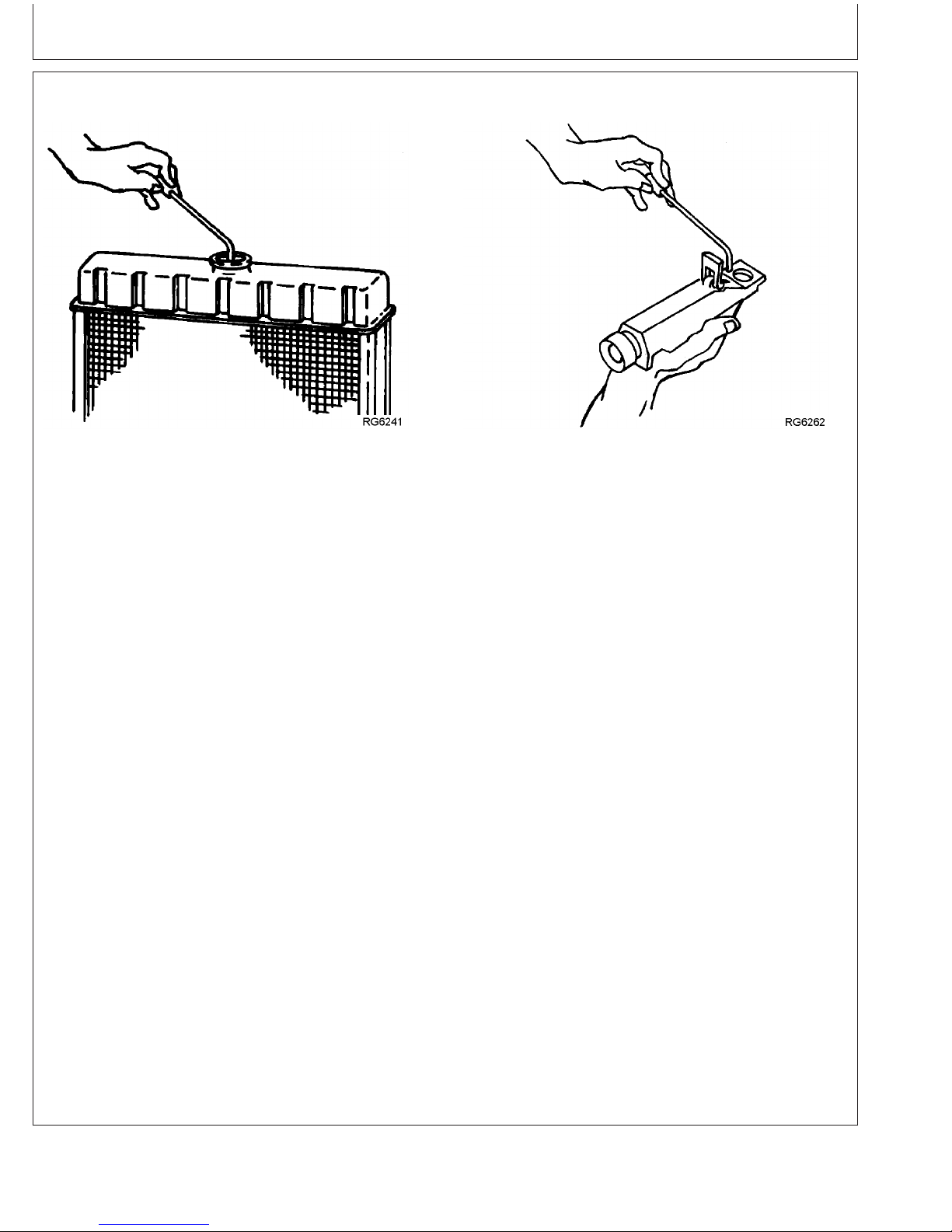
Lubrication & Maintenance/500 Hour/12 Month
Replenishing Supplemental Coolant Additives (SCAs) Between Coolant Changes
Radiator Coolant Check
IMPORTANT: Do not add supplemental coolant
additives when the cooling system is
drained and refilled with John Deere
COOL-GARD
NOTE: If system is to be filled with coolant that does
not contain SCAs, the coolant must be
precharged. Determine the total system
capacity and premix with 3% John Deere
Coolant Conditioner.
Through time and use, the concentration of coolant
additives is gradually depleted during engine operation.
Periodic replenishment of inhibitors is required, even
when John Deere COOL-GARDis used. The cooling
system must be recharged with additional
supplemental coolant additives available in the form of
liquid coolant conditioner.
Maintaining the correct coolant conditioner
concentration (SCAs) and freeze point is essential in
RG6261 –UN–08DEC97
JT07298 Coolant/Battery Tester
your cooling system to protect against rust, liner pitting
and corrosion, and freeze-ups due to incorrect coolant
dilution.
John Deere LIQUID COOLANT CONDITIONER is
recommended as a supplemental coolant additive
in John Deere engines.
DO NOT mix one brand of SCA with a different
brand.
Test the coolant solution every 500 hours or 12
months of operation using either John Deere coolant
test strips or a COOLSCANanalysis. If a
COOLSCANanalysis is not available, recharge the
system per instructions printed on label of John Deere
Liquid Coolant Conditioner.
RG6262 –UN–05DEC97
COOL-GARD is a registered trademark of Deere & Company
COOLSCAN is a registered trademark of Deere & Company
Continued on next page
35-11
DPSG,OUOD002,1921 –19–07JAN02–1/2
110306
PN=91
Page 92

Lubrication & Maintenance/500 Hour/12 Month
IMPORTANT: ALWAYS maintain coolant at correct
level and concentration. DO NOT
operate engine without coolant even
for a few minutes.
If frequent coolant makeup is
required, the glycol concentration
should be checked with JTO7298
Coolant/Battery Tester to ensure that
the desired freeze point is
maintained. Follow manufacturer’s
instructions provided with
Coolant/Battery Tester.
Add the manufacturer’s recommended concentration of
supplemental coolant additive. DO NOT add more than
the recommended amount.
The use of non-recommended supplemental coolant
additives may result in additive drop-out and gelation
of the coolant.
If other coolants are used, consult the coolant supplier
and follow the manufacturer’s recommendation for use
of supplemental coolant additives.
See DIESEL ENGINE COOLANTS AND
SUPPLEMENTAL ADDITIVE INFORMATION for
proper mixing of coolant ingredients before adding to
the cooling system.
Testing Diesel Engine Coolant
Testing Diesel Engine Coolant
Maintaining adequate concentrations of glycol and
inhibiting additives in the coolant is critical to protect
the engine and cooling system against freezing,
corrosion, and cylinder liner erosion and pitting.
Test the coolant solution at intervals of 12 months or
less and whenever excessive coolant is lost through
leaks or overheating.
Coolant test strips
Coolant test strips are available from your John Deere
dealer. These test strips provide a simple, effective
DPSG,OUOD002,1921 –19–07JAN02–2/2
method to check the freeze point and additive levels of
your engine coolant.
Compare the results to the supplemental coolant
additive (SCA) chart to determine the amount of
inhibiting additives in your coolant and whether more
John Deere COOLANT CONDITIONER should be
added.
COOLSCAN and COOLSCAN PLUS
For a more thorough evaluation of your coolant,
perform a COOLSCAN or COOLSCAN PLUS analysis,
where available. See your John Deere dealer for
information.
COOLSCAN is a trademark of Deere & Company
COOLSCAN PLUS is a trademark of Deere & Company
35-12
DX,COOL9 –19–19DEC03–1/1
110306
PN=92
Page 93
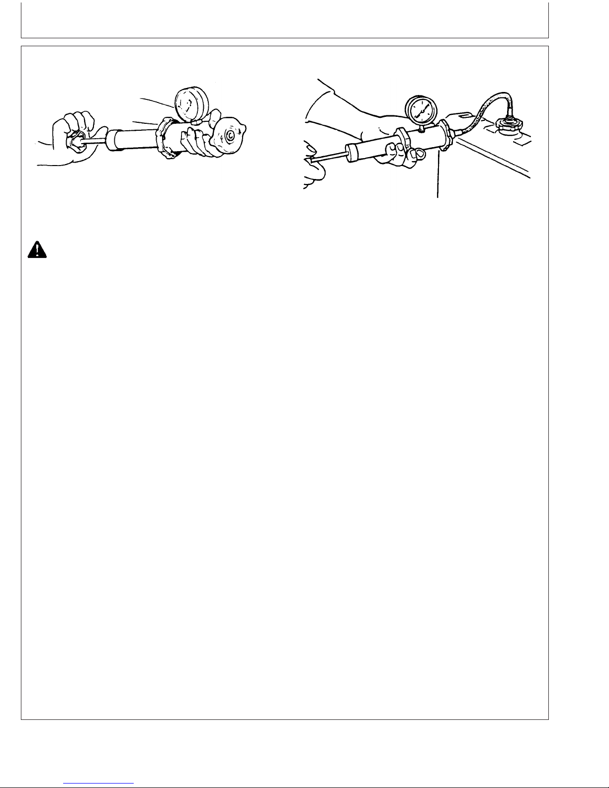
Lubrication & Maintenance/500 Hour/12 Month
Pressure Testing Cooling System
Test Radiator Cap
CAUTION: Explosive release of fluids from
pressurized cooling system can cause
serious burns.
Shut off engine. Only remove filler cap when
cool enough to touch with bare hands.
Slowly loosen cap to first stop to relieve
pressure before removing completely.
Test Radiator Cap
1. Remove radiator cap and attach to D05104ST
Tester as shown.
2. Pressurize cap to specification listed. Gauge should
hold pressure for 10 seconds within the normal
range if cap is acceptable.
If gauge does not hold pressure, replace radiator
cap.
RG6557 –UN–20JAN93
RG6558 –UN–20JAN93
Test Cooling System
1. Allow engine to cool, then carefully remove radiator
cap.
2. Fill radiator with coolant to the normal operating
level.
IMPORTANT: DO NOT apply excessive pressure to
cooling system, doing so may
damage radiator and hoses.
3. Connect gauge and adapter to radiator filler neck.
Pressurize cooling system to specification listed for
radiator cap.
4. With pressure applied, check all cooling system
hose connections, radiator, and overall engine for
leaks.
If leakage is detected, correct as necessary and
pressure test system again.
Radiator Cap Holding Pressure
(Not Opening For 10
Seconds)—Pressure 70 kPa (0.7 bar) (10 psi)
Specification
....................................
minimum
3. Remove the cap from gauge, turn it 180°, and
retest cap. This will verify that the first
measurement was accurate.
Test Cooling System
NOTE: Engine should be warmed up to test overall
cooling system.
35-13
If no leakage is detected, but the gauge indicated a
drop in pressure, coolant may be leaking internally
within the system or at the block-to-head gasket.
Have your engine distributor or servicing dealer
correct this problem immediately.
RG,RG34710,5586 –19–07JAN02–1/1
110306
PN=93
Page 94

Lubrication & Maint./2000 Hour/24 Month
Adjusting Variable Speed (Droop) on
Generator Set Engines
Stanadyne Mechanical Injection Pumps Only
1. Warm engine to normal operating temperature.
2. When necessary, disconnect throttle linkage or cable.
3. Adjust slow idle (C) and adjust fast idle (B) speed
when necessary.
4. Run engine at fast idle, then apply load until reaching
rated speed.
5. Check power. Adjust with the screw (A) if needed.
6. Remove load from engine.
7. Again check and adjust fast idle if screw (A) has been
turned.
8. Repeat procedure until both the engine power and the
fast idle speed are correct.
9. Reinstall throttle linkage if previously removed.
A—Adjustment Screw
B—Fast Idle Adjustment
C—Slow Idle Adjustment
Continued on next page
Droop Adjustment Screw
RG12066 –UN–29JAN02
RG,RG34710,5583 –19–28JAN02–1/3
40-1
110306
PN=94
Page 95

Lubrication & Maint./2000 Hour/24 Month
DENSO In-Line Injection Pumps Only
1. Check for specified no-load (frequency). If governor
regulation is within 5–7% range, no adjustment is
necessary.
2. If governor regulation is above 7% or below 5%, stop
engine and remove cap nuts from adjusting screws
before making adjustments.
3. Remove droop adjusting screw access plug (B, shown
removed) from top of governor housing.
4. Back out slow idle (adjusting) screw (D) and bumper
screw. Pull back on throttle lever (F, toward rear of
governor housing) by hand until the droop adjusting
screw (C) inside housing can be adjusted through the
access plug hole.
5. Screw the droop screw in (clockwise), counting the
turns until screw bottoms out. Then, return screw to
original setting.
NOTE: A noticeable click will occur at each 1/4 turn of
droop adjusting screw. One click clockwise will
increase no-load speed approximately 10 rpm,
counterclockwise will reduce speed by 10 rpm.
6. Screw in the droop screw (clockwise) no more than 1/2
turn (two clicks) at a time to reduce governor droop.
Turn counterclockwise no more than two clicks at a
time to increase governor droop (to reduce governor
sensitivity).
7. Replace access plug in top of governor housing. Start
engine, apply full (100%) load, and readjust high idle
adjusting screw until 1500 rpm is obtained at the
specified power.
8. Screw in idle (bumper) spring until engine speed
increases 5–10 rpm.
9. Repeat steps 4 through 7 until governor regulation is
within the 5–7% range.
10. Replace all cap nuts onto adjusting screws and
tighten lock nuts securely.
DENSO In-Line Injection Pump
RG5752 –UN–03NOV97
A—Fast Idle (Stop) Screw
B—Droop Adjusting Screw Access Plug Location
C—Droop Adjusting Screw
D—Slow Idle (Adjusting) Screw
E—Idle (Bumper) Spring
F—Throttle Lever
G—Mechanical Shutoff Lever
Continued on next page
40-2
RG,RG34710,5583 –19–28JAN02–2/3
110306
PN=95
Page 96
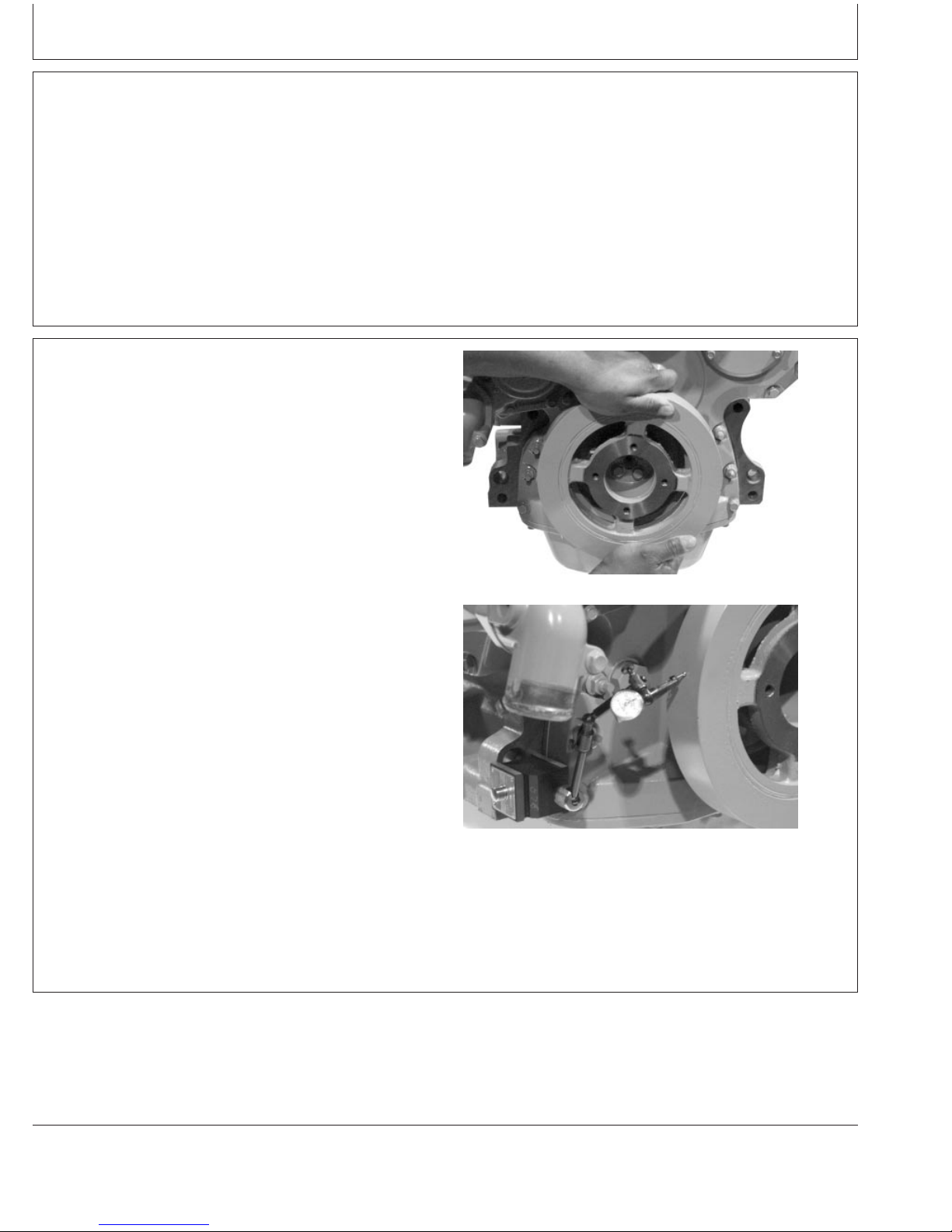
Lubrication & Maint./2000 Hour/24 Month
Delphi (Lucas) Injection Pumps Only
See your authorized Delphi (Lucas) Repair Station for
speed droop adjustment. This service requires that an
internal pump adjustment be made.
Checking Crankshaft Vibration Damper
(6-Cylinder Engine Only)
1. Remove belts (shown removed).
2. Grasp vibration damper with both hands and attempt to
turn it in both directions. If rotation is felt, damper is
defective and should be replaced.
RG,RG34710,5583 –19–28JAN02–3/3
IMPORTANT: The vibration damper assembly is not
repairable and should be replaced every
4500 hours or 60 months, whichever
occurs first.
3. Check vibration damper radial runout by positioning a
dial indicator (A) so probe contacts damper outer
diameter.
4. With engine at operating temperature, rotate crankshaft
using either JDE83 or JD81-1 Flywheel Turning Tool.
5. Note dial indicator reading. If runout exceeds
specifications given below, replace vibration damper.
Specification
Vibration Damper—Maximum
Radial Runout 1.50 mm (0.060 in.).............................................................
Grasp Vibration Damper
RG8018 –UN–15JAN99
RG7508 –UN–23NOV97
Check Runout
RG,RG34710,5585 –19–16JAN02–1/1
40-3
110306
PN=96
Page 97

Lubrication & Maint./2000 Hour/24 Month
Flushing and Refilling Cooling System
CAUTION: Explosive release of fluids from
pressurized cooling system can cause serious
burns.
Shut off engine. Only remove filler cap when
cool enough to touch with bare hands. Slowly
loosen cap to first stop to relieve pressure
before removing completely.
NOTE: When John Deere COOL-GARD is used, the drain
interval is 3000 hours or 36 months. The drain
interval may be extended to 5000 hours or 60
months of operation, provided that the coolant
is tested annually AND additives are
replenished, as needed, by adding a
supplemental coolant additive (SCA).
If COOL-GARD is not used, the flushing interval is
2000 hours or 24 months of operation.
Drain old coolant, flush the entire cooling system, test
thermostats, and fill with recommended clean coolant per
the following procedure.
1. Pressure test entire cooling system and pressure cap if
not previously done. (See PRESSURE TESTING
COOLING SYSTEM, in the Lubrication and
Maintenance/500 Hour/12 Month Section.)
2. Slowly open the engine cooling system filler cap or
radiator cap (A) to relieve pressure and allow coolant
to drain faster.
High-Pressure Fluids
TS281 –UN–23AUG88
RG12833 –UN–13FEB03
Radiator Cap
Continued on next page
40-4
OURGP11,000000C –19–24JUN04–1/3
110306
PN=97
Page 98

Lubrication & Maint./2000 Hour/24 Month
3. Open engine block drain valve (A) on left side of
engine. Drain all coolant from engine block.
NOTE: These engines use several different oil filter
adapters. Use either drain plug (B) or (C) to drain
coolant, whichever is more accessible for the oil
filter adapter on your engine.
4. Open radiator drain valve. Drain all coolant from
radiator.
5. Remove thermostats at this time, if not previously
done. Install cover (without thermostats) using old
gasket and tighten cap screws to 47 N•m (35 lb-ft).
6. Test thermostat opening temperature. (See Inspecting
Thermostats And Testing Opening Temperature in
Service As Required Section.)
7. Close all drain valves after coolant has drained.
CAUTION: Do not run engine longer than 10
minutes. Doing so may cause engine to
overheat which may cause burns when radiator
water is draining.
8. Fill the cooling system with clean water. Run the
engine about 10 minutes to stir up possible rust or
sediment.
9. Stop engine, pull off lower radiator hose and remove
radiator cap. Immediately drain the water from system
before rust and sediment settle.
10. After draining water, close drain valves. Reinstall
radiator cap and radiator hose and clamp. Fill the
cooling system with clean water and a heavy duty
cooling system cleaner such as Fleetguard
RESTORE and RESTORE PLUS. Follow
manufacturer’s directions on label.
Engine Block Drain Valve
RG8019A –UN–19JUN00
A—Engine Block Drain Valve
B—Engine Block Drain Plug
C—Engine Block Drain Plug
Fleetguard is a trademark of Cummins Engine Company, Inc.
RESTORE is a trademark of Fleetguard.
RESTORE PLUS is a trademark of Fleetguard.
Continued on next page
40-5
OURGP11,000000C –19–24JUN04–2/3
110306
PN=98
Page 99

Lubrication & Maint./2000 Hour/24 Month
11. After cleaning the cooling system, drain cleaner and
fill with water to flush the system. Run the engine
about 10 minutes, remove radiator cap and pull off
lower radiator hose to drain out flushing water.
12. Close all drain valves on engine and radiator.
Reinstall radiator hose and tighten clamps securely.
Install thermostats using a new gasket. (See
TESTING THERMOSTATS OPENING
TEMPERATURE later in this section.)
IMPORTANT: Air must be expelled from cooling
system when system is refilled. Loosen
temperature sending unit fitting at rear
of cylinder head or plug in thermostat
housing to allow air to escape when
filling system. Retighten fitting or plug
after filling cooling system.
NOTE: Coolant capacity may vary depending on
application.
13. Add coolant to radiator until coolant touches bottom of
filler neck. (See specification for capacity.) Install
radiator cap.
4.5 L Engine— Coolant Capacity 8.5 L (9 qt).............................................
6.8 L Engine—Coolant Capacity 11.3 L (12 qt)..........................................
Specification
14. Run engine until it reaches operating temperature.
This mixes the solution uniformly and circulates it
through the entire system. The normal engine coolant
temperature range is 82°—94°C (180° — 202°F).
15. After running engine, check coolant level and entire
cooling system for leaks.
16. Inspect the fan belt for wear and check belt tension.
(See Checking Belt Tensioner Spring Tension and
Belt Wear in Lubrication and Maintenance 500
Hour/12 Month section.
40-6
OURGP11,000000C –19–24JUN04–3/3
110306
PN=99
Page 100

Lubrication & Maint./2000 Hour/24 Month
Testing Thermostats Opening Temperature
To Remove Thermostat(s)
NOTE: On some engines, the coolant manifold/thermostat
housing is an integral part of the cylinder head.
CAUTION: Explosive release of fluids from
pressurized cooling system can cause serious
burns. DO NOT drain coolant until it has cooled
below operating temperature. Always loosen
radiator pressure cap or drain valve slowly to
relieve pressure.
1. Visually inspect area around thermostat housing for
leaks.
2. Remove radiator pressure cap and partially drain
cooling system.
3. Remove thermostat cover-to-water pump tube (A) and
seal.
High Pressure Fluids
TS281 –UN–23AUG88
A—Cover-To-Coolant Pump Tube
4. Remove thermostat cover (B) with gasket.
5. Remove thermostat(s)
6. Remove and discard all gasket material. Clean gasket
surfaces.
7. Clean and check cover for cracks or damage.
B—Thermostat Cover
Thermostat Cover-to-Water Pump Tube
RG8115A –UN–15JAN98
DPSG,RG34710,112 –19–07JAN02–1/5
RG7921A –UN–13NOV97
Thermostat Cover
Continued on next page
40-7
DPSG,RG34710,112 –19–07JAN02–2/5
110306
PN=100
 Loading...