

Page 1

P
OWERTECH
10.5 L & 12.5 L
Diesel Engines
Base Engine
TECHNICAL MANUAL
P
OWERTECH
Engines—Base Engine
10.5 L & 12.5 L Diesel
CTM100 06APR04 (ENGLISH)
For complete service information also see:
P
OWERTECH
Engines—Delphi/Lucas Electronic Fuel
Systems With Delphi/Lucas EUIs
.................................... CTM115
P
OWERTECH
Engines—Level 6 Electronic Fuel Systems
With Delphi/Lucas EUIs................. CTM188
OEM Engine Accessories ......CTM67 (English Only)
Alternators and Starter Motors........... CTM77
10.5 L & 12.5 L Diesel
10.5 L & 12.5 L Diesel
John Deere Power Systems
LITHO IN U.S.A.
Page 2

Forward
Introduction
This manual is written for an experienced technician.
Essential tools required in performing certain service
work are identified in this manual and are
recommended for use.
This manual (CTM100) covers only the base engine. It
is one of three volumes on 10.5 L and 12.5 L engines.
The following two companion manuals cover electronic
fuel system repair, operation and diagnostics:
• CTM115—Delphi/Lucas Electronic Fuel Systems
With Delphi/Lucas EUIs
• CTM188—Level 6 Electronic Fuel Systems With
Delphi/Lucas EUIs
CTM115 and CTM188 will cover fuel system repair,
formerly included in CTM100, Groups 35 and 36.
Other manuals will be added in the future to provide
added information on new electronic fuel systems.
A complete set of all three manuals covering the 10.5
L and 12.5 L engines can be procured by ordering
CTM650 Binder Set.
Live with safety: Read the safety messages in the
introduction of this manual and the cautions presented
throughout the text of the manual.
This is the safety-alert symbol. When you see this
symbol on the machine or in this manual, be alert to
the potential for personal injury.
Use this component technical manual in conjunction
with the machine technical manual. An application
listing in Section 01, Group 001 identifies
product-model/component type-model relationship.
Information is organized in sections and groups for the
various components requiring service instruction. At
the end of this manual are summary listings of all
applicable essential tools, service equipment and tools,
other materials needed to do the job, service parts kits,
specifications, wear tolerances, and torque values.
Before beginning repair on an engine, clean the engine
and mount on a repair stand. (See Section 2, Group
010.)
This manual contains SI Metric units of measure
followed immediately by the U.S. customary units of
measure. Most hardware on these engines is metric.
Some components of this engine may be serviced
without removing the engine from the machine. Refer
to the specific machine technical manual for
information on this and for engine removal and
installation procedures.
Read each block of material completely before
performing service to check for differences in
procedures or specifications. Follow only the
procedures that apply to the engine model number you
are working on. If only one procedure is given, that
procedure applies to all the engines in the manual.
CALIFORNIA PROPOSITION 65 WARNING
Diesel engine exhaust and some of its constituents
are known to the State of California to cause
cancer, birth defects and other reproductive harm.
CTM100 (06APR04) P
OWERTECH
RG,RG34710,1 –19–11OCT00–1/1
10.5 L & 12.5 L Diesel Engines
040604
PN=2
Page 3

John Deere Dealers
Introduction
The changes listed below make your CTM obsolete.
Repair, operation and diagnostics on 10.5 L and 12.5
L diesel engines is now covered in three manuals.
Fuel system repair has been removed from CTM100
and incorporated into its two companion manuals.
Discard CTM100 dated 20MAR01 and replace with
the following new manuals.
• CTM100—10.5 L and 12.5 L Diesel Engines—Base
Engine
• CTM115—10.5 L and 12.5 L Diesel Engines—
Delphi/Lucas Electronic Fuel Systems With
Delphi/Lucas EUIs
• CTM188—10.5 L and 12.5 L Diesel Engines—Level
6 Electronic Fuel Systems With Delphi/Lucas EUIs
Also, copy these pages listing changes and route
through your Service Department.
SECTION 01, GROUP 000 (Safety)
• Updated safety information.
SECTION 01, GROUP 001 (Engine Identification
and Applications)
• Revised procedure for adjusting valves and injector
preload.
• Revised procedure for repair of crankcase ventilation
assembly.
• Revised valve guide specifications.
• Revised procedure for installation of rocker arm
assembly.
SECTION 02, GROUP 030 (Cylinder Block, Liners,
Pistons and Rods)
• Revised procedure for connecting rod inspection.
SECTION 02, GROUP 040 (Crankshaft, Main
Bearings and Flywheel)
• Revised procedure for installing timing gear cover.
• Revised procedure for checking flywheel housing
face runout.
SECTION 02, GROUP 050 (Camshaft and Timing
Gear Train)
• Revised procedure for adjusting front timing gear
backlash.
• Updated engine model designation chart.
• Updated engine application charts.
SECTION 01, GROUP 002 (Fuels, Lubricants and
Coolants)
• Revised diesel/bio-diesel fuel guidelines and
specifications.
• Revised diesel engine oil guidelines.
• Revised oilscan and coolscan guidelines.
• Revised diesel engine coolant guidelines.
SECTION 02, GROUP 010 (Engine Rebuild)
• Added new engine front lift strap.
• Revised engine disassembly sequence.
• Revised engine assembly sequence.
SECTION 02, GROUP 020 (Cylinder Head and
Valves)
SECTION 02, GROUP 060 (Lubrication System)
• Added torque specifications for remote filter lines.
• Revised procedure for installation of oil pump.
• Revised specifications for oil pan cap screw torque.
SECTION 02, GROUP 070 (Cooling System)
• Revised procedure for replacement of fan drive
bearings.
• Revised procedure for replacement of belt
tensioners.
• Revised procedures for removal and installation of
thermostats.
SECTION 02, GROUP 080 (Air Intake and Exhaust
System)
• Added new information for extending turbocharger
life.
CTM100 (06APR04) P
OWERTECH
OUO1004,0000BBC –19–11OCT00–1/2
10.5 L & 12.5 L Diesel Engines
040604
PN=3
Page 4

Introduction
SECTION 02—GROUP 090 and 091(Fuel System)
NOTE: Repair procedures for fuel systems has been
moved to the following manuals:
• CTM115—Delphi/Lucas Electronic Fuel Systems
With Delphi/Lucas EUIs, Section 02, Group 090
• CTM188—Level 6 Electronic Fuel Systems With
Delphi/Lucas EUIs, Section 02, Group 090 (Dual
Rail System) and Group 091 (Single Rail System)
Later Tier II 12.5 L engines with dual- or single-rail fuel
systems are covered in CTM188.
SECTION 02—GROUP 100 (Starting and Charging
Systems)
• Updated torque specifications for alternator mounting
hardware.
SECTION 02—GROUP 110 (Electrical Engine
Control)
NOTE: Repair procedures for electrical engine control
components has been moved to section 02,
group 110 of the following manuals:
• CTM115—Delphi/Lucas Electronic Fuel Systems
With Delphi/Lucas EUIs
• CTM188—Level 6 Electronic Fuel Systems With
Delphi/Lucas EUIs
SECTION 03—GROUP 120 (Base Engine Operation)
• Base engine theory of operation is covered in this
section/group.
NOTE: Fuel system theory of operation has been
moved to Section 03, Group 130 of the
following manuals:
•
CTM115—Delphi/Lucas Electronic Fuel
Systems With Delphi/Lucas EUIs
•
CTM188—Level 6 Electronic Fuel Systems
With Delphi/Lucas EUIs
SECTION 04—GROUP 150 (Observable Diagnostics
and Tests)
• Base engine observable tests and diagnostics are
covered in this section/group.
NOTE: Fuel system testing and diagnostics has been
moved to Section 04, Group 150 in two other
technical manuals: CTM115—Delphi/Lucas
Electronic Fuel Systems With Delphi/Lucas
EUIs and CTM188—Level 6 Electronic Fuel
Systems With Delphi/Lucas EUIs.
SECTION 5 (Tools and Other Materials)
• All essential tools, service tools, dealer fabricated
tools and other materials listed throughout this
manual are consolidated in this section for ease of
reference.
SECTION 6 (Specifications)
• All repair, test and diagnostic specifications listed
throughout this manual are consolidated in this
section for ease of reference.
• Updated dynamometer test specifications.
• Updated intake manifold pressure specifications.
CTM100 (06APR04) P
OWERTECH
OUO1004,0000BBC –19–11OCT00–2/2
10.5 L & 12.5 L Diesel Engines
040604
PN=4
Page 5

POWERTECH6105HF and 6125HF Engines
Introduction
Right Side View (Early Engine)
3/4 Right Front View (Early Engine)
RG9030 –UN–21MAY98
RG9032 –UN–21MAY98
Left Side View (Early Engine)
RG9031 –UN–21MAY98
RG9033 –UN–21MAY98
3/4 Left Front View (Early Engine)
P
OWERTECH
is a registered trademark of Deere & Company.
CTM100 (06APR04) P
OWERTECH
RG,RG34710,3 –19–06NOV00–1/1
10.5 L & 12.5 L Diesel Engines
040604
PN=5
Page 6

Introduction
POWERTECH6105HF and 6125HF Engines—Continued
3/4 Right Rear View (Early Engine)
Right Side View Later Engine S.N. (30000— )
RG11174 –UN–20NOV00
RG11171A –UN–03NOV00
3/4 Left Rear View (Early Engine)
RG11175 –UN–20NOV00
RG11172A –UN–04DEC00
3/4 Right Front View Later Engine S.N. (30000— )
P
OWERTECH
is a registered trademark of Deere & Company.
CTM100 (06APR04) P
OWERTECH
DPSG,OUO1004,915 –19–16NOV00–1/1
10.5 L & 12.5 L Diesel Engines
040604
PN=6
Page 7

Introduction
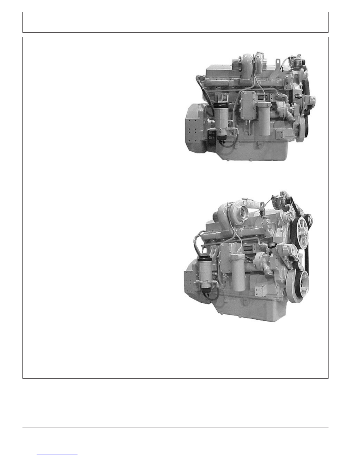
POWERTECH6105HRW and 6125HRW Engines
Right Side View
3/4 Right Front View
RG8222 –UN–21MAY98
RG8223 –UN–21MAY98
Left Side View
RG8221 –UN–21MAY98
RG8224 –UN–21MAY98
3/4 Left Front View
P
OWERTECH
is a registered trademark of Deere & Company.
CTM100 (06APR04) P
OWERTECH
RG,RG34710,3A –19–30SEP97–1/1
10.5 L & 12.5 L Diesel Engines
040604
PN=7
Page 8

Introduction
POWERTECH6105HRW and 6125HRW Engines—Continued
P
OWERTECH
3/4 Right Rear View
RG8220 –UN–21MAY98
is a registered trademark of Deere & Company.
3/4 Left Rear View
RG8219 –UN–21MAY98
DPSG,OUO1004,916 –19–30JUN99–1/1
CTM100 (06APR04) P
OWERTECH
10.5 L & 12.5 L Diesel Engines
040604
PN=8
Page 9

POWERTECH6105ADW Engine
Introduction
Right Side View (Early Engine)
3/4 Right Rear View (Early Engine)
RG8454 –UN–21MAY98
RG8453 –UN–21MAY98
3/4 Left Front View (Early Engine)
RG8448 –UN–21MAY98
RG8451 –UN–21MAY98
3/4 Left Rear View (Early Engine)
P
OWERTECH
is a registered trademark of Deere & Company.
CTM100 (06APR04) P
OWERTECH
RG,RG34710,5 –19–30SEP97–1/1
10.5 L & 12.5 L Diesel Engines
040604
PN=9
Page 10

Introduction
POWERTECH6105ADW Engine—Continued
P
OWERTECH
Right Side View Later Engines S.N. (30000—)
is a registered trademark of Deere & Company.
RG11171A –UN–03NOV00
Right Front View Later Engines S.N. (30000—)
RG11172A –UN–04DEC00
OUO1080,000028D –19–27AUG02–1/1
CTM100 (06APR04) P
OWERTECH
10.5 L & 12.5 L Diesel Engines
040604
PN=10
Page 11
POWERTECH6125 Tier II (30000—)
Introduction
Right Side View (30000—)
Right Front View (30000—)
RG11171A –UN–03NOV00
RG11172A –UN–04DEC00
P
OWERTECH
is a registered trademark of Deere & Company.
CTM100 (06APR04) P
OWERTECH
RE38635,0000026 –19–20JUN03–1/1
10.5 L & 12.5 L Diesel Engines
040604
PN=11
Page 12

6105 and 6125 Engine Cutaway View
Introduction
Engine Cutaway View
A—Oil Cooler E—Crankshaft I—Piston Rings M—Valves
B—Oil Pump Drive Gear F—Cylinder Liner J—Connecting Rod N—Electronic Unit Injector
C—Idler Gear G—Cylinder Liner O-Rings K—Oil Spray Jet O—Two-Piece Rocker Arm
D—Camshaft Gear H—Piston L—Camshaft Shaft
RG,RG34710,8 –19–30SEP97–1/1
CTM100 (06APR04) P
OWERTECH
10.5 L & 12.5 L Diesel Engines
RG8435 –UN–12JUL99
040604
PN=12
Page 13

SECTION 01—General Information
Group 000—Safety
Group 001—Engine Identification and Applications
Group 002—Fuels, Lubricants and Coolant
Contents
01
SECTION 02—Repair and Adjustments
Group 010—Engine Rebuild Guide, Break-In and
Tune-Up
Group 020—Cylinder Head and Valves
Group 030—Cylinder Block, Liners, Pistons, and
Rods
Group 040—Crankshaft, Main Bearings, and
Flywheel
Group 050—Camshaft and Timing Gear Train
Group 060—Lubrication System
Group 070—Cooling System
Group 080—Air Intake and Exhaust System
Group 090—Fuel System
Group 100—Starting and Charging Systems
SECTION 03—Theory of Operation
Group 120—Base Engine Operation
SECTION 04—Diagnostics
Group 150—Observable Diagnostics and Tests
SECTION 05—Tools and Other Materials
Group 170—Repair Tools and Other Materials
Group 180—Diagnostic Service Tools
Group 190—Dealer Fabricated Service Tools
02
03
04
05
06
SECTION 06—Specifications
Group 200—Repair and General OEM
Specifications
Group 210—Diagnostic Specifications
All information, illustrations and specifications in this manual are based on
the latest information available at the time of publication. The right is
reserved to make changes at any time without notice.
COPYRIGHT2003
DEERE & COMPANY
Moline, Illinois
A John Deere ILLUSTRUCTIONManual
All rights reserved
Previous Editions
Copyright1996, 1997, 1999, 2001
INDX
CTM100 (06APR04)
i
P
OWERTECH
10.5 L & 12.5 L Diesel Engines
040604
PN=1
Page 14

01
02
03
04
05
Contents
06
INDX
CTM100 (06APR04)
ii
P
OWERTECH
10.5 L & 12.5 L Diesel Engines
040604
PN=2
Page 15

Page
Group 000—Safety ....................01-000-1
Group 001—Engine Identification and Applications
Engine Model Designation................01-001-1
Engine Serial Number Plate Information .....01-001-2
Engine Option Code Label ...............01-001-3
Engine Application Chart.................01-001-4
Group 002—Fuels, Lubricants and Coolant
Diesel Fuel ...........................01-002-1
Bio-Diesel Fuel ........................01-002-2
Lubricity of Diesel Fuel ..................01-002-3
Dieselscan Fuel Analysis.................01-002-3
Diesel Engine Break-In Oil ...............01-002-4
Diesel Engine Oil—Non-Certified and Tier I
Certified Engines .....................01-002-5
Diesel Engine Oil—Tier II Engines .........01-002-6
Extended Diesel Engine Oil Service
Intervals............................01-002-7
Alternative and Synthetic Lubricants ........01-002-7
Mixing of Lubricants ....................01-002-8
OILSCANand COOLSCAN ............01-002-8
Grease ..............................01-002-9
Diesel Engine Coolant..................01-002-10
Supplemental Coolant Additives ..........01-002-11
Testing Diesel Engine Coolant ...........01-002-12
Replenishing Supplemental Coolant
Additives (SCAs) Between Coolant
Changes ..........................01-002-13
Operating in Warm Temperature Climates . .01-002-14
Flush and Service Cooling System ........01-002-15
Disposing of Coolant...................01-002-16
01
Section 01
General Information
Contents
CTM100 (06APR04)
01-1
P
OWERTECH
10.5 L & 12.5 L Diesel Engines
040604
PN=1
Page 16

01
Contents
CTM100 (06APR04)
01-2
P
OWERTECH
10.5 L & 12.5 L Diesel Engines
040604
PN=2
Page 17

Handle Fluids Safely—Avoid Fires
When you work around fuel, do not smoke or work near
heaters or other fire hazards.
Store flammable fluids away from fire hazards. Do not
incinerate or puncture pressurized containers.
Make sure machine is clean of trash, grease, and debris.
Do not store oily rags; they can ignite and burn
spontaneously.
Group 000
Safety
01
000
1
TS227 –UN–23AUG88
DX,FLAME –19–29SEP98–1/1
Service Cooling System Safely
Explosive release of fluids from pressurized cooling
system can cause serious burns.
Shut off engine. Only remove filler cap when cool enough
to touch with bare hands. Slowly loosen cap to first stop
to relieve pressure before removing completely.
Prepare for Emergencies
Be prepared if a fire starts.
Keep a first aid kit and fire extinguisher handy.
Keep emergency numbers for doctors, ambulance service,
hospital, and fire department near your telephone.
DX,RCAP –19–04JUN90–1/1
TS281 –UN–23AUG88
CTM100 (06APR04)
01-000-1
P
OWERTECH
DX,FIRE2 –19–03MAR93–1/1
10.5 L & 12.5 L Diesel Engines
TS291 –UN–23AUG88
040604
PN=17
Page 18

01
000
Handling Batteries Safely
2
CAUTION: Battery gas can explode. Keep
sparks and flames away from batteries. Use a
flashlight to check battery electrolyte level.
Never check battery charge by placing a metal
object across the posts. Use a voltmeter or
hydrometer.
Safety
Always remove grounded (-) battery clamp first
and replace it last.
CAUTION: Sulfuric acid in battery electrolyte is
poisonous. It is strong enough to burn skin, eat
holes in clothing, and cause blindness if
splashed into eyes.
Avoid the hazard by:
1. Filling batteries in a well-ventilated area.
2. Wearing eye protection and rubber gloves.
3. Avoiding breathing fumes when electrolyte is
added.
4. Avoiding spilling or dripping electrolyte.
5. Use proper jump start procedure.
If you spill acid on yourself:
1. Flush your skin with water.
2. Apply baking soda or lime to help neutralize
the acid.
3. Flush your eyes with water for 15—30
minutes. Get medical attention immediately.
Explosion
TS204 –UN–23AUG88
If acid is swallowed:
1. Do not induce vomiting.
2. Drink large amounts of water or milk, but do
not exceed2L(2quarts).
3. Get medical attention immediately.
WARNING: Battery posts, terminals, and related
accessories contain lead and lead compounds, chemicals
known to the State of California to cause cancer and
reproductive harm. Wash hands after handling.
CTM100 (06APR04)
01-000-2
P
OWERTECH
Acid
DPSG,OUO1004,2758 –19–11MAY00–1/1
10.5 L & 12.5 L Diesel Engines
040604
PN=18
TS203 –UN–23AUG88
Page 19

Safety
Avoid High-Pressure Fluids
Escaping fluid under pressure can penetrate the skin
causing serious injury.
Avoid the hazard by relieving pressure before
disconnecting hydraulic or other lines. Tighten all
connections before applying pressure.
Search for leaks with a piece of cardboard. Protect hands
and body from high pressure fluids.
If an accident occurs, see a doctor immediately. Any fluid
injected into the skin must be surgically removed within a
few hours or gangrene may result. Doctors unfamiliar with
this type of injury should reference a knowledgeable
medical source. Such information is available from Deere
& Company Medical Department in Moline, Illinois, U.S.A.
01
000
3
X9811 –UN–23AUG88
Wear Protective Clothing
Wear close fitting clothing and safety equipment
appropriate to the job.
Prolonged exposure to loud noise can cause impairment
or loss of hearing.
Wear a suitable hearing protective device such as
earmuffs or earplugs to protect against objectionable or
uncomfortable loud noises.
Operating equipment safely requires the full attention of
the operator. Do not wear radio or music headphones
while operating machine.
DX,FLUID –19–03MAR93–1/1
TS206 –UN–23AUG88
DX,WEAR –19–10SEP90–1/1
CTM100 (06APR04)
01-000-3
P
OWERTECH
10.5 L & 12.5 L Diesel Engines
040604
PN=19
Page 20

01
000
Service Machines Safely
4
Tie long hair behind your head. Do not wear a necktie,
scarf, loose clothing, or necklace when you work near
machine tools or moving parts. If these items were to get
caught, severe injury could result.
Remove rings and other jewelry to prevent electrical
shorts and entanglement in moving parts.
Safety
Work In Ventilated Area
Engine exhaust fumes can cause sickness or death. If it is
necessary to run an engine in an enclosed area, remove
the exhaust fumes from the area with an exhaust pipe
extension.
If you do not have an exhaust pipe extension, open the
doors and get outside air into the area
Work in Clean Area
Before starting a job:
• Clean work area and machine.
• Make sure you have all necessary tools to do your job.
• Have the right parts on hand.
• Read all instructions thoroughly; do not attempt
shortcuts.
DX,LOOSE –19–04JUN90–1/1
TS228 –UN–23AUG88
TS220 –UN–23AUG88
DX,AIR –19–17FEB99–1/1
CTM100 (06APR04)
01-000-4
P
OWERTECH
DX,CLEAN –19–04JUN90–1/1
10.5 L & 12.5 L Diesel Engines
T6642EJ –UN–18OCT88
040604
PN=20
Page 21
Safety
Remove Paint Before Welding or Heating
Avoid potentially toxic fumes and dust.
Hazardous fumes can be generated when paint is heated
by welding, soldering, or using a torch.
Remove paint before heating:
• Remove paint a minimum of 101 mm (4 in.) from area
to be affected by heating. If paint cannot be removed,
wear an approved respirator before heating or welding.
• If you sand or grind paint, avoid breathing the dust.
Wear an approved respirator.
• If you use solvent or paint stripper, remove stripper with
soap and water before welding. Remove solvent or
paint stripper containers and other flammable material
from area. Allow fumes to disperse at least 15 minutes
before welding or heating.
Do not use a chlorinated solvent in areas where welding
will take place.
01
000
5
TS220 –UN–23AUG88
Do all work in an area that is well ventilated to carry toxic
fumes and dust away.
Dispose of paint and solvent properly.
Avoid Heating Near Pressurized Fluid Lines
Flammable spray can be generated by heating near
pressurized fluid lines, resulting in severe burns to
yourself and bystanders. Do not heat by welding,
soldering, or using a torch near pressurized fluid lines or
other flammable materials. Pressurized lines can be
accidentally cut when heat goes beyond the immediate
flame area.
DX,PAINT –19–24JUL02–1/1
TS953 –UN–15MAY90
DX,TORCH –19–03MAR93–1/1
CTM100 (06APR04)
01-000-5
P
OWERTECH
10.5 L & 12.5 L Diesel Engines
040604
PN=21
Page 22

01
000
Illuminate Work Area Safely
6
Illuminate your work area adequately but safely. Use a
portable safety light for working inside or under the
machine. Make sure the bulb is enclosed by a wire cage.
The hot filament of an accidentally broken bulb can ignite
spilled fuel or oil.
Safety
Use Proper Lifting Equipment
Lifting heavy components incorrectly can cause severe
injury or machine damage.
Follow recommended procedure for removal and
installation of components in the manual.
Construct Dealer-Made Tools Safely
Faulty or broken tools can result in serious injury. When
constructing tools, use proper, quality materials and good
workmanship.
Do not weld tools unless you have the proper equipment
and experience to perform the job.
DX,LIGHT –19–04JUN90–1/1
TS223 –UN–23AUG88
TS226 –UN–23AUG88
DX,LIFT –19–04JUN90–1/1
CTM100 (06APR04)
01-000-6
Construct Dealer-Made Tools Safely
DPSG,OUO1004,899 –19–19MAY99–1/1
P
OWERTECH
10.5 L & 12.5 L Diesel Engines
LX1016749 –UN–01JUL97
040604
PN=22
Page 23

Safety
Practice Safe Maintenance
Understand service procedure before doing work. Keep
area clean and dry.
Never lubricate, service, or adjust machine while it is
moving. Keep hands, feet , and clothing from
power-driven parts. Disengage all power and operate
controls to relieve pressure. Lower equipment to the
ground. Stop the engine. Remove the key. Allow machine
to cool.
Securely support any machine elements that must be
raised for service work.
Keep all parts in good condition and properly installed. Fix
damage immediately. Replace worn or broken parts.
Remove any buildup of grease, oil, or debris.
On self-propelled equipment, disconnect battery ground
cable (-) before making adjustments on electrical systems
or welding on machine.
01
000
7
On towed implements, disconnect wiring harnesses from
tractor before servicing electrical system components or
welding on machine.
Use Proper Tools
Use tools appropriate to the work. Makeshift tools and
procedures can create safety hazards.
Use power tools only to loosen threaded parts and
fasteners.
For loosening and tightening hardware, use the correct
size tools. DO NOT use U.S. measurement tools on
metric fasteners. Avoid bodily injury caused by slipping
wrenches.
TS218 –UN–23AUG88
DX,SERV –19–17FEB99–1/1
TS779 –UN–08NOV89
Use only service parts meeting John Deere specifications.
CTM100 (06APR04)
01-000-7
P
OWERTECH
DX,REPAIR –19–17FEB99–1/1
10.5 L & 12.5 L Diesel Engines
040604
PN=23
Page 24

01
000
Dispose of Waste Properly
8
Improperly disposing of waste can threaten the
environment and ecology. Potentially harmful waste used
with John Deere equipment include such items as oil, fuel,
coolant, brake fluid, filters, and batteries.
Use leakproof containers when draining fluids. Do not use
food or beverage containers that may mislead someone
into drinking from them.
Safety
Do not pour waste onto the ground, down a drain, or into
any water source.
Air conditioning refrigerants escaping into the air can
damage the Earth’s atmosphere. Government regulations
may require a certified air conditioning service center to
recover and recycle used air conditioning refrigerants.
Inquire on the proper way to recycle or dispose of waste
from your local environmental or recycling center, or from
your John Deere dealer.
Live With Safety
Before returning machine to customer, make sure
machine is functioning properly, especially the safety
systems. Install all guards and shields.
TS1133 –UN–26NOV90
DX,DRAIN –19–03MAR93–1/1
CTM100 (06APR04)
01-000-8
P
OWERTECH
DX,LIVE –19–25SEP92–1/1
10.5 L & 12.5 L Diesel Engines
TS231 –19–07OCT88
040604
PN=24
Page 25
Engine Identification and Applications
Engine Model Designation
Example: John Deere Engine Model—6105HRW01
John Deere engine model designation includes number of
cylinders, displacement in liters, aspiration, user code, and
application code. For example:
6105HRW01 Engine
6 ............................................................................ Number of cylinders
10.5 ............................................................................. Liter designation
H ............................................................................................. Aspiration
RW ........................................................................................ User code
01 ............................................................................... Application Code
Aspiration Code
A ...................................... Turbocharged and air-to-coolant aftercooled
H ............................................. Turbocharged and air-to-air aftercooled
User Code
DW .................................. Davenport (Construction Equipment) Works
F ......................................... OEM (Outside Equipment Manufacturers)
RW ................................................................ Waterloo (Tractor) Works
T ........................................ Dubuque (Construction Equipment) Works
T8 ............................................................................................. Cameco
Z ............................................. Zweibrucken (Forage Harvester) Works
a
OEM users are non-Deere users of John Deere engines.
Group 001
01
001
1
RG8427 –UN–21MAY98
Engine Serial Number Plate
a
Application Code
01, 02, etc., .............................................. Code for specific application
RG,RG34710,23 –19–05SEP02–1/1
CTM100 (06APR04)
01-001-1
P
OWERTECH
10.5 L & 12.5 L Diesel Engines
040604
PN=25
Page 26

Engine Identification and Applications
01
001
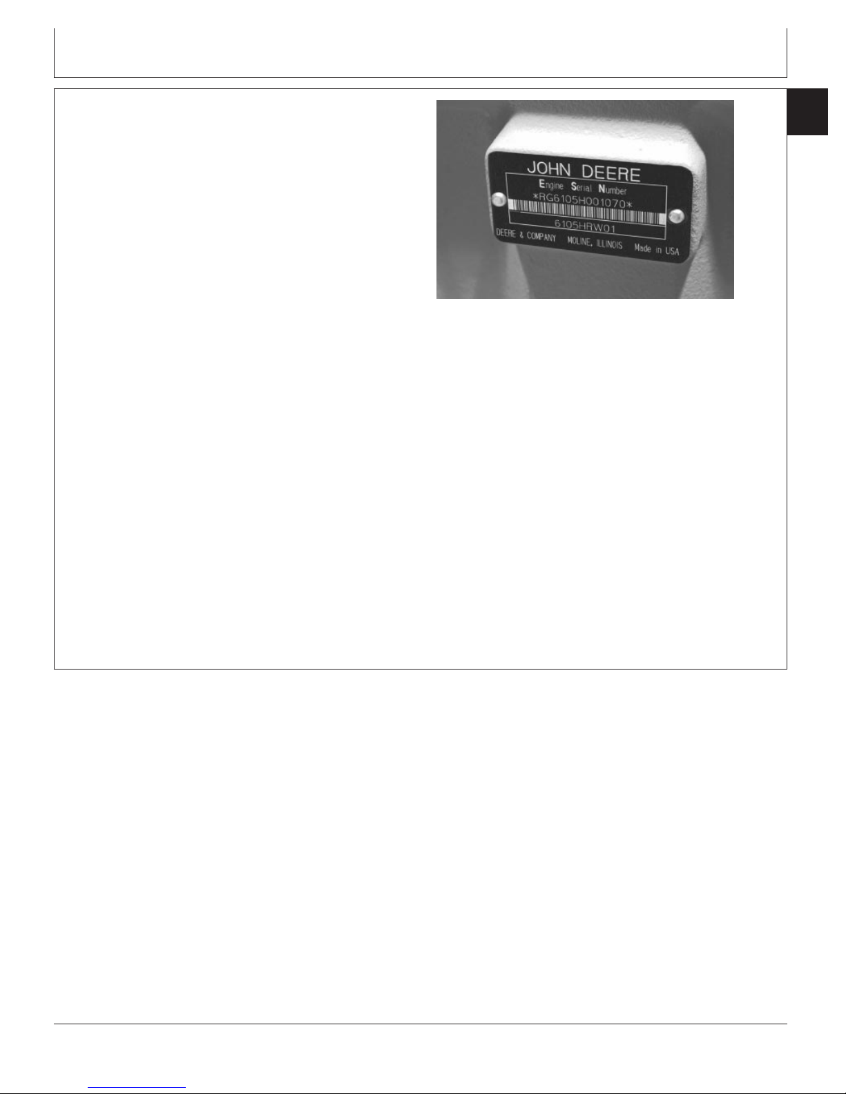
Engine Serial Number Plate Information
2
IMPORTANT: The engine serial number plate can be
easily destroyed. Remove the plate or
record the information elsewhere,
before “hot tank” cleaning the block.
1. Example Engine Serial Number (A)
Each engine has a 13-digit John Deere engine serial
number identifying the producing factory, engine model
designation, and a 6-digit sequential number. The
following is an example:
RG6105H000000
RG ........................................................ Factory code producing engine
6105H ........................................................... Engine model designation
000000 .................................................................... Sequential number
Factory Code Producing Engine
RG ................................................................... Waterloo Engine Works
Engine Model Designation
6105H ..................... See Engine Model Designation on previous page
Example Engine Serial Number Plate
RG8427A –UN–09DEC97
Sequential Number
000000 .......................................................... 6-digit sequential number
2. Engine Application Data (B)
The second line of information on the engine serial
number plate identifies the engine/Deere machine or
OEM relationship. See ENGINE APPLICATION
CHART later in this group.
RG,RG34710,24 –19–07NOV00–1/1
CTM100 (06APR04)
01-001-2
P
OWERTECH
10.5 L & 12.5 L Diesel Engines
040604
PN=26
Page 27

Engine Option Code Label
Engine Identification and Applications
01
001
3
Option Code Label
In addition to the serial number plate, OEM engines
have an engine option code label affixed to the rocker
arm cover. These codes indicate which of the engine
options were installed on your engine at the factory.
RG8740 –UN–12JUL99
When in need of parts or service, furnish your
authorized servicing dealer or engine distributor with
these numbers.
DPSG,OUO1004,917 –19–30JUN99–1/1
CTM100 (06APR04)
01-001-3
P
OWERTECH
10.5 L & 12.5 L Diesel Engines
040604
PN=27
Page 28

Engine Identification and Applications
01
001
Engine Application Chart
4
John Deere Agricultural Equipment Applications
Machine Model No. Engine Model
WATERLOO TRACTORS—4-WHEEL DRIVE
9200 .............................................................................................................................................................. 6105HRW01, 6105HRW02,
9220 .............................................................................................................................................................. 6125HRW10, 6125HRW13,
9300 .............................................................................................................................................................. 6125HRW01, 6125HRW11,
9320 .............................................................................................................................................................. 6125HRW13, 6125HRW16
9400 .............................................................................................................................................................. 6125HRW02, 6125HRW12,
9420 .............................................................................................................................................................. 6125HRW15, 6125HRW17
9520 .............................................................................................................................................................. 6125HRW15, 6125HRW17
9620 .............................................................................................................................................................. 6125HRW18
WATERLOO TRACTORS—TRACK TYPE
9300T ............................................................................................................................................................ 6125HRW03, 6125HRW06
9320T ............................................................................................................................................................ 6125HRW13, 6125HRW16
9400T ............................................................................................................................................................ 6125HRW04, 6125HRW08
9420T ............................................................................................................................................................ 6125HRW15, 6125HRW17
9520T ............................................................................................................................................................ 6125HRW15, 6125HRW17
9620T ............................................................................................................................................................ 6125HRW18
HARVESTER—COMBINES
9860 .............................................................................................................................................................. 6125HH003
ZWEIBRUCKEN—COMBINES/FORAGE HARVESTERS
6750 .............................................................................................................................................................. 6125HZ002, 6125HZ006
6850 .............................................................................................................................................................. 6125HZ001, 6125HZ005
7300 (Europe) ............................................................................................................................................... 6125HZ007
7400 (Europe) ............................................................................................................................................... 6125HZ008
7500 (Europe) ............................................................................................................................................... 6125HZ009
7700 (Europe) ............................................................................................................................................... 6125HZ009
7300 (North America) .................................................................................................................................... 6125HZ011
7400 (North America) .................................................................................................................................... 6125HZ012
7500 (North America) .................................................................................................................................... 6125HZ013
7700 (North America) .................................................................................................................................... 6125HZ013
9880 STS Combine (Europe) ....................................................................................................................... 6125HZ004
CANE HARVESTER (CAMECO—THIBODAUX, LA)
CH2500 ......................................................................................................................................................... 6125AT801
6125HRW05 (30000— )
6125HRW16
6125HRW07 (30000— )
6125HRW09 (30000— )
(30000— )
(30000— )
John Deere Construction and Forestry Equipment
Applications
Machine Model No. Engine Model
744H/HMH Loader ......................................................................................................................................... 6125ADW01, 6125HDW01
LX230 Loader (Hitachi Construction Machinery) .......................................................................................... 6125ADW70
450C LC Excavator ....................................................................................................................................... 6125HT001 (30000— )
824J Loader ................................................................................................................................................... 6125HDW01
844J Loader (production summer 2005) ....................................................................................................... 6125HT003
744J Loader ................................................................................................................................................... 6125HDW01
CTM100 (06APR04)
Continued on next page
01-001-4
P
OWERTECH
RG,RG34710,25 –19–05SEP02–1/2
10.5 L & 12.5 L Diesel Engines
040604
PN=28
Page 29

Engine Identification and Applications
Original Equipment Manufacturers (OEM) Applications
Machine Model No. Engine Model
OEM .............................................................................................................................................................. 6105AF001
6105HF001
6125AF001
6125HF001 (30000— )
6125HF070 (30000— ) Tier II
Marine ........................................................................................................................................................... 6125AFM01, 6125AFM75-Tier II
RG,RG34710,25 –19–05SEP02–2/2
01
001
5
CTM100 (06APR04)
01-001-5
P
OWERTECH
10.5 L & 12.5 L Diesel Engines
040604
PN=29
Page 30

01
001
Engine Identification and Applications
6
CTM100 (06APR04)
01-001-6
P
OWERTECH
10.5 L & 12.5 L Diesel Engines
040604
PN=30
Page 31

Diesel Fuel
Consult your local fuel distributor for properties of the
diesel fuel available in your area.
Group 002
Fuels, Lubricants and Coolant
01
002
1
Fuel lubricity should pass a minimum of 3100 gram
load level as measured by the BOCLE scuffing test.
In general, diesel fuels are blended to satisfy the low
temperature requirements of the geographical area in
which they are marketed.
Diesel fuels specified to EN 590 or ASTM D975 are
recommended.
In all cases, the fuel shall meet the following
properties:
Cetane number of 45 minimum. Cetane number
greater than 50 is preferred, especially for
temperatures below -20°C (-4°F) or elevations above
1500 m (5000 ft).
Cold Filter Plugging Point (CFPP) below the
expected low temperature OR Cloud Point at least
5°C(9°F) below the expected low temperature.
Sulfur content:
• Sulfur content should not exceed 0.5%. Sulfur
content less than 0.05% is preferred.
• If diesel fuel with sulfur content greater than 0.5%
sulfur content is used, reduce the service interval for
engine oil and filter by 50%.
• DO NOT use diesel fuel with sulfur content greater
than 1.0%.
Bio-diesel fuels may be used ONLY if the fuel
properties meet DIN 51606 or equivalent specification.
DO NOT mix used engine oil or any other type of
lubricant with diesel fuel.
OURGP11,000018C –19–12FEB04–1/1
CTM100 (06APR04)
01-002-1
P
OWERTECH
10.5 L & 12.5 L Diesel Engines
040604
PN=31
Page 32

01
002
Bio-Diesel Fuel
2
Consult your local fuel distributor for properties of the
bio-diesel fuel available in your area.
Fuels, Lubricants and Coolant
handling of bio-diesel fuel especially important. Areas
of concern include:
Bio-diesel fuels may be used ONLY if the bio-diesel
fuel properties meet the latest edition of ASTM D6751,
EN 14214, or equivalent specification.
It has been found that bio-diesel fuels may improve
lubricity in concentrations up to a 5% blend (also
known as B5) in petroleum diesel fuel.
When using a blend of bio-diesel fuel, the engine oil
level must be checked daily when the air temperature
is –10°C (14°F) or lower. If oil becomes diluted with
fuel, shorten oil change intervals accordingly.
IMPORTANT: Raw pressed vegetable oils are NOT
acceptable for use as fuel in any
concentration in John Deere
engines.
These oils do not burn completely,
and will cause engine failure by
leaving deposits on injectors and in
the combustion chamber.
A major environmental benefit of bio-diesel fuel is its
ability to biodegrade. This makes proper storage and
• Quality of new fuel
• Water content of the fuel
• Problems due to aging of the fuel
Potential problems resulting from deficiencies in the
above areas when using bio-diesel fuel in
concentrations above 5% may lead to the following
symptoms:
• Power loss and deterioration of performance
• Fuel leakage
• Corrosion of fuel injection equipment
• Coked and/or blocked injector nozzles, resulting in
engine misfire
• Filter plugging
• Lacquering and/or seizure of internal components
• Sludge and sediments
• Reduced service life of engine components
Consult your fuel supplier for additives to improve
storage and performance of bio-diesel fuels.
CTM100 (06APR04)
01-002-2
P
OWERTECH
DX,FUEL7 –19–05JAN04–1/1
10.5 L & 12.5 L Diesel Engines
040604
PN=32
Page 33

Fuels, Lubricants and Coolant
Lubricity of Diesel Fuel
Diesel fuel must have adequate lubricity to ensure
proper operation and durability of fuel injection system
components.
ASTM D975 and EN 590 specifications do not require
fuels to pass a fuel lubricity test.
Sulfur content of diesel fuel for highway use is less
than 0.05% (500 ppm) in the United States and
Canada, and less than 0.035% (350 ppm) in the
European Union.
Experience shows that some low sulfur diesel fuels
may have inadequate lubricity and their use may
reduce performance in fuel injection systems due to
inadequate lubrication of injection pump components.
The lower concentration of aromatic compounds in
01
002
3
these fuels also adversely affects injection pump seals
and may result in leaks.
Use of low lubricity diesel fuels may also cause
accelerated wear, injection nozzle erosion or corrosion,
engine speed instability, hard starting, low power, and
engine smoke.
Fuel lubricity should pass a minimum load level of
3100 grams as measured by ASTM D6078 or
maximum scar diameter of 0.45 mm as measured by
ASTM D6079 or ISO 12156-1.
If fuel of low or unknown lubricity is used, add John
Deere PREMIUM DIESEL FUEL CONDITIONER (or
equivalent) at the specified concentration.
Dieselscan Fuel Analysis
DIESELSCAN is a John Deere fuel sampling program to
help you monitor the quality of your fuel source. It verifies
fuel type, cleanliness, water content, suitability for cold
weather operation, and if fuel is within ASTM
specifications. Check with your John Deere dealer for
availability of DIESELSCAN kits.
DIESELSCAN is a trademark of Deere & Company
DX,FUEL5 –19–19DEC03–1/1
DX,FUEL6 –19–06DEC00–1/1
CTM100 (06APR04)
01-002-3
P
OWERTECH
10.5 L & 12.5 L Diesel Engines
040604
PN=33
Page 34

Fuels, Lubricants and Coolant
01
002
Diesel Engine Break-In Oil
4
New engines are filled at the factory with John Deere
ENGINE BREAK-IN OIL. During the break-in period, add
John Deere ENGINE BREAK-IN OIL as needed to
maintain the specified oil level.
Change the oil and filter after the first 100 hours of
operation of a new or rebuilt engine.
After engine overhaul, fill the engine with John Deere
ENGINE BREAK-IN OIL.
If John Deere ENGINE BREAK-IN OIL is not available,
use a diesel engine oil meeting one of the following during
the first 100 hours of operation:
• API Service Category CE
• API Service Category CD
• API Service Category CC
• ACEA Oil Sequence E2
• ACEA Oil Sequence E1
After the break-in period, use John Deere PLUS-50 or
other diesel engine oil as recommended in this manual.
IMPORTANT: Do not use PLUS-50 oil or engine oils
meeting any of the following during the
first 100 hours of operation of a new or
rebuilt engine:
API CI-4 ACEA E5
API CH-4 ACEA E4
API CG-4 ACEA E3
API CF-4
API CF-2
API CF
These oils will not allow the engine to
break-in properly.
PLUS-50 is a trademark of Deere & Company
CTM100 (06APR04)
01-002-4
P
OWERTECH
DX,ENOIL4 –19–07NOV03–1/1
10.5 L & 12.5 L Diesel Engines
040604
PN=34
Page 35

Fuels, Lubricants and Coolant
Diesel Engine Oil—Non-Certified and Tier I
Certified Engines
Use oil viscosity based on the expected air temperature
range during the period between oil changes.
The following oil is preferred:
01
002
5
• John Deere PLUS-50
The following oil is also recommended:
• John Deere TORQ-GARD SUPREME
Other oils may be used if they meet one or more of the
following:
• API Service Classification CI-4
• API Service Classification CH-4
• API Service Classification CG-4
• API Service Classification CF-4
• ACEA Specification E5
• ACEA Specification E4
• ACEA Specification E3
• ACEA Specification E2
Multi-viscosity diesel engine oils are preferred.
If diesel fuel with sulfur content greater than 0.5% (5000
ppm) is used, reduce the service interval by 50%.
Extended service intervals may apply when John Deere
preferred engine oils are used. Consult your John Deere
dealer for more information.
TS1661 –UN–10OCT97
PLUS-50 is a registered trademark of Deere & Company.
TORQ-GARD SUPREME is a registered trademark of Deere & Company
CTM100 (06APR04)
01-002-5
P
OWERTECH
OUO1082,0000236 –19–17JAN02–1/1
10.5 L & 12.5 L Diesel Engines
040604
PN=35
Page 36

Fuels, Lubricants and Coolant
01
002
Diesel Engine Oil—Tier II Engines
6
Use oil viscosity based on the expected air temperature
range during the period between oil changes.
50˚C 122˚F
The following oil is preferred:
• John Deere PLUS-50
The following oils are also recommended:
• John Deere TORQ-GARD SUPREME
• Oils meeting ACEA Specification E5
Other oils may be used if they meet one or more of the
following:
• API Service Classification CI-4
• API Service Classification CH-4
• ACEA Specification E3
• ACEA Specification E4
Multi-viscosity diesel engine oils are preferred.
Diesel fuel quality and sulfur content must comply with all
existing emissions regulations for the area in which the
engine operates.
If diesel fuel with sulfur content greater than 0.05% (500
ppm) is used, reduce the service interval by 100 hours.
SAE 15W-40
SAE 10W-40
SAE 0W-40
SAE 5W-30
Diesel Engine Oil
40˚C 104˚F
30˚C 86˚F
20˚C 68˚F
10˚C 50˚F
0˚C 32˚F
-10˚C 14˚F
-20˚C -4˚F
-30˚C -22˚F
-40˚C -40˚F
TS1668A –UN–14DEC01
If diesel fuel with sulfur content greater than 0.5% (5000
ppm) is used, reduce the service interval by 50%.
Diesel fuel with sulfur content greater than 1.0% (10,000
ppm) is not recommended.
When John Deere PLUS-50is used along with the
specified John Deere filter, the oil change interval may be
extended from every 250 hours to every 375 hours of
operation.
PLUS-50 is a registered trademark of Deere & Company.
TORQ-GARD SUPREME is a trademark of Deere & Company
CTM100 (06APR04)
01-002-6
P
OWERTECH
OUOD002,0000172 –19–15MAY02–1/1
10.5 L & 12.5 L Diesel Engines
040604
PN=36
Page 37

Fuels, Lubricants and Coolant
Extended Diesel Engine Oil Service Intervals
When John Deere PLUS-50, ACEA E5, or ACEA E4 oils
are used with the specified John Deere filter, the service
interval for engine oil and filter changes may be increased
by 50% but not to exceed a maximum of 500 hours.
If John Deere PLUS-50, ACEA E5, or ACEA E4 oils are
used with other than the specified John Deere filter,
change the engine oil and filter at the normal service
interval.
If John Deere TORQ-GARD SUPREME, API CI-4, API
CH-4, or ACEA E3 oils are used, change the engine oil
and filter at the normal service interval.
Alternative and Synthetic Lubricants
01
002
7
DX,ENOIL8 –19–03NOV03–1/1
Conditions in certain geographical areas may require
lubricant recommendations different from those printed in
this manual.
Some John Deere brand coolants and lubricants may not
be available in your location.
Consult your John Deere dealer to obtain information and
recommendations.
Synthetic lubricants may be used if they meet the
performance requirements as shown in this manual.
The temperature limits and service intervals shown in this
manual apply to both conventional and synthetic oils.
Re-refined base stock products may be used if the
finished lubricant meets the performance requirements.
DX,ALTER –19–15JUN00–1/1
CTM100 (06APR04)
01-002-7
P
OWERTECH
10.5 L & 12.5 L Diesel Engines
040604
PN=37
Page 38

Fuels, Lubricants and Coolant
01
002
Mixing of Lubricants
8
In general, avoid mixing different brands or types of oil.
Oil manufacturers blend additives in their oils to meet
certain specifications and performance requirements.
Mixing different oils can interfere with the proper
functioning of these additives and degrade lubricant
performance.
OILSCANand COOLSCAN
OILSCANand COOLSCAN are John Deere sampling
programs to help you monitor machine performance and
identify potential problems before they cause serious
damage.
Oil and coolant samples should be taken from each
system prior to its recommended change interval.
Consult your John Deere dealer to obtain specific
information and recommendations.
DX,LUBMIX –19–18MAR96–1/1
Check with your John Deere dealer for the availability of
OILSCAN and COOLSCAN kits.
OILSCAN is a registered trademark of Deere & Company.
COOLSCAN is a trademark of Deere & Company.
T6828AB –UN–15JUN89T6829AB –UN–18OCT88
DX,OILSCAN –19–02DEC02–1/1
CTM100 (06APR04)
01-002-8
P
OWERTECH
10.5 L & 12.5 L Diesel Engines
040604
PN=38
Page 39

Fuels, Lubricants and Coolant
Grease
Use grease based on NLGI consistency numbers and the
expected air temperature range during the service interval.
The following greases are preferred:
• John Deere SD POLYUREA GREASE
The following greases are also recommended:
• John Deere HD MOLY GREASE
• John Deere HD LITHIUM COMPLEX GREASE
• John Deere HD WATER RESISTANT GREASE
• John Deere GREASE-GARD
Other greases may be used if they meet the following:
• NLGI Performance Classification GC-LB
IMPORTANT: Some types of grease thickener are not
compatible with others. Consult your
grease supplier before mixing different
types of grease.
01
002
9
TS1667 –UN–30JUN99
CTM100 (06APR04)
01-002-9
P
OWERTECH
DX,GREA1 –19–14NOV03–1/1
10.5 L & 12.5 L Diesel Engines
040604
PN=39
Page 40

Fuels, Lubricants and Coolant
01
002
Diesel Engine Coolant
10
The engine cooling system is filled to provide
year-round protection against corrosion and cylinder
liner pitting, and winter freeze protection to -37°C
(-34°F). If protection at lower temperatures is required,
consult your John Deere dealer for recommendations.
John Deere COOL-GARD Prediluted Coolant is
preferred for service.
John Deere COOL-GARD Prediluted Coolant is
available in either a concentration of 50% ethylene
glycol or a 55% propylene glycol.
Additional recommended coolants
The following engine coolant is also recommended:
Other low silicate ethylene glycol base coolants for
heavy-duty engines may also be used if they meet one
of the following specifications:
• ASTM D4985 ethylene glycol base prediluted (50%)
coolant
• ASTM D4985 ethylene glycol base coolant
concentrate in a 40% to 60% mixture of concentrate
with quality water
Coolants meeting ASTM D4985 require an initial
charge of supplemental coolant additives, formulated
for protection of heavy duty diesel engines against
corrosion and cylinder liner erosion and pitting. They
also require periodic replenishment of additives during
the drain interval.
• John Deere COOL-GARD Coolant Concentrate in a
40% to 60% mixture of concentrate with quality
water.
John Deere COOL-GARD coolants do not require use
of supplemental coolant additives, except for periodic
replenishment of additives during the drain interval.
Other fully formulated coolants
Other fully formulated low silicate ethylene or
propylene glycol base coolants for heavy-duty engines
may be used if they meet one of the following
specifications:
• ASTM D6210 prediluted (50%) coolant
• ASTM D6210 coolant concentrate in a 40% to 60%
mixture of concentrate with quality water
Coolants meeting ASTM D6210 do not require use of
supplemental coolant additives, except for periodic
replenishment of additives during the drain interval.
Coolants requiring supplemental coolant additives
Other coolants
If a coolant known to meet the requirements of coolant
specifications shown in this manual is not available,
use either:
• ethylene glycol or propylene glycol base prediluted
(40% to 60%) coolant
• ethylene glycol or propylene glycol base coolant
concentrate in a 40% to 60% mixture of concentrate
with quality water
The coolant concentrate or prediluted coolant shall be
of a quality that provides cavitation protection to cast
iron and aluminum parts in the cooling system.
Water quality
Water quality is important to the performance of the
cooling system. Distilled, deionized, or demineralized
water is recommended for mixing with ethylene glycol
and propylene glycol base engine coolant concentrate.
COOL-GARD is a trademark of Deere & Company
CTM100 (06APR04)
Continued on next page
01-002-10
P
OWERTECH
DX,COOL3 –19–19DEC03–1/2
10.5 L & 12.5 L Diesel Engines
040604
PN=40
Page 41

Fuels, Lubricants and Coolant
IMPORTANT: Do not use cooling system sealing
additives or antifreeze that contains
sealing additives.
Supplemental Coolant Additives
IMPORTANT: Do not mix ethylene glycol and
propylene glycol base coolants.
DX,COOL3 –19–19DEC03–2/2
01
002
11
The concentration of coolant additives is gradually
depleted during engine operation. For all
recommended coolants, replenish additives between
drain intervals by adding a supplemental coolant
additive every 12 months or as determined necessary
by coolant testing.
John Deere COOLANT CONDITIONER is
recommended as a supplemental coolant additive in
John Deere engines.
IMPORTANT: Do not add a supplemental coolant
additive when the cooling system is
drained and refilled with John
DeereCOOL-GARD.
COOL-GARD is a trademark of Deere & Company
If other coolants are used, consult the coolant supplier
and follow the manufacturer’s recommendation for use
of supplemental coolant additives.
The use of non-recommended supplemental coolant
additives may result in additive drop-out and gelation
of the coolant.
Add the manufacturer’s recommended concentration of
supplemental coolant additive. DO NOT add more than
the recommended amount.
DX,COOL4 –19–07NOV03–1/1
CTM100 (06APR04)
01-002-11
P
OWERTECH
10.5 L & 12.5 L Diesel Engines
040604
PN=41
Page 42

01
002
Testing Diesel Engine Coolant
12
Testing Diesel Engine Coolant
Maintaining adequate concentrations of glycol and
inhibiting additives in the coolant is critical to protect
the engine and cooling system against freezing,
corrosion, and cylinder liner erosion and pitting.
Test the coolant solution at intervals of 12 months or
less and whenever excessive coolant is lost through
leaks or overheating.
Fuels, Lubricants and Coolant
method to check the freeze point and additive levels of
your engine coolant.
Compare the results to the supplemental coolant
additive (SCA) chart to determine the amount of
inhibiting additives in your coolant and whether more
John Deere COOLANT CONDITIONER should be
added.
COOLSCAN and COOLSCAN PLUS
Coolant test strips
Coolant test strips are available from your John Deere
dealer. These test strips provide a simple, effective
COOLSCAN is a trademark of Deere & Company
COOLSCAN PLUS is a trademark of Deere & Company
For a more thorough evaluation of your coolant,
perform a COOLSCAN or COOLSCAN PLUS analysis,
where available. See your John Deere dealer for
information.
DX,COOL9 –19–19DEC03–1/1
CTM100 (06APR04)
01-002-12
P
OWERTECH
10.5 L & 12.5 L Diesel Engines
040604
PN=42
Page 43
Fuels, Lubricants and Coolant
Replenishing Supplemental Coolant Additives (SCAs) Between Coolant Changes
01
002
13
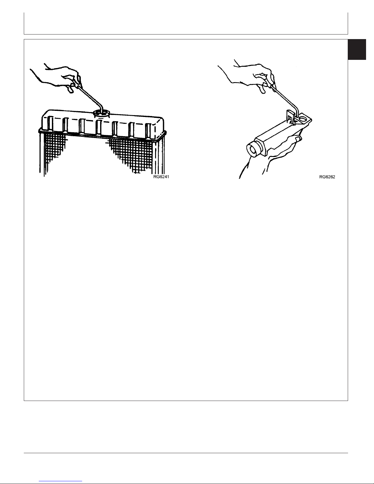
Radiator Coolant Check
IMPORTANT: Do not add supplemental coolant
additives when the cooling system is
drained and refilled with John Deere
ANTIFREEZE/SUMMER COOLANT or
John Deere COOL-GARD.
NOTE: If a system is to be filled with coolant that does
not contain SCAs, the coolant must be
precharged. Determine the total system
capacity and premix with 3% John Deere
Coolant Conditioner.
Through time and use, the concentration of coolant
additives is gradually depleted during engine operation.
Periodic replenishment of inhibitors is required, even
when John Deere ANTIFREEZE/SUMMER COOLANT
is used. The cooling system must be recharged with
additional supplemental coolant additives available in
the form of liquid coolant conditioner.
RG6261 –UN–08DEC97
JT07298 Refractometer
Maintaining the correct coolant conditioner
concentration (SCAs) and freeze point is essential in
your cooling system to protect against rust, liner pitting
and corrosion, and freeze-ups due to incorrect coolant
dilution.
John Deere LIQUID COOLANT CONDITIONER is
recommended as a supplemental coolant additive
in John Deere engines.
DO NOT mix one brand of SCA with a different
brand.
Test the coolant solution at 600 hours or 12 months of
operation using either John Deere coolant test strips or
a COOLSCANanalysis. If a COOLSCANanalysis is
not available, recharge system per instructions printed
on label of John Deere Liquid Coolant Conditioner.
RG6262 –UN–05DEC97
COOL-GARD is a registered trademark of Deere & Company
COOLSCAN is a registered trademark of Deere & Company.
CTM100 (06APR04)
Continued on next page
01-002-13
P
OWERTECH
RG,01,DT7035 –19–14NOV00–1/2
10.5 L & 12.5 L Diesel Engines
040604
PN=43
Page 44

Fuels, Lubricants and Coolant
01
002
IMPORTANT: ALWAYS maintain coolant at correct
14
level and concentration. DO NOT
operate engine without coolant for
even a few minutes.
If frequent coolant makeup is
required, the glycol concentration
should be checked with JT07298
Coolant/Battery Tester to ensure that
the desired freeze point is
maintained. Follow manufacturer’s
instructions provided with
refractometer.
Add the manufacturer’s recommended concentration of
supplemental coolant additive. DO NOT add more than
the recommended amount.
The use of non-recommended supplemental coolant
additives may result in additive drop-out and gelation
of the coolant.
If other coolants are used, consult the coolant supplier
and follow the manufacturer’s recommendation for use
of supplemental coolant additives.
See DIESEL ENGINE COOLANTS AND
SUPPLEMENTAL ADDITIVE INFORMATION earlier in
this group for proper mixing of coolant ingredients
before adding to the cooling system.
Operating in Warm Temperature Climates
John Deere engines are designed to operate using glycol
base engine coolants.
Always use a recommended glycol base engine coolant,
even when operating in geographical areas where freeze
protection is not required.
IMPORTANT: Water may be used as coolant
emergency situations only.
Foaming, hot surface aluminum and
iron corrosion, scaling, and cavitation
will occur when water is used as the
coolant, even when coolant
conditioners are added.
Drain cooling system and refill with
recommended glycol base engine
coolant as soon as possible.
in
RG,01,DT7035 –19–14NOV00–2/2
CTM100 (06APR04)
01-002-14
P
OWERTECH
DX,COOL6 –19–18MAR96–1/1
10.5 L & 12.5 L Diesel Engines
040604
PN=44
Page 45

Fuels, Lubricants and Coolant
Flush and Service Cooling System
CAUTION: Explosive release of fluids from
pressurized cooling system can cause serious
burns. Shut off engine. Only remove filler cap
when cool enough to touch with bare hands.
Slowly loosen cap to first stop to relieve
pressure before removing cap completely.
IMPORTANT: Air must be expelled from cooling
system when system is refilled. Follow
procedure given in your operator’s
manual.
The ethylene glycol base (antifreeze) can become
depleted of SCAs allowing various acids to form that will
damage engine components. In addition, heavy metals,
such as lead, copper and zinc, accumulate in the ethylene
glycol base. The heavy metals come from corrosion that
occurs to some degree with in a cooling system. When a
coolant is saturated to the point where it can no longer
hold heavy metals and other dissolved solids, they settle
out and act as abrasives on engine parts.
01
002
15
TS281 –UN–23AUG88
NOTE: Refer to your operator’s manual for a specific
service interval.
Flush cooling system as described in your operator’s
manual. Clean cooling system with clean water and
TY15979 John Deere Heavy-Duty Cooling System
Cleaner or an equivalent cleaner such as FLEETGUARD
RESTOREor RESTORE PLUS. Follow the instructions
provided with the cleaner. Refill cooling system with the
appropriate coolant solution. See ENGINE COOLANT
SPECIFICATIONS, earlier in this group.
FLEETGUARD is a registered trademark of the Cummins Engine
Company.
RESTORE is a trademark of FLEETGUARD.
RESTORE PLUS is a trademark of FLEETGUARD.
Continued on next page
RG,01,DT7033 –19–29OCT97–1/2
CTM100 (06APR04)
01-002-15
P
OWERTECH
10.5 L & 12.5 L Diesel Engines
040604
PN=45
Page 46

Fuels, Lubricants and Coolant
01
002
IMPORTANT: NEVER overfill the system. A
16
pressurized system needs space for
heat expansion without overflowing at
the top of the radiator. Coolant level
should be at bottom of radiator filler
neck.
Air must be expelled from cooling
system when system is refilled. Loosen
plug in side of thermostat housing to
allow air to escape when filling system.
Retighten plug when all the air has
been expelled.
After adding new coolant solution, run engine until it
reaches operating temperature. This mixes the coolant
solution uniformly and circulates it through the entire
system. After running engine, check coolant level and
entire cooling system for leaks.
Contact your engine servicing dealer, if there are further
questions.
Disposing of Coolant
Improperly disposing of engine coolant can threaten the
environment and ecology.
Use leakproof containers when draining fluids. Do not use
food or beverage containers that may mislead someone
into drinking from them.
Do not pour waste onto the ground, down a drain, or into
any water source.
Inquire on the proper way to recycle or dispose of waste
from your local environmental or recycling center, or from
your engine servicing dealer.
RG,01,DT7033 –19–29OCT97–2/2
TS1133 –UN–26NOV90
RG,01,DT7032 –19–29OCT97–1/1
CTM100 (06APR04)
01-002-16
P
OWERTECH
10.5 L & 12.5 L Diesel Engines
040604
PN=46
Page 47

Section 02
Repair and Adjustments
Contents
Page Page
Group 010—Engine Rebuild Guide, Break-In and
Tune-Up
Engine Overhaul Guidelines ..............02-010-1
Engine Repair Stand....................02-010-1
Safety Precautions .....................02-010-2
Disconnect Turbocharger Oil Inlet Line ......02-010-3
Install Engine Adapter Onto Repair Stand....02-010-3
Engine Lifting Procedure.................02-010-4
Mount Engine Onto Repair Stand ..........02-010-6
Clean Engine .........................02-010-7
6105 and 6125 Engine Disassembly
Sequence ..........................02-010-8
Sealant Application Guidelines ...........02-010-11
6105 and 6125 Engine Assembly
Sequence .........................02-010-13
Engine Break-In Guidelines..............02-010-15
Perform Engine Break-In................02-010-16
Check Crankcase Ventilation System ......02-010-17
Check Air Intake System................02-010-18
Check Exhaust System.................02-010-18
Check and Service Cooling System .......02-010-19
Check Electrical System ................02-010-21
Preliminary Engine Testing Before
Tune-Up ..........................02-010-22
General Tune-Up Recommendations ......02-010-23
Group 020—Cylinder Head and Valves
Remove and Install Rocker Arm Cover ......02-020-1
Clean and Inspect Crankcase Ventilation
Assembly...........................02-020-2
Replace Rocker Arm Cover Gasket.........02-020-3
Check and Adjust Valve Assembly
Clearances and Injector Preload .........02-020-4
Remove Rocker Arm Assembly...........02-020-10 Group 030—Cylinder Block, Liners, Pistons, and
Diagnosing Head Gasket Joint Failures.....02-020-17 Remove and Install Cylinder Block Front
Sequence .........................02-020-19 Preliminary Liner, Piston, and Rod Checks . . .02-030-5
Shaft Assembly .....................02-020-21 Remove Pistons and Connecting Rods ......02-030-7
Checks ...........................02-020-22 Above Block) .......................02-030-11
Assembly..........................02-020-23 or D01073AA Cylinder Liner Puller ......02-030-12
Check Valve Height in Relation to Head
Surface (Valve Recess)...............02-020-23
Remove Valve Assembly................02-020-24
Inspect and Measure Valve Springs .......02-020-25
Inspect Valve Rotators .................02-020-26
Clean, Inspect, and Measure Valves.......02-020-27
Grind Valves .........................02-020-28
Clean and Inspect Cylinder Head .........02-020-29
Check Cylinder Head Flatness ...........02-020-30
Measure Cylinder Head Thickness ........02-020-31
Resurface Cylinder Head Combustion
Face .............................02-020-32
Measure Valve Guide ID................02-020-33
Replace Valve Guides..................02-020-33
Clean and Inspect Valve Seats ...........02-020-34
Grind Valve Seats.....................02-020-35
Remove Valve Seat Inserts..............02-020-36
Measure Valve Seat Bore in Cylinder
Head .............................02-020-37
Install Valve Seat Inserts................02-020-38
Install Valves.........................02-020-38
Replace Unit Injector Sleeve in Cylinder
Head Using JDG981 .................02-020-40
Replace Unit Injector Sleeve in Cylinder
Head Using JDG1184 ................02-020-45
Clean and Inspect Top Deck of Cylinder
Block .............................02-020-55
Measure Cylinder Liner Standout (Height
Above Block) .......................02-020-56
Install Cylinder Head...................02-020-57
Torque-Turn Cylinder Head Cap Screws....02-020-59
Install Rocker Arm Assembly.............02-020-61
Complete Final Assembly for Cylinder Head
Installation .........................02-020-68
RodsRemove Cylinder Head.................02-020-12
Plate ..............................02-030-1Head Gasket Inspection and Repair
Connecting Rods—General Information .....02-030-6Disassemble and Inspect Rocker Arms and
Measure Cylinder Liner Standout (HeightPreliminary Cylinder Head and Valve
Remove Cylinder Liners Using D01062AAAssemble Rocker Arms and Shaft
Continued on next page
02
CTM100 (06APR04)
02-1
P
OWERTECH
10.5 L & 12.5 L Diesel Engines
040604
PN=1
Page 48

Contents
Page Page
Remove Cylinder Liners Using JDG1145 Remove Timing Gear Cover ..............02-040-6
Check Flywheel Housing Face Runout ......02-040-7Cylinder Liner Service Set .............02-030-14
Visually Inspect Cylinder Liners...........02-030-16 Check Flywheel Face Flatness ............02-040-8
02
Remove Flywheel ......................02-040-8Deglaze Cylinder Liners ................02-030-17
Clean Cylinder Liners ..................02-030-18 Inspect and Repair Flywheel ..............02-040-9
Replace Flywheel Ring Gear.............02-040-10Cylinder Liner Manufacturing Date Code
Explanation ........................02-030-19 Remove and Install Flywheel Housing......02-040-11
Install Flywheel .......................02-040-12Disassemble Piston/Rod Assembly and Clean
Piston ............................02-030-20 Remove Rear Crankshaft Oil Seal and
Housing Assembly...................02-040-13Check Piston Compression Ring Groove
Wear—6105 Engines.................02-030-22 Crankshaft and Main Bearing Failure
Analysis...........................02-040-15Check Piston Compression Ring Groove
Wear—6125 Engines.................02-030-23 Remove Crankshaft Main Bearings........02-040-16
Check Main Bearing-to-Journal OilCheck Piston Oil Control Ring Groove
Wear—6105 and 6125 Engines.........02-030-24 Clearance .........................02-040-18
Remove Crankshaft....................02-040-19Inspect Piston Pin and Pin Bore in Piston . . .02-030-25
Determine Piston-to-Liner Clearance.......02-030-26 Inspect Crankshaft ....................02-040-20
Measure Assembled ID of Bearings andMeasure Liner Flange Thickness..........02-030-28
Inspect and Measure Connecting Rod OD of Crankshaft Journals.............02-040-22
Measure Assembled ID of Main BearingBearings ..........................02-030-29
Inspect Connecting Rod and Cap .........02-030-31 Caps (Without Bearings) ..............02-040-23
Crankshaft Grinding Guidelines...........02-040-24Inspect Piston Pins and Rod Bushings .....02-030-34
Remove Piston Pin Bushing, Clean, and Crankshaft Grinding Specifications ........02-040-25
Replace Crankshaft Drive Gear...........02-040-26Inspect Bushing Bore.................02-030-36
Install Piston Pin Bushing ...............02-030-37 Inspect Thrust Bearings ................02-040-27
Thrust Bearing New Part Specifications ....02-040-27Complete Disassembly of Cylinder Block (If
Required)..........................02-030-38 Install Main Bearing Inserts in Block .......02-040-28
Install Crankshaft .....................02-040-29Inspect and Clean Cylinder Block .........02-030-39
Measure Cylinder Block ................02-030-41 Install Crankshaft Rear Oil Seal Housing....02-040-32
Install Crankshaft Rear Oil Seal and WearRecheck Cylinder Liner Standout (Height
Above Block) .......................02-030-43 Sleeve Assembly....................02-040-33
Install Timing Gear Cover ...............02-040-34Install Cylinder Liner O-Rings and
Packings ..........................02-030-44 Install Crankshaft Vibration Damper and
Front Oil Seal ......................02-040-39Install Cylinder Liners ..................02-030-45
Assemble Pistons and Connecting Rods....02-030-47 Complete Final Assembly ...............02-040-43
Install Pistons and Connecting Rods.......02-030-48
Torque-Turn Connecting Rod Cap Group 050—Camshaft and Timing Gear Train
Camshaft Gear Access Cover TorqueScrews............................02-030-52
Check Engine Rotation for Excessive Sequence ..........................02-050-1
Check and Adjust Camshaft-to-CrankshaftTightness..........................02-030-53
Measure Piston Protrusion ..............02-030-53 Timing .............................02-050-2
Adjust Front Timing Gear Backlash.........02-050-4Remove and Install Piston Spray Jets......02-030-54
Complete Final Assembly ...............02-030-55 Remove and Install Camshaft .............02-050-9
Replace Fuel Supply Pump Drive Pin ......02-050-18
Visually Inspect Camshaft and RollerGroup 040—Crankshaft, Main Bearings, and
Flywheel Followers..........................02-050-18
Inspect and Measure Camshaft BushingCrankshaft Vibration Damper Torque
Sequence ..........................02-040-1 ID and Journal OD...................02-050-19
Measure Camshaft Lobe Lift Height .......02-050-20Inspect Crankshaft Vibration Damper .......02-040-2
Check Crankshaft End Play ..............02-040-3 Inspect Camshaft Position Sensor Lobe ....02-050-20
Replace Camshaft Bushings .............02-050-21Remove Crankshaft Vibration Damper and
Pulley .............................02-040-4
Remove Crankshaft Front Oil Seal .........02-040-5
Continued on next page
CTM100 (06APR04)
02-2
P
OWERTECH
10.5 L & 12.5 L Diesel Engines
040604
PN=2
Page 49

Contents
Page Page
SAE “A” (Front) and SAE “B” (Rear) Auxiliary Repair Turbocharger ...................02-080-14
Prelube Turbocharger ..................02-080-15Drive Assembly .....................02-050-26
SAE “B” Rear Auxiliary Drive.............02-050-27 Install Turbocharger ...................02-080-16
Align SAE “A” Front Auxiliary Drive Turbocharger Break-In .................02-080-17
Remove, Inspect, and Install ExhaustAdapter ...........................02-050-28
Manifold...........................02-080-18
Remove, Inspect, and Install IntakeGroup 060—Lubrication System
Oil Filter and Oil Conditioning Housing Manifold...........................02-080-21
Remove and Install Aftercooler AssemblyAssembly...........................02-060-1
Remove Oil Filter and Valve Housing/Oil (6105A and 6125A Engines) ...........02-080-23
Inspect and Repair Aftercooler (6105A andCooler Cover and Valve Housing.........02-060-2
Inspect and Replace Oil Filter Adapter ......02-060-2 6125A Engines).....................02-080-25
Remove, Inspect, and Install Oil Pressure
Regulating Valve .....................02-060-3 Group 090—Fuel System
Fuel System ..........................02-090-1Remove, Inspect, and Install Oil Cooler
and Oil Filter Bypass Valves ............02-060-4
Remove, Inspect, and Install Oil Pressure Group 100—Starting and Charging Systems
Remove and Install Alternator (OEMRelief Valve (If Equipped) ..............02-060-5
Remove, Clean, and Inspect Engine Oil Engines) ...........................02-100-1
Remove and Install Starter Motor (OEMCooler .............................02-060-6
Install Oil Cooler/Oil Filter Valve Housing Engines) ...........................02-100-2
Assembly or Oil Cooler Cover/Valve Housing
Assembly...........................02-060-8
Remove Engine Oil Pump...............02-060-10
Clean and Inspect Oil Pump and Drive
Gear .............................02-060-11
Install Engine Oil Pump.................02-060-12
Remove Engine Oil Pan ................02-060-13
Remove and Install Oil Pickup Tube .......02-060-14
Install Engine Oil Pan ..................02-060-15
02
Group 070—Cooling System
Replace Bearings in Fan Drive Assembly ....02-070-1
Inspect and Check Belt Tensioner Spring
Tension ............................02-070-5
Replace Belt Tensioner Assembly..........02-070-7
Remove Coolant Pump..................02-070-8
Clean and Inspect Coolant Pump Parts......02-070-9
Install Coolant Pump...................02-070-10
Remove Thermostats ..................02-070-11
Install Thermostats ....................02-070-12
Test Thermostat Opening Temperature.....02-070-13
Remove and Install Thermostat Housing....02-070-14
Remove and Install Coolant Heater—if
Equipped ..........................02-070-15
Group 080—Air Intake and Exhaust System
Extending Turbocharger Life ..............02-080-1
Remove Turbocharger...................02-080-3
Turbocharger Failure Analysis.............02-080-4
Turbocharger Seven-Step Inspection .......02-080-6
Perform Radial Bearing Clearance Test ....02-080-13
Perform Axial Bearing End Play Test ......02-080-14
CTM100 (06APR04)
02-3
P
OWERTECH
10.5 L & 12.5 L Diesel Engines
040604
PN=3
Page 50

02
Contents
CTM100 (06APR04)
02-4
P
OWERTECH
10.5 L & 12.5 L Diesel Engines
040604
PN=4
Page 51

Engine Rebuild Guide, Break-In and Tune-Up
Engine Overhaul Guidelines
Engine life and performance will vary depending on
operating conditions and the level of regular engine
maintenance. Engines can be brought back to original
performance standards through proper overhaul procedure
and replacement of parts with genuine John Deere service
parts. Overhauling the engine prior to failure can avoid
costly repairs and downtime.
Consider installing a John Deere overhaul kit when:
• The engine begins to experience power loss and there
are no known engine component failures.
• The engine is hard to start due to low cranking
compression.
• The engine begins to smoke and there are no known
engine component failures.
• The engine begins to use oil. Refer to Section 04 for
acceptable oil consumption.
• The engine has high usage hours and the owner wants
to take preventive measure to avoid high-cost repairs
and costly downtime.
Group 010
02
010
1
John Deere overhaul kits have a 1500-hour or 12-month
warranty, whichever comes first. Installation labor is
covered by warranty if an authorized John Deere dealer
installed the overhaul kit and the replacement parts.
Engine Repair Stand
NOTE: Only the 2722 kg (6000 lb) heavy-duty engine
repair stand (A) No. D05223ST manufactured by
Owatonna Tool Co., Owatonna, Minnesota is
referenced in this manual. When any other repair
stand is used, consult the manufacturer’s
instructions for mounting the engine.
Refer to machine technical manual for steps to remove
engine from machine before installing it on repair stand.
A—Engine Repair Stand
DPSG,OUO1032,3410 –19–15JUN00–1/1
CTM100 (06APR04)
02-010-1
Engine Repair Stand
P
OWERTECH
RG4929 –UN–05DEC97
RG,RG34710,1043 –19–23OCT97–1/1
10.5 L & 12.5 L Diesel Engines
040604
PN=49
Page 52

Safety Precautions
Engine Rebuild Guide, Break-In and Tune-Up
The engine repair stand should be used only by
qualified service technicians familiar with this
equipment.
02
010
To maintain shear strength specifications, alloy steel
2
Class 12.9 or SAE Grade 8 or higher cap screws must
be used to mount adapters and engine to repair stand.
Use LOCTITE242 Thread Lock and Sealer on cap
screws when installing lifting straps on engine. Tighten
cap screws to specifications given.
For full thread engagement, be certain that tapped
holes in adapters and engine blocks are clean and not
damaged. A thread length engagement equal to 1-1/2
screw diameters minimum is required to maintain
strength requirements.
To avoid structural or personal injury, do not exceed
the maximum capacity rating of 2722 kg (6000 lb).
Maximum capacity is determined with the center of the
engine located not more than 330 mm (13 in.) from the
mounting hub surface of the engine stand.
The center of balance of an engine must be located
within 51 mm (2 in.) of the engine stand rotating shaft.
Engine center of balance is generally located a few
millimeters above the crankshaft.
To prevent possible personal injury due to engine
slippage, recheck to make sure engine is solidly
mounted before releasing support from engine lifting
device.
Never permit any part of the body to be positioned
under a load being lifted or suspended. Accidental
slippage may result in personal injury.
The lifting jack is to be used when it is necessary to lift
the engine for rotation. When working on the engine,
the jack should be at its lowest position to keep the
center of gravity and the possibility of tipping low.
To prevent possible personal injury due to sudden
engine movement, lower the engine by operating jack
release valve slowly. Do not unscrew release valve
knob more than two turns from its closed position.
LOCTITE is a registered trademark of Loctite Corp.
CTM100 (06APR04)
02-010-2
P
OWERTECH
RG,RG34710,45 –19–30SEP97–1/1
10.5 L & 12.5 L Diesel Engines
040604
PN=50
Page 53

Engine Rebuild Guide, Break-In and Tune-Up
Disconnect Turbocharger Oil Inlet Line
1. Drain all engine oil and coolant, if not previously done.
IMPORTANT: When servicing turbocharged engines
on a rollover stand, disconnect
turbocharger oil inlet line (A) from oil
filter housing or turbocharger before
rolling engine over. Failure to do so
may cause a hydraulic lock upon
starting engine. Hydraulic lock may
cause possible engine failure.
Hydraulic lock occurs when trapped oil
in the oil filter housing drains through
the turbocharger, the exhaust and
intake manifolds, and then into the
cylinder head.
After starting the engine, the trapped oil
in the manifold and head is released
into the cylinder(s) filling them with oil
causing hydraulic lock and possible
engine failure.
2. Disconnect turbocharger oil inlet line at turbocharger or
oil filter base.
02
010
3
RG10241 –UN–09JUL99
Turbocharger Oil Inlet Line
A—Turbocharger Oil Inlet Line
Install Engine Adapter Onto Repair Stand
Attach the No. 205466 Adapter Assembly to engine repair
stand using four 5/8-11 x 2 in. SAE Grade 8 (or higher
grade) cap screws. Tighten cap screws to specification.
Specification
Engine Adapter-to-Repair Stand
Cap Screws—Torque 135 N•m (100 lb-ft)..................................................
CTM100 (06APR04)
02-010-3
DPSG,OUO1004,918 –19–30JUN99–1/1
D05223ST Repair Stand with 205466 Adapter
RG,RG34710,46 –19–21AUG02–1/1
P
OWERTECH
10.5 L & 12.5 L Diesel Engines
RG8183 –UN–08DEC97
040604
PN=51
Page 54
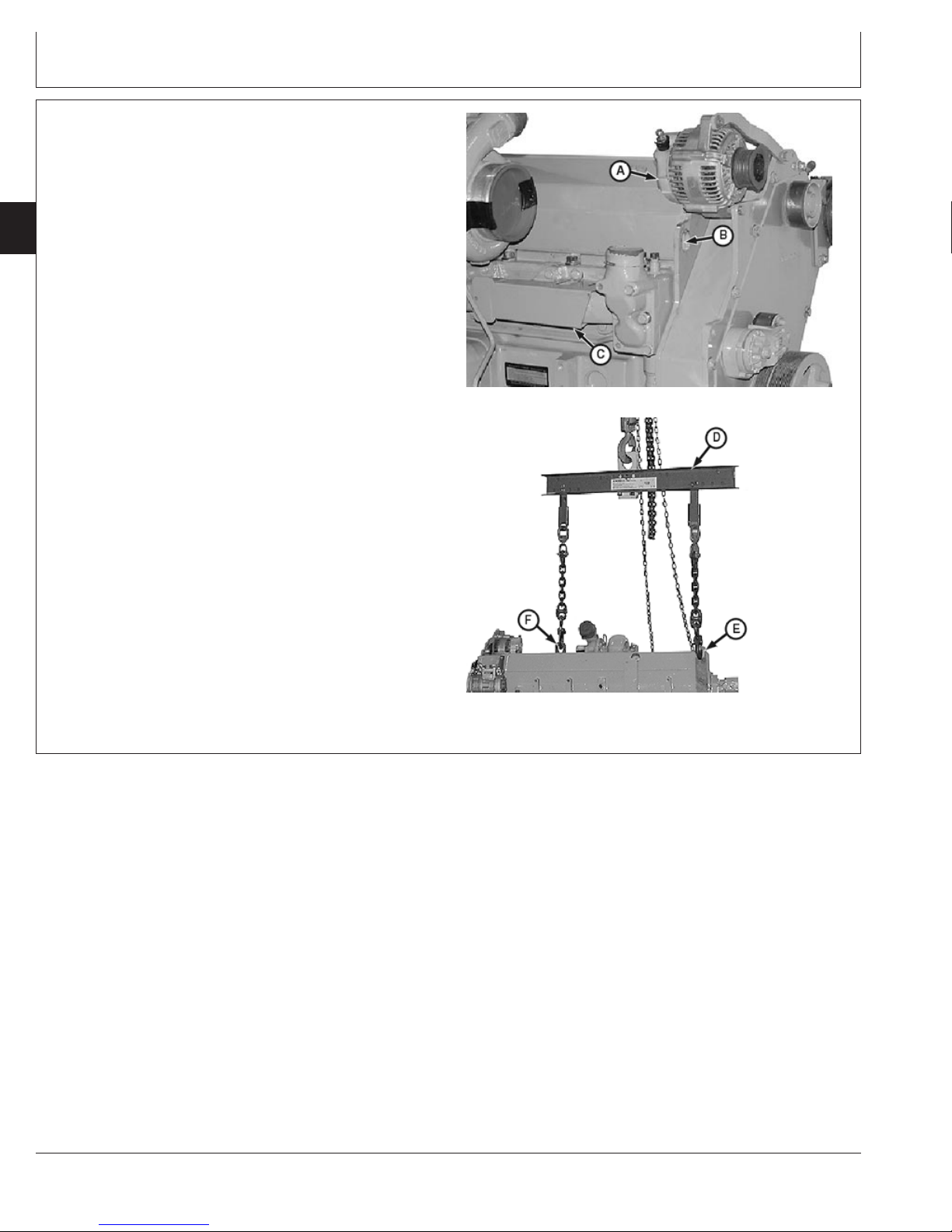
Engine Rebuild Guide, Break-In and Tune-Up
Engine Lifting Procedure
1. Install R503481 (OEM & AT801 Applications Only) or
R128001 Front Lift Strap and R128000 Rear Lift Strap
02
010
(or attach sling to front plate lift eye) and tighten cap
screws to specification.
4
Specification
Engine Lift Strap Cap Screws—
Torque 90 N•m (66 lb-ft).............................................................................
NOTE: Lift spacing on sling is adjustable. Position each
lifting point so that engine hangs level when lifted.
2. Attach the JDG23 Engine Lifting Sling (D) to lift straps
and overhead hoist or floor crane of adequate lifting
capacity.
3. Carefully lift engine to desired location.
A—Alternator
B—Front Plate Lift Eye
C—Exhaust Shield
D—JDG23 Lift Sling
E—R128000 Rear Lift Strap
F—R503481 (OEM & AT801 Applications Only) or
R128001 Front Lift Strap
1
Can be ordered from parts catalog.
1
1
Continued on next page
Engine Lift Points
RG10349 –UN–13OCT99
RG10350 –UN–13OCT99
Engine Lifting
RG,RG34710,47 –19–20AUG02–1/2
CTM100 (06APR04)
02-010-4
P
OWERTECH
10.5 L & 12.5 L Diesel Engines
040604
PN=52
Page 55

Engine Rebuild Guide, Break-In and Tune-Up
IMPORTANT: Lifting straps are designed to lift the
engine and small accessories such as
hydraulic pumps and air compressors
mounted to the engine auxiliary gear
drive, or belt-driven components, such
as air conditioning compressors and
alternators. If larger components, such
as PTO’s, transmissions, generators or
air compressors, are attached to other
locations on the engine, the lift straps
provided with the engine are not
intended for this purpose. Technician is
responsible for providing adequate
lifting devices under these situations.
See machine technical manual for
additional information on removing
engine from machine.
CAUTION: The only approved method for lifting
the 6105 and 6125 Engine is with the use of
JDG23 Lifting Sling (D), R128000 Rear Lift Strap
(E) and R503481 (OEM & AT801 Applications
Only) or R128001 Front Lift Strap (F). The front
plate lift eye (B) can be used as a lifting point
instead of R503481 (OEM & AT801 Applications
Only) or R128001 Front Lift Strap. Use extreme
caution when lifting and NEVER permit any part
of the body to be positioned under an engine
being lifted or suspended.
02
010
5
Lift engine with longitudinal loading on lift sling
and lifting brackets only. Angular loading
greatly reduces lifting capacity of sling and
brackets.
IMPORTANT: Ensure that engine lifting straps are
secured with Class 12.9 (or higher
class) cap screws. Apply TY9370
LOCTITE242 Thread Lock and Sealer
to lift strap cap screws.
NOTE: If lift eye in front plate (B) is used instead of
R503481 (OEM & AT801 Applications Only) or
R128001 Front Lift Strap, remove alternator (A).
If front lift strap (F) is being used, remove exhaust
shield (C) and install lift strap using shield
mounting cap screw holes.
LOCTITE is a registered trademark of Loctite Corp.
CTM100 (06APR04)
02-010-5
P
OWERTECH
RG,RG34710,47 –19–20AUG02–2/2
10.5 L & 12.5 L Diesel Engines
040604
PN=53
Page 56

Mount Engine Onto Repair Stand
CAUTION: NEVER remove the overhead lifting
equipment until the engine is securely mounted
02
010
6
1. Remove starter motor (A).
onto the repair stand and all mounting
hardware is tightened to specified torque.
Always release the overhead lifting equipment
slowly.
Engine Rebuild Guide, Break-In and Tune-Up
2. On engines with primary fuel filter/water separator (B)
on left side of engine, remove primary fuel filter/water
separator.
On later engines with large single fuel filter mounted on
left side of engine, remove fuel filter assembly.
IMPORTANT: DO NOT use shorter cap screws than
recommended since mounting threads
in block bore may be stripped when
tightening to specified torque. USE
ONLY JDG980 METRIC BOLT KIT for
mounting engine to repair stand.
Component Removal for Repair Stand Mounting
RG8184A –UN–05DEC97
A—Starter Motor
B—Primary Fuel Filter
RG,RG34710,48 –19–13SEP02–1/3
3. Mount engine to front engine adapter using two1M16 x
2.0 x 65 mm (Class 12.9) cap screws (A). Tighten cap
screws to specification.
Engine-to-Stand Adapter Cap
Screws—Torque 400 N•m (300 lb-ft)..........................................................
1
From JDG980 Metric Bolt Kit.
Specification
CTM100 (06APR04)
Continued on next page
02-010-6
Front Repair Stand Cap Screws
A—Cap Screws
P
OWERTECH
RG8185 –UN–05DEC97
RG,RG34710,48 –19–13SEP02–2/3
10.5 L & 12.5 L Diesel Engines
040604
PN=54
Page 57

Engine Rebuild Guide, Break-In and Tune-Up
4. Mount engine to rear engine adapter using two1M16 x
2.0 x 65 mm (Class 12.9) cap screws (B). Tighten cap
screws to specification.
Engine-to-Stand Adapter Cap
Screws—Torque 400 N•m (300 lb-ft)..........................................................
B—Cap Screws
1
From JDG980 Metric Bolt Kit.
Specification
Clean Engine
1. Cap or plug all openings (air intake, exhaust, fuel,
coolant, etc.).
2. Remove electrical components (starter, alternator,
etc.). Cover electrical components that are not
removed with plastic and tape securely to prevent
moisture damage.
02
010
7
RG8186 –UN–05DEC97
Rear Repair Stand Cap Screws
RG,RG34710,48 –19–13SEP02–3/3
3. Thoroughly steam clean engine.
IMPORTANT: Never steam clean or pour cold water
on an engine while it is still hot. To do
so may cause seizure of precision
parts.
6125HRW Engine on Repair Stand
RG8188 –UN–21MAY98
RG,RG34710,49 –19–21DEC00–1/1
CTM100 (06APR04)
02-010-7
P
OWERTECH
10.5 L & 12.5 L Diesel Engines
040604
PN=55
Page 58

Engine Rebuild Guide, Break-In and Tune-Up
6105 and 6125 Engine Disassembly Sequence
The following sequence is suggested when complete
engine disassembly for overhaul is required. Refer to
the appropriate repair group when removing individual
02
components.
010
8
Procedure Reference
Drain all coolant, fuel and engine oil. See DISPOSING OF COOLANT in Section 01, Group 002.
Perform John Deere COOLSCAN and OILSCANanalysis. Dispose See OILSCAN AND COOLSCAN in Section 01, Group 002.
of remaining fluids properly. See TESTING DIESEL ENGINE COOLANT in Section 01, Group
Remove starter motor. See REMOVE AND INSTALL STARTER MOTOR in Group 100.
Remove fuel filter assemblies with mounting bases as required See REPLACING PRIMARY FUEL FILTER/WATER SEPARATOR in
(Delphi/Lucas ECU controlled fuel system). CTM115, Section 02, Group 090.
Remove fuel filter assemblies with mounting bases as required (John See REPLACING PRIMARY FUEL FILTER/WATER SEPARATOR in
Deere Level 6 ECU controlled fuel system). CTM188, Section 02, Group 090 (dual rail fuel systems).
Mount engine onto recommended safety approved repair stand. See MOUNT ENGINE ONTO REPAIR STAND in this group.
Remove fan, drive belts, and fan drive assembly. See Group 070.
Remove alternator. See REMOVE AND INSTALL ALTERNATOR in Group 100.
Remove compressor. See CTM67, OEM Engine Accessories.
Remove vibration damper and pulley assembly from crankshaft. See REMOVE CRANKSHAFT VIBRATION DAMPER AND PULLEY
Disconnect all air intake/exhaust piping and turbocharger oil See REMOVE TURBOCHARGER in Group 080.
inlet/drain lines. Remove turbocharger.
Remove exhaust manifold and gaskets. See REMOVE, INSPECT AND INSTALL EXHAUST MANIFOLD in
Remove oil filter and oil filter housing. See REMOVE OIL FILTER AND VALVE HOUSING/OIL COOLER
Remove oil cooler assembly. See REMOVE, CLEAN AND INSPECT ENGINE OIL COOLER in
Remove coolant pump assembly. See REMOVE COOLANT PUMP in Group 070.
Remove water manifold/thermostat housing assembly. See REMOVE AND INSTALL THERMOSTAT HOUSING in Group
Remove all six piston spray jets. See REMOVE AND INSTALL PISTON SPRAY JETS in Group 030.
ENGINE DISASSEMBLY SEQUENCE
(Continued on next page)
NOTE: Remove starter motor and primary fuel
filter/water separator before mounting engine
onto repair stand.
002.
See REPLACE FINAL (SECONDARY) FUEL FILTER ELEMENT in
CTM115, Section 02, Group 090.
See REPLACE FINAL (SECONDARY) FUEL FILTER ELEMENT in
CTM188, Section 02, Group 090 (dual rail fuel systems).
See FUEL FILTER/WATER SEPARATOR ASSEMBLY in CTM188,
Section 02, Group 091 (single rail fuel systems).
in Group 040.
Group 080.
COVER AND VALVE HOUSING in Group 060.
Group 060.
070.
COOLSCAN is a trademark of Deere & Company.
OILSCAN is a registered trademark of Deere & Company.
CTM100 (06APR04)
Continued on next page
02-010-8
P
OWERTECH
RG,RG34710,50 –19–21AUG02–1/3
10.5 L & 12.5 L Diesel Engines
040604
PN=56
Page 59

Engine Rebuild Guide, Break-In and Tune-Up
ENGINE DISASSEMBLY SEQUENCE—CONTINUED
Procedure Reference
On 6105H and 6125H engines, remove air intake manifold. See REMOVE, INSPECT AND INSTALL INTAKE MANIFOLD in
On 6105A and 6125A engines, remove aftercooler assembly. See REMOVE AND INSTALL AFTERCOOLER ASSEMBLY in Group
Remove fuel supply pump (Delphi/Lucas ECU controlled fuel system). See REMOVE AND INSTALL FUEL SUPPLY PUMP in CTM115,
Remove fuel supply pump (John Deere ECU controlled fuel system). See REMOVE AND INSTALL FUEL SUPPLY PUMP in CTM188,
Remove fuel manifold assembly on Delphi/Lucas ECU controlled fuel See REMOVE AND INSTALL FUEL MANIFOLD in CTM 115, Section
systems. 02, Group 090.
Remove fuel manifold assembly on John Deere ECU controlled fuel See REMOVE AND INSTALL FUEL MANIFOLD in CTM 188, Section
systems. 02, Group 090 (dual rail fuel systems).
Remove all remaining fuel lines, identify for reassembly in correct See CTM115, Section 02, Group 090.
location. See CTM188, Section 02, Group 090 or 091.
Remove engine oil pan. See REMOVE ENGINE OIL PAN in Group 060.
Remove oil pickup tube. See REMOVE AND INSTALL OIL PICKUP TUBE in Group 060.
Remove front gear train access cover and timing gear cover. See REMOVE TIMING GEAR COVER in Group 040.
Remove rocker arm cover. See REMOVE AND INSTALL ROCKER ARM COVER in Group 020.
NOTE: Identify valve train components and electronic unit injectors
for reassembly in same location as removed.
Remove front and rear rocker arm and shaft assembly and EUI
wiring harness.
Group 080.
080.
Section 02, Group 090.
Section 02, Group 090 (dual rail fuel systems).
See REMOVE AND INSTALL FUEL SUPPLY PUMP in CTM188,
Section 02, Group 091 (single rail fuel systems).
See REMOVE ROCKER ARM ASSEMBLY in Group 020.
02
010
9
Remove electronic unit injectors on Delphi/Lucas ECU controlled fuel See REMOVE AND INSTALL ELECTRONIC UNIT INJECTORS in
systems. CTM115, Section 02, Group 090.
Remove electronic unit injectors on John Deere ECU controlled fuel See REMOVE AND INSTALL ELECTRONIC UNIT INJECTORS in
systems. CTM188, Section 02, Group 090 (dual rail fuel systems).
Remove camshaft gear and idler gear assembly. Remove camshaft See REMOVE AND INSTALL CAMSHAFT in Group 050.
position sensor and remove camshaft.
Remove oil pump drive gear and remove oil pump assembly. See REMOVE ENGINE OIL PUMP in Group 060.
Remove cylinder head and gasket. See REMOVE CYLINDER HEAD in Group 020.
Remove flywheel. See REMOVE FLYWHEEL in Group 040.
Remove flywheel housing. See REMOVE AND INSTALL FLYWHEEL HOUSING in Group 040.
Remove rear crankshaft seal and seal housing. See REMOVE REAR CRANKSHAFT OIL SEAL AND HOUSING
(Continued on next page)
See REMOVE AND INSTALL ELECTRONIC UNIT INJECTORS in
CTM188, Section 02, Group 091 (single rail fuel systems).
ASSEMBLY in Group 040.
CTM100 (06APR04)
Continued on next page
02-010-9
P
OWERTECH
RG,RG34710,50 –19–21AUG02–2/3
10.5 L & 12.5 L Diesel Engines
040604
PN=57
Page 60

Engine Rebuild Guide, Break-In and Tune-Up
ENGINE DISASSEMBLY SEQUENCE—CONTINUED
Procedure Reference
Remove cylinder block front plate. See REMOVE AND INSTALL CYLINDER BLOCK FRONT PLATE in
Perform wear checks on connecting rod bearing surfaces using See REMOVE PISTONS AND CONNECTING RODS in Group 030.
02
PLASTIGAGE. Remove piston and connecting rod assemblies.
010
10
Check crankshaft end play. See CHECK CRANKSHAFT END PLAY in Group 040.
Remove main bearing caps with bearings. Perform wear checks on See REMOVE CRANKSHAFT MAIN BEARINGS in Group 040.
main bearing surfaces with PLASTIGAGE. See CHECK MAIN BEARING-TO-JOURNAL OIL CLEARANCE in
Remove crankshaft. See REMOVE CRANKSHAFT in Group 040.
Remove cylinder block plugs and serial number plate if block is to be See COMPLETE DISASSEMBLY OF CYLINDER BLOCK in Group
put in a hot tank. 030.
Inspect and repair individual components. See appropriate repair groups.
Group 030.
Group 040.
PLASTIGAGE is a registered trademark of the DANA Corp.
RG,RG34710,50 –19–21AUG02–3/3
CTM100 (06APR04)
02-010-10
P
OWERTECH
10.5 L & 12.5 L Diesel Engines
040604
PN=58
Page 61

Engine Rebuild Guide, Break-In and Tune-Up
Sealant Application Guidelines
Listed below are sealants which have been tested and
are used by the John Deere factory to control leakage
and ensure hardware retention. ALWAYS use the
following recommended sealants when assembling
your John Deere Diesel Engine to ensure quality
performance.
LOCTITEthread sealants are designed to perform to
sealing standards with machine oil residue present. If
excessive machine oil or poor cleanliness quality exist,
clean with solvent. Refer to John Deere Merchandise
and Parts Sales Manual for ordering information.
IMPORTANT: LOCTITEgasket materials are NOT
designed to work with oil residue
present. Oil residues must be
cleaned from surfaces before
applying gasket material.
LOCTITE242 Thread Lock & Sealer (Medium
Strength) (blue):
TY9370 6 mL (0.2 oz) tube
• Threaded plugs and fittings: cylinder block (oil
galley).
• Cap screws: coolant pump, timing gear cover,
camshaft gear access cover, oil pump.
• Oil pressure sending unit.
• Turbocharger oil inlet fitting.
• Fuel filter check valve or elbow (filter header end)
dual rail fuel system.
• Piston spray jets.
• Timing gear cover gasket and camshaft gear access
cover gasket on earlier engines using Fel-Pro
gaskets.
• Idler gear carrier cap screws, camshaft gear retainer
cap screws and fuel supply pump drive coupler cap
screws.
• EUI hold-down clamp cap screws.
TY9371 6 mL (0.2 oz) tube
• Oil filter adapter-to-base.
LOCTITE277 Thread Lock & Sealer (High
Strength) (red):
T43514 50 mL (1.7 oz) bottle
• Expansion plugs in cylinder head and block.
LOCTITE515 Flexible Sealant (General Purpose)
(purple):
TY6304 50 mL (1.7 oz) bottle
• Timing gear cover and camshaft gear access cover
gasket on earlier engines using Fel-Pro gasket.
LOCTITE592 Pipe Sealant with TEFLON(white):
TY9374 6 mL (0.2 oz) tube
• Pipe plugs: cylinder block (water manifold),
thermostat housing, air intake manifold, and coolant
pump.
• Temperature sending unit.
• Coolant heater.
• Oil pan drain valve/hose.
LOCTITE680 Maximum Strength Retaining
Compound (green):
TY15969 6 mL (0.2 oz) tube
• Crankshaft flange and ID of front wear sleeve for
front and rear oil seal/wear sleeve installation.
• Steel cup plugs on cylinder head and block.
02
010
11
LOCTITE271 Thread Lock & Sealer (High
Strength) (clear):
LOCTITE is a registered trademark of Loctite Corp.
TEFLON is a registered trademark of Du Pont Company
CTM100 (06APR04)
Continued on next page
02-010-11
P
OWERTECH
RG,RG34710,51 –19–16OCT00–1/2
10.5 L & 12.5 L Diesel Engines
040604
PN=59
Page 62

Engine Rebuild Guide, Break-In and Tune-Up
PT569 NEVER-SEEZCompound
PT569 227 g (8 oz) Brush
PT506 453 g (16 oz) Spray
02
010
• Cap Screws: exhaust manifold, intake manifold,
12
aftercooler, turbocharger oil return line, and
turbocharger cap screws/nut.
LOCTITE222 Small Screw Threadlocker
(Removable) (Purple)
TY24311 0.5 mL (0.02 oz) tube
LOCTITE is a registered trademark of Loctite Corp.
NEVER-SEEZ is a registered trademark of Emhart Chemical Group
• EUI solenoid terminal nuts.
LOCTITE17430 High Flex Form-in-Place Gasket
T43514 50 mL (1.7 oz) bottle
• Oil pan-to-cylinder block (timing gear cover and rear
seal housing T-joints).
LOCTITE7649, TY16285 Clean-and-Cure Primer
• Clean mating gasket surfaces on timing gear cover,
camshaft gear access cover, oil pan, and block
sealing surfaces.
RG,RG34710,51 –19–16OCT00–2/2
CTM100 (06APR04)
02-010-12
P
OWERTECH
10.5 L & 12.5 L Diesel Engines
040604
PN=60
Page 63

Engine Rebuild Guide, Break-In and Tune-Up
6105 and 6125 Engine Assembly Sequence
The following assembly sequence is suggested when
engine has been completely disassembled. Be sure to
check runout, clearance, and all critical physical part
IMPORTANT: ALWAYS replace vibration damper
whenever crankshaft is replaced or
after a major engine overhaul.
specifications prior to assembling engine. Replace
parts as necessary and tighten retaining hardware to
specifications given. Refer to the appropriate repair
group when assembling engine.
ENGINE ASSEMBLY SEQUENCE
Procedure Reference
Install all plugs in cylinder block that were removed to service See COMPLETE DISASSEMBLY OF CYLINDER BLOCK in Group
cylinder block. 030.
IMPORTANT: If new piston and liner kits are being installed, See INSTALL CYLINDER LINERS in Group 030.
Install cylinder liners without O-rings and measure liner stand-out.
Install liners with packing.
Install crankshaft. See INSTALL CRANKSHAFT in Group 040.
Install main bearings. See INSTALL MAIN BEARING INSERTS IN BLOCK in Group 040.
Rotate crankshaft by hand to ensure correct assembly. Check See CHECK CRANKSHAFT END PLAY in Group 040.
crankshaft end play.
Install pistons and connecting rods. Rotate crankshaft by hand to See in INSTALL PISTONS AND CONNECTING RODS in Group 030.
ensure correct assembly.
Install crankshaft rear oil seal housing. See INSTALL CRANKSHAFT REAR OIL SEAL HOUSING in Group
Install rear oil seal and wear sleeve assembly. See INSTALL CRANKSHAFT REAR OIL SEAL AND WEAR SLEEVE
Install flywheel. See INSTALL FLYWHEEL in Group 040.
Install flywheel housing. See REMOVE AND INSTALL FLYWHEEL HOUSING in Group 040.
Install cylinder block front plate. See REMOVE AND INSTALL CYLINDER BLOCK FRONT PLATE in
Install engine oil pump and drive gear. See INSTALL ENGINE OIL PUMP in Group 060.
Install cylinder head using a new gasket. See INSTALL CYLINDER HEAD in Group 020.
Install camshaft and camshaft drive gear. See REMOVE AND INSTALL CAMSHAFT in Group 050.
Install timing gear cover. See INSTALL TIMING GEAR COVER in Group 040.
Install oil pickup tube. See REMOVE AND INSTALL OIL PICKUP TUBE in Group 060.
Install engine oil pan. See INSTALL ENGINE OIL PAN in Group 060.
Install idler gear. Pin camshaft and crankshaft. Adjust idler See ADJUST FRONT TIMING GEAR BACKLASH in Group 050.
gear-to-camshaft gear and idler gear-to-oil pump gear backlash.
Install new crankshaft vibration damper and pulley assembly (with oil See INSTALL CRANKSHAFT VIBRATION DAMPER AND FRONT
seal). OIL SEAL in Group 040.
install them as an assembly after crankshaft has
been installed.
040.
ASSEMBLY in Group 040.
Group 030.
(Continued on next page)
02
010
13
CTM100 (06APR04)
Continued on next page
02-010-13
P
OWERTECH
RG,RG34710,52 –19–21AUG02–1/3
10.5 L & 12.5 L Diesel Engines
040604
PN=61
Page 64

Engine Rebuild Guide, Break-In and Tune-Up
ENGINE ASSEMBLY SEQUENCE—CONTINUED
Procedure Reference
Install electronic unit injectors on Delphi/Lucas ECU controlled fuel See REMOVE AND INSTALL ELECTRONIC UNIT INJECTORS in
systems. CTM115, Section 02, Group 090.
Install electronic unit injectors on John Deere ECU controlled fuel See REMOVE AND INSTALL ELECTRONIC UNIT INJECTORS in
02
systems. CTM188, Section 02, Group 090 (dual rail fuel systems).
010
14
Install valve bridges and push tubes. Install front and rear rocker arm See INSTALL ROCKER ARM ASSEMBLY in Group 020.
shaft assemblies. Install EUI wiring harness.
Preload unit injectors and adjust valve clearance. See CHECK AND ADJUST VALVE ASSEMBLY CLEARANCES AND
Install front camshaft gear access cover. See INSTALL TIMING GEAR COVER in Group 040.
Install fuel supply pump (Delphi/Lucas ECU controlled fuel system). See REMOVE AND INSTALL FUEL SUPPLY PUMP in CTM115,
Install fuel supply pump (John Deere ECU controlled fuel system). See REMOVE AND INSTALL FUEL SUPPLY PUMP in CTM188,
Install fuel manifold assembly on Delphi/Lucas ECU controlled fuel See REMOVE AND INSTALL FUEL MANIFOLD in CTM 115, Section
systems. 02, Group 090.
Install fuel manifold assembly on John Deere ECU controlled fuel See REMOVE AND INSTALL FUEL MANIFOLD in CTM 188, Section
systems. 02, Group 090 (dual rail fuel systems).
Install all remaining fuel lines, identify for reassembly in correct See CTM115, Section 02, Group 090.
location. See CTM188, Section 02, Group 090 or 091.
On 6105H and 6125H engines, install air intake manifold. See REMOVE, INSPECT AND INSTALL INTAKE MANIFOLD in
On 6105A engines, install aftercooler assembly. See REMOVE AND INSTALL AFTERCOOLER ASSEMBLY in Group
Install fuel filter assemblies with mounting bases as required See REPLACING PRIMARY FUEL FILTER/WATER SEPARATOR in
(Delphi/Lucas ECU controlled fuel system). CTM115, Section 02, Group 090.
Install fuel filter assemblies with mounting bases as required (John See REPLACING PRIMARY FUEL FILTER/WATER SEPARATOR in
Deere Level 6 ECU controlled fuel system). CTM188, Section 02, Group 090 (dual rail fuel systems).
Install all six piston spray jets. See REMOVE AND INSTALL PISTON SPRAY JETS in Group 030.
Install coolant pump assembly. See INSTALL COOLANT PUMP in Group 070.
(Continued on next page)
See REMOVE AND INSTALL ELECTRONIC UNIT INJECTORS in
CTM188, Section 02, Group 091 (single rail fuel systems).
INJECTOR PRELOAD in Group 020.
Section 02, Group 090.
Section 02, Group 090 (dual rail fuel systems).
See REMOVE AND INSTALL FUEL SUPPLY PUMP in CTM188,
Section 02, Group 091 (single rail fuel systems).
Group 080.
080.
See REPLACE FINAL (SECONDARY) FUEL FILTER ELEMENT in
CTM115, Section 02, Group 090.
See REPLACE FINAL (SECONDARY) FUEL FILTER ELEMENT in
CTM188, Section 02, Group 090 (dual rail fuel systems).
See FUEL FILTER/WATER SEPARATOR ASSEMBLY in CTM188,
Section 02, Group 091 (single rail fuel systems).
CTM100 (06APR04)
Continued on next page
02-010-14
P
OWERTECH
RG,RG34710,52 –19–21AUG02–2/3
10.5 L & 12.5 L Diesel Engines
040604
PN=62
Page 65
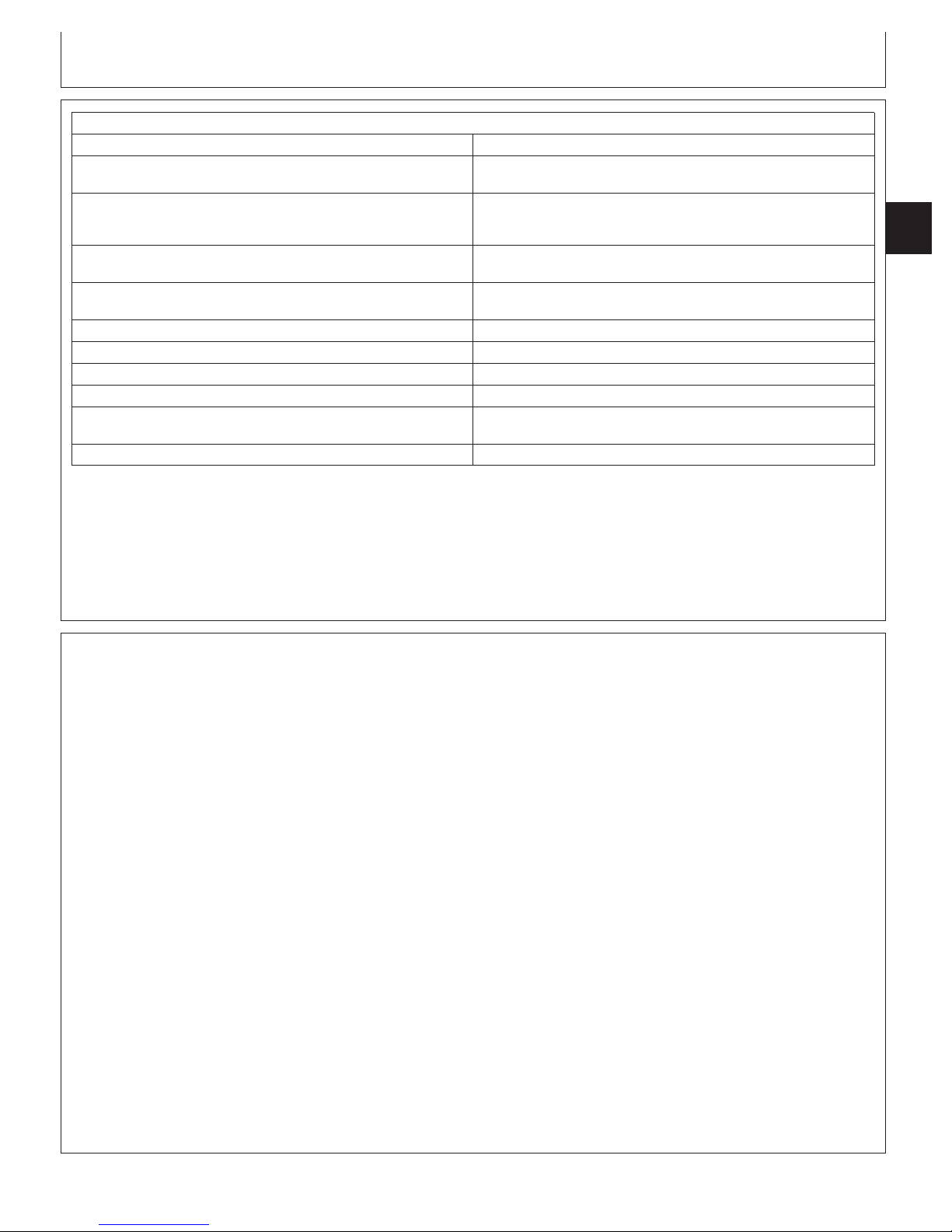
Engine Rebuild Guide, Break-In and Tune-Up
ENGINE ASSEMBLY SEQUENCE—CONTINUED
Procedure Reference
Install water manifold/thermostat housing assembly. See REMOVE AND INSTALL THERMOSTAT HOUSING in Group
070.
Install oil filter housing/oil cooler assembly. See INSTALL OIL COOLER/OIL FILTER VALVE HOUSING
ASSEMBLY OR OIL COOLER COVER/VALVE HOUSING
ASSEMBLY in Group 060.
Install exhaust manifold assembly. See REMOVE, INSPECT AND INSTALL EXHAUST MANIFOLD in
Group 080.
Install turbocharger. Connect all turbocharger oil lines and See INSTALL TURBOCHARGER in Group 080.
intake/exhaust piping.
Install alternator. See REMOVE AND INSTALL ALTERNATOR in Group 100.
Install compressor. See CTM67, OEM Engine Accessories.
Install fan drive, fan and fan belt. See Group 070.
Mount engine into vehicle. See vehicle repair manual.
Flush cooling system. Fill engine systems with recommended fuel, See FLUSH AND SERVICE COOLING SYSTEM in Section 01,
lubricant, and coolant. Group 002.
Perform engine break-in and normal standard performance checks. See PERFORM ENGINE BREAK-IN in this group.
02
010
15
Engine Break-In Guidelines
Engine break-in should be performed after overhaul or
when the following repairs have been made:
Main bearings, rod bearings, crankshaft, or any
combination of these parts have been replaced.
Pistons, rings, or liners have been replaced.
Rear crankshaft oil seal and wear sleeve have been
replaced. (Primary objective is to see if oil seal still leaks).
Cylinder head has been removed.
Electronic unit injectors have been removed or critical
adjustments have been made while they are on the
engine. (Primary objective of break-in is to check power).
RG,RG34710,52 –19–21AUG02–3/3
CTM100 (06APR04)
02-010-15
P
OWERTECH
RG,RG34710,1053 –19–05DEC00–1/1
10.5 L & 12.5 L Diesel Engines
040604
PN=63
Page 66

Perform Engine Break-In
Engine Rebuild Guide, Break-In and Tune-Up
IMPORTANT: If engine has a PTO, break-in can be
performed at the PTO if it is done as
02
010
16
specified below. To prevent possible
damage to the PTO gear box, DO
NOT apply full load through the PTO
for any longer than the specified 10
minutes below.
Use a dynamometer to perform the following
preliminary break-in procedure. If necessary,
preliminary engine break-in can be performed without
a dynamometer if under controlled operating
conditions.
IMPORTANT: DO NOT use John Deere PLUS-50 oil
or engine oils meeting API CG4, API
CF4, ACEA E3 or ACEA E2,
performance levels during break-in
period of an engine that has had a
major overhaul. These oils will not
allow an overhauled engine to
properly wear during the break-in
period.
Do not add makeup oil until the oil
level is BELOW the add mark. John
Deere Break-In Oil should be used to
make up any oil consumed during
break-in period.
DO NOT fill above the crosshatch
pattern or FULL mark. Oil levels
anywhere within the crosshatch are
acceptable.
1. Fill engine crankcase to proper level with John
Deere ENGINE BREAK-IN OIL during break-in
operation. Use break-in oil regardless of ambient
temperature. This oil is specifically formulated to
enhance break-in of John Deere diesel engines.
Under normal conditions, do not exceed 100 hours
with break-in oil.
If John Deere Engine Break-In Oil is not available,
use diesel engine oil meeting API Service
Classification CE or ACEA Specification E1.
IMPORTANT: During preliminary break-in,
periodically check engine oil
pressure and coolant temperature.
Also check for signs of fuel, oil, or
coolant leaks.
2. Start engine, run at loads and speeds shown in
following chart for time limits given.
PRELIMINARY ENGINE BREAK-IN AFTER MAJOR OVERHAUL
Time Load Engine Speed
1 minute No load 850 rpm
2 minutes No load Fast Idle
10 minutes 1/2—3/4 load 2000 rpm to rated
speed
10 Minutes Full load Rated speed
3. After preliminary break-in, run engine 1—2 minutes
at 1500 rpm, with no load before shut-down.
4. Check and readjust valve clearance as necessary.
Cylinder head retorque is not required.
NOTE: During the first 20 hours, avoid prolonged
periods of engine idling or sustained maximum
load operation. If engine will idle longer than 5
minutes, stop engine.
5. Operate the engine at heavy loads with minimal
idling during the break-in period.
If the engine has significant operating time at idle,
constant speeds, and/or light load usage, an additional
100 hour break-in period is recommended using a new
change of John Deere ENGINE BREAK-IN OIL and
new John Deere oil filter.
CTM100 (06APR04)
Continued on next page
02-010-16
P
OWERTECH
RG,100,JW7645 –19–05NOV99–1/2
10.5 L & 12.5 L Diesel Engines
040604
PN=64
Page 67

Engine Rebuild Guide, Break-In and Tune-Up
Check engine oil level more frequently during engine
break-in period. As a general rule, makeup oil should
not need to be added during 100-hour break-in period.
However, if makeup oil is required in the first 100-hour
break-in, an additional 100-hour break-in period is
required. Use a new change of John Deere ENGINE
BREAK-IN OIL and a new John Deere oil filter.
After 100 hours maximum, drain break-in oil and
change oil filter. Fill crankcase with John Deere
TORQ-GARD SUPREMEOR PLUS-50or other
TORQ-GARD SUPREME is a registered trademark of Deere &
Company.
PLUS-50 is a registered trademark of Deere & Company.
Check Crankcase Ventilation System
1. Inspect crankcase ventilation system for restrictions.
Lack of ventilation causes sludge to form in crankcase.
This can lead to clogging of oil passages, filters, and
screens, resulting in serious engine damage.
heavy-duty diesel engine oil within the same service
classification as recommended in this manual. See
DIESEL ENGINE OIL in Group 002, Fuels, Lubricants,
and Coolant.
NOTE: Some increase in oil consumption may be
expected when low viscosity oils are used.
Check oil levels more frequently.
If air temperature is below -10°C (14°F), use
an engine block heater.
RG,100,JW7645 –19–05NOV99–2/2
02
010
17
2. Clean crankcase vent tube (A) with solvent and
compressed air if restricted. Install and tighten hose
clamps securely.
A—Crankcase Vent Tube
Crankcase Vent Tube
RG10239 –UN–09JUL99
DPSG,OUO1004,919 –19–30JUN99–1/1
CTM100 (06APR04)
02-010-17
P
OWERTECH
10.5 L & 12.5 L Diesel Engines
040604
PN=65
Page 68

Engine Rebuild Guide, Break-In and Tune-Up
Check Air Intake System
1. Replace air cleaner primary filter element. Replace
secondary element if primary element has holes in it.
02
010
18
(See REPLACING AIR CLEANER FILTER ELEMENTS
in operator’s manual.)
2. Check condition of air intake hose(s). Replace hoses
that are cracked, split, or otherwise in poor condition.
3. Check hose clamps for tightness. Replace clamps that
cannot be properly tightened. This will help prevent
dust from entering the air intake system which could
cause serious engine damage.
4. If air cleaner has an automatic dust unloader valve (A),
inspect valve for dust buildup or restrictions.
5. Check air intake restriction indicator gauge (B) (if
equipped) to determine if air cleaner needs to be
serviced.
Unloader Valve
RG8717A –UN–12JUL99
A—Unloader Valve
B—Restriction Indicator Gauge
Check Exhaust System
1. Inspect exhaust system for leaks or restrictions. Check
manifold for cracks. Repair or replace as necessary.
2. Check that turbocharger-to-exhaust elbow adapter
clamps are securely tightened and do not leak.
3. Check exhaust stack for evidence of oil leakage past
valve stem seals.
Restriction Indicator Gauge
RG8719A –UN–12JUL99
DPSG,OUO1004,920 –19–09JUL99–1/1
Oil in exhaust stack may be caused by excessive valve
stem-to-guide clearance or excessive light load engine
idling.
CTM100 (06APR04)
02-010-18
P
OWERTECH
RG,RG34710,1057 –19–23OCT97–1/1
10.5 L & 12.5 L Diesel Engines
040604
PN=66
Page 69

Engine Rebuild Guide, Break-In and Tune-Up
Check and Service Cooling System
1. Remove trash that has accumulated on or near
radiator.
2. Visually inspect entire cooling system and all
components for leaks or damage. Repair or replace as
necessary.
3. Remove the foam filter from weep hole (A, shown
removed) located on the side of timing gear cover and
discard filter. Inspect the weep hole for any restrictions.
4. Insert a heavy gauge wire deep into weep hole to
make sure hole is open.
5. Install new foam filter flush with bore opening.
Weep Hole with Foam Filter
A—Weep Hole
Continued on next page
02
010
19
RG8718A –UN–12JUL99
DPSG,OUO1004,922 –19–01JUL99–1/2
CTM100 (06APR04)
02-010-19
P
OWERTECH
10.5 L & 12.5 L Diesel Engines
040604
PN=67
Page 70

Engine Rebuild Guide, Break-In and Tune-Up
CAUTION: Do not drain coolant until the coolant
temperature is below operating temperature.
Always loosen coolant drain valve (A) slowly to
relieve any excess pressure.
02
010
6. Remove and check thermostat(s). (See REMOVE AND
20
TEST THERMOSTATS in Group 025.)
7. Drain and flush cooling system. (See FLUSH AND
SERVICE COOLING SYSTEM in Group 002.)
IMPORTANT: Air must be expelled from cooling
system when system is refilled. Loosen
temperature sending unit fitting at rear
of cylinder head, bleed plug at top front
of cylinder head, or plug in thermostat
housing to allow air to escape when
filling system. Retighten fitting or plug
when all the air has been expelled.
8. Fill cooling system with coolant. Follow
recommendations in Group 002. (See DIESEL
ENGINE COOLANT RECOMMENDATIONS in Group
002.)
9. Run engine until it reaches operating temperature.
Check entire cooling system for leaks.
10. After engine cools, check coolant level.
NOTE: Coolant level should be even with bottom of
radiator filler neck.
11. Check system for holding pressure. (See PRESSURE
TEST COOLING SYSTEM AND RADIATOR CAP in
Section 04, Group 150.)
Service Cooling System Safely
TS281 –UN–23AUG88
RG8246 –UN–06DEC97
Coolant Drain Valve
A—Coolant Drain Valve
CTM100 (06APR04)
02-010-20
P
OWERTECH
DPSG,OUO1004,922 –19–01JUL99–2/2
10.5 L & 12.5 L Diesel Engines
040604
PN=68
Page 71

Check Electrical System
CAUTION: Battery gas can explode. Keep
sparks and flames away from batteries. Use a
flashlight to check battery electrolyte level.
Never check battery charge by placing a metal
object across the posts. Use a voltmeter or
hydrometer.
Engine Rebuild Guide, Break-In and Tune-Up
02
010
21
Always remove grounded (-) battery clamp first
and replace it last.
1. Clean batteries and cables with damp cloth. If
corrosion is present, remove it and wash terminals with
a solution of ammonia or baking soda in water. Then
flush area with clean water.
2. Coat battery terminals and connectors with petroleum
jelly mixed with baking soda to retard corrosion.
3. Test batteries. If batteries are not near full charge, try
to find out why.
4. On low-maintenance batteries, check level of
electrolyte in each cell of each battery. Level should be
to bottom of filler neck. If water is needed, use clean,
mineral-free water.
If water must be added to batteries more often than
every 250 hours, alternator may be overcharging.
NOTE: Water cannot be added to maintenance-free
batteries.
Prevent Battery Explosions
TS204 –UN–23AUG88
5. If batteries appear to be either undercharged or
overcharged, check alternator and charging circuit.
6. Check tension of drive belts. See operator’s manual.
7. Check operation of starter motor and gauges.
NOTE: For test and repair of alternators and starter
motors, see CTM77, Alternators and Starter
Motors.
CTM100 (06APR04)
02-010-21
P
OWERTECH
RG,RG34710,1059 –19–23OCT97–1/1
10.5 L & 12.5 L Diesel Engines
040604
PN=69
Page 72

Engine Rebuild Guide, Break-In and Tune-Up
Preliminary Engine Testing Before Tune-Up
Before tuning-up an engine, determine if a tune-up will
restore operating efficiency. If in doubt, the following
preliminary tests will help determine if the engine can be
02
tuned-up. Choose from the following procedures only
010
those necessary to restore the unit.
22
1. After engine has stopped for several hours, loosen
crankcase drain plug and watch for any water to seep
out. A few drops could be due to condensation, but
any more than this would indicate problems which
require engine repairs rather than just a tune-up.
2. With engine stopped, inspect engine coolant for oil film.
With engine running, inspect coolant for air bubbles.
Either condition would indicate problems which require
engine repairs rather than just a tune-up.
3. Perform a dynamometer test and record power output.
(See DYNAMOMETER TEST in Section 04, Group
150.) Repeat dynamometer test after tune-up.
Compare power output before and after tune-up.
CTM100 (06APR04)
02-010-22
P
OWERTECH
DPSG,OUO1004,921 –19–07NOV00–1/1
10.5 L & 12.5 L Diesel Engines
040604
PN=70
Page 73

Engine Rebuild Guide, Break-In and Tune-Up
General Tune-Up Recommendations
As a general rule, an engine tune-up is not necessary if
ALL recommended operator’s manual hourly service
procedures are performed on schedule. If your engine
performance is not within the rated application guidelines,
the following service procedures are recommended to
help restore engine to normal operating efficiency.
IMPORTANT: These engines are equipped with
electronically-controlled governors
which have a diagnostic feature that will
display detailed codes to alert operator
of specific performance problems. Refer
to CTM115 for Delphi/Lucas ECU
controls, and refer to CTM188 for later
John Deere ECU controls.
Operation Detailed Reference
Check for and correct any diagnostic trouble codes. ........................................................... CTM115 or CTM188
Change engine oil and filters. ............................................................................................... Operator’s Manual
Lubricate PTO clutch internal levers and linkage, if equipped. ............................................ Operator’s Manual
Replace fuel filter. ................................................................................................................. CTM115 or CTM188, Operator’s Manual
Clean crankcase vent tube. .................................................................................................. This Group/Operator’s Manual
Check air intake system. Replace air cleaner elements. ..................................................... This Group/Operator’s Manual
Check exhaust system. ......................................................................................................... This Group
Check and service engine cooling system. .......................................................................... This Group/Operator’s Manual
Check and adjust fan and alternator belts. ........................................................................... Operator’s Manual
Check electrical system. ....................................................................................................... This Group
Check crankshaft vibration damper. ..................................................................................... Group 040/Operator’s Manual
Inspect turbocharger and check turbocharger boost pressure. ............................................ Section 04, Group 150 of CTM115 or CTM188
Check fuel injection system: Check electronic unit injectors. ............................................... Section 04, Group 150 of CTM115 or CTM188
Check engine valve clearance and EUI preload. Adjust if necessary. ................................. Section 02, Group 020 of CTM115 or CTM188
Check engine oil pressure. Correct as necessary. ............................................................... Section 04, Group 150
Check engine speeds. Correct as necessary. ...................................................................... Authorized Servicing Dealer
Check engine performance on dynamometer. ...................................................................... Section 04, Group 150
02
010
23
CTM100 (06APR04)
02-010-23
P
OWERTECH
DPSG,OUO1004,923 –19–30AUG02–1/1
10.5 L & 12.5 L Diesel Engines
040604
PN=71
Page 74

02
010
24
Engine Rebuild Guide, Break-In and Tune-Up
CTM100 (06APR04)
02-010-24
P
OWERTECH
10.5 L & 12.5 L Diesel Engines
040604
PN=72
Page 75

Remove and Install Rocker Arm Cover
Remove Rocker Arm Cover
Group 020
Cylinder Head and Valves
1. Remove air intake cross-over tube (shown removed).
NOTE: Turbocharger is removed for photographic
purposes only. It is not necessary to remove
turbocharger for rocker arm cover removal.
2. Remove center hold-down cap screw with isolator.
3. Remove two outside cap screws with isolators (A), and
thread cap screws into rocker arm cover as shown.
NOTE: Rocker arm cover gasket is reusable if no visible
damage is detected. Do not store cover resting on
gasket surface.
4. Lift rocker arm cover off engine.
Install Rocker Arm Cover
IMPORTANT: Always check routing of unit injector
wiring (B) before installing rocker arm
cover. Wiring should be positioned so
that rocker arms never contact wire.
1. Inspect rocker arm cover gasket to ensure that gasket
is properly seated in groove and that contact face is
clean.
02
020
1
RG8173 –UN–05DEC97
Isolators
RG8818 –UN–11DEC97
Unit Injector Wiring
A—Isolators
B—Unit Injector Wiring
2. Position rocker arm cover onto two locating dowels in
cylinder head.
3. Install center hold-down cap screw with isolator.
Tighten to specifications.
Rocker Arm Cover Hold-Down
Cap Screws1—Torque 30 N•m (22 lb-ft).....................................................
Specification
4. Install two outside hold-down cap screws with isolators.
Tighten to specifications.
1
Tighten center cap screw first, then tighten sides.
CTM100 (06APR04)
Continued on next page
02-020-1
P
OWERTECH
RG,RG34710,60 –19–03NOV99–1/2
10.5 L & 12.5 L Diesel Engines
040604
PN=73
Page 76

Cylinder Head and Valves
Rocker Arm Cover Hold-Down
Cap Screws1—Torque 30 N•m (22 lb-ft).....................................................
Specification
5. Install air intake cross-over tube and tighten
02
020
connections securely.
2
1
Tighten center cap screw first, then tighten sides.
Clean and Inspect Crankcase Ventilation
Assembly
1. Remove ventilation outlet tube from rocker arm cover
(shown removed).
NOTE: Ventilator assembly-to-rocker cover self-tapping
cap screws have been replaced by flange head
cap screws with pre-applied sealant. Discard old
self-tapping cap screws and replace with new cap
screws.
2. Remove two cap screws securing ventilator assembly
(B) to cover and remove.
3. Clean ventilator assembly in solvent and dry with
compressed air.
RG,RG34710,60 –19–03NOV99–2/2
RG10242 –UN–20JUL99
Crankcase Ventilation Assembly
A—O-Rings
B—Ventilator Assembly
4. Install ventilator assembly in reverse order of removal.
Replace O-rings (A) as necessary.
5. Tighten ventilator assembly-to-rocker arm cover cap
screws to specifications.
Specification
Crankcase Vent Baffle-to-Rocker
Arm Cover Cap Screws—Torque 15 N•m (11 lb-ft) (133 lb-in.).................
6. Install ventilator outlet tube onto elbow attached to
rocker arm cover.
CTM100 (06APR04)
02-020-2
P
OWERTECH
RG,RG34710,61 –19–03SEP02–1/1
10.5 L & 12.5 L Diesel Engines
040604
PN=74
Page 77

Cylinder Head and Valves
Replace Rocker Arm Cover Gasket
1. Remove rocker arm cover. (See REMOVE AND
INSTALL ROCKER ARM COVER earlier in this group.)
2. Remove existing gasket from cover and discard. Clean
gasket groove as needed.
3. Position new gasket at two front corners of cover with
double lips (A) of gasket facing up.
IMPORTANT: DO NOT stretch gasket while seating in
groove of cover.
4. Seat gasket on front side of cover and proceed around
entire cover gasket groove using a deep-well socket.
5. Re-seat gasket again (especially in corners) after entire
gasket is installed in groove.
A—Gasket Double Lips
02
020
3
RG8784 –UN–10DEC97
Replacing Rocker Arm Cover Gasket
RG,RG34710,62 –19–30SEP97–1/1
CTM100 (06APR04)
02-020-3
P
OWERTECH
10.5 L & 12.5 L Diesel Engines
040604
PN=75
Page 78

Cylinder Head and Valves
Check and Adjust Valve Assembly
Clearances and Injector Preload
Rocker arm assembly adjustments consist of intake and
exhaust valve clearance (lash) and electronic unit injector
02
preload adjustment.
020
4
CAUTION: To prevent accidental starting of
engine while performing rocker arm adjustment,
ALWAYS disconnect NEGATIVE (–) battery
terminal.
IMPORTANT: All rocker arm assembly adjustments
MUST BE performed with engine COLD.
1. Remove rocker arm cover. (See REMOVE AND
INSTALL ROCKER ARM COVER earlier in this group.)
2. Remove plug from cylinder block and install JDG820
Flywheel Turning Tool (B).
3. Remove threaded plug from timing hole below oil
cooler and filter housing assembly.
IMPORTANT: Timing pin MUST BE installed in slot of
camshaft first, then install second
timing pin in crankshaft slot by
carefully rocking flywheel back and
forth.
4. Rotate engine flywheel in running direction
(counterclockwise as viewed from rear) until JDG971
Timing Pin (A) engages single timing slot (D) in
camshaft. The proper timing slot can be found by
viewing camshaft timing lobe through camshaft timing
pin bore while rotating engine. The double timing slot
(E) will be at approximately 11 o’clock (viewed from
rear of engine) when pin is installed in slot (D).This
ensures that engine is locked at TDC of No. 1
cylinder’s compression stroke. Intake and exhaust
rocker arms on No. 1 cylinder should be loose.
A—JDG971 Timing Pin
B—JDG820 Flywheel Turning Tool
C—JDG971 Timing Pin
D—Single Timing Slot
E—Double Timing Slot
JDG971 Timing Pin in Camshaft
RG8228A –UN–05DEC97
RG8227D –UN–05DEC97
JDG971 Timing Pin in Crankshaft
CTM100 (06APR04)
Continued on next page
02-020-4
Camshaft Timing Slot
P
OWERTECH
RG11165 –UN–30OCT00
RG,RG34710,63 –19–16OCT00–1/6
10.5 L & 12.5 L Diesel Engines
040604
PN=76
Page 79

Cylinder Head and Valves
IMPORTANT: DO NOT insert timing pin full depth into
cylinder block crankshaft timing hole
when rotating engine flywheel until
double slot on camshaft timing lobe is
at approximately 11 o’clock (viewed
from rear of engine) to avoid crankshaft
counterweight bending timing pin.
5. Slightly move engine flywheel back and forth with
turning tool until a second JDG971 Timing Pin (C) can
be installed in slot in crankshaft. This ensures that
camshaft and crankshaft are in sync (properly timed).
If timing pin does not enter crankshaft timing slot,
crankshaft is not properly timed with camshaft.
Crankshaft MUST BE timed to camshaft. (See CHECK
AND ADJUST CAMSHAFT-TO-CRANKSHAFT TIMING
in Group 050.)
02
020
5
Continued on next page
RG,RG34710,63 –19–16OCT00–2/6
CTM100 (06APR04)
02-020-5
P
OWERTECH
10.5 L & 12.5 L Diesel Engines
040604
PN=77
Page 80

02
020
Cylinder Head and Valves
6
Rocker Arm Assembly Identification
6. Check and adjust (as needed) valve stem-to-bridge
clearance (lash) on intake valves Nos. 1, 2, and 4, and
exhaust valves Nos. 1, 3, and 5 (shaded locations).
Adjust preload on electronic unit injectors Nos. 3, 5,
and 6 (shaded locations).
Valve clearance is adjusted using JDG1333 Feeler
Gauge Set or equivalent 1/4 inch (6.0 mm) wide
automotive ignition point-type feeler gauge installed at
the joint between the valve bridge and valve stem tip
(B) that is near the exhaust (right) side of engine.
Loosen lock nuts, set clearance with adjusting screw
and tighten lock nut to specified torque while holding
adjusting screw stationary.
Valve Stem-to-Bridge Clearance (Engine Cold)—Specification
Intake Valve—Clearance 0.58 ± 0.05 mm (0.023 ± 0.002
Exhaust Valve—Clearance 1.08 ± 0.05 mm (0.043 ± 0.002
..........................
in.)
.......................
in.)
7. Tighten intake and exhaust valve adjusting screw lock
nuts to specifications.
RG8773 –UN–19MAY98
RG8232 –UN–05DEC97
Adjusting Valve Lash/Clearance
B—Valve Stem Tip
Intake and Exhaust Valve
Specification
Adjusting Screw Lock Nuts—
Torque 50 N•m (37 lb-ft).............................................................................
CTM100 (06APR04)
Continued on next page
02-020-6
P
OWERTECH
RG,RG34710,63 –19–16OCT00–3/6
10.5 L & 12.5 L Diesel Engines
040604
PN=78
Page 81

Cylinder Head and Valves
8. Set electronic unit injector preload by turning the EUI
rocker arm adjusting screw in until there is zero
clearance between the rocker arm roller and camshaft
lobe. Next, turn the adjusting screw in an additional
one-half turn (180°). Hold adjusting screw stationary
while tightening lock nut to specified torque. Tighten
EUI adjusting screw lock nuts to specifications.
02
020
7
Electronic Unit Injector—Preload 0.00 mm (in.) clearance plus 1/2
Electronic Unit Injector Adjusting
Screw Lock Nuts—Torque 65 N•m (48 lb-ft)..............................................
Specification
...........
turn in (180°)
Continued on next page
RG,RG34710,63 –19–16OCT00–4/6
CTM100 (06APR04)
02-020-7
P
OWERTECH
10.5 L & 12.5 L Diesel Engines
040604
PN=79
Page 82

02
020
Cylinder Head and Valves
8
Rocker Arm Assembly Identification
9. Reference mark flywheel (A) as shown with engine
locked at No.1 TDC compression stroke.
IMPORTANT: DO NOT insert timing pin full depth into
cylinder block when rotating engine
flywheel until reference mark is within a
few degrees of a full crankshaft
revolution to eliminate possibility of
crankshaft counterweight bending
timing pin.
10. Remove both timing pins and rotate engine flywheel
one full revolution (360°) until timing pin (B) enters
slot in crankshaft again. Engine will now be locked at
No. 6 TDC compression stroke.
11. Check and adjust, as needed, valve clearance (lash)
on intake valves Nos. 3, 5, and 6 and exhaust valves
Nos. 2, 4, and 6 (shaded locations). Adjust preload
on injectors Nos. 1, 2, and 4 (shaded locations).
12. Tighten intake and exhaust valve adjusting screw lock
nuts to specifications.
RG8774 –UN–19MAY98
RG8229 –UN–05DEC97
Locking Engine at No.6 TDC
A—Flywheel Reference Mark
B—Timing Pin
Intake and Exhaust Valve
Specification
Adjusting Screw Lock Nuts—
Torque 50 N•m (37 lb-ft).............................................................................
Tighten EUI adjusting screw lock nuts to specifications.
Specification
Electronic Unit Injector Adjusting
Screw Lock Nuts—Torque 65 N•m (48 lb-ft)..............................................
CTM100 (06APR04)
Continued on next page
02-020-8
P
OWERTECH
RG,RG34710,63 –19–16OCT00–5/6
10.5 L & 12.5 L Diesel Engines
040604
PN=80
Page 83

Cylinder Head and Valves
IMPORTANT: Thoroughly inspect ALL intake and
exhaust valve bridges (A) for proper
seating on valve stems (B) from both
sides of engine. Also, be sure that push
tubes (C) are properly seated in top of
valve bridge.
Use a flashlight and carefully check
each bridge (for proper seating on valve
stems) from both sides of the engine,
by lifting up on each bridge to verify
proper seating. VALVE BRIDGES THAT
ARE NOT PROPERLY SEATED ON
VALVE STEMS WILL RESULT IN
MAJOR ENGINE VALVE TRAIN
FAILURE.
02
020
9
13. Check that all intake rocker arm adjusting screws (D)
have approximately the same number of threads
visible above lock nut. Normally flush to maximum of
two threads.
If the number of threads above lock nut at any
location is visually different, verify bridge seating and
readjust valve clearance to ensure everything is within
specification at this location.
14. Install plug in timing pin hole below oil cooler and
tighten to specifications.
Specification
Timing Pin Plug (Below Oil
Cooler)—Torque 33 N•m (24 lb-ft)..............................................................
Inspect Valves
RG9743 –UN–04DEC98
RG9626A –UN–04DEC98
Adjusting Screws
A—Valve Bridges
B—Valve Stems
C—Push Tubes
D—Adjusting Screws
RG,RG34710,63 –19–16OCT00–6/6
CTM100 (06APR04)
02-020-9
P
OWERTECH
10.5 L & 12.5 L Diesel Engines
040604
PN=81
Page 84

Remove Rocker Arm Assembly
CAUTION: After operating engine, allow exhaust
system to cool before servicing engine.
02
020
1. Remove rocker arm cover.
10
2. Lock camshaft and crankshaft at TDC of No.1
cylinder’s compression stroke.
Cylinder Head and Valves
3. Remove electronic unit injector wiring harness from
rocker arm shaft clamps.
IMPORTANT: ALWAYS loosen all intake, exhaust and
EUI rocker arm adjusting screws before
removal or installation of rocker arm
assembly to relieve pressure. This
allows for a more uniform rocker arm
cap screw clamp load and reduces the
possibility of damage to valve train
components.
Remove push tubes and valve bridges
immediately after relieving rocker arm
pressure. Push tubes can fall into oil
drain opening of cylinder head causing
oil pan removal to retrieve tubes.
4. Loosen EUI, intake, and exhaust valve rocker arm
adjusting screw lock nut and relieve pressure at all
locations.
5. Remove push tubes (C) and valve bridges (D) from all
valve stems.
Removing Valve Bridge and Push Tubes
RG8262B –UN–06DEC97
RG8459A –UN–21JUL99
Removing Rocker Arm Assembly with JDG970A
A—Rocker Arm Shaft Oil Tubes (Dual Rail Fuel
System Only)
B—Rocker Arm Lifting Fixture
C—Push Tubes
D—Valve Bridges
6. Remove two rocker arm shaft oil tubes (A) (dual rail
system only). Remove rocker arm shaft hold-down
clamps.
IMPORTANT: Rocker arm shaft hold-down clamp cap
screws can not be reused. Use new cap
screws for reassembly.
7. Install shaft clamp cap screw in end hole of each
rocker arm shaft so that rocker arms do not slide off
shaft when lifted.
CTM100 (06APR04)
Continued on next page
02-020-10
P
OWERTECH
RG,RG34710,64 –19–21DEC00–1/2
10.5 L & 12.5 L Diesel Engines
040604
PN=82
Page 85

Cylinder Head and Valves
CAUTION: A second set of pins has been added
to JDG970A tool. With 6125 Tier II engines
(engine serial no. 030000—), the holes for the
pins in the rocker arm shaft are smaller. The
new pins have a smaller diameter shaft and are
marked “JDG1847”. To safely handle the rocker
arm shaft assembly, BE CERTAIN to verify the
engine serial number, then use the correct pins
for that engine.
8. Depress actuator (ball) pins and install JDG970A
Rocker Arm Lifting Fixture (B) into rocker arm shaft
cap screw holes as shown. Replace pins to seat ball
locks.
9. Remove both front and rear rocker arm and shaft
assemblies using JDG970A Rocker Arm Lifting Fixture.
10. Discard rocker arm shaft hold-down clamp cap
screws.
02
020
11
RG,RG34710,64 –19–21DEC00–2/2
CTM100 (06APR04)
02-020-11
P
OWERTECH
10.5 L & 12.5 L Diesel Engines
040604
PN=83
Page 86

Remove Cylinder Head
On some applications, it may be necessary to remove
engine from machine to service cylinder head. Refer to
your Machine Technical Manual for engine removal
02
procedure.
020
12
CAUTION: After operating engine, allow exhaust
system to cool before servicing engine.
Cylinder Head and Valves
DO NOT drain coolant until the coolant is below
operating temperature. Only remove radiator
filler cap when cool enough to touch with bare
hands. Slowly loosen cap to first stop to relieve
pressure before removing completely.
1. Drain all oil and coolant.
2. Remove intake manifold (6105H and 6125H engines).
(See REMOVE, INSPECT AND INSTALL INTAKE
MANIFOLD in Group 080.)
3. Remove turbocharger (A). (See REMOVE
TURBOCHARGER in Group 080.)
4. Remove exhaust manifold (B). (See REMOVE,
INSPECT AND INSTALL EXHAUST MANIFOLD in
Group 080.)
5. On 6105A and 6125A engines, remove aftercooler
assembly. (See REMOVE AND INSTALL
AFTERCOOLER ASSEMBLY in Group 080.)
6. Remove thermostat housing/water manifold (C). (See
REMOVE AND INSTALL THERMOSTAT HOUSING in
Group 070.)
Removing Turbocharger and Exhaust Manifold
RG8187A –UN–05DEC97
A—Turbocharger
B—Exhaust Manifold
C—Thermostat Housing/Water Manifold
7. Remove rocker arm assembly. (See REMOVE AND
INSTALL ROCKER ARM ASSEMBLY, earlier in this
group).
8. Remove electronic unit injectors and wiring harness.
Refer to the appropriate fuel system repair manual.
Delphi/Lucas ECU controlled fuel systems:
CTM100 (06APR04)
Continued on next page
02-020-12
P
OWERTECH
RG,RG34710,65 –19–13AUG99–1/5
10.5 L & 12.5 L Diesel Engines
040604
PN=84
Page 87

Cylinder Head and Valves
• See REMOVE AND INSTALL ELECTRONIC UNIT
INJECTORS in CTM115, Section 02, Group 090.
John Deere Level 6 ECU controlled fuel systems:
• See REMOVE AND INSTALL ELECTRONIC UNIT
INJECTORS in CTM188, Section 02, Group 090
(dual rail fuel systems).
• See REMOVE AND INSTALL ELECTRONIC UNIT
INJECTORS in CTM188, Section 02, Group 091
(single rail fuel systems).
9. Remove fan drive hub and camshaft gear access
cover.
Continued on next page
02
020
13
RG,RG34710,65 –19–13AUG99–2/5
CTM100 (06APR04)
02-020-13
P
OWERTECH
10.5 L & 12.5 L Diesel Engines
040604
PN=85
Page 88

Cylinder Head and Valves
10. Remove six cap screws securing camshaft gear
retaining washer (A) and remove camshaft gear (B).
NOTE: Later engines: 10.5 L S.N. (003764— ) and 12.5 L
02
020
14
S.N. (010967— ) with single rail fuel systems do
not have a fuel manifold. Return fuel line is
connected to port of single rail in back of cylinder
head. Inlet line and port are on left side of head
up by No.1 cylinder.
11. Remove fuel manifold block (C) on engines with dual
rail systems, or disconnect fuel inlet and return lines
on single rail systems. Refer to the appropriate fuel
system repair manual.
Delphi/Lucas ECU controlled fuel systems:
• See REMOVE AND INSTALL FUEL MANIFOLD in
CTM115, Section 02, Group 090.
John Deere Level 6 ECU controlled fuel systems:
Removing Camshaft Gear
RG8251A –UN–06DEC97
• See REMOVE AND INSTALL FUEL MANIFOLD in
CTM188, Section 02, Group 090.
12. Remove fuel supply pump. Refer to the appropriate
fuel system repair manual.
Delphi/Lucas ECU controlled fuel systems:
• See REMOVE AND INSTALL FUEL SUPPLY
PUMP in CTM115, Section 02, Group 090.
John Deere Level 6 ECU controlled fuel systems:
• See REMOVE AND INSTALL FUEL SUPPLY
PUMP in CTM188, Section 02, Group 090 (dual rail
fuel systems).
• See REMOVE AND INSTALL FUEL SUPPLY
PUMP in CTM188, Section 02, Group 091 (single
rail fuel systems).
Removing Supply Pump and Fuel Manifold (Early Engine
RG8264B –UN–06DEC97
Shown)
RG8544B –UN–10DEC97
DFRG4 Camshaft Locking Tool
A—Gear Retaining Washer
B—Camshaft Gear
C—Fuel Manifold
D—Fuel Supply Pump
E—DFRG4 Camshaft Locking Tool
CTM100 (06APR04)
Continued on next page
02-020-14
P
OWERTECH
RG,RG34710,65 –19–13AUG99–3/5
10.5 L & 12.5 L Diesel Engines
040604
PN=86
Page 89

Cylinder Head and Valves
NOTE: Cylinder head can be removed without removing
camshaft.
IMPORTANT: If cylinder head is removed with
camshaft installed, secure camshaft in
bushings with DFRG4 Camshaft
Locking Tool (E) so that camshaft
journals and bushings are not damaged
by camshaft sliding out of bushings.
(See DFRG4-CAMSHAFT LOCKING
TOOL in Section 05, Group 190 for
details on this dealer fabricated tool.)
Camshaft position sensor MUST BE
removed from air intake side of cylinder
head when removing or installing
camshaft to prevent camshaft binding
on sensor.
13. Remove camshaft front thrust ring. Remove camshaft
position sensor and remove camshaft if desired (see
REMOVE AND INSTALL CAMSHAFT in Group 050).
02
020
15
Continued on next page
RG,RG34710,65 –19–13AUG99–4/5
CTM100 (06APR04)
02-020-15
P
OWERTECH
10.5 L & 12.5 L Diesel Engines
040604
PN=87
Page 90

Cylinder Head and Valves
NOTE: If removing head with camshaft installed,
camshaft will have to be rotated to remove two of
the cylinder head cap screws.
14. Remove 26 cylinder head cap screws with washers
02
020
16
and discard.
IMPORTANT: DO NOT use screwdrivers or prybars
between cylinder block and head to
loosen gasket seal. Screwdrivers and
prybars can damage head and block
gasket surfaces.
15. Carefully lift cylinder head from block using an
overhead hoist or floor crane. Place head on a clean,
flat surface.
16. Remove cylinder head gasket. Inspect gasket for any
manufacturing imperfections. Inspect head, gasket,
and check for possible oil, coolant, or combustion
chamber leakage.
Removing Cylinder Head
RG8285 –UN–21MAY98
NOTE: DO NOT rotate engine crankshaft with cylinder
head removed unless all cylinder liners are
secured with cap screws and large, flat washers.
(See REMOVE PISTONS AND CONNECTING
RODS in Group 030.)
RG,RG34710,65 –19–13AUG99–5/5
CTM100 (06APR04)
02-020-16
P
OWERTECH
10.5 L & 12.5 L Diesel Engines
040604
PN=88
Page 91

Cylinder Head and Valves
Diagnosing Head Gasket Joint Failures
Head gasket failures generally fall into three categories:
• Combustion seal leakage.
• Coolant seal leakage.
• Oil seal leakage.
Combustion seal leakage failures occur when combustion
gases escape between cylinder head and head gasket
combustion flange, or between combustion flange and
cylinder liner. Leaking combustion gases may vent to an
adjacent cylinder, to a coolant or oil passage, or
externally.
Coolant or oil seal failures occur when oil or coolant
escapes between cylinder head and gasket body, or
between cylinder block and gasket body. The oil or
coolant may leak to an adjacent coolant or oil passage, or
externally.
Follow these diagnostic procedures when a head gasket
joint failure occurs or is suspected:
1. Before starting or disassembling engine, conduct a
visual inspection of machine, and note any of the
following:
• Oil or coolant in head gasket seam, or on adjacent
surfaces, especially right rear corner of gasket joint.
• Displacement of gasket from normal position.
• Discoloration or soot from combustion gas leakage.
• Leaking radiator, overflow tank, or hoses.
• Leaking coolant from coolant pump weep hole.
• Damaged or incorrect radiator, fan, or shroud.
• Obstructed air flow or coolant flow.
• Worn or slipping belts.
• Damaged or incorrect pressure cap.
• Presence of oil in coolant.
• Low coolant levels or improper coolant.
• Unusually high or low oil levels.
• Oil degradation, dilution, or contamination.
• Correctly specified electronic unit injectors.
• Indications of fuel delivery or gear train not properly
timed.
• Unburned fuel or coolant in exhaust system.
A
Cylinder Head Gasket Sealing Area
A—Combustion Sealing Areas
B—Coolant Sealing Areas
C—Cylinder Head Cap Screws
B
C
02
020
17
RG8430 –UN–22MAY98
CTM100 (06APR04)
Continued on next page
02-020-17
P
OWERTECH
RG,RG34710,69 –19–01NOV00–1/2
10.5 L & 12.5 L Diesel Engines
040604
PN=89
Page 92

Cylinder Head and Valves
2. Obtain coolant and oil samples for further analysis.
3. Start and warm up engine if it can be safely operated.
Examine all potential leakage areas again as outlined
02
020
18
previously. Using appropriate test and measurement
equipment, check for the following:
• White smoke, excessive raw fuel, or moisture in
exhaust system.
• Rough, irregular exhaust sound, or misfiring.
• Air bubbles, gas entrainment in radiator or overflow
tank.
• Loss of coolant from overflow.
• Excessive cooling system pressure.
• Coolant overheating.
• Low coolant flow.
• Loss of cab heating (air lock).
4. Shut engine down. Recheck crankcase, radiator, and
overflow tank for any significant differences in fluid
levels, viscosity, or appearance.
5. Compare your observations from above steps with the
appropriate diagnostic procedures in Section 04, Group
150. If diagnostic evaluations and observations provide
conclusive evidence of combustion gas, coolant, or oil
leakage from head gasket joint, the cylinder head must
be removed for inspection and repair of gasket joint
components.
RG,RG34710,69 –19–01NOV00–2/2
CTM100 (06APR04)
02-020-18
P
OWERTECH
10.5 L & 12.5 L Diesel Engines
040604
PN=90
Page 93
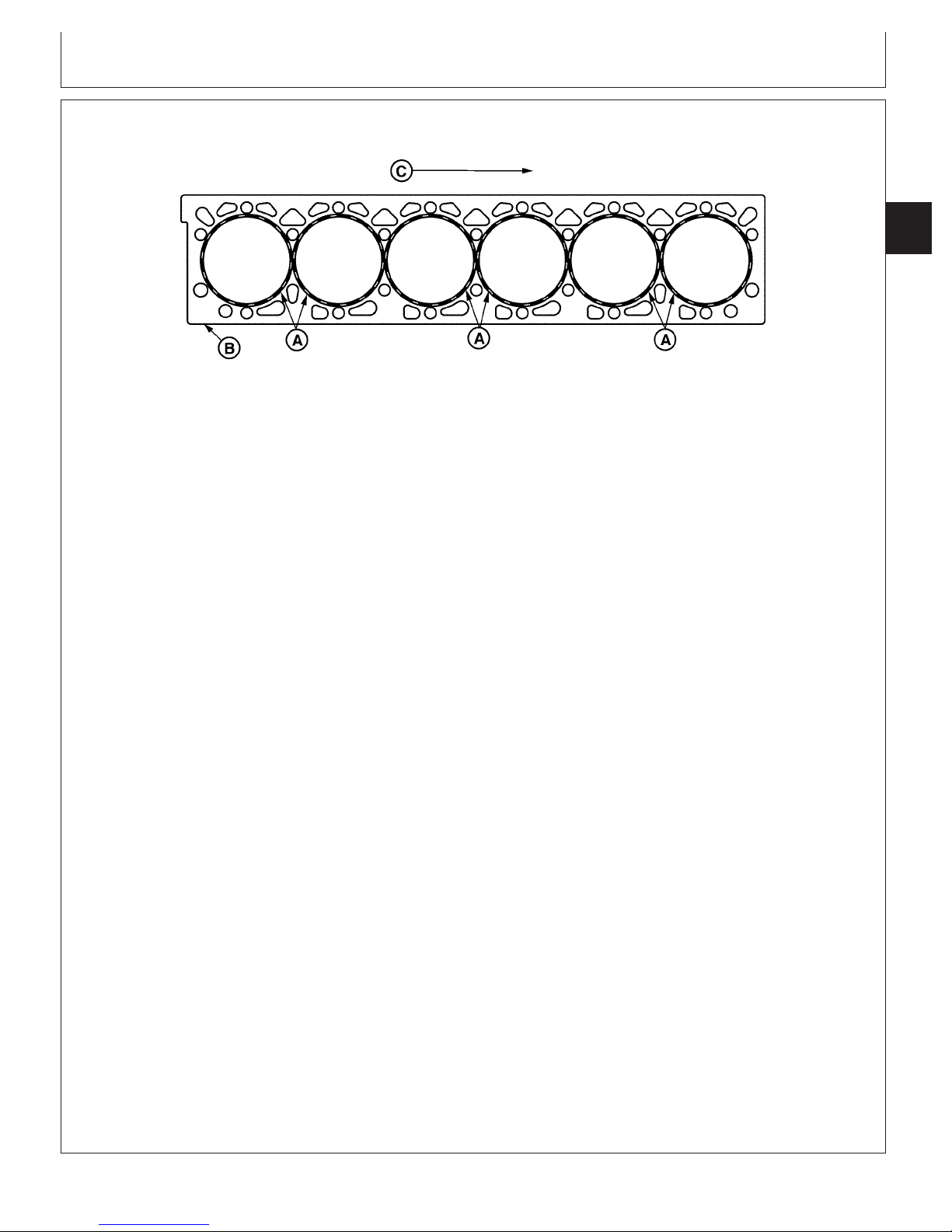
Cylinder Head and Valves
Head Gasket Inspection and Repair Sequence
02
020
19
Cylinder Head Gasket Inspection
A—Combustion Seals B—Gasket Body C—Front of Engine
(Flanges)
The following inspection procedures are recommended
whenever a head gasket joint failure occurs or when
joint disassembly takes place.
1. Review historical data relating to machine
operation, maintenance and repair, along with
diagnostic observations. Note all areas requiring
further inspection and analysis.
2. Remove rocker arm cover and check for presence
of coolant in the oil.
3. Record head cap screw torques prior to removal.
Upon removal, check cap screw length differences.
4. Remove cylinder head using appropriate lifting
devices to prevent handling damage to head
gasket. (See REMOVE CYLINDER HEAD in this
group.)
RG8429 –UN–19MAY98
Examine gasket body (B) for the following:
• Combustion gas erosion paths or soot deposits
originating at combustion seals.
• Extreme discoloration/hardening/embrittlement in
localized areas.
• Oil or coolant paths from port areas.
• Localized areas of low compression.
6. Before cleaning components, inspect head, block,
and liners for evidence of combustion gas and fluid
leakage. Inspect cylinders and valve ports for
unusual deposits.
7. Clean cylinder block. (See INSPECT AND CLEAN
CYLINDER BLOCK in Group 030.) Clean cylinder
head. (See CLEAN AND INSPECT CYLINDER
HEAD in this group.) Clean liners. (See CLEAN
CYLINDER LINERS in Group 030.)
5. Observe surfaces of removed head gasket.
Examine combustion seals (A) for the following:
• Flange severed/expanded/cracked/deformed.
• Adjacent body area burned/eroded.
• Fire ring severed/displaced/missing.
• Flange sealing pattern eccentric/contains voids.
• Discoloration of flange and adjacent body areas.
• Flange surfaces rough/abraided/channelled.
CTM100 (06APR04)
8. Proceed with the following dimensional checks and
Continued on next page
02-020-19
visual inspections:
• Cylinder Head (this group)
– Check surface flatness/finish.
– Inspect for surface damage.
– Check cylinder head thickness, if resurfacing.
• Cylinder Block and Liners (assembled and
clamped) (Group 030)
RG,RG34710,70 –19–30SEP97–1/2
P
OWERTECH
10.5 L & 12.5 L Diesel Engines
040604
PN=91
Page 94

Cylinder Head and Valves
02
020
20
– Check liner standout at four places on each
liner.
– Check liner standout difference between
cylinders.
• Cylinder Block (Group 030)
– Check surface flatness/finish.
– Inspect for surface damage.
– Check liner counterbore depth (if liner is
removed).
– Check top deck to crankshaft centerline
dimension.
– Inspect cap screw bosses; must be
clean/intact.
• Cylinder Liner (Group 030)
– Check liner flange flatness/finish.
– Check liner flange thickness (if liner is
removed).
– Inspect flange for damage.
• Cylinder Head Cap Screws (this group)
– Inspect condition of threads.
– Check length.
9. When inspections and measurements have been
completed, determine most probable causes of joint
failure. Make all necessary repairs to joint
components, cooling system, and fuel injection
system.
10. Reassemble the engine according to procedures
and specifications in the appropriate repair groups
of this manual.
RG,RG34710,70 –19–30SEP97–2/2
CTM100 (06APR04)
02-020-20
P
OWERTECH
10.5 L & 12.5 L Diesel Engines
040604
PN=92
Page 95

Cylinder Head and Valves
Disassemble and Inspect Rocker Arms and
Shaft Assembly
1. Remove rocker arms from shaft and identify for
installation in same position as removed.
2. Inspect rocker arm shaft for scoring and excess wear
at rocker arm contact points. Roll on a flat surface and
check for bends or distortion.
02
020
21
3. Check rocker arm adjusting screws and lock nuts for
thread damage.
4. Check valve bridges and push tubes for contact wear.
5. Clean all parts with clean solvent. Dry with compressed
air.
6. Measure rocker arm shaft OD and rocker arm bushing
ID. Compare measurements with specifications below.
7. Inspect rocker arm roller for uneven wear. Measure
roller OD and compare with specifications below.
Rocker Arm Bushing—ID 38.064 ± 0.013 mm (1.4986 ±
Rocker Arm Shaft—OD 38.000 ± 0.013 mm (1.4961 ±
Rocker Arm Shaft-to-Bushing—
Oil Clearance 0.064 ± 0.026 mm (0.0025 ±
Rocker Arm Shaft Intake and
Exhaust Roller—OD 39.995—40.045 mm
Rocker Arm Shaft Unit Injector
Roller—OD 37.995—38.045 mm
................................................
..................................................
................................................................
Specification
...........................
0.0005 in.)
..............................
0.0005 in.)
0.0010 in.)
(1.5746—1.5766 in.)
(1.4959—1.4978 in.)
Measure Rocker Arm Shaft
RG8395 –UN–21MAY98
RG8392 –UN–21MAY98
Measure Rocker Arm Bushing
Replace parts as necessary.
CTM100 (06APR04)
02-020-21
Measure Rocker Arm Roller
RG,RG34710,71 –19–30SEP97–1/1
P
OWERTECH
10.5 L & 12.5 L Diesel Engines
RG8390 –UN–21MAY98
040604
PN=93
Page 96

Cylinder Head and Valves
Preliminary Cylinder Head and Valve Checks
Make preliminary inspection of cylinder head and valve
assembly during disassembly.
02
Look for the following conditions:
020
22
Sticking Valves:
• Carbon deposits on valve stem.
• Worn valve guides.
• Scored valve stems.
• Warped valve stems.
• Misaligned or broken valve springs.
• Worn or distorted valve seats.
• Insufficient lubrication.
Warped, Worn, or Distorted Valve Guides:
• Lack of lubrication.
• Cylinder head distortion.
• Excessive heat.
• Unevenly tightened cylinder head cap screws.
Distorted Cylinder Head and Gasket Leakage:
• Loss of cylinder head cap screw torque.
• Broken cylinder head cap screw.
• Overheating from low coolant level operation.
• Insufficient liner standout.
• Coolant leakage into cylinder causing hydraulic
failure of gasket.
• Leaking aftercooler.
• Cracked cylinder head.
• Cracked cylinder liner.
• Damaged or incorrect gasket.
• Overpowering or overfueling.
• Damaged cylinder head or block surfaces.
• Improper surface finish on cylinder head.
• Improperly tightened cylinder head cap screws or
faulty gasket installation (misaligned).
Worn or Broken Valve Seats:
• Distorted cylinder head.
• Carbon deposits on seats due to incomplete
combustion.
• Valve spring tension too weak.
• Excessive heat.
• Improper valve clearance.
• Improper valve timing.
• Incorrect valve or seat installed.
Burned, Pitted, Worn, or Broken Valves:
• Worn or distorted valve seats.
• Loose valve seats.
• Worn valve guides.
• Insufficient cooling.
• Cocked or broken valve springs.
• Improper engine operation.
• Improper valve train timing.
• Faulty valve rotators.
• Warped or distorted valve stems.
• “Stretched” valves due to excessive spring tension.
• Warped cylinder head.
• Carbon build-up on valve seats.
• Rocker arm failure.
• Incorrect valve or seat installed.
• Incorrect piston-to-valve clearance.
Improper Valve Clearance:
• Inefficient use of fuel.
• Engine starts harder.
• Maximum engine power will not be achieved.
• Shorter service life of valve train.
• Greater chance for engine to overheat.
Excessive Valve Recession:
• Worn valve seats.
• Bent valves.
• Debris passed through valve train.
• Misaligned valves.
CTM100 (06APR04)
02-020-22
P
OWERTECH
RG,RG34710,72 –19–30SEP97–1/1
10.5 L & 12.5 L Diesel Engines
040604
PN=94
Page 97

Cylinder Head and Valves
Assemble Rocker Arms and Shaft Assembly
1. Make sure that rocker arm shaft end plugs are firmly
seated in each shaft end bore.
2. Assemble parts on rocker arm shaft in reverse
sequence as removed.
3. Install cap screws (B) and (C) in holes at each end of
rocker arm shaft to keep rocker arms from sliding off
shaft during installation.
4. Install JDG970A Rocker Arm Lifting Fixture (A) onto
rocker arm and shaft assembly.
A—JDG970A Rocker Arm Assembly Lifting Fixture
B—Cap Screw
C—Cap Screw
Check Valve Height in Relation to Head
Surface (Valve Recess)
Rocker Arm and Shaft Assembly
Lifting Rocker Arm Assembly
RG,RG34710,73 –19–13AUG99–1/1
02
020
23
RG8460 –UN–21MAY98
RG8304 –UN–06DEC97
1. Thoroughly clean all gasket material from cylinder head
combustion face.
2. Measure and record valve recess using JDG451
(English) or KJD10123 (Metric) Height Gauge (A) along
with D17526CI (English, in.) or D17527CI Dial Indicator
(Metric) (B). Measurements must be made a maximum
of 3.0 mm (0.12 in.) in from edge of valve head.
Specification
Intake and Exhaust Valves—
Recess 1.85—2.35 mm (0.073—0.093 in.).................................................
Install new valves, inserts, or grind existing valves and
inserts (as necessary) to obtain specified valve recess.
CTM100 (06APR04)
02-020-23
Measure Valve Recess
A—Height Gauge
B—Dial Indicator
P
OWERTECH
RG8330A –UN–09DEC97
RG,RG34710,74 –19–03NOV99–1/1
10.5 L & 12.5 L Diesel Engines
040604
PN=95
Page 98

Cylinder Head and Valves
Remove Valve Assembly
NOTE: A small magnet may be used to aid removal of
valve retainer locks (D).
02
1. Place cylinder head on a clean flat surface with
020
24
combustion face down.
2. Using JDG982 Valve Spring Compressor (A),
compress valve spring far enough to remove retainer
locks as shown.
3. Release spring tension, remove valve rotator (C) and
valve spring (B).
4. Remove valve stem seals (E) from valve guide tower.
5. Lay cylinder head on air intake side using a 1016 x 51
x 102 mm (40 x 2.0 x 4.0 in.) block of wood.
6. Remove valves and identify for assembly in same
location.
Removing Valve Springs
RG8305 –UN–06DEC97
A—JDG982 Valve Spring Compressor
B—Valve Springs
C—Valve Rotators
D—Valve Retainer Locks
E—Valve Stem Seals
Removing Valve Stem Seals
RG8306B –UN–06DEC97
RG,RG34710,75 –19–30SEP97–1/1
CTM100 (06APR04)
02-020-24
P
OWERTECH
10.5 L & 12.5 L Diesel Engines
040604
PN=96
Page 99

Cylinder Head and Valves
Inspect and Measure Valve Springs
IMPORTANT: Replacement valve springs (R133891)
have higher working loads than older
springs (R116585). Newer valve springs
(R133891) have two green paint stripes
for identification. Valve springs must be
replaced in sets of two with new
rotators. DO NOT intermix springs
across valve bridges.
02
020
25
1. Inspect valve springs for alignment, wear, and damage.
2. Using D01168AA Spring Compression Tester, check
valve spring tension. Compressed height must be
within specification given below.
Specification
Intake and Exhaust Valve Springs
(All)1—Height at 0 N (0 lb-force)
Free Length 67.9—72.1 mm (2.67—2.84 in.).............................................
Intake and Exhaust Valve Springs
(R116585)—Height at 352—396
N (79—89 lb-force) (Valve
Closed) 59.4 mm (2.34 in.).........................................................................
Intake and Exhaust Valve Springs
(R116585)—Height at 845—935
N (190-210 lb-force) (Valve
Open) 45.5 mm (1.79 in.)............................................................................
Intake and Exhaust Valve Springs
(R133891)—Height at 527—593
N (118—133 lb-force) (Valve
Closed) 59.4 mm (2.34 in.).........................................................................
Intake and Exhaust Valve Springs
(R133891)—Height at 1187—
1313 N (267—295 lb-force)
(Valve Open) 46.4 mm (1.83 in.)................................................................
Valve Spring
RG2732 –UN–04DEC97
RG7427 –UN–21MAY98
Measuring Valve Spring Compression
1
Free length of springs may vary slightly between springs.
CTM100 (06APR04)
02-020-25
P
OWERTECH
RG,RG34710,76 –19–13AUG99–1/1
10.5 L & 12.5 L Diesel Engines
040604
PN=97
Page 100
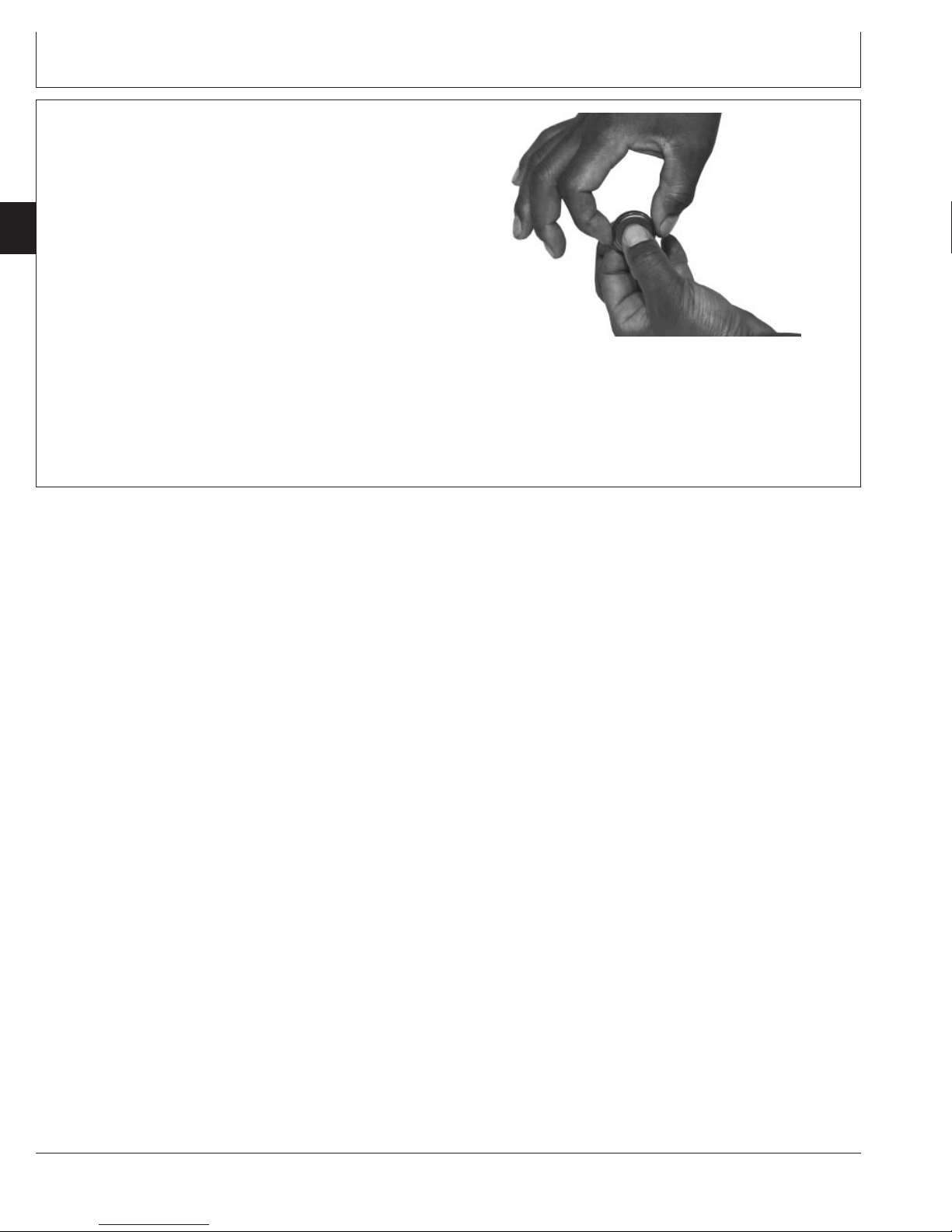
Cylinder Head and Valves
Inspect Valve Rotators
Valve rotators cannot be repaired. Replace valve rotators
when valves are replaced or reground.
02
Ensure that valve rotators turn freely in both directions.
020
Replace if defective.
26
Inspecting Valve Rotator
RG8323 –UN–21MAY98
RG,RG34710,77 –19–30SEP97–1/1
CTM100 (06APR04)
02-020-26
P
OWERTECH
10.5 L & 12.5 L Diesel Engines
040604
PN=98
 Loading...